EP3434042B1 - High penetration alerting for airborne lte - Google Patents
High penetration alerting for airborne lte Download PDFInfo
- Publication number
- EP3434042B1 EP3434042B1 EP17706347.6A EP17706347A EP3434042B1 EP 3434042 B1 EP3434042 B1 EP 3434042B1 EP 17706347 A EP17706347 A EP 17706347A EP 3434042 B1 EP3434042 B1 EP 3434042B1
- Authority
- EP
- European Patent Office
- Prior art keywords
- mobile terminal
- incoming call
- communication terminal
- communication
- alerting
- Prior art date
- Legal status (The legal status is an assumption and is not a legal conclusion. Google has not performed a legal analysis and makes no representation as to the accuracy of the status listed.)
- Not-in-force
Links
Images





Classifications
-
- H—ELECTRICITY
- H04—ELECTRIC COMMUNICATION TECHNIQUE
- H04W—WIRELESS COMMUNICATION NETWORKS
- H04W4/00—Services specially adapted for wireless communication networks; Facilities therefor
- H04W4/02—Services making use of location information
- H04W4/025—Services making use of location information using location based information parameters
-
- H—ELECTRICITY
- H04—ELECTRIC COMMUNICATION TECHNIQUE
- H04B—TRANSMISSION
- H04B7/00—Radio transmission systems, i.e. using radiation field
- H04B7/14—Relay systems
- H04B7/15—Active relay systems
- H04B7/185—Space-based or airborne stations; Stations for satellite systems
- H04B7/1853—Satellite systems for providing telephony service to a mobile station, i.e. mobile satellite service
- H04B7/18558—Arrangements for managing communications, i.e. for setting up, maintaining or releasing a call between stations
-
- H—ELECTRICITY
- H04—ELECTRIC COMMUNICATION TECHNIQUE
- H04L—TRANSMISSION OF DIGITAL INFORMATION, e.g. TELEGRAPHIC COMMUNICATION
- H04L65/00—Network arrangements, protocols or services for supporting real-time applications in data packet communication
- H04L65/60—Network streaming of media packets
- H04L65/61—Network streaming of media packets for supporting one-way streaming services, e.g. Internet radio
- H04L65/611—Network streaming of media packets for supporting one-way streaming services, e.g. Internet radio for multicast or broadcast
-
- H—ELECTRICITY
- H04—ELECTRIC COMMUNICATION TECHNIQUE
- H04W—WIRELESS COMMUNICATION NETWORKS
- H04W4/00—Services specially adapted for wireless communication networks; Facilities therefor
- H04W4/12—Messaging; Mailboxes; Announcements
- H04W4/14—Short messaging services, e.g. short message services [SMS] or unstructured supplementary service data [USSD]
-
- H—ELECTRICITY
- H04—ELECTRIC COMMUNICATION TECHNIQUE
- H04W—WIRELESS COMMUNICATION NETWORKS
- H04W52/00—Power management, e.g. Transmission Power Control [TPC] or power classes
- H04W52/04—Transmission power control [TPC]
- H04W52/30—Transmission power control [TPC] using constraints in the total amount of available transmission power
- H04W52/32—TPC of broadcast or control channels
- H04W52/325—Power control of control or pilot channels
-
- H—ELECTRICITY
- H04—ELECTRIC COMMUNICATION TECHNIQUE
- H04W—WIRELESS COMMUNICATION NETWORKS
- H04W68/00—User notification, e.g. alerting and paging, for incoming communication, change of service or the like
- H04W68/005—Transmission of information for alerting of incoming communication
-
- H—ELECTRICITY
- H04—ELECTRIC COMMUNICATION TECHNIQUE
- H04W—WIRELESS COMMUNICATION NETWORKS
- H04W72/00—Local resource management
- H04W72/20—Control channels or signalling for resource management
- H04W72/21—Control channels or signalling for resource management in the uplink direction of a wireless link, i.e. towards the network
-
- H—ELECTRICITY
- H04—ELECTRIC COMMUNICATION TECHNIQUE
- H04W—WIRELESS COMMUNICATION NETWORKS
- H04W72/00—Local resource management
- H04W72/50—Allocation or scheduling criteria for wireless resources
- H04W72/54—Allocation or scheduling criteria for wireless resources based on quality criteria
- H04W72/542—Allocation or scheduling criteria for wireless resources based on quality criteria using measured or perceived quality
-
- H—ELECTRICITY
- H04—ELECTRIC COMMUNICATION TECHNIQUE
- H04W—WIRELESS COMMUNICATION NETWORKS
- H04W84/00—Network topologies
- H04W84/02—Hierarchically pre-organised networks, e.g. paging networks, cellular networks, WLAN [Wireless Local Area Network] or WLL [Wireless Local Loop]
- H04W84/022—One-way selective calling networks, e.g. wide area paging
-
- H—ELECTRICITY
- H04—ELECTRIC COMMUNICATION TECHNIQUE
- H04W—WIRELESS COMMUNICATION NETWORKS
- H04W52/00—Power management, e.g. Transmission Power Control [TPC] or power classes
- H04W52/04—Transmission power control [TPC]
- H04W52/30—Transmission power control [TPC] using constraints in the total amount of available transmission power
- H04W52/32—TPC of broadcast or control channels
- H04W52/322—Power control of broadcast channels
-
- H—ELECTRICITY
- H04—ELECTRIC COMMUNICATION TECHNIQUE
- H04W—WIRELESS COMMUNICATION NETWORKS
- H04W52/00—Power management, e.g. Transmission Power Control [TPC] or power classes
- H04W52/04—Transmission power control [TPC]
- H04W52/30—Transmission power control [TPC] using constraints in the total amount of available transmission power
- H04W52/32—TPC of broadcast or control channels
- H04W52/327—Power control of multicast channels
-
- H—ELECTRICITY
- H04—ELECTRIC COMMUNICATION TECHNIQUE
- H04W—WIRELESS COMMUNICATION NETWORKS
- H04W76/00—Connection management
- H04W76/10—Connection setup
- H04W76/18—Management of setup rejection or failure
Definitions
- This disclosure relates to informing a mobile terminal at a degraded location of an incoming call from a communication terminal using alerting signals.
- Wireless communication networks provide communication content, such as voice, video, packet data, messaging, and broadcast.
- a wireless communication network may support operation on multiple carriers, each carrier including a range of frequencies used for communication and associated with system information describing operation of the carrier.
- a Long-Term Evolution (LTE) network provides wireless communication of high-speed data for User Equipment (UE) and communication terminals, such as ground base-stations and high altitude platforms (HAPs). LTE networks increase the capacity and speed of existing radio access network (RAN) technologies by using a different radio interface with core network improvements.
- the wireless communication network may include a number of communication terminals that can support communication for a number of UEs.
- a mobile terminal e.g., UE
- the communication signals directed toward a target mobile terminal may become degraded or lost due to large building penetration loss, or when the target mobile terminal is otherwise located at a degraded location that does not receive coverage by the HAPs.
- the degradation of communication signals can result in the mobile terminal not having the ability to receive an incoming call and not being alerted of the incoming call.
- outgoing calls where a user may simply move to a location with better signal conditions, such as near a window, the user cannot take the same corrective action to receive an incoming call, because the timing of the incoming call is unknown to the user.
- Satellite systems are known to transmit special waveforms with signal waveform qualities that allow for deeper indoor penetration to alert a mobile terminal of an incoming call.
- LTE communications include waveforms defined by the LTE standard that do not provide an option for defining a special waveform for providing a high penetration alerting channel.
- Document EP 0 844 745 A2 discloses a satellite 14 receiving transmissions and configuration commands from different earth stations 12 via a feeder link, and retransmitting each transmission in a configuration determined by the corresponding configuration command.
- the configuration commands select a beam, power level and frequency for retransmission.
- the satellite 14 can receive on the feeder link from any one of the earth stations 12 at any one time, by means of a broad beam feeder link antenna covering the whole field of view of the satellite 14 on the earth.
- Document WO 98/31165 A2 discloses a method for transmitting a message to a user terminal located in a shadow region in a telecommunications system based on a radio connection.
- the method comprises the steps of unsuccessfully paging a user terminal on a normal paging channel of the telecommunications system, and transmitting a high penetration message to said user terminal on at least one high penetration paging channel.
- the user terminal starts listening to a paging channel allocated for transmission of a high penetration paging message and, in response to reception of the high penetration paging message, indicates the reception of the message by means of indicators arranged in the user terminal.
- Document US 2004/242211 A1 discloses a callback mobile subscriber station capable of receiving a numeric page when the callback mobile subscriber station is located in an area where regular cellular telephone service is unavailable, by receiving data on a low frequency channel that is capable of service in the subscriber's present location.
- the subscriber can then initiate a callback call to the calling party when they are in an active service area by simply activating the callback function on the callback mobile subscriber station.
- the callback mobile subscriber station stores the calling party's telephone number and automatically places a call to that number when the callback feature is activated.
- the subscriber can use a land-line based telephone to return the missed incoming call, even though there is no cellular service in their present location.
- Document KR 2006 0007605 A discloses a mobile communication terminal for performing a call processing function with a base station.
- the mobile communication terminal comprise a receiving unit for receiving a paging signal, an LCD panel for displaying a call reception failure signal and a general page message and a timer for starting counting after reception.
- the mobile terminal further comprise an alarm generating unit for generating an alarm sound.
- One aspect of the disclosure provides a method for providing an alert notification to a user at a degraded location.
- the method includes obtaining, by data processing hardware of a mobile terminal, incoming call data indicating the mobile terminal is unable to establish a first communication link with a communication terminal for receiving an incoming call (e.g., using voice over long term evolution).
- the method also includes providing, by the data processing hardware, the alert notification to a user associated with the mobile terminal based on the obtained incoming call data.
- the alert notification informs the user that the incoming call directed toward the mobile terminal is pending.
- the method also includes receiving, at the data processing hardware, the incoming call from the communication terminal after the user moves the mobile terminal away from the degraded location and establishes the first communication link with the communication terminal.
- obtaining the incoming call data includes, after the communication terminal transmits a paging signal at a first power level or a first effective isotropic radiated power to the mobile terminal that requests the mobile terminal to establish the first communication link, receiving, at the data processing hardware, an alerting signal including the incoming call data from the communication terminal through a network.
- the communication terminal may use a high power spot beam to transmit the alerting signal at a second power level or a second effective isotropic radiated power greater than the first power level or the first effective isotropic radiated power of the paging signal.
- the communication terminal may increase a gain associated with the high power spot beam relative to the paging signal to enable the mobile terminal to close an uplink with the communication terminal for receiving the alerting signal or the paging signal.
- receiving the alerting signal includes receiving a text message via the high power spot beam from the communication terminal and providing the alert notification includes displaying the text message on a graphical user interface executing on the mobile terminal.
- the text message may provide at least one of: status information informing the user that the incoming call is currently pending; contact information associated with an originator of the incoming call; or location information informing the user that the mobile terminal is located in an area with poor reception.
- the alerting signal received from the communication terminal may prompt an application executing on the mobile terminal to generate the alert notification and at least one of rendering the alert notification for display upon a graphical user interface executing on the mobile terminal, or control one or more speakers of the mobile terminal to produce an audio signal associated with the alert notification.
- the method may include transmitting a connection request to the communication terminal to establish a second communication link with the communication terminal for receiving the incoming call and receiving, at the data processing hardware, the incoming call from the communication terminal through the second communication link.
- the communication terminal uses the high power spot beam to provide the incoming call through the second communication link.
- obtaining the incoming call data includes executing, by the data processing hardware, an alerting application on the mobile terminal.
- the alerting application may be configured to monitor a multicast-broadcast single-frequency network channel and receive an alerting signal directed toward the mobile terminal from the communication terminal on the multicast-broadcast single-frequency network channel.
- the alerting signal may include the incoming call data.
- the alerting application may further be configured to generate the alerting notification based on the detected alerting signal, and at least one of: render the alert notification for display upon a graphical user interface executing on the mobile terminal; or control one or more speakers of the mobile terminal to produce an audio signal associated with the alert notification.
- the communication terminal may include an antenna array providing multiple sectors.
- the communication terminal may be configured to increase a power level of the multicast-broadcast single-frequency network channel. In some examples, the communication terminal increases the power level of the multicast-broadcast single-frequency network channel by transmitting the alerting signal from each sector. In these examples, the communication terminal may combine the alerting signal from each sector using cyclic delay diversity.
- the alerting application receives the alerting signal directed toward the mobile terminal by identifying a unique identifier associated with the mobile terminal included in the alerting signal.
- the alerting application may also monitor the multicast-broadcast single-frequency network channel according to a paging cycle when the mobile terminal is located within more than one multimedia broadcast/multicast service areas.
- Obtaining the incoming call data may include executing, by the data processing hardware, an alerting application on the mobile terminal.
- the alerting application may be configured to receive modem parameters from a modem executing on the mobile terminal, determine whether the modem parameters indicate multiple unsuccessful attempts by the modem to establish the first communication link with the communication terminal, and generate the alert notification when the received modem parameters indicate multiple unsuccessful attempts by the modem to establish the first communication link.
- the alerting application may further include rendering the alert notification for display upon a graphical user interface executing on the mobile terminal, or controlling one or more speakers of the mobile terminal to produce an audio signal associated with the alert notification.
- the alerting application may determine the modem parameters indicating multiple unsuccessful attempts by the modem to establish the first communication link when the received modem parameters include multiple unsuccessful random access channel attempts by the modem.
- obtaining the incoming call data includes receiving, at the data processing hardware, an alerting signal including the incoming call data over a non-long term evolution network.
- the received signal may prompt an alerting application executing on the mobile terminal to generate the alert notification and at least one of rendering the alert notification for display upon a graphical user interface executing on the mobile terminal, or controlling one or more speakers of the mobile terminal to produce an audio signal associated with the alert notification.
- Receiving the alerting signal may include receiving a text message over the non-long term evolution network and providing the alert notification may include displaying the text message on a graphical user interface executing on the mobile terminal.
- the text message may provide at least one of: status information informing the user that the incoming call is currently pending; contact information associated with an originator of the incoming call; or location information informing the user that the mobile terminal is located in an area with poor reception.
- the system includes a communication terminal, data processing hardware of a mobile terminal, and memory hardware in communication with the data processing hardware.
- the memory hardware stores instructions that when executed on the data processing hardware cause the data processing hardware to perform operations.
- the operations include obtaining incoming call data indicating the mobile terminal is unable to establish a first communication link with the communication terminal for receiving an incoming call using voice over long term evolution and providing the alert notification to the user associated with the mobile terminal based on the obtained incoming call data.
- the alert notification informs the user that the incoming call directed toward the mobile terminal is pending.
- the operations further include receiving the incoming call from the communication terminal after the user moves the mobile terminal away from the degraded location and establishes the first communication link with the communication terminal.
- obtaining the incoming call data includes, after the communication terminal transmits a paging signal at a first power level or a first effective isotropic radiated power to the mobile terminal that requests the mobile terminal to establish the first communication link, receiving an alerting signal including the incoming call data from the communication terminal through a network.
- the communication terminal may use a high power spot beam to transmit the alerting signal at a second power level or a second effective isotropic radiated power greater than the first power level or the first effective isotropic radiated power of the paging signal.
- the communication terminal may increase a gain associated with the high power post beam relative to the paging signal to enable the mobile terminal to close an uplink with the communication terminal for receiving the alerting signal or the paging signal.
- receiving the alerting signal includes receiving a text message via the high power spot beam from the communication terminal.
- the text message may provide at least one of: status information informing the user that the incoming call is currently pending; contact information associated with an originator of the incoming call; or location information informing the user that the mobile terminal is located in an area with poor reception.
- Providing the alerting notification may include displaying the text message on a graphical user interface executing on the mobile terminal.
- the alerting signal received from the communication terminal may prompt an application executing on the mobile terminal to generate the alert notification and at least one of rendering the alert notification for display upon a graphical user interface executing on the mobile terminal, or controlling one or more speakers of the mobile terminal to produce an audio signal associated with the alert notification.
- the operations may further include transmitting a connection request to the communication terminal to establish a second communication link with the communication terminal for receiving the incoming call, and receiving the incoming call from the communication terminal through the second communication link.
- the communication terminal may use the high power spot beam to provide the incoming call through the second communication link.
- Obtaining the incoming call data may include executing an alerting application on the mobile terminal.
- the alerting application may be configured to: monitor a multicast-broadcast single-frequency network channel; receive an alerting signal directed toward the mobile terminal from the communication terminal on the multicast-broadcast single-frequency network channel; and generate the alerting notification based on the detected alerting signal.
- the alerting signal may include the incoming call data.
- the alerting application may also be configured to render the alert notification for display upon a graphical user interface executing on the mobile terminal, or control one or more speakers of the mobile terminal to produce an audio signal associated with the alert notification.
- the communication terminal includes an antenna array providing multiple sectors.
- the communication terminal may be configured to increase a power level of the multicast-broadcast single-frequency network channel.
- the communication terminal increases the power level of the multicast-broadcast single-frequency network channel by transmitting the alerting signal from each sector.
- the communication terminal may combine the alerting signal from each sector using cyclic delay diversity.
- the alerting application may receive the alerting signal directed toward the mobile terminal by identifying a unique identifier associated with the mobile terminal included in the alerting signal.
- the alerting application may monitor the multicast-broadcast single-frequency network channel according to a paging cycle when the mobile terminal is located within more than one multimedia broadcast/multicast service areas.
- obtaining the incoming call data includes executing an alerting application on the mobile terminal.
- the alerting application may be configured to: receive modem parameters from a modem executing on the mobile terminal; determine whether the modem parameters indicate multiple unsuccessful attempts by the modem to establish the first communication link with the communication terminal; and generate the alert notification when the received modem parameters indicate multiple unsuccessful attempts by the modem to establish the first communication link.
- the alerting application may also be configured to render the alert notification for display upon a graphical user interface executing on the mobile terminal, or control one or more speakers of the mobile terminal to produce an audio signal associated with the alert notification.
- the alerting application may further determine that the modem parameters indicate multiple unsuccessful attempts by the modem to establish the first communication link when the received modem parameters include multiple unsuccessful random access channel attempts by the modem.
- Obtaining the incoming call data may also include receiving an alerting signal including the incoming call data over a non-long term evolution network.
- the received alerting signal may prompt an alerting application executing on the mobile terminal to generate the alert notification and at least one of: rendering the alert notification for display upon a graphical user interface executing on the mobile terminal; or controlling one or more speakers of the mobile terminal to produce an audio signal associated with the alert notification.
- Receiving the alerting signal may include receiving a text message over the non-long term evolution network and providing the alert notification may include displaying the text message on a graphical user interface executing on the mobile terminal.
- the text message may provide at least one of: status information informing the user that the incoming call is currently pending; contact information associated with an originator of the incoming call; or location information informing the user that the mobile terminal is located in an area with poor reception.
- LTE Long-Term Evolution
- GSM/EDGE Global System for Mobile Communications/Enhanced Data Rates for GSM Evolution
- UMTS/HSPA Universal Mobile Telecommunication System/High Speed Packet Access
- LTE is configured to increase the capacity and speed of the telecommunication by using different radio interfaces in addition to core network improvements.
- LTE supports scalable carrier bandwidths, from 1.4 MHz to 20MHz and supports both frequency division duplexing (FDD) and time-division duplexing (TDD).
- FDD frequency division duplexing
- TDD time-division duplexing
- LTE networks can include terrestrial networks associated with communication terminals positioned on earth, non-terrestrial networks associated with communication terminals not positioned on earth, or a network that supports LTE and includes both terrestrial and non-terrestrial networks.
- the communication terminals associated with terrestrial networks can include high altitude platforms (HAPs) released into the earth's atmosphere that operate at high altitudes.
- HAPs high altitude platforms
- a communication terminal e.g., a HAP or base-station
- scenarios may exist when signal conditions become degraded or lost when the target UE is located indoors due to building penetration loss, or when the UE is otherwise located in a dead zone of the communication terminal.
- a user associated with the target UE may be entirely unaware of the incoming call when the LTE communications are degraded or lost. Therefore, it is desirable to design a network that supports LTE communications and is capable of alerting a UE of an incoming call to provide a user associated with the UE with an opportunity to move the UE to a location with better signal conditions to receive the incoming call.
- VoIP Voice over LTE
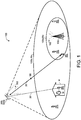
- a hybrid network 100 includes terrestrial network(s) 100a and non-terrestrial network(s) 100b.
- the terrestrial network 100a may include one or more of macrocell, femtocell, picocell, and microcell, each defining a coverage range of the network.
- the terrestrial network 100a includes multiple terrestrial base-stations 120.
- the terrestrial base-stations 120 are Evolved node Bs (also referred to as eNode B or eNB).
- An eNB is hardware that connects to the mobile terrestrial network 100a and communicates directly with one or more User Equipment (UE) 200.
- UE 200 and “mobile terminal” are used interchangeably.
- the eNB 120 does not have a separate controller element, thus simplifying the architecture of the terrestrial network 100a (i.e., the hybrid network 100).
- the eNB 120 uses two E-UTRA protocols, the Orthogonal Frequency-Division Multiple Access (OFDMA) for downlink and the Single-carrier FDMA (SC-FDMA) for uplink.
- OFDMA Orthogonal Frequency-Division Multiple Access
- SC-FDMA Single-carrier FDMA
- the eNB 120 embeds its own control functionality, since it does not include a separate controller element.
- the eNB 120 uses multiple protocols when interfacing with different elements. For example, the eNB 120 includes X2-interface using X2-AP protocol when communicating with other eNBs 120.
- the non-terrestrial network 100b may include one or more HAPs 300.
- the HAPs 300 include aerial communication devices that operate at high altitudes (e.g., 17-22 km). Each HAP 300 may be released into the earth's atmosphere, e.g., by an air craft, or flown to the desired altitude. Moreover, the HAP 300 may operate as a quasi-stationary aircraft.
- the HAP 300 is an aircraft 300a ( FIG. 3A ), such as an unmanned aerial vehicle (UAV); while in other examples, the HAP 300 is a communication balloon 300b ( FIG. 3B ).
- the HAP 300 may transmit/receive LTE-based communications 22 to/from UEs 200 located within the non-terrestrial network 100b.
- the non-terrestrial network 100b is deployed in areas where the terrestrial network 100a already exists, and therefore, the non-terrestrial network 100b must consider and coexist with existing or legacy software architecture employed by the terrestrial network 100a.
- the introduction of non-terrestrial signals 302 (e.g., LTE signals) from a HAP 300 to the network 100 may interfere with terrestrial signals 102, such as 2G/3G/4G LTE signals, from a base-station 120 of the terrestrial network 100a.
- the non-terrestrial network 100b may provide a geographical coverage region Rb that is larger than a geographical coverage region Ra provided by the terrestrial network 100a.
- Carrier aggregation or channel aggregation may be used to overcome the interference caused by the terrestrial network 100a and the non-terrestrial network 100b.
- UEs 200 located in a coverage area of multiple carriers may achieve wider bandwidth and higher data rates by using multiple carriers simultaneously.
- CA increases the bandwidth of a communication link 20 and thereby increasing the bitrate, mainly used in LTE systems.
- CA may be used for both Frequency-Division Duplexing (FDD) and Time-Division Duplexing (TDD).
- FDD refers to the transmitting device (e.g., HAP 300) and the receiving device (e.g., UE 200) operating at different carrier frequencies; while TDD refers to applying time-division multiplexing to separate transmit and receive signals using the same carrier frequency.
- a carrier signal is a transmitted electromagnetic pulse or wave at a steady base frequency of alternation on which information is imposed by increasing signal strength, varying the wave phase, or other means, i.e., modulation.
- structures such as buildings 30, create penetration loss to the LTE signals 302 from a HAP 300 to a target UE 200 located indoors within the building 30.
- the penetration loss can result in the inability for the target UE 200 to establish a communication link 20 with the HAP 300 for receiving communications 20 such as an incoming call directed toward the UE 200 using VoLTE.
- FIG. 1 shows an open communication link 20 between the HAP 300 and the UE 200 located within the building 30.
- the dashed line indicates the communication link 20 is open, and thus not established.
- the HAP 300 is able to provide LTE signals having a low data rate to the UE 200 on the downlink, but there is insufficient margin in the uplink for the UE 200 to close and establish the communication link 20 when the UE 200 is at a degraded location, e.g., within the building 30.
- a degraded location e.g., within a building 30
- a user 32 associated the UE 200 may not be informed of the incoming call due to the inability of the UE 200 to acknowledge the page from the HAP 300 for establishing the communication link 20 with the HAP 300.
- UEs 200 may be any telecommunication device capable of transmitting and/or receiving voice/data over the network 100.
- UEs 200 may include, but are not limited to, mobile computing devices, such as laptops 200a, tablets 200b, smart phones 200c, wearable computing devices 200d (e.g., headsets and/or watches), smart books, netbooks, cordless phones, wireless local loop (WLL) stations, and Bluetooth devices.
- UEs 200 may also include other computing devices having other form factors, such as computing devices included in desktop computers 200e, vehicles, gaming devices, televisions, or other appliances (e.g., networked home automation devices and home appliances).
- the UEs 200 are configured to support one or more wireless technologies, such as, but not limited to, Long Term Evolution (LTE), Wideband Code Division Multiple Access (WCDMA), CDMA IX, Evolution-Data Optimized (EVDO), Time Division Synchronous Code Division Multiple Access (TD-SCDMA), Global System for Mobile Communications (GSM), IEEE 802.11.
- LTE Long Term Evolution
- WCDMA Wideband Code Division Multiple Access
- CDMA IX Code Division Multiple Access
- EVDO Evolution-Data Optimized
- TD-SCDMA Time Division Synchronous Code Division Multiple Access
- GSM Global System for Mobile Communications
- IEEE 802.11 IEEE 802.11
- the HAP 300 is an aircraft 300a or a communication balloon 300b and includes an antenna system 310 that receives/transmits a communication 22 from a UE 200.
- the antenna system 310 is a phased array antenna system (e.g., tracking antenna) that includes a wideband active phased array antenna 312 and antenna data processing hardware 314.
- the antenna data processing hardware 314 is part of the HAP data processing hardware 320, 320a, 320b.
- the phased array antenna system 310 provides fast beam steering, which is the ability to generate simultaneous beams and dynamically adjust the characteristics of the beam patterns.
- the phased array antenna 312, 312a, 312b includes a set of individual antennas that transmit and/or receive radio waves.
- the individual antennas are connected together in such a way that the individual current of each antenna has a specific amplitude and phase relationship, allowing the individual antennas to act as a single antenna.
- the relative phases of the respective signals feeding the antennas of the phased array antenna are set in a manner that an effective radiation pattern of the array is reinforced in a desired direction and suppressed in undesired directions.
- the phase relationships between the individual antennas may be fixed (e.g., a tower array antenna), or adjustable (e.g., beam steering antenna).
- the phased array antenna 312, 312a, 312b includes antennas disposed on a micro strip and a phase shifter connected to at least one of the antennas. Moreover, the wideband active phased array antenna 312, 312a, 312b allows the transmission of the message bandwidth, which significantly exceeds the coherence bandwidth of the channel. In some examples, active phased array antennas 312, 312a, 312b incorporate transmit amplification with phase shift in each antenna element or group of elements.
- the antenna data processing hardware 314, 314a, 314b of the phased array antenna system 310 may include the tracking device 316, 316a, 316b or may be in communication with the tracking device 316, 316a, 316b.
- the data processing hardware 314, 314a, 314b of the phased array antenna system 310 is configured to identify a target coverage area (e.g., the non-terrestrial network 100b) for allowing communication 22 to be transmitted/received between the phased array antenna system 310 and UEs 200 (e.g., UEs 200 having a line-of-sight with the phased array antenna 312) and establish a communication connection or link 20 between the target HAP 300 and the UE(s) 200.
- a target coverage area e.g., the non-terrestrial network 100b
- UEs 200 e.g., UEs 200 having a line-of-sight with the phased array antenna 312
- building penetration los may obstruct the communication 22 from
- the HAP 300 includes a data processing device 320 that processes the received communication 22 and determines a path of the communication 22 to arrive at a destination UE 200.
- the data processing device 320 may include a modem 322 that processes the received communication before transmitting it to a destination (i.e., between two UEs 200).
- FIG. 3A shows an example aircraft 300a, such as an unmanned aerial vehicle (UAV).
- UAV unmanned aerial vehicle
- a UAV also known as a drone, is an aircraft without a human pilot onboard.
- UAVs There are two types of UAVs, autonomous aircrafts and remotely piloted aircraft.
- autonomous aircrafts are designed to autonomously fly, while remotely piloted aircrafts are in communication with a pilot who pilots the aircraft.
- the aircraft 300a is remotely piloted and autonomous at the same time.
- the UAV usually includes wings to maintain stability, a Global Positioning System (GPS) to guide it through its autonomous piloting, and a power source (e.g., internal combustion engine or electric battery) to maintain long hours of flight.
- GPS Global Positioning System
- a power source e.g., internal combustion engine or electric battery
- the UAV is designed to maximize efficiency and reduce drag during flight. Other UAV designs may be used as well.
- FIG. 3B shows an example communication balloon 300b that includes a balloon 330 (e.g., sized about 49 feet in width and 39 feet in height and filled with helium or hydrogen), an equipment box 332, and solar panels 334.
- the equipment box 332 includes a location data processing device 336 that executes algorithms to determine where the communication balloon 300b needs to go. Each communication balloon 300b moves into a layer of wind blowing in a direction that may take it where it should be going.
- the equipment box 332 also includes batteries to store power and a transceiver (e.g., in communication with an antenna (not shown)) to communicate with other HAPs 300.
- the solar panels 334 may power the equipment box 332.
- the equipment box 332 includes the data processing device 320, which includes the modem 322.
- Communication balloons 300b are typically released in to the earth's stratosphere to attain an altitude between 11 to 23 miles and provide connectivity for a ground area of 25 miles in diameter at speeds comparable to terrestrial wireless data services (such as, 3G or 4G).
- the communication balloons 300b float in the stratosphere, at an altitude twice as high as airplanes and the weather (e.g., 20 km above the earth's surface).
- the high-altitude balloons 300b are carried around the earth by winds and can be steered by rising or descending to an altitude with winds moving in the desired direction. Winds in the stratosphere are usually steady and move slowly at about 5 and 20 mph, and each layer of wind varies in direction and magnitude.
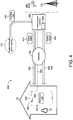
- FIG. 4 shows an example communication system 400 of a terminal 402 transmitting a paging signal 410 to an example mobile terminal (e.g., UE) 200 through the network 100 that requests the mobile terminal 200 to establish a first communication link 20a for receiving an incoming call 412 using VoLTE.
- the terminal 402 may receive the incoming call 412 from an external network 100, e.g., a packet data network (PDN) or the Internet, in communication with the terminal 402.
- PDN packet data network
- the terminal 402 is a HAP 300 operating at a high altitude within the Earth's atmosphere.
- the terminal 402 is a ground base-station 120 or eNB.
- the mobile terminal 200 may be located at a degraded location within a building 30 that prevents the mobile terminal 200 from establishing the communication link 20a for receiving the incoming call 412. In other scenarios, the mobile terminal 200 may be at a degraded location when located near an edge of a geographical coverage region Ra, Rb provided by the communication terminal 402.
- the terminal 402 transmits the paging signal 410 through the network 100 (e.g. LTE network) via a downlink channel 420.
- the paging signal 410 may be associated with a low data rate providing only enough data to request the mobile terminal 200 to establish the communication link 20a for receiving the incoming call 412.
- the downlink channel 420 providing the paging signal 410 may include a Physical Downlink Shared Channel (PDSCH) or a Physical Downlink Control Channel.
- PDSCH Physical Downlink Shared Channel
- the mobile terminal 200 successfully receives the paging signal 410 from the terminal 402 but is unable close an uplink with the communication terminal 402 to establish the communication link 20. In other examples, the mobile terminal 200 never receives the paging signal 410. Whether the mobile terminal 200 fails to receive the paging signal 410, or receives the paging signal 410 but is unable to establish the communication link 20a, a user 32 associated with the mobile terminal 200 is left unaware of the incoming call 412.
- PDSCH Physical
- the terminal 402 may employ control circuitry or data processing hardware 404 (e.g., antenna data processing hardware 314 and/or HAP data processing hardware 320) that determines whether or not the first communication link 20a is established after transmitting the paging signal 410.
- the terminal 402 may transmit an alerting signal 450 to the mobile terminal 200.
- the alerting signal 450 includes incoming call data indicating that the mobile terminal 200 is unable to establish the communication link 20a for receiving the incoming call 412.
- the mobile terminal 200 uses the incoming call data included in the alerting signal 450 to inform a user 32 associated with the mobile terminal 200 of the incoming call 412.
- the data processing hardware 404 of the terminal 402 transmits the alerting signal 450 when the communication link 20 remains open after a predetermined amount since transmitting the paging signal 410.
- the dotted line in FIG. 4 indicates the communication link 20a is open.
- the communication terminal 402 uses a high power spot beam 520 ( FIG. 5 ) to transmit the alerting signal 450 to the mobile terminal 200.
- the communication terminal 402 transmits the alerting signal 450 on a multicast-broadcast single-frequency network (MBSFN) channel 620 ( FIG. 6 ).
- MBSFN multicast-broadcast single-frequency network
- the communication terminal 402 may employ any suitable technique for transmitting the alerting signal 450 over the network 100 to ensure that the mobile terminal 200 at the degraded location successfully receives the alerting signal 450.
- the mobile terminal 200 in response to receiving the alerting signal 450 from the communication terminal 402, provides an alert notification 250 to a user 32 associated with the mobile terminal 200.
- the alert notification 250 informs the user 32 that the incoming call 412 directed toward the mobile terminal 200 is pending.
- the mobile terminal 200 provides the alert notification 250 by displaying the alert notification 250 on a graphical user interface (GUI) 202 executing on the mobile terminal 200.
- GUI graphical user interface
- the mobile terminal 200 may control one or more speakers 204 to produce an audio signal 252 associated with the alert notification 250. That is, the audio signal 252 includes a special alert notification audio signal 252 to inform the user 32 of the pending incoming call 412 with or without the user 32 having to visually view the alert notification 250 upon the GUI 202.
- the alert notification 250 may correspond to a visual alert notification for display upon the GUI 202 and/or an audio alert notification output from the speakers 204.
- the alert notification 250 can provide the user 32 with information including, but not limited to, status information 452 ( FIG. 5A ) informing the user 32 that the incoming call 412 is currently pending, contact information 454 ( FIG. 5A ) associated with an originator of the incoming call, and/or location information 456 ( FIG. 5A ) informing the user 32 that the mobile terminal 200 is located at a degraded location indicative of an area with degraded/poor reception.
- the user 32 may move the mobile terminal 200 away from the degraded location to a location providing better reception so that the first communication link 20a can be established for receiving the incoming call 412. For instance, the user 32 may move to a location near a window within the building 30 that provides better reception to establish the communication link 20a.
- schematic views 500a, 500b show the communication terminal 402 using a high power spot beam 520 to transmit the alerting signal 450 to the mobile terminal 200 through the network 100.
- the communication terminal 402 may transmit the paging signal 410 at a first power level or an Effective Isotropic Radiated Power (EIRP) to the mobile terminal 200.
- EIRP is the apparent power transmitted towards a receiver, if it is assumed that the signal is radiated equally in all directions, such as a spherical wave emanating from a point source.
- the EIRP is the arithmetic product of the power supplied to an antenna and its gain.
- the communication terminal 402 determines whether the mobile terminal 200 has established the first communication link 20a for receiving the incoming call 412. For instance, the communication terminal 402 may determine the first communication link 20a is established upon receiving a Physical Random Access Channel (PRACH) signal from the mobile terminal 200 and transmitting a Random Access Response (RAR) back to the mobile terminal 200.
- PRACH Physical Random Access Channel
- RAR Random Access Response
- the communication terminal 402 may assume that the mobile terminal 200 is located at a degraded location and transmits the alerting signal 450 using the high power spot beam 520 to inform the mobile terminal 200 of the incoming call 412 and the inability to establish the first communication link 20a while the mobile terminal 200 is at a degraded location.
- the communication terminal 402 may: (a) transmit the same signal using a high power spot beam; (b) transmit the same signal with higher power; (c) transmit the same signal using a high power spot beam and with higher power; (d) transmit an alerting signal (e.g., MBSFN, etc.); or (e) alert from another network like 2g/3g/wifi.
- the communication terminal 402 may employ a phased array antenna system 312 to increase a gain of the high power spot beam 520 relative to a gain of the paging signal 410 to transmit the high power spot beam 520 at a second power level or a second EIRP greater than the first power level associated with the paging signal 410.
- the higher gain associated with the high power spot beam 520 enables the mobile terminal 200 to close an uplink so that the communication terminal 402 can successfully transmit the alerting signal 450 through the high power spot beam 520 to the mobile terminal 200.
- the high power spot beam 520 may be associated with a narrow-low data rate exclusively used for closing the link to provide the alerting signal 450 that includes the incoming call data to inform the mobile terminal 200 of the pending incoming call 412.
- the mobile terminal 200 receives the alerting signal 450 as a text message 450a via the high power spot beam 520 from the communication terminal 402.
- the text message 450a may provide at least one of status information 452 informing the user 32 that the incoming call 412 is currently pending, contact information 454 associated with an originator of the incoming call 412; or location information 456 informing the user 32 that the mobile terminal 200 is located in a degraded area.
- the contact information 454 may include a name and/or phone number associated with the originator of the incoming call 412.
- the mobile terminal 200 In response to receiving the text message 450a, the mobile terminal 200 provides the alert notification 450 by displaying the text message 450a on the GUI 202 executing on the mobile terminal 200.
- FIG. 5A shows the GUI 202 displaying the status information 452, the contact information 454, and the location information 456 associated with the text message 450a.
- the alert notification 450 provides the user 32 with an opportunity to move the mobile terminal 200 to an area with better signal strength to establish the first communication link 20a for receiving the incoming call 412 using VoLTE.
- the mobile terminal 200 executes one or more software applications 220.
- a software application 220 may refer to computer software that, when executed by a computing device, causes the computing device to perform a task.
- the software application 220 may be referred to as an "application”, an "app”, or a "program”.
- Example software applications 220 include, but are not limited to, word processing applications, spreadsheet applications, messaging applications, media streaming applications, social networking applications, and games.
- Applications 220 can be executed on a variety of different mobile terminals (e.g., UE) 200. In some examples, applications 220 are installed on the mobile terminal 200 prior to the user 32 purchasing the mobile terminal 200. In other examples, the user 32 may download and install applications 220 on the mobile terminal 200.
- UE mobile terminals
- the mobile terminal 200 executes an alerting application 220 that wirelessly communicates with the network 100 to receive the alerting signal 450 from the communication terminal 402, e.g., via the high power spot beam 520, and generate the alert notification 250 based on the incoming call data included in the alerting signal 450.
- the alerting application 220 may cause the mobile terminal 200 to close the high power spot beam 520 via uplink signaling to permit the communication terminal 402 to transmit the alerting signal 450.
- the alerting signal 450 when received at the mobile terminal 200, prompts the alerting application 220 to generate the alert notification 250 and at least one of render the alert notification 250 for display upon the GUI 202 or control the one or more speakers 204 to produce an audio signal 252 associated with the alert notification 250. That is, the audio signal 252 includes a special alert notification audio signal 252 to inform the user 32 of the pending incoming call 412. Accordingly, the alerting application 220 may generate the alert notification 250 to provide the user 32 with an opportunity to move the mobile terminal 200 to an area with better signal strength to establish the first communication link 20a for receiving the incoming call 412 using VoLTE.
- the alerting application 220 may render a graphical button 254 on the GUI 202, that when selected by the user 32, enables the mobile terminal 200 to receive the incoming call 412 over the high power spot beam 520 from the communication terminal 402.
- the high power spot beam 520 may provide the incoming call 412 using 4GLTE, 2G, 3G, or other wireless communications such as Worldwide Interoperability for Microwave Access (WiMAX).
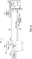
- a schematic view 600 shows the communication terminal 402 transmitting the alerting signal 450 to the mobile terminal 200 on a MBSFN channel 620.
- the communication terminal 402 may transmit the paging signal 410 to the mobile terminal 200 and determine (e.g., via the data processing hardware 404) whether the first communication link 20a for receiving the incoming call 412 has been established within the predetermined period of time since transmitting the paging signal 410.
- the communication terminal 402 may assume that the mobile terminal 200 is located in a degraded location when the first communication link 20a has not been established and transmit the alerting signal 450 to the mobile terminal 200 on the MBSFN channel 620 to inform the mobile terminal 200 of the incoming call 412.
- the MBSFN channel 620 allows the communication terminal 402 to transmit the alerting signal 450 without requiring any uplink signaling from the mobile terminal 200.
- the communication terminal 402 may increase a power level of the MBSFN channel 620 relative to other channels when transmitting the alerting signal 450 such that the alerting signal 450 includes a signal strength sufficient for successfully reaching the mobile terminal 200 at the degraded location.
- the communication terminal 402 can manage power consumption.
- the communication terminal 402 employs the phased array antenna system 312 to provide transmission coverage over multiple sectors 313a-n (e.g., antenna elements), thereby enabling the communication terminal 402 to increase the power level of the MBSFN channel 620 by transmitting the alerting signal 450 from each sector 313a-n using cyclic delay diversity (CCD).
- CCD cyclic delay diversity
- the MBSFN channel 620 may be implemented in terrestrial networks by transmitting the same alerting signal 450 from multiple terrestrial networks each separated by distance from one another.
- the communication terminals associated with the terrestrial networks can all transmit the same alerting signal 450 and use a cyclic prefix in the mobile broadband service (MBS) frames to allow for different arrival times of the alerting signal 450 at the mobile terminal 200 to be treated as multipath.
- Employing additional communication terminals may increase the coverage area and increase the signal strength of the alerting signal 450.
- Cyclic delay allows the alerting signal 450 received by the mobile terminal 200 to appear as multipath. Accordingly, cyclic delay can alleviate implications of interference when communication terminals transmitting the same signal are close to each other.
- the mobile terminal 200 executes the alerting application 220 to monitor the MBSFN channel 620 and receive the alerting signal 450 directed toward the mobile terminal 200 from the communication terminal 402 on the MBSFN channel 620.
- the alerting application 220 may obtain scheduling information for different multimedia broadcast/multicast service (MBMS) areas associated with the mobile terminal to determine a paging cycle for monitoring the MBSFN channel 620 such that the alerting application 220 does not need to monitor all MBMS subframes.
- alerting signal 450 transmitted by the communication terminal 402 includes a unique identifier 460 associated with the target mobile terminal 200.
- the alerting application 220 may receive the alerting signal 450 directed toward the mobile terminal 200 by identifying that the unique identifier 460 included in the alerting signal 450 is associated with the mobile terminal 200.
- the alerting application 220 may generate the alert notification 250 based on the incoming call data included in the received alerting signal 450 and at least one of render the alert notification 250 for display upon the GUI 202, or control the one or more speakers 204 to produce the audio signal 252 associated with the alert notification 250. Accordingly, the alerting application 220 may generate the alert notification 250 to provide the user 32 with an opportunity to move the mobile terminal 200 to an area with better signal strength to establish the first communication link 20a for receiving the incoming call 412 using VoLTE.
- FIG. 7 shows an example mobile terminal 200 obtaining the incoming call data informing the mobile terminal 200 of the incoming call 412 without receiving an alerting signal 450 from the communication terminal 402.
- the mobile terminal 200 executes an alerting application 220 in communication with a modem 260 executing on the mobile terminal 200.
- the alerting application 220 is configured to receive modem parameters 262 from the modem 260 and determine whether the modem parameters 262 indicate multiple unsuccessful attempts by the modem 260 to close the uplink for establishing the first communication link 20a with the communication terminal 402.
- modem parameters 262 indicating multiple unsuccessful attempts by them modem 260 to close the uplink provides a correlation that the incoming call 412 directed toward the mobile terminal 200 is currently pending.
- the modem parameters 262 may provide information including, but not limited to, whether or not the modem 260 has received a paging signal 410 from the communication terminal 402, a number of unsuccessful RACH attempts 264, 264a-n by the modem 260, and/or a signal strength 266 at the modem 262.
- the alerting application 220 determines multiple unsuccessful attempts by the modem 260 to close the uplink when the number of unsuccessful RACH attempts 264 after receiving the paging signal 410 exceeds a threshold.
- the alerting application 220 may determine that the modem 260 is unable to close the uplink, and thus unable to establish the first communication link 20a, when the modem 260 receives the paging signal 410 and the signal strength 266 of the modem 260 is less than a signal strength threshold.
- the alerting application 220 may require that both the signal strength 266 is less than the signal strength threshold and the number of unsuccessful RACH attempts 264 exceeds the threshold after receiving the paging signal 410 to determine the incoming call 412 is currently pending.
- the alerting application 220 determines the received modem parameters 262 indicate multiple unsuccessful attempts by the modem 260 to close the uplink for establishing the first communication link 20a
- the alerting application 220 generates the alert notification 250 based on the received modem parameters 262 and at least one of renders the alert notification 250 for display upon the GUI 202, or controls the one or more speakers 204 to produce the audio signal 252 associated with the alert notification 250. Accordingly, the alerting application 220 may generate the alert notification 250 to provide the user 32 with an opportunity to move the mobile terminal 200 to an area with better (e.g. increased) signal strength 266 to establish the first communication link 20a for receiving the incoming call 412 using VoLTE.
- a modem software application 220 associated with the modem 260 is configured to monitor the modem parameters 262 and generate the alert notification 250 when the modem parameters 262 are indicative of multiple unsuccessful attempts by the modem 262 to close the uplink for establishing the communication link 20a with the communication terminal. Moreover, the modem software application 220 may render the notification 250 upon the GUI and/or control the speakers 204 to produce the audio signal 252 associated with the notification 250.
- schematic views 800a, 800b show the mobile terminal 200 receiving the alerting signal 450 including the incoming call data from the communication terminal 402 over a non-LTE network 820, 820a-b.
- the communication terminal 402 transmits the paging signal 410 to the mobile terminal 200 through the LTE network 100 via the downlink channel 420, and when the communication terminal 402 determines the mobile terminal 200 fails to establish the communication link 20a for receiving the incoming call 412 using VoLTE, the communication terminal 402 transmits the alerting signal 450 initially over the LTE network 100.
- an access point 802 in communication with the communication terminal 402 receives the alerting signal 450 from the communication terminal 402 and provides the alerting signal 450 over a Wireless Fidelity (WiFi) (e.g., 802.11) network 820a.
- WiFi Wireless Fidelity
- the WiFi network 820a may include various types of networks, such as a local area network (LAN) or a wide area network (WAN).
- the mobile terminal 200 executes the alerting application 220 configured to generate the alert notification 250 based on the incoming call data included in the alerting signal 450 received over the WiFi network 820a and at least one of render the alert notification 250 on the GUI 202 or control the one or more speakers 204 to produce the audio signal 252 associated with the alert notification 250.
- the communication terminal 402 transmits the alerting signal 450 as a text message 450a and the mobile terminal 200 receives the text message 450a from the access point 802 via the WiFi network 820a.
- the mobile terminal 200 provides the alert notification 250 by displaying the text message 450a upon the GUI 202 as described above with reference to FIG. 5A .
- a base-station 120 in communication with the communication terminal 402 receives the alerting signal 450 from the communication terminal 402 and provides the alerting signal 450 to the mobile terminal 200 over a 2G/3G network 820b.
- the mobile terminal 200 may receive the alerting signal 450 from the base-station 120 over the 2G/3G network 820b through roaming capabilities.
- the mobile terminal 200 executes the alerting application 250 configured to generate the alert notification 250 based on the incoming call data included in the alerting signal 450 received over the 2G/3G network 820b and at least one of render the alert notification 250 on the GUI 202 or control the one or more speakers 204 to produce the audio signal 252 associated with the alert notification 250.
- the alerting application 250 configured to generate the alert notification 250 based on the incoming call data included in the alerting signal 450 received over the 2G/3G network 820b and at least one of render the alert notification 250 on the GUI 202 or control the one or more speakers 204 to produce the audio signal 252 associated with the alert notification 250.
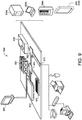
- FIG. 9 is schematic view of an example computing device 900 that may be used to implement the systems and methods described in this document.
- the computing device 900 is intended to represent various forms of digital computers, such as laptops, desktops, workstations, personal digital assistants, servers, blade servers, mainframes, and other appropriate computers.
- the components shown here, their connections and relationships, and their functions, are meant to be exemplary only, and are not meant to limit implementations of the disclosure described and/or claimed in this document.
- the computing device 900 includes a processor 910 (e.g., data processing hardware), memory 920, memory hardware or a storage device 930, a high-speed interface/controller 940 connecting to the memory 920 and high-speed expansion ports 950, and a low speed interface/controller 960 connecting to low speed bus 970 and storage device 930.
- a processor 910 e.g., data processing hardware
- memory 920 e.g., data processing hardware
- memory hardware or a storage device 930 e.g., data processing hardware
- a high-speed interface/controller 940 connecting to the memory 920 and high-speed expansion ports 950
- a low speed interface/controller 960 connecting to low speed bus 970 and storage device 930.
- Each of the components 910, 920, 930, 940, 950, and 960 are interconnected using various busses, and may be mounted on a common motherboard or in other manners as appropriate.
- the processor (e.g., data processing hardware) 910 can process instructions for execution within the computing device 900 (e.g., mobile terminal 200), including instructions stored in the memory 920 or on the storage device 930 to display graphical information for a graphical user interface (GUI) (e.g., GUI 202) on an external input/output device, such as display 980 coupled to high speed interface 940.
- GUI graphical user interface
- multiple processors and/or multiple buses may be used, as appropriate, along with multiple memories and types of memory.
- multiple computing devices 900 may be connected, with each device providing portions of the necessary operations (e.g., as a server bank, a group of blade servers, or a multi-processor system).
- the memory 920 stores information non-transitorily within the computing device 900.
- the memory 920 may be a computer-readable medium, a volatile memory unit(s), or non-volatile memory unit(s).
- the non-transitory memory 920 may be physical devices used to store programs (e.g., sequences of instructions) or data (e.g., program state information) on a temporary or permanent basis for use by the computing device 900.
- non-volatile memory examples include, but are not limited to, flash memory and read-only memory (ROM) / programmable read-only memory (PROM) / erasable programmable read-only memory (EPROM) / electronically erasable programmable read-only memory (EEPROM) (e.g., typically used for firmware, such as boot programs).
- volatile memory examples include, but are not limited to, random access memory (RAM), dynamic random access memory (DRAM), static random access memory (SRAM), phase change memory (PCM) as well as disks or tapes.
- the storage device 930 is capable of providing mass storage for the computing device 900.
- the storage device 930 is a computer-readable medium.
- the storage device 930 may be a floppy disk device, a hard disk device, an optical disk device, or a tape device, a flash memory or other similar solid state memory device, or an array of devices, including devices in a storage area network or other configurations.
- a computer program product is tangibly embodied in an information carrier.
- the computer program product contains instructions that, when executed, perform one or more methods, such as those described above.
- the information carrier is a computer- or machine-readable medium, such as the memory 920, the storage device 930, or memory on processor 910.
- the high speed controller 940 manages bandwidth-intensive operations for the computing device 900, while the low speed controller 960 manages lower bandwidth-intensive operations. Such allocation of duties is exemplary only.
- the high-speed controller 940 is coupled to the memory 920, the display 980 (e.g., through a graphics processor or accelerator), and to the high-speed expansion ports 950, which may accept various expansion cards (not shown).
- the low-speed controller 960 is coupled to the storage device 930 and low-speed expansion port 970.
- the low-speed expansion port 970 which may include various communication ports (e.g., USB, Bluetooth, Ethernet, wireless Ethernet), may be coupled to one or more input/output devices, such as a keyboard, a pointing device, a scanner, or a networking device, such as a switch or router, e.g., through a network adapter.
- input/output devices such as a keyboard, a pointing device, a scanner, or a networking device, such as a switch or router, e.g., through a network adapter.
- the computing device 900 may be implemented in a number of different forms, as shown in the figure. For example, it may be implemented as a standard server 900a or multiple times in a group of such servers 900a, as a laptop computer 900b, as part of a rack server system 900c, or as a mobile terminal 200, 200b.
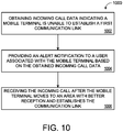
- FIG. 10 is a flowchart of an example method 1000 for providing an alert notification 250 to a user 32 associated with a mobile terminal 200 that informs the user 32 that an incoming call 412 directed toward the mobile terminal 200 is pending.
- the mobile terminal 200 may be located in a degraded location.
- the flowchart starts at operation 1002 where data processing hardware 910 of the mobile terminal 200 obtains incoming call data indicating that the mobile terminal 200 is unable to establish a first communication link 20a with a communication terminal 402 for receiving an incoming call 412 using VoLTE.
- the data processing hardware 910 may obtain the incoming call data by receiving an alerting signal 450 that includes the incoming call data from the communication terminal 402.
- the communication terminal 402 may transmit the alerting signal 450 through a high power spot beam 520 ( FIGS. 5A and 5B ) or a MBSFN channel 620 ( FIG. 6 ).
- the data processing hardware 910 receives the alerting signal 450 over a WiFi network 820a from an access point 802 in communication with the communication terminal 402; while in the example of FIG. 8B , the data processing hardware 910 receives the alerting signal 450 over a 2G/3G network 820b from a base-station 120 in communication with the communication terminal 402.
- the data processing hardware 910 obtains the incoming call data by receiving modem parameters 262 from a modem 260 executing on the mobile terminal ( FIG. 7 ).
- the modem parameters 262 may include an indication that a paging signal 410 has been received at the modem 260, a number of unsuccessful RACH attempts 264 by the modem, and/or a signal strength 266 of the modem 260.
- the data processing hardware 910 at the mobile terminal 200 provides the alert notification 250 to the user 32 associated with the mobile terminal 200 based on the obtained incoming call data.
- the alerting signal 450 includes a text message 450a containing the incoming call data
- the mobile terminal 200 provides the alert notification 250 by displaying the text message 450a on a GUI 202 executing on the mobile terminal 200.
- the data processing hardware 910 executes a software application 220 (e.g., alerting application) configured to generate the alert notification 250 based on the obtained incoming call data and at least one of render the notification 250 on the GUI 202, or control one or more speakers 204 of the mobile terminal 200 to produce an audio signal 252 associated with the alert notification 250.
- a software application 220 e.g., alerting application
- the data processing hardware 910 receives the incoming call 412 using VoLTE from the communication terminal 402 after the mobile terminal 200 moves from the degraded location to an area with better reception for establishing the first communication link 20a with the communication terminal 402.
- obtaining the incoming call data includes, after the communication terminal 402 transmits a paging signal 410 at a first power level or a first effective isotropic radiated power to the mobile terminal 200 that requests the mobile terminal 200 to establish the first communication link 20a, receiving, at the data processing hardware 910, an alerting signal 450 including the incoming call data from the communication terminal 402 through a network 100.
- the communication terminal 402 uses a high power spot beam 520 to transmit the alerting signal 450 at a second power level or a second effective isotropic radiated power greater than the first power level or the first effective isotropic radiated power of the paging signal 410.
- the communication terminal 402 increases a gain associated with the high power spot beam 520 relative to the paging signal 410 to enable the mobile terminal 200 to close an uplink 20 with the communication terminal 402 for receiving the alerting signal 450.
- receiving the alerting signal 450 includes receiving a text message 450a via the high power spot beam 520 from the communication terminal 402.
- the text message 450a optionally provides at least one of: (i) status information 452 informing the user 32 that the incoming call 412 is currently pending; (ii) contact information 454 associated with an originator of the incoming call 412; or (iii) location information 456 informing the user 32 that the mobile terminal 200 is located in an area with poor reception.
- Providing the alert notification 250 may include displaying the text message 450a on a graphical user interface 202 executing on the mobile terminal 200.
- the alerting signal 450 received from the communication terminal 402 may prompt an application 220 executing on the mobile terminal 200 to generate the alert notification 250 and at least one of: (i) render the alert notification 250 for display 980 upon a graphical user interface 202 executing on the mobile terminal 200; or (ii) control one or more speakers 204 of the mobile terminal 200 to produce an audio signal 252 associated with the alert notification 250.
- the method 1000 includes, in response to receiving the alerting signal 450 from the communication terminal 402, transmitting a connection request to the communication terminal 402 to establish a second communication link 20b with the communication terminal 402 for receiving the incoming call 412.
- the method 1000 may further include receiving, at the data processing hardware 910, the incoming call 412 from the communication terminal 402 through the second communication link 20b.
- the communication terminal 402 may use the high power spot beam 520 to provide the incoming call 412 through the second communication link 20b.
- obtaining the incoming call data includes executing, by the data processing hardware 910, an alerting application 220 on the mobile terminal 200.
- the alerting application 220 may be configured to: (i) monitor a multicast-broadcast single-frequency network channel; (ii) receive an alerting signal 450 directed toward the mobile terminal 200 from the communication terminal 402 on the multicast-broadcast single-frequency network channel, where the alerting signal 450 includes the incoming call data; (iii) generate the alerting notification 250 based on the detected alerting signal 450; and (iv) at least one of: (a) render the alert notification 250 for display (980) upon a graphical user interface 202 executing on the mobile terminal 200; or (b) control one or more speakers 204 of the mobile terminal 200 to produce an audio signal 252 associated with the alert notification 250.
- the communication terminal 402 may include an antenna array 312 providing multiple sectors 313a-n.
- the communication terminal 402 may be configured to at least one of increase a power level of the multicast-broadcast single-frequency network channel, increase the power level of the multicast-broadcast single-frequency network channel by transmitting the alerting signal 450 from each sector 313, or increase the power level of the multicast-broadcast single-frequency network channel by transmitting the alerting signal 450 from each sector 313 and combining the alerting signal 450 from each sector 313 using cyclic delay diversity.
- the alerting application 220 may optionally receive the alerting signal 450 directed toward the mobile terminal 200 by identifying a unique identifier 460 associated with the mobile terminal 200 included in the alerting signal 450. In some examples, the alerting application 220 monitors the multicast-broadcast single-frequency network channel according to a paging cycle when the mobile terminal 200 is located within more than one multimedia broadcast/multicast service areas.
- Obtaining the incoming call data may, in some examples, include executing, by the data processing hardware 910, an alerting application 220 on the mobile terminal 200.
- the alerting application 220 may be configured to: (i) receive modem parameters 262 from a modem 260 executing on the mobile terminal 200; (ii) determine whether the modem parameters 262 indicate multiple unsuccessful attempts by the modem 260 to establish the first communication link 20a with the communication terminal 402; (iii) generate the alert notification 250 when the received modem parameters 262 indicate multiple unsuccessful attempts by the modem 260 to establish the first communication link 20a; and (iv) at least one of: (a) render the alert notification 250 for display 980 upon a graphical user interface 202 executing on the mobile terminal 200; or (b) control one or more speakers 204 of the mobile terminal 200 to produce an audio signal 252 associated with the alert notification 250.
- the altering application 220 may determine that the modem parameters 262 indicate multiple unsuccessful attempts by the modem 260 to establish the first communication link 20a when the received modem parameters 262 include multiple unsuccessful random access channel attempts by the modem 260. Moreover, obtaining the incoming call data may include receiving, at the data processing hardware 910, an alerting signal 450 including the incoming call data over a non-long term evolution network 820, 820a, 820b.
- the received alerting signal 450 prompts the alerting application 220 executing on the mobile terminal 200 to generate the alert notification 250 and at least one of: (a) render the alert notification 250 for display 980 upon a graphical user interface 202 executing on the mobile terminal 200; or (b) control one or more speakers 204 of the mobile terminal 200 to produce an audio signal 252 associated with the alert notification 250.
- receiving the alerting signal 450 includes receiving a text message 450a over the non-long term evolution network 820, 820a, 820b.
- the text message 450a may provide at least one of: (i) status information 452 informing the user 32 that the incoming call 412 is currently pending; (ii) contact information 454 associated with an originator of the incoming call 412; or (iii) location information 456 informing the user 32 that the mobile terminal 200 is located in an area with poor reception.
- Providing the alert notification 250 may include displaying the text message 450a on a graphical user interface 202 executing on the mobile terminal 200.
- implementations of the systems and techniques described here can be realized in digital electronic and/or optical circuitry, integrated circuitry, specially designed ASICs (application specific integrated circuits), computer hardware, firmware, software, and/or combinations thereof.
- ASICs application specific integrated circuits
- These various implementations can include implementation in one or more computer programs that are executable and/or interpretable on a programmable system including at least one programmable processor, which may be special or general purpose, coupled to receive data and instructions from, and to transmit data and instructions to, a storage system, at least one input device, and at least one output device.
- Implementations of the subject matter and the functional operations described in this specification can be implemented in digital electronic circuitry, or in computer software, firmware, or hardware, including the structures disclosed in this specification and their structural equivalents, or in combinations of one or more of them.
- subject matter described in this specification can be implemented as one or more computer program products, i.e., one or more modules of computer program instructions encoded on a computer readable medium for execution by, or to control the operation of, data processing apparatus.
- the computer readable medium can be a machine-readable storage device, a machine-readable storage substrate, a memory device, a composition of matter effecting a machine-readable propagated signal, or a combination of one or more of them.
- data processing apparatus encompass all apparatus, devices, and machines for processing data, including by way of example a programmable processor, a computer, or multiple processors or computers.
- the apparatus can include, in addition to hardware, code that creates an execution environment for the computer program in question, e.g., code that constitutes processor firmware, a protocol stack, a database management system, an operating system, or a combination of one or more of them.
- a propagated signal is an artificially generated signal, e.g., a machine-generated electrical, optical, or electromagnetic signal that is generated to encode information for transmission to suitable receiver apparatus.
- a computer program (also known as an application, program, software, software application, script, or code) can be written in any form of programming language, including compiled or interpreted languages, and it can be deployed in any form, including as a stand-alone program or as a module, component, subroutine, or other unit suitable for use in a computing environment.
- a computer program does not necessarily correspond to a file in a file system.
- a program can be stored in a portion of a file that holds other programs or data (e.g., one or more scripts stored in a markup language document), in a single file dedicated to the program in question, or in multiple coordinated files (e.g., files that store one or more modules, sub programs, or portions of code).
- a computer program can be deployed to be executed on one computer or on multiple computers that are located at one site or distributed across multiple sites and interconnected by a communication network.
- the processes and logic flows described in this specification can be performed by one or more programmable processors executing one or more computer programs to perform functions by operating on input data and generating output.
- the processes and logic flows can also be performed by, and apparatus can also be implemented as, special purpose logic circuitry, e.g., an FPGA (field programmable gate array) or an ASIC (application specific integrated circuit).
- processors suitable for the execution of a computer program include, by way of example, both general and special purpose microprocessors, and any one or more processors of any kind of digital computer.
- a processor will receive instructions and data from a read only memory or a random access memory or both.
- the essential elements of a computer are a processor for performing instructions and one or more memory devices for storing instructions and data.
- a computer will also include, or be operatively coupled to receive data from or transfer data to, or both, one or more mass storage devices for storing data, e.g., magnetic, magneto optical disks, or optical disks.
- mass storage devices for storing data, e.g., magnetic, magneto optical disks, or optical disks.
- a computer need not have such devices.
- a computer can be embedded in another device, e.g., a mobile telephone, a personal digital assistant (PDA), a mobile audio player, a Global Positioning System (GPS) receiver, to name just a few.
- Computer readable media suitable for storing computer program instructions and data include all forms of non-volatile memory, media and memory devices, including by way of example semiconductor memory devices, e.g., EPROM, EEPROM, and flash memory devices; magnetic disks, e.g., internal hard disks or removable disks; magneto optical disks; and CD ROM and DVD-ROM disks.
- the processor and the memory can be supplemented by, or incorporated in, special purpose logic circuitry.
- one or more aspects of the disclosure can be implemented on a computer having a display device, e.g., a CRT (cathode ray tube), LCD (liquid crystal display) monitor, or touch screen for displaying information to the user and optionally a keyboard and a pointing device, e.g., a mouse or a trackball, by which the user can provide input to the computer.
- a display device e.g., a CRT (cathode ray tube), LCD (liquid crystal display) monitor, or touch screen for displaying information to the user and optionally a keyboard and a pointing device, e.g., a mouse or a trackball, by which the user can provide input to the computer.
- Other kinds of devices can be used to provide interaction with a user as well; for example, feedback provided to the user can be any form of sensory feedback, e.g., visual feedback, auditory feedback, or tactile feedback; and input from the user can be received in any form, including acoustic, speech, or tactile input
- One or more aspects of the disclosure can be implemented in a computing system that includes a backend component, e.g., as a data server, or that includes a middleware component, e.g., an application server, or that includes a frontend component, e.g., a client computer having a graphical user interface or a Web browser through which a user can interact with an implementation of the subject matter described in this specification, or any combination of one or more such backend, middleware, or frontend components.
- the components of the system can be interconnected by any form or medium of digital data communication, e.g., a communication network.
- Examples of communication networks include a local area network (“LAN”) and a wide area network (“WAN”), an inter-network (e.g., the Internet), and peer-to-peer networks (e.g., ad hoc peer-to-peer networks).
- LAN local area network
- WAN wide area network
- inter-network e.g., the Internet
- peer-to-peer networks e.g., ad hoc peer-to-peer networks.
- the computing system can include clients and servers.
- a client and server are generally remote from each other and typically interact through a communication network. The relationship of client and server arises by virtue of computer programs running on the respective computers and having a client-server relationship to each other.
- a server transmits data (e.g., an HTML page) to a client device (e.g., for purposes of displaying data to and receiving user input from a user interacting with the client device).
- client device e.g., for purposes of displaying data to and receiving user input from a user interacting with the client device.
- Data generated at the client device e.g., a result of the user interaction
Landscapes
- Engineering & Computer Science (AREA)
- Computer Networks & Wireless Communication (AREA)
- Signal Processing (AREA)
- Multimedia (AREA)
- Physics & Mathematics (AREA)
- Astronomy & Astrophysics (AREA)
- Aviation & Aerospace Engineering (AREA)
- General Physics & Mathematics (AREA)
- Quality & Reliability (AREA)
- Mobile Radio Communication Systems (AREA)
- Telephone Function (AREA)
Description
- This disclosure relates to informing a mobile terminal at a degraded location of an incoming call from a communication terminal using alerting signals.
- Wireless communication networks provide communication content, such as voice, video, packet data, messaging, and broadcast. A wireless communication network may support operation on multiple carriers, each carrier including a range of frequencies used for communication and associated with system information describing operation of the carrier. A Long-Term Evolution (LTE) network provides wireless communication of high-speed data for User Equipment (UE) and communication terminals, such as ground base-stations and high altitude platforms (HAPs). LTE networks increase the capacity and speed of existing radio access network (RAN) technologies by using a different radio interface with core network improvements. The wireless communication network may include a number of communication terminals that can support communication for a number of UEs. A mobile terminal (e.g., UE) may communicate with a communication terminal via downlink and optionally an uplink.
- When HAPs employ communications, the communication signals directed toward a target mobile terminal may become degraded or lost due to large building penetration loss, or when the target mobile terminal is otherwise located at a degraded location that does not receive coverage by the HAPs. The degradation of communication signals can result in the mobile terminal not having the ability to receive an incoming call and not being alerted of the incoming call. By contrast to outgoing calls, where a user may simply move to a location with better signal conditions, such as near a window, the user cannot take the same corrective action to receive an incoming call, because the timing of the incoming call is unknown to the user. Satellite systems are known to transmit special waveforms with signal waveform qualities that allow for deeper indoor penetration to alert a mobile terminal of an incoming call. However, LTE communications include waveforms defined by the LTE standard that do not provide an option for defining a special waveform for providing a high penetration alerting channel.
- Document
EP 0 844 745 A2 discloses a satellite 14 receiving transmissions and configuration commands from different earth stations 12 via a feeder link, and retransmitting each transmission in a configuration determined by the corresponding configuration command. The configuration commands select a beam, power level and frequency for retransmission. The satellite 14 can receive on the feeder link from any one of the earth stations 12 at any one time, by means of a broad beam feeder link antenna covering the whole field of view of the satellite 14 on the earth. - Document
WO 98/31165 A2 - Document
US 2004/242211 A1 discloses a callback mobile subscriber station capable of receiving a numeric page when the callback mobile subscriber station is located in an area where regular cellular telephone service is unavailable, by receiving data on a low frequency channel that is capable of service in the subscriber's present location. The subscriber can then initiate a callback call to the calling party when they are in an active service area by simply activating the callback function on the callback mobile subscriber station. The callback mobile subscriber station stores the calling party's telephone number and automatically places a call to that number when the callback feature is activated. Alternatively, the subscriber can use a land-line based telephone to return the missed incoming call, even though there is no cellular service in their present location. - Document
KR 2006 0007605 A - The present invention is defined in the independent claims.
- One aspect of the disclosure provides a method for providing an alert notification to a user at a degraded location. The method includes obtaining, by data processing hardware of a mobile terminal, incoming call data indicating the mobile terminal is unable to establish a first communication link with a communication terminal for receiving an incoming call (e.g., using voice over long term evolution). The method also includes providing, by the data processing hardware, the alert notification to a user associated with the mobile terminal based on the obtained incoming call data. The alert notification informs the user that the incoming call directed toward the mobile terminal is pending. The method also includes receiving, at the data processing hardware, the incoming call from the communication terminal after the user moves the mobile terminal away from the degraded location and establishes the first communication link with the communication terminal.
- Implementations of the disclosure may include one or more of the following optional features. In some implementations, obtaining the incoming call data includes, after the communication terminal transmits a paging signal at a first power level or a first effective isotropic radiated power to the mobile terminal that requests the mobile terminal to establish the first communication link, receiving, at the data processing hardware, an alerting signal including the incoming call data from the communication terminal through a network. The communication terminal may use a high power spot beam to transmit the alerting signal at a second power level or a second effective isotropic radiated power greater than the first power level or the first effective isotropic radiated power of the paging signal. The communication terminal may increase a gain associated with the high power spot beam relative to the paging signal to enable the mobile terminal to close an uplink with the communication terminal for receiving the alerting signal or the paging signal.
- In some examples, receiving the alerting signal includes receiving a text message via the high power spot beam from the communication terminal and providing the alert notification includes displaying the text message on a graphical user interface executing on the mobile terminal. The text message may provide at least one of: status information informing the user that the incoming call is currently pending; contact information associated with an originator of the incoming call; or location information informing the user that the mobile terminal is located in an area with poor reception. The alerting signal received from the communication terminal may prompt an application executing on the mobile terminal to generate the alert notification and at least one of rendering the alert notification for display upon a graphical user interface executing on the mobile terminal, or control one or more speakers of the mobile terminal to produce an audio signal associated with the alert notification.
- In response to receiving the alerting signal from the communication terminal, the method may include transmitting a connection request to the communication terminal to establish a second communication link with the communication terminal for receiving the incoming call and receiving, at the data processing hardware, the incoming call from the communication terminal through the second communication link. The communication terminal uses the high power spot beam to provide the incoming call through the second communication link.
- In some examples, obtaining the incoming call data includes executing, by the data processing hardware, an alerting application on the mobile terminal. The alerting application may be configured to monitor a multicast-broadcast single-frequency network channel and receive an alerting signal directed toward the mobile terminal from the communication terminal on the multicast-broadcast single-frequency network channel. The alerting signal may include the incoming call data. The alerting application may further be configured to generate the alerting notification based on the detected alerting signal, and at least one of: render the alert notification for display upon a graphical user interface executing on the mobile terminal; or control one or more speakers of the mobile terminal to produce an audio signal associated with the alert notification. The communication terminal may include an antenna array providing multiple sectors. The communication terminal may be configured to increase a power level of the multicast-broadcast single-frequency network channel. In some examples, the communication terminal increases the power level of the multicast-broadcast single-frequency network channel by transmitting the alerting signal from each sector. In these examples, the communication terminal may combine the alerting signal from each sector using cyclic delay diversity.
- In some implementations, the alerting application receives the alerting signal directed toward the mobile terminal by identifying a unique identifier associated with the mobile terminal included in the alerting signal. The alerting application may also monitor the multicast-broadcast single-frequency network channel according to a paging cycle when the mobile terminal is located within more than one multimedia broadcast/multicast service areas. Obtaining the incoming call data may include executing, by the data processing hardware, an alerting application on the mobile terminal. The alerting application may be configured to receive modem parameters from a modem executing on the mobile terminal, determine whether the modem parameters indicate multiple unsuccessful attempts by the modem to establish the first communication link with the communication terminal, and generate the alert notification when the received modem parameters indicate multiple unsuccessful attempts by the modem to establish the first communication link. The alerting application may further include rendering the alert notification for display upon a graphical user interface executing on the mobile terminal, or controlling one or more speakers of the mobile terminal to produce an audio signal associated with the alert notification. The alerting application may determine the modem parameters indicating multiple unsuccessful attempts by the modem to establish the first communication link when the received modem parameters include multiple unsuccessful random access channel attempts by the modem.
- In some examples, obtaining the incoming call data includes receiving, at the data processing hardware, an alerting signal including the incoming call data over a non-long term evolution network. The received signal may prompt an alerting application executing on the mobile terminal to generate the alert notification and at least one of rendering the alert notification for display upon a graphical user interface executing on the mobile terminal, or controlling one or more speakers of the mobile terminal to produce an audio signal associated with the alert notification. Receiving the alerting signal may include receiving a text message over the non-long term evolution network and providing the alert notification may include displaying the text message on a graphical user interface executing on the mobile terminal. The text message may provide at least one of: status information informing the user that the incoming call is currently pending; contact information associated with an originator of the incoming call; or location information informing the user that the mobile terminal is located in an area with poor reception.
- Another aspect of the disclosure provides a system for providing an alert notification to a user at a degraded location. The system includes a communication terminal, data processing hardware of a mobile terminal, and memory hardware in communication with the data processing hardware. The memory hardware stores instructions that when executed on the data processing hardware cause the data processing hardware to perform operations. The operations include obtaining incoming call data indicating the mobile terminal is unable to establish a first communication link with the communication terminal for receiving an incoming call using voice over long term evolution and providing the alert notification to the user associated with the mobile terminal based on the obtained incoming call data. The alert notification informs the user that the incoming call directed toward the mobile terminal is pending. The operations further include receiving the incoming call from the communication terminal after the user moves the mobile terminal away from the degraded location and establishes the first communication link with the communication terminal.
- This aspect may include one or more of the following optional features. In some implementations, obtaining the incoming call data includes, after the communication terminal transmits a paging signal at a first power level or a first effective isotropic radiated power to the mobile terminal that requests the mobile terminal to establish the first communication link, receiving an alerting signal including the incoming call data from the communication terminal through a network. The communication terminal may use a high power spot beam to transmit the alerting signal at a second power level or a second effective isotropic radiated power greater than the first power level or the first effective isotropic radiated power of the paging signal. The communication terminal may increase a gain associated with the high power post beam relative to the paging signal to enable the mobile terminal to close an uplink with the communication terminal for receiving the alerting signal or the paging signal.
- In some examples, receiving the alerting signal includes receiving a text message via the high power spot beam from the communication terminal. The text message may provide at least one of: status information informing the user that the incoming call is currently pending; contact information associated with an originator of the incoming call; or location information informing the user that the mobile terminal is located in an area with poor reception. Providing the alerting notification may include displaying the text message on a graphical user interface executing on the mobile terminal. The alerting signal received from the communication terminal may prompt an application executing on the mobile terminal to generate the alert notification and at least one of rendering the alert notification for display upon a graphical user interface executing on the mobile terminal, or controlling one or more speakers of the mobile terminal to produce an audio signal associated with the alert notification.
- In response to receiving the alerting signal from the communication terminal, the operations may further include transmitting a connection request to the communication terminal to establish a second communication link with the communication terminal for receiving the incoming call, and receiving the incoming call from the communication terminal through the second communication link. The communication terminal may use the high power spot beam to provide the incoming call through the second communication link. Obtaining the incoming call data may include executing an alerting application on the mobile terminal. The alerting application may be configured to: monitor a multicast-broadcast single-frequency network channel; receive an alerting signal directed toward the mobile terminal from the communication terminal on the multicast-broadcast single-frequency network channel; and generate the alerting notification based on the detected alerting signal. The alerting signal may include the incoming call data. The alerting application may also be configured to render the alert notification for display upon a graphical user interface executing on the mobile terminal, or control one or more speakers of the mobile terminal to produce an audio signal associated with the alert notification.
- In some implementations, the communication terminal includes an antenna array providing multiple sectors. The communication terminal may be configured to increase a power level of the multicast-broadcast single-frequency network channel. In some examples, the communication terminal increases the power level of the multicast-broadcast single-frequency network channel by transmitting the alerting signal from each sector. In these examples, the communication terminal may combine the alerting signal from each sector using cyclic delay diversity. The alerting application may receive the alerting signal directed toward the mobile terminal by identifying a unique identifier associated with the mobile terminal included in the alerting signal. The alerting application may monitor the multicast-broadcast single-frequency network channel according to a paging cycle when the mobile terminal is located within more than one multimedia broadcast/multicast service areas.
- In some examples, obtaining the incoming call data includes executing an alerting application on the mobile terminal. The alerting application may be configured to: receive modem parameters from a modem executing on the mobile terminal; determine whether the modem parameters indicate multiple unsuccessful attempts by the modem to establish the first communication link with the communication terminal; and generate the alert notification when the received modem parameters indicate multiple unsuccessful attempts by the modem to establish the first communication link. The alerting application may also be configured to render the alert notification for display upon a graphical user interface executing on the mobile terminal, or control one or more speakers of the mobile terminal to produce an audio signal associated with the alert notification. The alerting application may further determine that the modem parameters indicate multiple unsuccessful attempts by the modem to establish the first communication link when the received modem parameters include multiple unsuccessful random access channel attempts by the modem. Obtaining the incoming call data may also include receiving an alerting signal including the incoming call data over a non-long term evolution network.
- The received alerting signal may prompt an alerting application executing on the mobile terminal to generate the alert notification and at least one of: rendering the alert notification for display upon a graphical user interface executing on the mobile terminal; or controlling one or more speakers of the mobile terminal to produce an audio signal associated with the alert notification. Receiving the alerting signal may include receiving a text message over the non-long term evolution network and providing the alert notification may include displaying the text message on a graphical user interface executing on the mobile terminal. The text message may provide at least one of: status information informing the user that the incoming call is currently pending; contact information associated with an originator of the incoming call; or location information informing the user that the mobile terminal is located in an area with poor reception.
- The details of one or more implementations of the disclosure are set forth in the accompanying drawings and the description below. Other aspects, features, and advantages will be apparent from the description and drawings, and from the claims.
-
-
FIG. 1 is a schematic view of an exemplary communication system. -
FIG. 2 is a perspective view of example user equipment. -
FIGS. 3A and 3B are perspective views of example high altitude platforms. -
FIG. 4 is a schematic view of an example communication system of a communication terminal transmitting an alerting signal to a mobile terminal that informs the mobile terminal of an incoming call. -
FIGS. 5A and 5B are schematic views of a communication terminal using a high power spot beam to transmit an alerting signal to a mobile terminal. -
FIG. 6 is a schematic view of a communication terminal transmitting an alerting signal to a mobile terminal on a multicast-broadcast single-frequency network (MBSFN) channel. -
FIG. 7 is a schematic view of an example mobile terminal using modem parameters to obtain incoming call data. -
FIGS. 8A and 8B are schematic views of a mobile terminal receiving an alerting signal from a communication terminal over a non-Long-Term Evolution (LTE) network. -
FIG. 9 is a schematic view of an example computing device. -
FIG. 10 is a flowchart of an example method for providing an alert notification to a user associated with a mobile terminal at a degraded location when an incoming call is pending. - Like reference symbols in the various drawings indicate like elements.
- Long-Term Evolution (LTE) is a standard for wireless communication of high-speed data for mobile phones and data terminals. LTE is based on the Global System for Mobile Communications/Enhanced Data Rates for GSM Evolution (GSM/EDGE) and Universal Mobile Telecommunication System/High Speed Packet Access (UMTS/HSPA) network technologies. LTE is configured to increase the capacity and speed of the telecommunication by using different radio interfaces in addition to core network improvements. LTE supports scalable carrier bandwidths, from 1.4 MHz to 20MHz and supports both frequency division duplexing (FDD) and time-division duplexing (TDD). LTE networks can include terrestrial networks associated with communication terminals positioned on earth, non-terrestrial networks associated with communication terminals not positioned on earth, or a network that supports LTE and includes both terrestrial and non-terrestrial networks. The communication terminals associated with terrestrial networks can include high altitude platforms (HAPs) released into the earth's atmosphere that operate at high altitudes. When a communication terminal (e.g., a HAP or base-station) deploys LTE communications to a target UE, scenarios may exist when signal conditions become degraded or lost when the target UE is located indoors due to building penetration loss, or when the UE is otherwise located in a dead zone of the communication terminal. In addition to preventing the target UE from the ability to receive an incoming call using Voice over LTE (VoLTE), a user associated with the target UE may be entirely unaware of the incoming call when the LTE communications are degraded or lost. Therefore, it is desirable to design a network that supports LTE communications and is capable of alerting a UE of an incoming call to provide a user associated with the UE with an opportunity to move the UE to a location with better signal conditions to receive the incoming call.
- Referring to
FIG. 1 , in some implementations, ahybrid network 100 includes terrestrial network(s) 100a and non-terrestrial network(s) 100b. Theterrestrial network 100a may include one or more of macrocell, femtocell, picocell, and microcell, each defining a coverage range of the network. Theterrestrial network 100a includes multiple terrestrial base-stations 120. In some examples, the terrestrial base-stations 120 are Evolved node Bs (also referred to as eNode B or eNB). An eNB is hardware that connects to the mobileterrestrial network 100a and communicates directly with one or more User Equipment (UE) 200. As used herein, theterms UE 200 and "mobile terminal" are used interchangeably. TheeNB 120 does not have a separate controller element, thus simplifying the architecture of theterrestrial network 100a (i.e., the hybrid network 100). TheeNB 120 uses two E-UTRA protocols, the Orthogonal Frequency-Division Multiple Access (OFDMA) for downlink and the Single-carrier FDMA (SC-FDMA) for uplink. In addition, theeNB 120 embeds its own control functionality, since it does not include a separate controller element. TheeNB 120 uses multiple protocols when interfacing with different elements. For example, theeNB 120 includes X2-interface using X2-AP protocol when communicating withother eNBs 120. - In some implementations, the
non-terrestrial network 100b may include one or more HAPs 300. TheHAPs 300 include aerial communication devices that operate at high altitudes (e.g., 17-22 km). EachHAP 300 may be released into the earth's atmosphere, e.g., by an air craft, or flown to the desired altitude. Moreover, theHAP 300 may operate as a quasi-stationary aircraft. In some examples, theHAP 300 is anaircraft 300a (FIG. 3A ), such as an unmanned aerial vehicle (UAV); while in other examples, theHAP 300 is a communication balloon 300b (FIG. 3B ). TheHAP 300 may transmit/receive LTE-basedcommunications 22 to/fromUEs 200 located within thenon-terrestrial network 100b. - In some implementations, the
non-terrestrial network 100b is deployed in areas where theterrestrial network 100a already exists, and therefore, thenon-terrestrial network 100b must consider and coexist with existing or legacy software architecture employed by theterrestrial network 100a. Thus, the introduction of non-terrestrial signals 302 (e.g., LTE signals) from aHAP 300 to thenetwork 100 may interfere withterrestrial signals 102, such as 2G/3G/4G LTE signals, from a base-station 120 of theterrestrial network 100a. Thenon-terrestrial network 100b may provide a geographical coverage region Rb that is larger than a geographical coverage region Ra provided by theterrestrial network 100a. - Carrier aggregation or channel aggregation (CA) may be used to overcome the interference caused by the
terrestrial network 100a and thenon-terrestrial network 100b.UEs 200 located in a coverage area of multiple carriers may achieve wider bandwidth and higher data rates by using multiple carriers simultaneously. CA increases the bandwidth of acommunication link 20 and thereby increasing the bitrate, mainly used in LTE systems. CA may be used for both Frequency-Division Duplexing (FDD) and Time-Division Duplexing (TDD). FDD refers to the transmitting device (e.g., HAP 300) and the receiving device (e.g., UE 200) operating at different carrier frequencies; while TDD refers to applying time-division multiplexing to separate transmit and receive signals using the same carrier frequency. A carrier signal is a transmitted electromagnetic pulse or wave at a steady base frequency of alternation on which information is imposed by increasing signal strength, varying the wave phase, or other means, i.e., modulation. - In some implementations, structures, such as
buildings 30, create penetration loss to the LTE signals 302 from aHAP 300 to atarget UE 200 located indoors within thebuilding 30. The penetration loss can result in the inability for thetarget UE 200 to establish acommunication link 20 with theHAP 300 for receivingcommunications 20 such as an incoming call directed toward theUE 200 using VoLTE. For instance,FIG. 1 shows anopen communication link 20 between theHAP 300 and theUE 200 located within thebuilding 30. The dashed line indicates thecommunication link 20 is open, and thus not established. In some instances, theHAP 300 is able to provide LTE signals having a low data rate to theUE 200 on the downlink, but there is insufficient margin in the uplink for theUE 200 to close and establish thecommunication link 20 when theUE 200 is at a degraded location, e.g., within thebuilding 30. Thus, even if theHAP 300 is able to successfully page theUE 200 in a degraded location (e.g., within a building 30) to establish thecommunication link 20 for receiving acommunication 22, such as an incoming call, auser 32 associated theUE 200 may not be informed of the incoming call due to the inability of theUE 200 to acknowledge the page from theHAP 300 for establishing thecommunication link 20 with theHAP 300. - Referring to
FIG. 2 ,UEs 200 may be any telecommunication device capable of transmitting and/or receiving voice/data over thenetwork 100.UEs 200 may include, but are not limited to, mobile computing devices, such aslaptops 200a,tablets 200b,smart phones 200c,wearable computing devices 200d (e.g., headsets and/or watches), smart books, netbooks, cordless phones, wireless local loop (WLL) stations, and Bluetooth devices.UEs 200 may also include other computing devices having other form factors, such as computing devices included indesktop computers 200e, vehicles, gaming devices, televisions, or other appliances (e.g., networked home automation devices and home appliances). TheUEs 200 are configured to support one or more wireless technologies, such as, but not limited to, Long Term Evolution (LTE), Wideband Code Division Multiple Access (WCDMA), CDMA IX, Evolution-Data Optimized (EVDO), Time Division Synchronous Code Division Multiple Access (TD-SCDMA), Global System for Mobile Communications (GSM), IEEE 802.11. - Referring to
FIGS. 3A and 3B , in some implementations, theHAP 300 is anaircraft 300a or a communication balloon 300b and includes an antenna system 310 that receives/transmits acommunication 22 from aUE 200. In some examples, the antenna system 310 is a phased array antenna system (e.g., tracking antenna) that includes a wideband active phasedarray antenna 312 and antenna data processing hardware 314. In some examples, the antenna data processing hardware 314 is part of the HAPdata processing hardware 320, 320a, 320b. The phased array antenna system 310 provides fast beam steering, which is the ability to generate simultaneous beams and dynamically adjust the characteristics of the beam patterns. The phasedarray antenna array antenna array antenna array antennas - The antenna data processing hardware 314, 314a, 314b of the phased array antenna system 310 may include the tracking device 316, 316a, 316b or may be in communication with the tracking device 316, 316a, 316b. The data processing hardware 314, 314a, 314b of the phased array antenna system 310 is configured to identify a target coverage area (e.g., the
non-terrestrial network 100b) for allowingcommunication 22 to be transmitted/received between the phased array antenna system 310 and UEs 200 (e.g.,UEs 200 having a line-of-sight with the phased array antenna 312) and establish a communication connection or link 20 between thetarget HAP 300 and the UE(s) 200. However, building penetration los may obstruct thecommunication 22 from reaching aUE 200 located within a building or other structure, or may prevent theUE 200 from the ability to establish thecommunication link 20 with thetarget HAP 300. - In some examples, the
HAP 300 includes adata processing device 320 that processes the receivedcommunication 22 and determines a path of thecommunication 22 to arrive at adestination UE 200. Thedata processing device 320 may include amodem 322 that processes the received communication before transmitting it to a destination (i.e., between two UEs 200). -
FIG. 3A shows anexample aircraft 300a, such as an unmanned aerial vehicle (UAV). A UAV, also known as a drone, is an aircraft without a human pilot onboard. There are two types of UAVs, autonomous aircrafts and remotely piloted aircraft. As the name suggests, autonomous aircrafts are designed to autonomously fly, while remotely piloted aircrafts are in communication with a pilot who pilots the aircraft. In some examples, theaircraft 300a is remotely piloted and autonomous at the same time. The UAV usually includes wings to maintain stability, a Global Positioning System (GPS) to guide it through its autonomous piloting, and a power source (e.g., internal combustion engine or electric battery) to maintain long hours of flight. In some examples, the UAV is designed to maximize efficiency and reduce drag during flight. Other UAV designs may be used as well. -
FIG. 3B shows an example communication balloon 300b that includes a balloon 330 (e.g., sized about 49 feet in width and 39 feet in height and filled with helium or hydrogen), anequipment box 332, andsolar panels 334. Theequipment box 332 includes a locationdata processing device 336 that executes algorithms to determine where the communication balloon 300b needs to go. Each communication balloon 300b moves into a layer of wind blowing in a direction that may take it where it should be going. Theequipment box 332 also includes batteries to store power and a transceiver (e.g., in communication with an antenna (not shown)) to communicate withother HAPs 300. Thesolar panels 334 may power theequipment box 332. In some examples, theequipment box 332 includes thedata processing device 320, which includes themodem 322. - Communication balloons 300b are typically released in to the earth's stratosphere to attain an altitude between 11 to 23 miles and provide connectivity for a ground area of 25 miles in diameter at speeds comparable to terrestrial wireless data services (such as, 3G or 4G). The communication balloons 300b float in the stratosphere, at an altitude twice as high as airplanes and the weather (e.g., 20 km above the earth's surface). The high-altitude balloons 300b are carried around the earth by winds and can be steered by rising or descending to an altitude with winds moving in the desired direction. Winds in the stratosphere are usually steady and move slowly at about 5 and 20 mph, and each layer of wind varies in direction and magnitude.
-
FIG. 4 shows anexample communication system 400 of a terminal 402 transmitting apaging signal 410 to an example mobile terminal (e.g., UE) 200 through thenetwork 100 that requests themobile terminal 200 to establish afirst communication link 20a for receiving anincoming call 412 using VoLTE. The terminal 402 may receive theincoming call 412 from anexternal network 100, e.g., a packet data network (PDN) or the Internet, in communication with the terminal 402. In some implementations, the terminal 402 is aHAP 300 operating at a high altitude within the Earth's atmosphere. In other implementations, the terminal 402 is a ground base-station 120 or eNB. Themobile terminal 200 may be located at a degraded location within abuilding 30 that prevents the mobile terminal 200 from establishing thecommunication link 20a for receiving theincoming call 412. In other scenarios, themobile terminal 200 may be at a degraded location when located near an edge of a geographical coverage region Ra, Rb provided by thecommunication terminal 402. - The terminal 402 transmits the
paging signal 410 through the network 100 (e.g. LTE network) via adownlink channel 420. Thepaging signal 410 may be associated with a low data rate providing only enough data to request themobile terminal 200 to establish thecommunication link 20a for receiving theincoming call 412. Thedownlink channel 420 providing thepaging signal 410 may include a Physical Downlink Shared Channel (PDSCH) or a Physical Downlink Control Channel. In some examples, themobile terminal 200 successfully receives thepaging signal 410 from the terminal 402 but is unable close an uplink with thecommunication terminal 402 to establish thecommunication link 20. In other examples, themobile terminal 200 never receives thepaging signal 410. Whether themobile terminal 200 fails to receive thepaging signal 410, or receives thepaging signal 410 but is unable to establish thecommunication link 20a, auser 32 associated with themobile terminal 200 is left unaware of theincoming call 412. - The terminal 402 may employ control circuitry or data processing hardware 404 (e.g., antenna data processing hardware 314 and/or HAP data processing hardware 320) that determines whether or not the
first communication link 20a is established after transmitting thepaging signal 410. When thecommunication link 20a has not been established and is open, the terminal 402 may transmit analerting signal 450 to themobile terminal 200. The alertingsignal 450 includes incoming call data indicating that themobile terminal 200 is unable to establish thecommunication link 20a for receiving theincoming call 412. To put another way, themobile terminal 200 uses the incoming call data included in the alertingsignal 450 to inform auser 32 associated with themobile terminal 200 of theincoming call 412. In some examples, thedata processing hardware 404 of the terminal 402 transmits the alertingsignal 450 when thecommunication link 20 remains open after a predetermined amount since transmitting thepaging signal 410. The dotted line inFIG. 4 indicates thecommunication link 20a is open. In some implementations, thecommunication terminal 402 uses a high power spot beam 520 (FIG. 5 ) to transmit the alertingsignal 450 to themobile terminal 200. In other implementations, thecommunication terminal 402 transmits the alertingsignal 450 on a multicast-broadcast single-frequency network (MBSFN) channel 620 (FIG. 6 ). Thecommunication terminal 402 may employ any suitable technique for transmitting the alertingsignal 450 over thenetwork 100 to ensure that themobile terminal 200 at the degraded location successfully receives the alertingsignal 450. - In some implementations, in response to receiving the alerting
signal 450 from thecommunication terminal 402, themobile terminal 200 provides analert notification 250 to auser 32 associated with themobile terminal 200. Thealert notification 250 informs theuser 32 that theincoming call 412 directed toward themobile terminal 200 is pending. In some examples, themobile terminal 200 provides thealert notification 250 by displaying thealert notification 250 on a graphical user interface (GUI) 202 executing on themobile terminal 200. Additionally or alternatively, themobile terminal 200 may control one ormore speakers 204 to produce anaudio signal 252 associated with thealert notification 250. That is, theaudio signal 252 includes a special alert notificationaudio signal 252 to inform theuser 32 of the pendingincoming call 412 with or without theuser 32 having to visually view thealert notification 250 upon theGUI 202. Thus, thealert notification 250 may correspond to a visual alert notification for display upon theGUI 202 and/or an audio alert notification output from thespeakers 204. Thealert notification 250 can provide theuser 32 with information including, but not limited to, status information 452 (FIG. 5A ) informing theuser 32 that theincoming call 412 is currently pending, contact information 454 (FIG. 5A ) associated with an originator of the incoming call, and/or location information 456 (FIG. 5A ) informing theuser 32 that themobile terminal 200 is located at a degraded location indicative of an area with degraded/poor reception. Accordingly, theuser 32 may move themobile terminal 200 away from the degraded location to a location providing better reception so that thefirst communication link 20a can be established for receiving theincoming call 412. For instance, theuser 32 may move to a location near a window within thebuilding 30 that provides better reception to establish thecommunication link 20a. - Referring to
FIGS. 5A and 5B ,schematic views communication terminal 402 using a highpower spot beam 520 to transmit the alertingsignal 450 to themobile terminal 200 through thenetwork 100. Thecommunication terminal 402 may transmit thepaging signal 410 at a first power level or an Effective Isotropic Radiated Power (EIRP) to themobile terminal 200. The EIRP is the apparent power transmitted towards a receiver, if it is assumed that the signal is radiated equally in all directions, such as a spherical wave emanating from a point source. In other words, the EIRP is the arithmetic product of the power supplied to an antenna and its gain. Thecommunication terminal 402 determines whether themobile terminal 200 has established thefirst communication link 20a for receiving theincoming call 412. For instance, thecommunication terminal 402 may determine thefirst communication link 20a is established upon receiving a Physical Random Access Channel (PRACH) signal from themobile terminal 200 and transmitting a Random Access Response (RAR) back to themobile terminal 200. When thecommunication terminal 402 determines that thecommunication link 20a has not been established after a predetermined period of time has elapsed since transmitting thepaging signal 410, thecommunication terminal 402 may assume that themobile terminal 200 is located at a degraded location and transmits the alertingsignal 450 using the highpower spot beam 520 to inform themobile terminal 200 of theincoming call 412 and the inability to establish thefirst communication link 20a while themobile terminal 200 is at a degraded location. After some time, if acommunication link 20a has not been established thecommunication terminal 402 may: (a) transmit the same signal using a high power spot beam; (b) transmit the same signal with higher power; (c) transmit the same signal using a high power spot beam and with higher power; (d) transmit an alerting signal (e.g., MBSFN, etc.); or (e) alert from another network like 2g/3g/wifi. Thecommunication terminal 402 may employ a phasedarray antenna system 312 to increase a gain of the highpower spot beam 520 relative to a gain of thepaging signal 410 to transmit the highpower spot beam 520 at a second power level or a second EIRP greater than the first power level associated with thepaging signal 410. In doing so, the higher gain associated with the highpower spot beam 520 enables themobile terminal 200 to close an uplink so that thecommunication terminal 402 can successfully transmit the alertingsignal 450 through the highpower spot beam 520 to themobile terminal 200. The highpower spot beam 520 may be associated with a narrow-low data rate exclusively used for closing the link to provide thealerting signal 450 that includes the incoming call data to inform themobile terminal 200 of the pendingincoming call 412. - Referring to
FIG. 5A , in some implementations, themobile terminal 200 receives the alertingsignal 450 as atext message 450a via the highpower spot beam 520 from thecommunication terminal 402. Thetext message 450a may provide at least one ofstatus information 452 informing theuser 32 that theincoming call 412 is currently pending,contact information 454 associated with an originator of theincoming call 412; or location information 456 informing theuser 32 that themobile terminal 200 is located in a degraded area. Thecontact information 454 may include a name and/or phone number associated with the originator of theincoming call 412. In response to receiving thetext message 450a, themobile terminal 200 provides thealert notification 450 by displaying thetext message 450a on theGUI 202 executing on themobile terminal 200.FIG. 5A shows theGUI 202 displaying thestatus information 452, thecontact information 454, and the location information 456 associated with thetext message 450a. Accordingly, thealert notification 450 provides theuser 32 with an opportunity to move themobile terminal 200 to an area with better signal strength to establish thefirst communication link 20a for receiving theincoming call 412 using VoLTE. - Referring to
FIG. 5B , in some implementations, themobile terminal 200 executes one ormore software applications 220. Asoftware application 220 may refer to computer software that, when executed by a computing device, causes the computing device to perform a task. In some examples, thesoftware application 220 may be referred to as an "application", an "app", or a "program".Example software applications 220 include, but are not limited to, word processing applications, spreadsheet applications, messaging applications, media streaming applications, social networking applications, and games. -
Applications 220 can be executed on a variety of different mobile terminals (e.g., UE) 200. In some examples,applications 220 are installed on themobile terminal 200 prior to theuser 32 purchasing themobile terminal 200. In other examples, theuser 32 may download and installapplications 220 on themobile terminal 200. - In some implementations, the
mobile terminal 200 executes an alertingapplication 220 that wirelessly communicates with thenetwork 100 to receive the alertingsignal 450 from thecommunication terminal 402, e.g., via the highpower spot beam 520, and generate thealert notification 250 based on the incoming call data included in the alertingsignal 450. The alertingapplication 220 may cause themobile terminal 200 to close the highpower spot beam 520 via uplink signaling to permit thecommunication terminal 402 to transmit the alertingsignal 450. In some examples, the alertingsignal 450, when received at themobile terminal 200, prompts the alertingapplication 220 to generate thealert notification 250 and at least one of render thealert notification 250 for display upon theGUI 202 or control the one ormore speakers 204 to produce anaudio signal 252 associated with thealert notification 250. That is, theaudio signal 252 includes a special alert notificationaudio signal 252 to inform theuser 32 of the pendingincoming call 412. Accordingly, the alertingapplication 220 may generate thealert notification 250 to provide theuser 32 with an opportunity to move themobile terminal 200 to an area with better signal strength to establish thefirst communication link 20a for receiving theincoming call 412 using VoLTE. Optionally, the alertingapplication 220 may render agraphical button 254 on theGUI 202, that when selected by theuser 32, enables themobile terminal 200 to receive theincoming call 412 over the highpower spot beam 520 from thecommunication terminal 402. Here, the highpower spot beam 520 may provide theincoming call 412 using 4GLTE, 2G, 3G, or other wireless communications such as Worldwide Interoperability for Microwave Access (WiMAX). - Referring to
FIG. 6 , aschematic view 600 shows thecommunication terminal 402 transmitting the alertingsignal 450 to themobile terminal 200 on aMBSFN channel 620. Thecommunication terminal 402 may transmit thepaging signal 410 to themobile terminal 200 and determine (e.g., via the data processing hardware 404) whether thefirst communication link 20a for receiving theincoming call 412 has been established within the predetermined period of time since transmitting thepaging signal 410. Thecommunication terminal 402 may assume that themobile terminal 200 is located in a degraded location when thefirst communication link 20a has not been established and transmit the alertingsignal 450 to themobile terminal 200 on theMBSFN channel 620 to inform themobile terminal 200 of theincoming call 412. Conversely to using the highpower spot beam 520 ofFIGS. 5A and 5B , which requires themobile terminal 200 to close the uplink before thecommunication terminal 402 can transmit the alertingsignal 450, theMBSFN channel 620 allows thecommunication terminal 402 to transmit the alertingsignal 450 without requiring any uplink signaling from themobile terminal 200. - The
communication terminal 402 may increase a power level of theMBSFN channel 620 relative to other channels when transmitting the alertingsignal 450 such that the alertingsignal 450 includes a signal strength sufficient for successfully reaching themobile terminal 200 at the degraded location. By only increasing the power of theMBSFN channel 620, thecommunication terminal 402 can manage power consumption. In some implementations, thecommunication terminal 402 employs the phasedarray antenna system 312 to provide transmission coverage overmultiple sectors 313a-n (e.g., antenna elements), thereby enabling thecommunication terminal 402 to increase the power level of theMBSFN channel 620 by transmitting the alertingsignal 450 from eachsector 313a-n using cyclic delay diversity (CCD). - Additionally, the
MBSFN channel 620 may be implemented in terrestrial networks by transmitting thesame alerting signal 450 from multiple terrestrial networks each separated by distance from one another. In these scenarios, the communication terminals associated with the terrestrial networks can all transmit thesame alerting signal 450 and use a cyclic prefix in the mobile broadband service (MBS) frames to allow for different arrival times of the alertingsignal 450 at themobile terminal 200 to be treated as multipath. Employing additional communication terminals may increase the coverage area and increase the signal strength of the alertingsignal 450. In some examples, when communication terminals get closer together, a time difference between the terminals no longer appears as a multipath, but instead the signals appear to beamform and cause constructive and destructive interference. Cyclic delay allows the alertingsignal 450 received by themobile terminal 200 to appear as multipath. Accordingly, cyclic delay can alleviate implications of interference when communication terminals transmitting the same signal are close to each other. - In some implementations, the
mobile terminal 200 executes the alertingapplication 220 to monitor theMBSFN channel 620 and receive the alertingsignal 450 directed toward the mobile terminal 200 from thecommunication terminal 402 on theMBSFN channel 620. The alertingapplication 220 may obtain scheduling information for different multimedia broadcast/multicast service (MBMS) areas associated with the mobile terminal to determine a paging cycle for monitoring theMBSFN channel 620 such that the alertingapplication 220 does not need to monitor all MBMS subframes. In some examples, alertingsignal 450 transmitted by thecommunication terminal 402 includes aunique identifier 460 associated with the targetmobile terminal 200. While monitoring theMBSFN channel 620, the alertingapplication 220 may receive the alertingsignal 450 directed toward themobile terminal 200 by identifying that theunique identifier 460 included in the alertingsignal 450 is associated with themobile terminal 200. In response to receiving the alertingsignal 450, the alertingapplication 220 may generate thealert notification 250 based on the incoming call data included in the received alertingsignal 450 and at least one of render thealert notification 250 for display upon theGUI 202, or control the one ormore speakers 204 to produce theaudio signal 252 associated with thealert notification 250. Accordingly, the alertingapplication 220 may generate thealert notification 250 to provide theuser 32 with an opportunity to move themobile terminal 200 to an area with better signal strength to establish thefirst communication link 20a for receiving theincoming call 412 using VoLTE. -
FIG. 7 shows an examplemobile terminal 200 obtaining the incoming call data informing themobile terminal 200 of theincoming call 412 without receiving an alertingsignal 450 from thecommunication terminal 402. In some implementations, themobile terminal 200 executes an alertingapplication 220 in communication with amodem 260 executing on themobile terminal 200. The alertingapplication 220 is configured to receivemodem parameters 262 from themodem 260 and determine whether themodem parameters 262 indicate multiple unsuccessful attempts by themodem 260 to close the uplink for establishing thefirst communication link 20a with thecommunication terminal 402. Thus,modem parameters 262 indicating multiple unsuccessful attempts by themmodem 260 to close the uplink provides a correlation that theincoming call 412 directed toward themobile terminal 200 is currently pending. Themodem parameters 262 may provide information including, but not limited to, whether or not themodem 260 has received apaging signal 410 from thecommunication terminal 402, a number of unsuccessful RACH attempts 264, 264a-n by themodem 260, and/or asignal strength 266 at themodem 262. In some examples, the alertingapplication 220 determines multiple unsuccessful attempts by themodem 260 to close the uplink when the number of unsuccessful RACH attempts 264 after receiving thepaging signal 410 exceeds a threshold. In other examples, the alertingapplication 220 may determine that themodem 260 is unable to close the uplink, and thus unable to establish thefirst communication link 20a, when themodem 260 receives thepaging signal 410 and thesignal strength 266 of themodem 260 is less than a signal strength threshold. Optionally, the alertingapplication 220 may require that both thesignal strength 266 is less than the signal strength threshold and the number of unsuccessful RACH attempts 264 exceeds the threshold after receiving thepaging signal 410 to determine theincoming call 412 is currently pending. - When the alerting
application 220 determines the receivedmodem parameters 262 indicate multiple unsuccessful attempts by themodem 260 to close the uplink for establishing thefirst communication link 20a, the alertingapplication 220 generates thealert notification 250 based on the receivedmodem parameters 262 and at least one of renders thealert notification 250 for display upon theGUI 202, or controls the one ormore speakers 204 to produce theaudio signal 252 associated with thealert notification 250. Accordingly, the alertingapplication 220 may generate thealert notification 250 to provide theuser 32 with an opportunity to move themobile terminal 200 to an area with better (e.g. increased)signal strength 266 to establish thefirst communication link 20a for receiving theincoming call 412 using VoLTE. - In some implementations, a
modem software application 220 associated with themodem 260 is configured to monitor themodem parameters 262 and generate thealert notification 250 when themodem parameters 262 are indicative of multiple unsuccessful attempts by themodem 262 to close the uplink for establishing thecommunication link 20a with the communication terminal. Moreover, themodem software application 220 may render thenotification 250 upon the GUI and/or control thespeakers 204 to produce theaudio signal 252 associated with thenotification 250. - Referring to
FIGS. 8A and 8B ,schematic views mobile terminal 200 receiving the alertingsignal 450 including the incoming call data from thecommunication terminal 402 over a non-LTE network 820, 820a-b. Thecommunication terminal 402 transmits thepaging signal 410 to themobile terminal 200 through theLTE network 100 via thedownlink channel 420, and when thecommunication terminal 402 determines themobile terminal 200 fails to establish thecommunication link 20a for receiving theincoming call 412 using VoLTE, thecommunication terminal 402 transmits the alertingsignal 450 initially over theLTE network 100. - Referring to
FIG. 8A , in some implementations, anaccess point 802 in communication with thecommunication terminal 402 receives the alertingsignal 450 from thecommunication terminal 402 and provides the alertingsignal 450 over a Wireless Fidelity (WiFi) (e.g., 802.11) network 820a. The WiFi network 820a may include various types of networks, such as a local area network (LAN) or a wide area network (WAN). In some examples, themobile terminal 200 executes the alertingapplication 220 configured to generate thealert notification 250 based on the incoming call data included in the alertingsignal 450 received over the WiFi network 820a and at least one of render thealert notification 250 on theGUI 202 or control the one ormore speakers 204 to produce theaudio signal 252 associated with thealert notification 250. In other examples, thecommunication terminal 402 transmits the alertingsignal 450 as atext message 450a and themobile terminal 200 receives thetext message 450a from theaccess point 802 via the WiFi network 820a. In these examples, themobile terminal 200 provides thealert notification 250 by displaying thetext message 450a upon theGUI 202 as described above with reference toFIG. 5A . - Referring to
FIG. 8B , in some implementations, a base-station 120 (e.g., eNB) in communication with thecommunication terminal 402 receives the alertingsignal 450 from thecommunication terminal 402 and provides the alertingsignal 450 to themobile terminal 200 over a 2G/3G network 820b. Themobile terminal 200 may receive the alertingsignal 450 from the base-station 120 over the 2G/3G network 820b through roaming capabilities. In some examples, themobile terminal 200 executes the alertingapplication 250 configured to generate thealert notification 250 based on the incoming call data included in the alertingsignal 450 received over the 2G/3G network 820b and at least one of render thealert notification 250 on theGUI 202 or control the one ormore speakers 204 to produce theaudio signal 252 associated with thealert notification 250. In response to receiving the alertingsignal 450 from thecommunication terminal 402, transmitting a connection request to thecommunication terminal 402 to establish a second communication link 20b with thecommunication terminal 402 for receiving theincoming call 412. -
FIG. 9 is schematic view of anexample computing device 900 that may be used to implement the systems and methods described in this document. Thecomputing device 900 is intended to represent various forms of digital computers, such as laptops, desktops, workstations, personal digital assistants, servers, blade servers, mainframes, and other appropriate computers. The components shown here, their connections and relationships, and their functions, are meant to be exemplary only, and are not meant to limit implementations of the disclosure described and/or claimed in this document. - The
computing device 900 includes a processor 910 (e.g., data processing hardware),memory 920, memory hardware or astorage device 930, a high-speed interface/controller 940 connecting to thememory 920 and high-speed expansion ports 950, and a low speed interface/controller 960 connecting tolow speed bus 970 andstorage device 930. Each of thecomponents memory 920 or on thestorage device 930 to display graphical information for a graphical user interface (GUI) (e.g., GUI 202) on an external input/output device, such asdisplay 980 coupled tohigh speed interface 940. In other implementations, multiple processors and/or multiple buses may be used, as appropriate, along with multiple memories and types of memory. Also,multiple computing devices 900 may be connected, with each device providing portions of the necessary operations (e.g., as a server bank, a group of blade servers, or a multi-processor system). - The
memory 920 stores information non-transitorily within thecomputing device 900. Thememory 920 may be a computer-readable medium, a volatile memory unit(s), or non-volatile memory unit(s). Thenon-transitory memory 920 may be physical devices used to store programs (e.g., sequences of instructions) or data (e.g., program state information) on a temporary or permanent basis for use by thecomputing device 900. Examples of non-volatile memory include, but are not limited to, flash memory and read-only memory (ROM) / programmable read-only memory (PROM) / erasable programmable read-only memory (EPROM) / electronically erasable programmable read-only memory (EEPROM) (e.g., typically used for firmware, such as boot programs). Examples of volatile memory include, but are not limited to, random access memory (RAM), dynamic random access memory (DRAM), static random access memory (SRAM), phase change memory (PCM) as well as disks or tapes. - The
storage device 930 is capable of providing mass storage for thecomputing device 900. In some implementations, thestorage device 930 is a computer-readable medium. In various different implementations, thestorage device 930 may be a floppy disk device, a hard disk device, an optical disk device, or a tape device, a flash memory or other similar solid state memory device, or an array of devices, including devices in a storage area network or other configurations. In additional implementations, a computer program product is tangibly embodied in an information carrier. The computer program product contains instructions that, when executed, perform one or more methods, such as those described above. The information carrier is a computer- or machine-readable medium, such as thememory 920, thestorage device 930, or memory onprocessor 910. - The
high speed controller 940 manages bandwidth-intensive operations for thecomputing device 900, while thelow speed controller 960 manages lower bandwidth-intensive operations. Such allocation of duties is exemplary only. In some implementations, the high-speed controller 940 is coupled to thememory 920, the display 980 (e.g., through a graphics processor or accelerator), and to the high-speed expansion ports 950, which may accept various expansion cards (not shown). In some implementations, the low-speed controller 960 is coupled to thestorage device 930 and low-speed expansion port 970. The low-speed expansion port 970, which may include various communication ports (e.g., USB, Bluetooth, Ethernet, wireless Ethernet), may be coupled to one or more input/output devices, such as a keyboard, a pointing device, a scanner, or a networking device, such as a switch or router, e.g., through a network adapter. - The
computing device 900 may be implemented in a number of different forms, as shown in the figure. For example, it may be implemented as a standard server 900a or multiple times in a group of such servers 900a, as a laptop computer 900b, as part of a rack server system 900c, or as amobile terminal -
FIG. 10 is a flowchart of anexample method 1000 for providing analert notification 250 to auser 32 associated with amobile terminal 200 that informs theuser 32 that anincoming call 412 directed toward themobile terminal 200 is pending. Themobile terminal 200 may be located in a degraded location. The flowchart starts atoperation 1002 wheredata processing hardware 910 of themobile terminal 200 obtains incoming call data indicating that themobile terminal 200 is unable to establish afirst communication link 20a with acommunication terminal 402 for receiving anincoming call 412 using VoLTE. Thedata processing hardware 910 may obtain the incoming call data by receiving an alertingsignal 450 that includes the incoming call data from thecommunication terminal 402. Thecommunication terminal 402 may transmit the alertingsignal 450 through a high power spot beam 520 (FIGS. 5A and 5B ) or a MBSFN channel 620 (FIG. 6 ). In the example ofFIG. 8A , thedata processing hardware 910 receives the alertingsignal 450 over a WiFi network 820a from anaccess point 802 in communication with thecommunication terminal 402; while in the example ofFIG. 8B , thedata processing hardware 910 receives the alertingsignal 450 over a 2G/3G network 820b from a base-station 120 in communication with thecommunication terminal 402. In some implementations, thedata processing hardware 910 obtains the incoming call data by receivingmodem parameters 262 from amodem 260 executing on the mobile terminal (FIG. 7 ). Themodem parameters 262 may include an indication that apaging signal 410 has been received at themodem 260, a number of unsuccessful RACH attempts 264 by the modem, and/or asignal strength 266 of themodem 260. - At
operation 1004, thedata processing hardware 910 at themobile terminal 200 provides thealert notification 250 to theuser 32 associated with themobile terminal 200 based on the obtained incoming call data. In examples when the alertingsignal 450 includes atext message 450a containing the incoming call data, themobile terminal 200 provides thealert notification 250 by displaying thetext message 450a on aGUI 202 executing on themobile terminal 200. In some examples, thedata processing hardware 910 executes a software application 220 (e.g., alerting application) configured to generate thealert notification 250 based on the obtained incoming call data and at least one of render thenotification 250 on theGUI 202, or control one ormore speakers 204 of themobile terminal 200 to produce anaudio signal 252 associated with thealert notification 250. - At
operation 1006, thedata processing hardware 910 receives theincoming call 412 using VoLTE from thecommunication terminal 402 after themobile terminal 200 moves from the degraded location to an area with better reception for establishing thefirst communication link 20a with thecommunication terminal 402. - In some implementations, obtaining the incoming call data includes, after the
communication terminal 402 transmits apaging signal 410 at a first power level or a first effective isotropic radiated power to themobile terminal 200 that requests themobile terminal 200 to establish thefirst communication link 20a, receiving, at thedata processing hardware 910, an alertingsignal 450 including the incoming call data from thecommunication terminal 402 through anetwork 100. Thecommunication terminal 402 uses a highpower spot beam 520 to transmit the alertingsignal 450 at a second power level or a second effective isotropic radiated power greater than the first power level or the first effective isotropic radiated power of thepaging signal 410. In some examples, thecommunication terminal 402 increases a gain associated with the highpower spot beam 520 relative to thepaging signal 410 to enable themobile terminal 200 to close anuplink 20 with thecommunication terminal 402 for receiving the alertingsignal 450. - In additional examples, receiving the alerting
signal 450 includes receiving atext message 450a via the highpower spot beam 520 from thecommunication terminal 402. Thetext message 450a optionally provides at least one of: (i)status information 452 informing theuser 32 that theincoming call 412 is currently pending; (ii)contact information 454 associated with an originator of theincoming call 412; or (iii) location information 456 informing theuser 32 that themobile terminal 200 is located in an area with poor reception. Providing thealert notification 250 may include displaying thetext message 450a on agraphical user interface 202 executing on themobile terminal 200. - The alerting
signal 450 received from thecommunication terminal 402 may prompt anapplication 220 executing on themobile terminal 200 to generate thealert notification 250 and at least one of: (i) render thealert notification 250 fordisplay 980 upon agraphical user interface 202 executing on themobile terminal 200; or (ii) control one ormore speakers 204 of themobile terminal 200 to produce anaudio signal 252 associated with thealert notification 250. - In some implementations, the
method 1000 includes, in response to receiving the alertingsignal 450 from thecommunication terminal 402, transmitting a connection request to thecommunication terminal 402 to establish a second communication link 20b with thecommunication terminal 402 for receiving theincoming call 412. Themethod 1000 may further include receiving, at thedata processing hardware 910, theincoming call 412 from thecommunication terminal 402 through the second communication link 20b. Thecommunication terminal 402 may use the highpower spot beam 520 to provide theincoming call 412 through the second communication link 20b. - In some implementations, obtaining the incoming call data includes executing, by the
data processing hardware 910, an alertingapplication 220 on themobile terminal 200. The alertingapplication 220 may be configured to: (i) monitor a multicast-broadcast single-frequency network channel; (ii) receive analerting signal 450 directed toward the mobile terminal 200 from thecommunication terminal 402 on the multicast-broadcast single-frequency network channel, where the alertingsignal 450 includes the incoming call data; (iii) generate the alertingnotification 250 based on the detected alertingsignal 450; and (iv) at least one of: (a) render thealert notification 250 for display (980) upon agraphical user interface 202 executing on themobile terminal 200; or (b) control one ormore speakers 204 of themobile terminal 200 to produce anaudio signal 252 associated with thealert notification 250. - The
communication terminal 402 may include anantenna array 312 providingmultiple sectors 313a-n. Thecommunication terminal 402 may be configured to at least one of increase a power level of the multicast-broadcast single-frequency network channel, increase the power level of the multicast-broadcast single-frequency network channel by transmitting the alertingsignal 450 from each sector 313, or increase the power level of the multicast-broadcast single-frequency network channel by transmitting the alertingsignal 450 from each sector 313 and combining the alertingsignal 450 from each sector 313 using cyclic delay diversity. - The alerting
application 220 may optionally receive the alertingsignal 450 directed toward themobile terminal 200 by identifying aunique identifier 460 associated with themobile terminal 200 included in the alertingsignal 450. In some examples, the alertingapplication 220 monitors the multicast-broadcast single-frequency network channel according to a paging cycle when themobile terminal 200 is located within more than one multimedia broadcast/multicast service areas. - Obtaining the incoming call data may, in some examples, include executing, by the
data processing hardware 910, an alertingapplication 220 on themobile terminal 200. The alertingapplication 220 may be configured to: (i) receivemodem parameters 262 from amodem 260 executing on themobile terminal 200; (ii) determine whether themodem parameters 262 indicate multiple unsuccessful attempts by themodem 260 to establish thefirst communication link 20a with thecommunication terminal 402; (iii) generate thealert notification 250 when the receivedmodem parameters 262 indicate multiple unsuccessful attempts by themodem 260 to establish thefirst communication link 20a; and (iv) at least one of: (a) render thealert notification 250 fordisplay 980 upon agraphical user interface 202 executing on themobile terminal 200; or (b) control one ormore speakers 204 of themobile terminal 200 to produce anaudio signal 252 associated with thealert notification 250. - The altering
application 220 may determine that themodem parameters 262 indicate multiple unsuccessful attempts by themodem 260 to establish thefirst communication link 20a when the receivedmodem parameters 262 include multiple unsuccessful random access channel attempts by themodem 260. Moreover, obtaining the incoming call data may include receiving, at thedata processing hardware 910, an alertingsignal 450 including the incoming call data over a non-long term evolution network 820, 820a, 820b. - In some examples, the received alerting
signal 450 prompts the alertingapplication 220 executing on themobile terminal 200 to generate thealert notification 250 and at least one of: (a) render thealert notification 250 fordisplay 980 upon agraphical user interface 202 executing on themobile terminal 200; or (b) control one ormore speakers 204 of themobile terminal 200 to produce anaudio signal 252 associated with thealert notification 250. In additional examples, receiving the alertingsignal 450 includes receiving atext message 450a over the non-long term evolution network 820, 820a, 820b. Thetext message 450a may provide at least one of: (i)status information 452 informing theuser 32 that theincoming call 412 is currently pending; (ii)contact information 454 associated with an originator of theincoming call 412; or (iii) location information 456 informing theuser 32 that themobile terminal 200 is located in an area with poor reception. Providing thealert notification 250 may include displaying thetext message 450a on agraphical user interface 202 executing on themobile terminal 200. - Various implementations of the systems and techniques described here can be realized in digital electronic and/or optical circuitry, integrated circuitry, specially designed ASICs (application specific integrated circuits), computer hardware, firmware, software, and/or combinations thereof. These various implementations can include implementation in one or more computer programs that are executable and/or interpretable on a programmable system including at least one programmable processor, which may be special or general purpose, coupled to receive data and instructions from, and to transmit data and instructions to, a storage system, at least one input device, and at least one output device.
- These computer programs (also known as programs, software, software applications or code) include machine instructions for a programmable processor, and can be implemented in a high-level procedural and/or object-oriented programming language, and/or in assembly/machine language. As used herein, the terms "machine-readable medium" and "computer-readable medium" refer to any computer program product, non-transitory computer readable medium, apparatus and/or device (e.g., magnetic discs, optical disks, memory, Programmable Logic Devices (PLDs)) used to provide machine instructions and/or data to a programmable processor, including a machine-readable medium that receives machine instructions as a machine-readable signal. The term "machine-readable signal" refers to any signal used to provide machine instructions and/or data to a programmable processor.
- Implementations of the subject matter and the functional operations described in this specification can be implemented in digital electronic circuitry, or in computer software, firmware, or hardware, including the structures disclosed in this specification and their structural equivalents, or in combinations of one or more of them. Moreover, subject matter described in this specification can be implemented as one or more computer program products, i.e., one or more modules of computer program instructions encoded on a computer readable medium for execution by, or to control the operation of, data processing apparatus. The computer readable medium can be a machine-readable storage device, a machine-readable storage substrate, a memory device, a composition of matter effecting a machine-readable propagated signal, or a combination of one or more of them. The terms "data processing apparatus", "computing device" and "computing processor" encompass all apparatus, devices, and machines for processing data, including by way of example a programmable processor, a computer, or multiple processors or computers. The apparatus can include, in addition to hardware, code that creates an execution environment for the computer program in question, e.g., code that constitutes processor firmware, a protocol stack, a database management system, an operating system, or a combination of one or more of them. A propagated signal is an artificially generated signal, e.g., a machine-generated electrical, optical, or electromagnetic signal that is generated to encode information for transmission to suitable receiver apparatus.
- A computer program (also known as an application, program, software, software application, script, or code) can be written in any form of programming language, including compiled or interpreted languages, and it can be deployed in any form, including as a stand-alone program or as a module, component, subroutine, or other unit suitable for use in a computing environment. A computer program does not necessarily correspond to a file in a file system. A program can be stored in a portion of a file that holds other programs or data (e.g., one or more scripts stored in a markup language document), in a single file dedicated to the program in question, or in multiple coordinated files (e.g., files that store one or more modules, sub programs, or portions of code). A computer program can be deployed to be executed on one computer or on multiple computers that are located at one site or distributed across multiple sites and interconnected by a communication network.
- The processes and logic flows described in this specification can be performed by one or more programmable processors executing one or more computer programs to perform functions by operating on input data and generating output. The processes and logic flows can also be performed by, and apparatus can also be implemented as, special purpose logic circuitry, e.g., an FPGA (field programmable gate array) or an ASIC (application specific integrated circuit).
- Processors suitable for the execution of a computer program include, by way of example, both general and special purpose microprocessors, and any one or more processors of any kind of digital computer. Generally, a processor will receive instructions and data from a read only memory or a random access memory or both. The essential elements of a computer are a processor for performing instructions and one or more memory devices for storing instructions and data. Generally, a computer will also include, or be operatively coupled to receive data from or transfer data to, or both, one or more mass storage devices for storing data, e.g., magnetic, magneto optical disks, or optical disks. However, a computer need not have such devices. Moreover, a computer can be embedded in another device, e.g., a mobile telephone, a personal digital assistant (PDA), a mobile audio player, a Global Positioning System (GPS) receiver, to name just a few. Computer readable media suitable for storing computer program instructions and data include all forms of non-volatile memory, media and memory devices, including by way of example semiconductor memory devices, e.g., EPROM, EEPROM, and flash memory devices; magnetic disks, e.g., internal hard disks or removable disks; magneto optical disks; and CD ROM and DVD-ROM disks. The processor and the memory can be supplemented by, or incorporated in, special purpose logic circuitry.
- To provide for interaction with a user, one or more aspects of the disclosure can be implemented on a computer having a display device, e.g., a CRT (cathode ray tube), LCD (liquid crystal display) monitor, or touch screen for displaying information to the user and optionally a keyboard and a pointing device, e.g., a mouse or a trackball, by which the user can provide input to the computer. Other kinds of devices can be used to provide interaction with a user as well; for example, feedback provided to the user can be any form of sensory feedback, e.g., visual feedback, auditory feedback, or tactile feedback; and input from the user can be received in any form, including acoustic, speech, or tactile input. In addition, a computer can interact with a user by sending documents to and receiving documents from a device that is used by the user; for example, by sending web pages to a web browser on a user's client device in response to requests received from the web browser.
- One or more aspects of the disclosure can be implemented in a computing system that includes a backend component, e.g., as a data server, or that includes a middleware component, e.g., an application server, or that includes a frontend component, e.g., a client computer having a graphical user interface or a Web browser through which a user can interact with an implementation of the subject matter described in this specification, or any combination of one or more such backend, middleware, or frontend components. The components of the system can be interconnected by any form or medium of digital data communication, e.g., a communication network. Examples of communication networks include a local area network ("LAN") and a wide area network ("WAN"), an inter-network (e.g., the Internet), and peer-to-peer networks (e.g., ad hoc peer-to-peer networks).
- The computing system can include clients and servers. A client and server are generally remote from each other and typically interact through a communication network. The relationship of client and server arises by virtue of computer programs running on the respective computers and having a client-server relationship to each other. In some implementations, a server transmits data (e.g., an HTML page) to a client device (e.g., for purposes of displaying data to and receiving user input from a user interacting with the client device). Data generated at the client device (e.g., a result of the user interaction) can be received from the client device at the server.
- While this specification contains many specifics, these should not be construed as limitations on the scope of the disclosure or of what may be claimed, but rather as descriptions of features specific to particular implementations of the disclosure. Certain features that are described in this specification in the context of separate implementations can also be implemented in combination in a single implementation. Conversely, various features that are described in the context of a single implementation can also be implemented in multiple implementations separately or in any suitable sub-combination. Moreover, although features may be described above as acting in certain combinations and even initially claimed as such, one or more features from a claimed combination can in some cases be excised from the combination, and the claimed combination may be directed to a sub-combination or variation of a sub-combination.
- Similarly, while operations are depicted in the drawings in a particular order, this should not be understood as requiring that such operations be performed in the particular order shown or in sequential order, or that all illustrated operations be performed, to achieve desirable results. In certain circumstances, multi-tasking and parallel processing may be advantageous. Moreover, the separation of various system components in the embodiments described above should not be understood as requiring such separation in all embodiments, and it should be understood that the described program components and systems can generally be integrated together in a single software product or packaged into multiple software products.
- A number of implementations have been described. Nevertheless, it will be understood that various modifications may be made without departing from the scope of the disclosure. Accordingly, other implementations are within the scope of the following claims. For example, the actions recited in the claims can be performed in a different order and still achieve desirable results.
Claims (15)
- A method (1000) for providing an alert notification (250) to a user (32) at a degraded location, being a location where LTE communication signals become degraded or lost, the method (1000) comprising:obtaining (1002), by data processing hardware (910) of a mobile terminal (200), incoming call data indicating the mobile terminal (200) is unable to establish a first communication link (20a) with a communication terminal (402) for receiving an incoming call (412) using Voice over LTE;providing (1004), by the data processing hardware (910), the alert notification (250) to a user (32) associated with the mobile terminal (200) based on the obtained incoming call data, the alert notification (250) informing the user (32) that the incoming call (412) directed toward the mobile terminal (200) is pending,receiving (1006), at the data processing hardware (910), the incoming call (412) from the communication terminal (402) after the mobile terminal (200) moves away from the degraded location and establishes the first communication link (20a) with the communication terminal (402) using Voice over LTE,wherein obtaining (1002) the incoming call data comprises:
after the communication terminal (402) transmits a paging signal (410) at a first power level or a first effective isotropic radiated power to the mobile terminal (200) that requests the mobile terminal (200) to establish the first communication link (20a):receiving, at the data processing hardware (910), an alerting signal (450) including the incoming call data from the communication terminal (402) through a network (100),wherein the communication terminal (402) uses a high power spot beam (520) to transmit the alerting signal (450) at a second power level or a second effective isotropic radiated power greater than the first power level or the first effective isotropic radiated power of the paging signal (410), and the method further comprising, in response to receiving the alerting signal (450) from the communication terminal (402):transmitting a connection request to the communication terminal (402) to establish a second communication link (20b) with the communication terminal (402) for receiving the incoming call (412); andreceiving, at the data processing hardware (910), the incoming call (412) from the communication terminal (402) through the second communication link (20b), the communication terminal (402) using the high power spot beam (520) to provide the incoming call (412) through the second communication link (20b). - The method (1000) of claim 1, wherein the communication terminal (402) increases a gain associated with the high power spot beam (520) relative to the paging signal (4 10) to enable the mobile terminal (200) to close an uplink (20) with the communication terminal (402) for receiving the alerting signal (450).
- The method (1000) of claim 1 or 2, wherein:receiving the alerting signal (450) comprises receiving a text message (450a) via the high power spot beans (520) from the communication terminal (402), the text message (450a) providing at least one of:status information (452) informing the user (32) that the incoming call (412) is currently pending;contact information (454) associated with an originator of the incoming call (412); orlocation information (456) informing the user (32) that the mobile terminal (200) is located in an area with poor reception; andproviding the alert notification (250) comprises displaying the text message (450x) on a graphical user interface (202) executing on the mobile terminal (200).
- The method (1000) of any of claims 1-3, wherein the alerting signal (450) received from the communication terminal (402) prompts an alerting application (220) executing on the mobile terminal (200) to generate the alert notification (250) and at least one of:render the alert notification (250) for display (980) upon a graphical user interface (202) executing on the mobile terminal (200); orcontrol one or more speakers (204) of the mobile terminal (200) to produce an audio signal (252) associated with the alert notification (250).
- The method (1000) of claim 4, wherein obtaining the incoming call data comprises executing, by the data processing hardware (910), the alerting application (220) on the mobile terminal (200), the alerting application (220) further configured to:monitor a multicast-broadcast single-frequency network channel;receive an alerting signal (450) directed toward the mobile terminal (200) from the communication terminal (402) on the multicast-broadcast single-frequency network channel, the alerting signal (450) comprising the incoming call data;generate the alerting notification (250) based on the detected alerting signal (450).
- The method (1000) of claim 5, wherein the communication terminal (402) includes an antenna array (312) providing multiple sectors (313a-n), the communication terminal (402) configured to at least one of increase a power level of the multicast-broadcast single-frequency network channel, increase the power level of the multicast-broadcast single-frequency network channel by transmitting the alerting signal (450) from each sector (313), or increase the power level of the multicast-broadcast single-frequency network channel by transmitting the alerting signal (450) from each sector (313) and combining the alerting signal (450) from each sector (313) using cyclic delay diversity.
- The method (1000) of claim 5 or 6, wherein the alerting application (220) receives the alerting signal (450) directed toward the mobile terminal (200) by identifying a unique identifier (460) associated with the mobile terminal (200) included in the alerting signal (450).
- The method (1000) of any of claims 5-7, wherein the alerting application (220) monitors the multicast-broadcast single-frequency network channel according to a paging cycle when the mobile terminal (200) is located within more than one multimedia broadcast/multicast service areas.
- The method (1000) of any of claims 1-8, wherein obtaining the incoming call data comprises executing, by the data processing hardware (910), an alerting application (220) on the mobile terminal (200), the alerting application (220) configured to:receive modem parameters (262) from a modem (260) executing on the mobile terminal (200),determine whether the modem parameters (262) indicate multiple unsuccessful attempts by the modem (260) to establish the first communication link with the communication terminal (402);generate the alert notification (250) when the received modern parameters (262) indicate multiple unsuccessful attempts by the modem (260) to establish the first communication link; and at least one of:render the alert notification (250) for display (980) upon a graphical user interface (202) executing on the mobile terminal (200); orcontrol one or more speakers (204) of the mobile terminal (200) to produce an audio signal (252) associated with the alert notification (250).
- The method (1000) of claim 9, wherein the alerting application (220) determines the modem parameters (262) indicate multiple unsuccessful attempts by the modem (260)to establish the first communication link when the received modem parameters (262) comprise multiple unsuccessful random access channel attempts by the modem (260).
- The method (1000) of any of claims 1-10, wherein obtaining the incoming call data comprises receiving, at the data processing hardware (910), an alerting signal (450) including the incoming call data over a network other than LTE network (820, 820a, 820b).
- The method (1000) of claim 11, wherein the received alerting signal (450) prompts an alerting application (220) executing on the mobile terminal (200) to generate the alert notification (250) and at least one of:render the alert notification (250) for display (980) upon a graphical user interface (202) executing on the mobile terminal (200); orcontrol one or more speakers (204) of the mobile terminai (200) to produce an audio signal (252) associated with the alert notification (250).
- The method (1000) of claim 11 or 12, wherein:receiving the alerting signal (450) comprises receiving a text message (450a) over the network other than LTE network (820, 820a, 820b), the text message (450a) providing at least one of:status information (452) informing the user (32) that the incoming call (412) is currently pending;contact information (454) associated with an originator of the incoming call (412); orlocation information (456) informing the user (32) that the mobile terminal (200) is located in an area with poor reception; andproviding the alert notification (250) comprises displaying the text message (450a) on a graphical user interface (202) executing on the mobile terminal (200).
- A system for providing an alert notification (250) to a user (32) at a degraded location, being a location where LTE communication signals become degraded or lost, the system comprising:a communication terminal (402);data processing hardware (404, 910) of a mobile terminal (200); andmemory hardware in communication (20) with the data processing hardware (404, 910), the memory hardware storing instructions that when executed on the data processing hardware (404, 910) cause the data processing hardware (404, 910) to perform operations comprising:obtaining (1002) incoming call data indicating the mobile terminal (200) is unable to establish a first communication link (20a) with the communication terminal (402) for receiving an incoming call (412) using Voice over LTE;providing (1004) the alert notification (250) to the user (32) associated with the mobile terminal (200) based on the obtained incoming call data, the alert notification (250) informing the user (32) that the incoming call (412) directed toward the mobile terminal (200) is pending; andreceiving (1006) the incoming call (412) from the communication terminal (402) after the mobile terminal (200) moves away from the degraded location and establishes the first communication link (20a) with the communication terminal (402) using Voice over LTE,wherein obtaining (1002) the incoming call data comprises:
after a paging signal is transmitted by the communication terminal (402), receiving an alerting signal (450) including the incoming call data from the communication terminal (402) through a network (100), and the operations further comprising, in response to receiving the alerting signal (450) from the communication terminal (402):transmitting a connection request to the communication terminal (402) to establish a second communication link (20b) with the communication terminal (402) for receiving the incoming call (412); andreceiving the incoming call (412) from the communication terminal (402) through the second communication link (20b), the communication terminal (402) using a high power spot beam (520) to provide the incoming call (412) through the second communication link (20b),wherein the communication terminal (402) is adapted to transmit the paging signal (410) at a first power level or a first effective isotropic radiated power to the mobile terminal (200) that requests the mobile terminal (200) to establish the first communication link; andwherein the communication terminal (402) is further adapted to use the high power spot beam (520) to transmit the alerting signal (450) at a second power level a second effective isotropic radiated power greater than the first power level or the first effective isotropic radiated power of the paging signal (410). - The system of claim 14, configured to perform the method according to any one of claims 2 to 13.
Applications Claiming Priority (2)
| Application Number | Priority Date | Filing Date | Title |
|---|---|---|---|
| US15/075,988 US9668102B1 (en) | 2016-03-21 | 2016-03-21 | High penetration alerting for airborne LTE |
| PCT/US2017/016442 WO2017164999A1 (en) | 2016-03-21 | 2017-02-03 | High penetration alerting for airborne lte |
Publications (2)
| Publication Number | Publication Date |
|---|---|
| EP3434042A1 EP3434042A1 (en) | 2019-01-30 |
| EP3434042B1 true EP3434042B1 (en) | 2020-05-06 |
Family
ID=58094508
Family Applications (1)
| Application Number | Title | Priority Date | Filing Date |
|---|---|---|---|
| EP17706347.6A Not-in-force EP3434042B1 (en) | 2016-03-21 | 2017-02-03 | High penetration alerting for airborne lte |
Country Status (3)
| Country | Link |
|---|---|
| US (1) | US9668102B1 (en) |
| EP (1) | EP3434042B1 (en) |
| WO (1) | WO2017164999A1 (en) |
Families Citing this family (5)
| Publication number | Priority date | Publication date | Assignee | Title |
|---|---|---|---|---|
| EP3392677B1 (en) * | 2017-04-18 | 2019-08-28 | Airbus Defence and Space GmbH | Near-real time eirp monitoring device/system |
| KR102394217B1 (en) | 2017-09-15 | 2022-05-04 | 삼성전자 주식회사 | The method and apparatus of power control for reducing power consumption |
| CN109699051B (en) * | 2017-10-21 | 2022-12-27 | 上海朗帛通信技术有限公司 | Method and device in user equipment and network equipment for wireless communication |
| CN111565448B (en) | 2019-02-14 | 2021-05-11 | 电信科学技术研究院有限公司 | Method and equipment for random access |
| US11477760B2 (en) * | 2019-12-19 | 2022-10-18 | Qualcomm Incorporated | Frequency diversity techniques for single frequency networks |
Family Cites Families (7)
| Publication number | Priority date | Publication date | Assignee | Title |
|---|---|---|---|---|
| US5363426A (en) | 1992-07-06 | 1994-11-08 | Motorola, Inc. | Extended range paging for a radio frequency communication system |
| US5974092A (en) | 1995-07-26 | 1999-10-26 | Hughes Electronics Corporation | Method and system for mobile alerting in a communication system |
| GB2319695B (en) * | 1996-11-20 | 1999-03-03 | I Co Global Communications | Communication method and apparatus |
| FI102994B1 (en) * | 1997-01-07 | 1999-03-31 | Nokia Telecommunications Oy | Highly penetrating search message in a communication system |
| US20040242211A1 (en) * | 2003-05-30 | 2004-12-02 | A. Akhteruzzaman | Mobile subscriber station with low frequency call alerting capability |
| KR100617541B1 (en) * | 2004-07-20 | 2006-09-01 | 엘지전자 주식회사 | Mobile communication terminal with reception failure alarm and its control method |
| CN102158809B (en) | 2010-02-12 | 2015-03-25 | 中兴通讯股份有限公司 | Multimedia broadcast multicast service (MBMS) continuity judging method and user equipment |
-
2016
- 2016-03-21 US US15/075,988 patent/US9668102B1/en not_active Expired - Fee Related
-
2017
- 2017-02-03 WO PCT/US2017/016442 patent/WO2017164999A1/en not_active Ceased
- 2017-02-03 EP EP17706347.6A patent/EP3434042B1/en not_active Not-in-force
Non-Patent Citations (1)
| Title |
|---|
| None * |
Also Published As
| Publication number | Publication date |
|---|---|
| US9668102B1 (en) | 2017-05-30 |
| WO2017164999A1 (en) | 2017-09-28 |
| EP3434042A1 (en) | 2019-01-30 |
Similar Documents
| Publication | Publication Date | Title |
|---|---|---|
| US12382410B2 (en) | Method and apparatus for performing communication in wireless communication system | |
| US20250016708A1 (en) | Methods for radio resource management in moving networks | |
| US20240022315A1 (en) | Communication device, communication method, base station, and method performed by base station | |
| US11848745B2 (en) | Method and apparatus for accessing base station in satellite communication system | |
| US9668102B1 (en) | High penetration alerting for airborne LTE | |
| US12089113B2 (en) | Location reporting for user equipment | |
| US20230261717A1 (en) | Satellite tracking related methods | |
| US20220394500A1 (en) | Method and Apparatus for Aircraft Traffic Management | |
| US20250240086A1 (en) | Techniques for aircraft relaying | |
| US12542597B2 (en) | Techniques for precoding air-to-air sidelink communications | |
| EP4280790A1 (en) | Method and device for performing random access procedure in wireless communication system | |
| WO2024060169A1 (en) | Techniques for joint non-terrestrial networks and aircraft relaying networks | |
| US20250193648A1 (en) | Interference measurement and uplink power control enhancements for emergency message relaying | |
| WO2023201559A1 (en) | Emergency messaging using mobile relay | |
| EP4510762A2 (en) | Radio resource control signaling enhancement in non-terrestrial network | |
| WO2024011562A1 (en) | Multiplexing and diversity for multi-aircraft emergency message relaying | |
| US20250392374A1 (en) | Enhancement for aircraft relaying continuity | |
| WO2024060204A1 (en) | Assistance information design in aircraft relaying | |
| JP2026080561A (en) | Communication device and communication method | |
| WO2026079211A1 (en) | Communication device, base station, and communication method |
Legal Events
| Date | Code | Title | Description |
|---|---|---|---|
| STAA | Information on the status of an ep patent application or granted ep patent |
Free format text: STATUS: UNKNOWN |
|
| STAA | Information on the status of an ep patent application or granted ep patent |
Free format text: STATUS: THE INTERNATIONAL PUBLICATION HAS BEEN MADE |
|
| PUAI | Public reference made under article 153(3) epc to a published international application that has entered the european phase |
Free format text: ORIGINAL CODE: 0009012 |
|
| STAA | Information on the status of an ep patent application or granted ep patent |
Free format text: STATUS: REQUEST FOR EXAMINATION WAS MADE |
|
| 17P | Request for examination filed |
Effective date: 20180614 |
|
| AK | Designated contracting states |
Kind code of ref document: A1 Designated state(s): AL AT BE BG CH CY CZ DE DK EE ES FI FR GB GR HR HU IE IS IT LI LT LU LV MC MK MT NL NO PL PT RO RS SE SI SK SM TR |
|
| AX | Request for extension of the european patent |
Extension state: BA ME |
|
| RIC1 | Information provided on ipc code assigned before grant |
Ipc: H04W 68/00 20090101ALI20170929BHEP Ipc: H04W 52/32 20090101AFI20170929BHEP Ipc: H04W 76/02 20090101ALI20170929BHEP |
|
| DAV | Request for validation of the european patent (deleted) | ||
| DAX | Request for extension of the european patent (deleted) | ||
| STAA | Information on the status of an ep patent application or granted ep patent |
Free format text: STATUS: EXAMINATION IS IN PROGRESS |
|
| 17Q | First examination report despatched |
Effective date: 20190813 |
|
| GRAP | Despatch of communication of intention to grant a patent |
Free format text: ORIGINAL CODE: EPIDOSNIGR1 |
|
| STAA | Information on the status of an ep patent application or granted ep patent |
Free format text: STATUS: GRANT OF PATENT IS INTENDED |
|
| RIC1 | Information provided on ipc code assigned before grant |
Ipc: H04W 68/00 20090101ALI20191118BHEP Ipc: H04W 52/32 20090101AFI20191118BHEP |
|
| INTG | Intention to grant announced |
Effective date: 20191202 |
|
| GRAS | Grant fee paid |
Free format text: ORIGINAL CODE: EPIDOSNIGR3 |
|
| GRAA | (expected) grant |
Free format text: ORIGINAL CODE: 0009210 |
|
| STAA | Information on the status of an ep patent application or granted ep patent |
Free format text: STATUS: THE PATENT HAS BEEN GRANTED |
|
| AK | Designated contracting states |
Kind code of ref document: B1 Designated state(s): AL AT BE BG CH CY CZ DE DK EE ES FI FR GB GR HR HU IE IS IT LI LT LU LV MC MK MT NL NO PL PT RO RS SE SI SK SM TR |
|
| REG | Reference to a national code |
Ref country code: GB Ref legal event code: FG4D |
|
| REG | Reference to a national code |
Ref country code: AT Ref legal event code: REF Ref document number: 1268873 Country of ref document: AT Kind code of ref document: T Effective date: 20200515 Ref country code: CH Ref legal event code: EP |
|
| REG | Reference to a national code |
Ref country code: DE Ref legal event code: R096 Ref document number: 602017016204 Country of ref document: DE |
|
| REG | Reference to a national code |
Ref country code: IE Ref legal event code: FG4D |
|
| REG | Reference to a national code |
Ref country code: LT Ref legal event code: MG4D |
|
| REG | Reference to a national code |
Ref country code: NL Ref legal event code: MP Effective date: 20200506 |
|
| PG25 | Lapsed in a contracting state [announced via postgrant information from national office to epo] |
Ref country code: PT Free format text: LAPSE BECAUSE OF FAILURE TO SUBMIT A TRANSLATION OF THE DESCRIPTION OR TO PAY THE FEE WITHIN THE PRESCRIBED TIME-LIMIT Effective date: 20200907 Ref country code: FI Free format text: LAPSE BECAUSE OF FAILURE TO SUBMIT A TRANSLATION OF THE DESCRIPTION OR TO PAY THE FEE WITHIN THE PRESCRIBED TIME-LIMIT Effective date: 20200506 Ref country code: LT Free format text: LAPSE BECAUSE OF FAILURE TO SUBMIT A TRANSLATION OF THE DESCRIPTION OR TO PAY THE FEE WITHIN THE PRESCRIBED TIME-LIMIT Effective date: 20200506 Ref country code: GR Free format text: LAPSE BECAUSE OF FAILURE TO SUBMIT A TRANSLATION OF THE DESCRIPTION OR TO PAY THE FEE WITHIN THE PRESCRIBED TIME-LIMIT Effective date: 20200807 Ref country code: NO Free format text: LAPSE BECAUSE OF FAILURE TO SUBMIT A TRANSLATION OF THE DESCRIPTION OR TO PAY THE FEE WITHIN THE PRESCRIBED TIME-LIMIT Effective date: 20200806 Ref country code: SE Free format text: LAPSE BECAUSE OF FAILURE TO SUBMIT A TRANSLATION OF THE DESCRIPTION OR TO PAY THE FEE WITHIN THE PRESCRIBED TIME-LIMIT Effective date: 20200506 Ref country code: IS Free format text: LAPSE BECAUSE OF FAILURE TO SUBMIT A TRANSLATION OF THE DESCRIPTION OR TO PAY THE FEE WITHIN THE PRESCRIBED TIME-LIMIT Effective date: 20200906 |
|
| PG25 | Lapsed in a contracting state [announced via postgrant information from national office to epo] |
Ref country code: BG Free format text: LAPSE BECAUSE OF FAILURE TO SUBMIT A TRANSLATION OF THE DESCRIPTION OR TO PAY THE FEE WITHIN THE PRESCRIBED TIME-LIMIT Effective date: 20200806 Ref country code: RS Free format text: LAPSE BECAUSE OF FAILURE TO SUBMIT A TRANSLATION OF THE DESCRIPTION OR TO PAY THE FEE WITHIN THE PRESCRIBED TIME-LIMIT Effective date: 20200506 Ref country code: HR Free format text: LAPSE BECAUSE OF FAILURE TO SUBMIT A TRANSLATION OF THE DESCRIPTION OR TO PAY THE FEE WITHIN THE PRESCRIBED TIME-LIMIT Effective date: 20200506 Ref country code: LV Free format text: LAPSE BECAUSE OF FAILURE TO SUBMIT A TRANSLATION OF THE DESCRIPTION OR TO PAY THE FEE WITHIN THE PRESCRIBED TIME-LIMIT Effective date: 20200506 |
|
| REG | Reference to a national code |
Ref country code: AT Ref legal event code: MK05 Ref document number: 1268873 Country of ref document: AT Kind code of ref document: T Effective date: 20200506 |
|
| PG25 | Lapsed in a contracting state [announced via postgrant information from national office to epo] |
Ref country code: NL Free format text: LAPSE BECAUSE OF FAILURE TO SUBMIT A TRANSLATION OF THE DESCRIPTION OR TO PAY THE FEE WITHIN THE PRESCRIBED TIME-LIMIT Effective date: 20200506 Ref country code: AL Free format text: LAPSE BECAUSE OF FAILURE TO SUBMIT A TRANSLATION OF THE DESCRIPTION OR TO PAY THE FEE WITHIN THE PRESCRIBED TIME-LIMIT Effective date: 20200506 |
|
| PG25 | Lapsed in a contracting state [announced via postgrant information from national office to epo] |
Ref country code: IT Free format text: LAPSE BECAUSE OF FAILURE TO SUBMIT A TRANSLATION OF THE DESCRIPTION OR TO PAY THE FEE WITHIN THE PRESCRIBED TIME-LIMIT Effective date: 20200506 Ref country code: RO Free format text: LAPSE BECAUSE OF FAILURE TO SUBMIT A TRANSLATION OF THE DESCRIPTION OR TO PAY THE FEE WITHIN THE PRESCRIBED TIME-LIMIT Effective date: 20200506 Ref country code: AT Free format text: LAPSE BECAUSE OF FAILURE TO SUBMIT A TRANSLATION OF THE DESCRIPTION OR TO PAY THE FEE WITHIN THE PRESCRIBED TIME-LIMIT Effective date: 20200506 Ref country code: ES Free format text: LAPSE BECAUSE OF FAILURE TO SUBMIT A TRANSLATION OF THE DESCRIPTION OR TO PAY THE FEE WITHIN THE PRESCRIBED TIME-LIMIT Effective date: 20200506 Ref country code: CZ Free format text: LAPSE BECAUSE OF FAILURE TO SUBMIT A TRANSLATION OF THE DESCRIPTION OR TO PAY THE FEE WITHIN THE PRESCRIBED TIME-LIMIT Effective date: 20200506 Ref country code: DK Free format text: LAPSE BECAUSE OF FAILURE TO SUBMIT A TRANSLATION OF THE DESCRIPTION OR TO PAY THE FEE WITHIN THE PRESCRIBED TIME-LIMIT Effective date: 20200506 Ref country code: SM Free format text: LAPSE BECAUSE OF FAILURE TO SUBMIT A TRANSLATION OF THE DESCRIPTION OR TO PAY THE FEE WITHIN THE PRESCRIBED TIME-LIMIT Effective date: 20200506 Ref country code: EE Free format text: LAPSE BECAUSE OF FAILURE TO SUBMIT A TRANSLATION OF THE DESCRIPTION OR TO PAY THE FEE WITHIN THE PRESCRIBED TIME-LIMIT Effective date: 20200506 |
|
| REG | Reference to a national code |
Ref country code: DE Ref legal event code: R097 Ref document number: 602017016204 Country of ref document: DE |
|
| PG25 | Lapsed in a contracting state [announced via postgrant information from national office to epo] |
Ref country code: SK Free format text: LAPSE BECAUSE OF FAILURE TO SUBMIT A TRANSLATION OF THE DESCRIPTION OR TO PAY THE FEE WITHIN THE PRESCRIBED TIME-LIMIT Effective date: 20200506 Ref country code: PL Free format text: LAPSE BECAUSE OF FAILURE TO SUBMIT A TRANSLATION OF THE DESCRIPTION OR TO PAY THE FEE WITHIN THE PRESCRIBED TIME-LIMIT Effective date: 20200506 |
|
| PLBE | No opposition filed within time limit |
Free format text: ORIGINAL CODE: 0009261 |
|
| STAA | Information on the status of an ep patent application or granted ep patent |
Free format text: STATUS: NO OPPOSITION FILED WITHIN TIME LIMIT |
|
| 26N | No opposition filed |
Effective date: 20210209 |
|
| PG25 | Lapsed in a contracting state [announced via postgrant information from national office to epo] |
Ref country code: SI Free format text: LAPSE BECAUSE OF FAILURE TO SUBMIT A TRANSLATION OF THE DESCRIPTION OR TO PAY THE FEE WITHIN THE PRESCRIBED TIME-LIMIT Effective date: 20200506 |
|
| PG25 | Lapsed in a contracting state [announced via postgrant information from national office to epo] |
Ref country code: MC Free format text: LAPSE BECAUSE OF FAILURE TO SUBMIT A TRANSLATION OF THE DESCRIPTION OR TO PAY THE FEE WITHIN THE PRESCRIBED TIME-LIMIT Effective date: 20200506 |
|
| REG | Reference to a national code |
Ref country code: BE Ref legal event code: MM Effective date: 20210228 |
|
| PG25 | Lapsed in a contracting state [announced via postgrant information from national office to epo] |
Ref country code: LU Free format text: LAPSE BECAUSE OF NON-PAYMENT OF DUE FEES Effective date: 20210203 Ref country code: LI Free format text: LAPSE BECAUSE OF NON-PAYMENT OF DUE FEES Effective date: 20210228 Ref country code: CH Free format text: LAPSE BECAUSE OF NON-PAYMENT OF DUE FEES Effective date: 20210228 |
|
| PG25 | Lapsed in a contracting state [announced via postgrant information from national office to epo] |
Ref country code: FR Free format text: LAPSE BECAUSE OF NON-PAYMENT OF DUE FEES Effective date: 20210228 Ref country code: IE Free format text: LAPSE BECAUSE OF NON-PAYMENT OF DUE FEES Effective date: 20210203 |
|
| PG25 | Lapsed in a contracting state [announced via postgrant information from national office to epo] |
Ref country code: BE Free format text: LAPSE BECAUSE OF NON-PAYMENT OF DUE FEES Effective date: 20210228 |
|
| P01 | Opt-out of the competence of the unified patent court (upc) registered |
Effective date: 20230510 |
|
| PG25 | Lapsed in a contracting state [announced via postgrant information from national office to epo] |
Ref country code: CY Free format text: LAPSE BECAUSE OF FAILURE TO SUBMIT A TRANSLATION OF THE DESCRIPTION OR TO PAY THE FEE WITHIN THE PRESCRIBED TIME-LIMIT Effective date: 20200506 |
|
| PG25 | Lapsed in a contracting state [announced via postgrant information from national office to epo] |
Ref country code: HU Free format text: LAPSE BECAUSE OF FAILURE TO SUBMIT A TRANSLATION OF THE DESCRIPTION OR TO PAY THE FEE WITHIN THE PRESCRIBED TIME-LIMIT; INVALID AB INITIO Effective date: 20170203 |
|
| PG25 | Lapsed in a contracting state [announced via postgrant information from national office to epo] |
Ref country code: MK Free format text: LAPSE BECAUSE OF FAILURE TO SUBMIT A TRANSLATION OF THE DESCRIPTION OR TO PAY THE FEE WITHIN THE PRESCRIBED TIME-LIMIT Effective date: 20200506 |
|
| PGFP | Annual fee paid to national office [announced via postgrant information from national office to epo] |
Ref country code: DE Payment date: 20240228 Year of fee payment: 8 Ref country code: GB Payment date: 20240227 Year of fee payment: 8 |
|
| PG25 | Lapsed in a contracting state [announced via postgrant information from national office to epo] |
Ref country code: TR Free format text: LAPSE BECAUSE OF FAILURE TO SUBMIT A TRANSLATION OF THE DESCRIPTION OR TO PAY THE FEE WITHIN THE PRESCRIBED TIME-LIMIT Effective date: 20200506 |
|
| PG25 | Lapsed in a contracting state [announced via postgrant information from national office to epo] |
Ref country code: MT Free format text: LAPSE BECAUSE OF FAILURE TO SUBMIT A TRANSLATION OF THE DESCRIPTION OR TO PAY THE FEE WITHIN THE PRESCRIBED TIME-LIMIT Effective date: 20200506 |
|
| REG | Reference to a national code |
Ref country code: DE Ref legal event code: R119 Ref document number: 602017016204 Country of ref document: DE |
|
| GBPC | Gb: european patent ceased through non-payment of renewal fee |
Effective date: 20250203 |
|
| PG25 | Lapsed in a contracting state [announced via postgrant information from national office to epo] |
Ref country code: DE Free format text: LAPSE BECAUSE OF NON-PAYMENT OF DUE FEES Effective date: 20250902 |
|
| PG25 | Lapsed in a contracting state [announced via postgrant information from national office to epo] |
Ref country code: GB Free format text: LAPSE BECAUSE OF NON-PAYMENT OF DUE FEES Effective date: 20250203 |