EP3433681B1 - Docks, computing devices, methods for controlling a dock, and methods for controlling a computing device - Google Patents
Docks, computing devices, methods for controlling a dock, and methods for controlling a computing device Download PDFInfo
- Publication number
- EP3433681B1 EP3433681B1 EP16895643.1A EP16895643A EP3433681B1 EP 3433681 B1 EP3433681 B1 EP 3433681B1 EP 16895643 A EP16895643 A EP 16895643A EP 3433681 B1 EP3433681 B1 EP 3433681B1
- Authority
- EP
- European Patent Office
- Prior art keywords
- dock
- smart watch
- watch module
- attachment member
- scroll wheel
- Prior art date
- Legal status (The legal status is an assumption and is not a legal conclusion. Google has not performed a legal analysis and makes no representation as to the accuracy of the status listed.)
- Active
Links
Images





Classifications
-
- G—PHYSICS
- G06—COMPUTING OR CALCULATING; COUNTING
- G06F—ELECTRIC DIGITAL DATA PROCESSING
- G06F1/00—Details not covered by groups G06F3/00 - G06F13/00 and G06F21/00
- G06F1/16—Constructional details or arrangements
- G06F1/1613—Constructional details or arrangements for portable computers
- G06F1/1632—External expansion units, e.g. docking stations
-
- B—PERFORMING OPERATIONS; TRANSPORTING
- B60—VEHICLES IN GENERAL
- B60K—ARRANGEMENT OR MOUNTING OF PROPULSION UNITS OR OF TRANSMISSIONS IN VEHICLES; ARRANGEMENT OR MOUNTING OF PLURAL DIVERSE PRIME-MOVERS IN VEHICLES; AUXILIARY DRIVES FOR VEHICLES; INSTRUMENTATION OR DASHBOARDS FOR VEHICLES; ARRANGEMENTS IN CONNECTION WITH COOLING, AIR INTAKE, GAS EXHAUST OR FUEL SUPPLY OF PROPULSION UNITS IN VEHICLES
- B60K35/00—Instruments specially adapted for vehicles; Arrangement of instruments in or on vehicles
- B60K35/20—Output arrangements, i.e. from vehicle to user, associated with vehicle functions or specially adapted therefor
- B60K35/28—Output arrangements, i.e. from vehicle to user, associated with vehicle functions or specially adapted therefor characterised by the type of the output information, e.g. video entertainment or vehicle dynamics information; characterised by the purpose of the output information, e.g. for attracting the attention of the driver
-
- B—PERFORMING OPERATIONS; TRANSPORTING
- B60—VEHICLES IN GENERAL
- B60K—ARRANGEMENT OR MOUNTING OF PROPULSION UNITS OR OF TRANSMISSIONS IN VEHICLES; ARRANGEMENT OR MOUNTING OF PLURAL DIVERSE PRIME-MOVERS IN VEHICLES; AUXILIARY DRIVES FOR VEHICLES; INSTRUMENTATION OR DASHBOARDS FOR VEHICLES; ARRANGEMENTS IN CONNECTION WITH COOLING, AIR INTAKE, GAS EXHAUST OR FUEL SUPPLY OF PROPULSION UNITS IN VEHICLES
- B60K35/00—Instruments specially adapted for vehicles; Arrangement of instruments in or on vehicles
- B60K35/50—Instruments characterised by their means of attachment to or integration in the vehicle
-
- G—PHYSICS
- G06—COMPUTING OR CALCULATING; COUNTING
- G06F—ELECTRIC DIGITAL DATA PROCESSING
- G06F1/00—Details not covered by groups G06F3/00 - G06F13/00 and G06F21/00
- G06F1/16—Constructional details or arrangements
- G06F1/1613—Constructional details or arrangements for portable computers
- G06F1/1626—Constructional details or arrangements for portable computers with a single-body enclosure integrating a flat display, e.g. Personal Digital Assistants [PDAs]
-
- G—PHYSICS
- G06—COMPUTING OR CALCULATING; COUNTING
- G06F—ELECTRIC DIGITAL DATA PROCESSING
- G06F1/00—Details not covered by groups G06F3/00 - G06F13/00 and G06F21/00
- G06F1/16—Constructional details or arrangements
- G06F1/1613—Constructional details or arrangements for portable computers
- G06F1/163—Wearable computers, e.g. on a belt
-
- G—PHYSICS
- G06—COMPUTING OR CALCULATING; COUNTING
- G06F—ELECTRIC DIGITAL DATA PROCESSING
- G06F1/00—Details not covered by groups G06F3/00 - G06F13/00 and G06F21/00
- G06F1/16—Constructional details or arrangements
- G06F1/1613—Constructional details or arrangements for portable computers
- G06F1/1633—Constructional details or arrangements of portable computers not specific to the type of enclosures covered by groups G06F1/1615 - G06F1/1626
- G06F1/1684—Constructional details or arrangements related to integrated I/O peripherals not covered by groups G06F1/1635 - G06F1/1675
-
- G—PHYSICS
- G06—COMPUTING OR CALCULATING; COUNTING
- G06F—ELECTRIC DIGITAL DATA PROCESSING
- G06F1/00—Details not covered by groups G06F3/00 - G06F13/00 and G06F21/00
- G06F1/16—Constructional details or arrangements
- G06F1/1613—Constructional details or arrangements for portable computers
- G06F1/1633—Constructional details or arrangements of portable computers not specific to the type of enclosures covered by groups G06F1/1615 - G06F1/1626
- G06F1/1684—Constructional details or arrangements related to integrated I/O peripherals not covered by groups G06F1/1635 - G06F1/1675
- G06F1/169—Constructional details or arrangements related to integrated I/O peripherals not covered by groups G06F1/1635 - G06F1/1675 the I/O peripheral being an integrated pointing device, e.g. trackball in the palm rest area, mini-joystick integrated between keyboard keys, touch pads or touch stripes
-
- G—PHYSICS
- G06—COMPUTING OR CALCULATING; COUNTING
- G06F—ELECTRIC DIGITAL DATA PROCESSING
- G06F3/00—Input arrangements for transferring data to be processed into a form capable of being handled by the computer; Output arrangements for transferring data from processing unit to output unit, e.g. interface arrangements
- G06F3/01—Input arrangements or combined input and output arrangements for interaction between user and computer
- G06F3/02—Input arrangements using manually operated switches, e.g. using keyboards or dials
- G06F3/023—Arrangements for converting discrete items of information into a coded form, e.g. arrangements for interpreting keyboard generated codes as alphanumeric codes, operand codes or instruction codes
-
- G—PHYSICS
- G06—COMPUTING OR CALCULATING; COUNTING
- G06F—ELECTRIC DIGITAL DATA PROCESSING
- G06F3/00—Input arrangements for transferring data to be processed into a form capable of being handled by the computer; Output arrangements for transferring data from processing unit to output unit, e.g. interface arrangements
- G06F3/01—Input arrangements or combined input and output arrangements for interaction between user and computer
- G06F3/03—Arrangements for converting the position or the displacement of a member into a coded form
- G06F3/033—Pointing devices displaced or positioned by the user, e.g. mice, trackballs, pens or joysticks; Accessories therefor
- G06F3/0362—Pointing devices displaced or positioned by the user, e.g. mice, trackballs, pens or joysticks; Accessories therefor with detection of one-dimensional [1D] translations or rotations of an operating part of the device, e.g. scroll wheels, sliders, knobs, rollers or belts
-
- B—PERFORMING OPERATIONS; TRANSPORTING
- B60—VEHICLES IN GENERAL
- B60K—ARRANGEMENT OR MOUNTING OF PROPULSION UNITS OR OF TRANSMISSIONS IN VEHICLES; ARRANGEMENT OR MOUNTING OF PLURAL DIVERSE PRIME-MOVERS IN VEHICLES; AUXILIARY DRIVES FOR VEHICLES; INSTRUMENTATION OR DASHBOARDS FOR VEHICLES; ARRANGEMENTS IN CONNECTION WITH COOLING, AIR INTAKE, GAS EXHAUST OR FUEL SUPPLY OF PROPULSION UNITS IN VEHICLES
- B60K2360/00—Indexing scheme associated with groups B60K35/00 or B60K37/00 relating to details of instruments or dashboards
- B60K2360/126—Rotatable input devices for instruments
-
- B—PERFORMING OPERATIONS; TRANSPORTING
- B60—VEHICLES IN GENERAL
- B60K—ARRANGEMENT OR MOUNTING OF PROPULSION UNITS OR OF TRANSMISSIONS IN VEHICLES; ARRANGEMENT OR MOUNTING OF PLURAL DIVERSE PRIME-MOVERS IN VEHICLES; AUXILIARY DRIVES FOR VEHICLES; INSTRUMENTATION OR DASHBOARDS FOR VEHICLES; ARRANGEMENTS IN CONNECTION WITH COOLING, AIR INTAKE, GAS EXHAUST OR FUEL SUPPLY OF PROPULSION UNITS IN VEHICLES
- B60K2360/00—Indexing scheme associated with groups B60K35/00 or B60K37/00 relating to details of instruments or dashboards
- B60K2360/828—Mounting or fastening exchangeable modules
- B60K2360/834—Docking arrangements
-
- B—PERFORMING OPERATIONS; TRANSPORTING
- B60—VEHICLES IN GENERAL
- B60K—ARRANGEMENT OR MOUNTING OF PROPULSION UNITS OR OF TRANSMISSIONS IN VEHICLES; ARRANGEMENT OR MOUNTING OF PLURAL DIVERSE PRIME-MOVERS IN VEHICLES; AUXILIARY DRIVES FOR VEHICLES; INSTRUMENTATION OR DASHBOARDS FOR VEHICLES; ARRANGEMENTS IN CONNECTION WITH COOLING, AIR INTAKE, GAS EXHAUST OR FUEL SUPPLY OF PROPULSION UNITS IN VEHICLES
- B60K35/00—Instruments specially adapted for vehicles; Arrangement of instruments in or on vehicles
- B60K35/10—Input arrangements, i.e. from user to vehicle, associated with vehicle functions or specially adapted therefor
-
- B—PERFORMING OPERATIONS; TRANSPORTING
- B60—VEHICLES IN GENERAL
- B60K—ARRANGEMENT OR MOUNTING OF PROPULSION UNITS OR OF TRANSMISSIONS IN VEHICLES; ARRANGEMENT OR MOUNTING OF PLURAL DIVERSE PRIME-MOVERS IN VEHICLES; AUXILIARY DRIVES FOR VEHICLES; INSTRUMENTATION OR DASHBOARDS FOR VEHICLES; ARRANGEMENTS IN CONNECTION WITH COOLING, AIR INTAKE, GAS EXHAUST OR FUEL SUPPLY OF PROPULSION UNITS IN VEHICLES
- B60K35/00—Instruments specially adapted for vehicles; Arrangement of instruments in or on vehicles
- B60K35/20—Output arrangements, i.e. from vehicle to user, associated with vehicle functions or specially adapted therefor
- B60K35/21—Output arrangements, i.e. from vehicle to user, associated with vehicle functions or specially adapted therefor using visual output, e.g. blinking lights or matrix displays
- B60K35/212—Output arrangements, i.e. from vehicle to user, associated with vehicle functions or specially adapted therefor using visual output, e.g. blinking lights or matrix displays displaying on manual operation elements, e.g. on a knob
Definitions
- the invention generally relates to docks and methods for controlling a dock.
- KR 2010 0098743 A discloses a smart cradle for a car
- KR 2015 0140212 A discloses a wearable device
- GB 2 379 286 A discloses an electronic multi-function watch
- JP 2000 241199 A discloses an information processing apparatus
- US 2009/059730 A1 discloses a watch.
- a dock for a smart watch module having a touch screen is provided.
- the dock includes the features of claim 1.
- a method for controlling a dock for a smart watch module having a touch screen is provided.
- the method includes the features of claim 4.
- the dock as described in this description may include a memory which is for example used in the processing carried out in the dock.
- the computing device as described in this description may include a memory which is for example used in the processing carried out in the computing device.
- a memory used in the embodiments may be a volatile memory, for example a DRAM (Dynamic Random Access Memory) or a non-volatile memory, for example a PROM (Programmable Read Only Memory), an EPROM (Erasable PROM), EEPROM (Electrically Erasable PROM), or a flash memory, e.g., a floating gate memory, a charge trapping memory, an MRAM (Magnetoresistive Random Access Memory) or a PCRAM (Phase Change Random Access Memory).
- a “circuit” may be understood as any kind of a logic implementing entity, which may be special purpose circuitry or a processor executing software stored in a memory, firmware, or any combination thereof.
- a “circuit” may be a hard-wired logic circuit or a programmable logic circuit such as a programmable processor, e.g. a microprocessor (e.g. a Complex Instruction Set Computer (CISC) processor or a Reduced Instruction Set Computer (RISC) processor).
- a “circuit” may also be a processor executing software, e.g. any kind of computer program, e.g. a computer program using a virtual machine code such as e.g. Java. Any other kind of implementation of the respective functions which will be described in more detail below may also be understood as a "circuit” in accordance with an alternative embodiment.
- Coupled may be understood as electrically coupled or as mechanically coupled, for example attached or fixed, or just in contact without any fixation, and it will be understood that both direct coupling or indirect coupling (in other words: coupling without direct contact) may be provided.
- purpose built in-car controllers may have the disadvantage of requiring a power source, whether using batteries or being rechargeable.
- a functional dock may be provided which does not need any power source, since it may use the power from the smart watch which has been docked into it, when in use.
- a way for a user to be able to get another dimension to easier navigation of the smart phone in the car may be provided, for example using the functional dock according to various embodiments, giving easy access to the features that the user might want to access while driving, for example making and receiving calls, music and other media, or GPS (global positioning system) navigation.
- GPS global positioning system
- an in-car controller that attaches to a steering wheel of a car and interacts with a smart phone (which may be connected to an entertainment system) that can also be worn on a user's wrist when not driving may give easy access to entertainment without distractions while driving, and may function as a smart watch when not.
- a smart phone which may be connected to an entertainment system
- an in-car holder/dock for receiving a smartwatch may be provided, wherein the holder/dock may be attached to a steering wheel of car.
- the smartwatch which may be detachable from its strap
- the holder may also have a rotatable bezel to provide added ease of control for the driver such as for scrolling and volume control.
- Another benefit of the holder may be that it is powered by the smartwatch so it doesn't need to be charged separately.
- a dock with a scroll wheel that can be attached to a steering wheel of a car and that can interact with a purpose built smart watch module.
- the watch/dock combination may in turn be connected to a smartphone, for example using Bluetooth, which in turn may be connected to the car's entertainment system, or may be used on its own.
- Various embodiments may enable the user to have a smart watch which can also be used as a controller for in-car entertainment.
- Various embodiments may enable use of the smartwatch while driving, may ensure minimal distractions while driving, from the watch, while also being a convenient way to control the entertainment system of the car, may negate the need to have a smart car since the watch interacts with the phone, which is in turn connected to a compatible car system which can be bought aftermarket, and may enable the user to have tactile feedback while using the disc with the car's steering wheel dock.
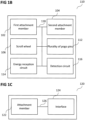
- FIG. 1A shows a dock 100 (in other words: a docking station; in other words: a docking device; in other words: a cradle; in other words: a cradle device) according to various embodiments.
- the dock 100 includes a first attachment member 102 configured to attach to a steering wheel of a car (not shown in FIG. 1A ).
- the dock 100 further includes a second attachment member 104 configured to receive a smart watch module (not shown in FIG. 1A , for example like shown in FIG. 1C or FIG. 1D ).
- the dock 100 further includes a scroll wheel 106 (in other words: a rotatable bezel) configured to provide user input to the computing device, which is provided surrounding a space on which the smart watch module is received, circumferentially around the dock 100, on a rim of the dock 100.
- the first attachment member 102, the second attachment member 104, and the scroll wheel 106 may be coupled with each other, like indicated by lines 108, for example electrically coupled, for example using a line or a cable, and/ or mechanically coupled.
- a docking device for receiving a smart watch module includes a scroll wheel for controlling the smart watch module.
- FIG. 1B shows a dock 110 according to various embodiments.
- the dock 110 similar to the dock 100 shown in FIG. 1A , includes a first attachment member 102 configured to attach to a steering wheel of a car.
- the dock 110 similar to the dock 100 shown in FIG. 1A , further includes a second attachment member 104 configured to receive a smart watch module.
- the dock 110 similar to the dock 100 shown in FIG. 1A , further includes a scroll wheel 106 configured to provide user input to the smart watch module.
- the dock 110 further includes a plurality of pogo pins 112.
- the dock 110 further includes an energy reception circuit 114.
- the dock 110 further includes a detection circuit 116.
- the first attachment member 102, the second attachment member 104, the scroll wheel 106, the plurality of pogo pins 112, the energy reception circuit 114, and the detection circuit 116 may be coupled with each other, like indicated by lines 118, for example electrically coupled, for example using a line or a cable, and/ or mechanically coupled.
- the plurality of pogo pins 112 (which may be contacts under pre-tension, for example using springs, in other words: spring-loaded pins) are configured to provide electrical contact to the smart watch module.
- the detection circuit 116 is configured to detect whether the smart watch module is attached to the dock 110.
- the detection circuit 116 is configured to instruct the smart watch module to change from a watch mode (which may be a normal mode of operation of a smart watch) to a car mode (which may be a mode of operation which allows control of the smart watch module or of a further computing device in (for example wireless) connection with the smart watch module during use in a car) if detection circuit detects that the smart watch module is attached to the dock 110.
- a watch mode which may be a normal mode of operation of a smart watch
- a car mode which may be a mode of operation which allows control of the smart watch module or of a further computing device in (for example wireless) connection with the smart watch module during use in a car
- the scroll wheel 106 may be configured to provide a click function.
- the second attachment member 104 may be configured to receive an at least substantially cylindrically shaped smart watch module.
- FIG. 1C shows a computing device 120.
- the computing device 120 may include an attachment member 122 configured to attach to a dock (not shown in FIG. 1C ; for example a dock as shown in FIG. 1A or FIG. 1B ).
- the computing device 120 may further include an interface 124 configured to receive input from a scroll wheel of the dock.
- the attachment member 122 and the interface 124 may be coupled with each other, like indicated by line 126, for example electrically coupled, for example using a line or a cable, and/ or mechanically coupled.
- FIG. 1D shows a computing device 128.
- the computing device 128 may, similar to the computing device 120 shown in FIG. 1C , include an attachment member 122 configured to attach to a dock.
- the computing device 128 may, similar to the computing device 120 shown in FIG. 1C , further include an interface 124 configured to receive input from a scroll wheel of the dock.
- the computing device 128 may further include a plurality of contacts 130, like will be described in more detail below.
- the computing device 128 may further include a battery 132, like will be described in more detail below.
- the computing device 128 may further include a detection circuit 134, like will be described in more detail below.
- the attachment member 122, the interface 124, the plurality of contacts 130, the battery 132, and the detection circuit 134 may be coupled with each other, like indicated by lines 136, for example electrically coupled, for example using a line or a cable, and/ or mechanically coupled.
- the plurality of contacts 130 may be configured to provide electrical connection to the dock.
- the battery 132 may be configured to provide energy to the computing device 128 and to the dock.
- the detection circuit 134 may be configured to detect whether the computing device 128 is attached to the dock.
- the detection circuit 134 may be configured to switch the computing device 128 from a watch mode to a car mode if the detection circuit 134 detects that the computing device 128 is attached to the dock.
- the computing device 128 (or a housing of the computing device 128) may be at least substantially cylindrically shaped.
- the computing device 128 includes or is included in at least a portion of a smart watch.
- FIG. 1E shows a flow diagram 138 illustrating a method for controlling a dock according to various embodiments.
- the dock has a first attachment member configured to attach to a steering wheel of a car and a second attachment member configured to receive a smart watch module.
- a scroll wheel (of the dock) is controlled to provide user input to the smart watch module.
- the method may further include establishing electrical contact between the dock and the smart watch module using a plurality of pogo pins of the dock.
- the method may further include receiving energy in the dock from the smart watch module.
- the method may further include detecting whether the smart watch module is attached to the dock.
- the method may further include instructing the smart watch module to change from a watch mode to a car mode if it is detected that the smart watch module is attached to the dock.
- the scroll wheel may provide a click function.
- the second attachment member may receive an at least substantially cylindrically shaped computing device.
- FIG. 1F shows a flow diagram 142 illustrating a method for controlling a computing device.
- the computing device may include an attachment member configured to attach to a dock.
- input from a scroll wheel of the dock may be received.
- the method may further include establishing electrical connection between the dock and the computing device using a plurality of contacts of the computing device.
- the method may further include providing energy from a battery of the computing device to the computing device and to the dock.
- the method may further include detecting whether the computing device is attached to the dock.
- the method may further include switching the computing device from a watch mode to a car mode if it is detected that the computing device is attached to the dock.
- the computing device may be at least substantially cylindrically shaped.
- the computing device may include or may be or may be included in at least a portion of a smart watch.
- the holder/dock may only function when the smart watch/disc is inserted into the holder/dock. This may change the smart watch mode to an in-car mode which may allow the user to use the rotatable mechanism on the dock for additional functions.
- the benefit of separating the smart watch and dock may allow the user to access all the functions of a smart watch such as calling, notifications, receiving messages, etc. while on the move.
- the smart watch may be a "disc”, which may be a disc-shaped electronic device including an OLED (organic light emitting diode) touch screen, a rechargeable battery, an accelerometer, a gyro (in other words: a gyroscope), and other components normally found in smart watches. It may run a version of the Android Wear OS (operating system) or any other OS that smart watches may run on.
- the disc may be removable/ detachable from its strap easily so that it can be affixed to the holder/dock.
- a strap may be provided on which the removable disc may be securely affixed, enabling the user to wear it on the wrist like a smart watch.
- a holder for the disc may be provided which may be fixed to the steering wheel of the car, in reach of the user's thumb.
- This holder may include a rotatable mechanism around the rim which may have a tactile feel and may be used for easy scrolling through the app.
- the rotatable mechanism may provide the added dimension of easy scrolling or volume control when the smartwatch is connected to the dock.
- the holder may have pogo pins on the surface which may come into contact with the disc, allowing the disc to detect the scrolling.
- a separate dock may be provided on which the disc may be placed overnight for charging.
- the disc When on the dock, the disc may be vertical for aesthetic purposes.
- an in-car controller dock may be provided which indirectly controls a portable media device by receiving a smart watch which communicates with the media device. This may provide the benefit of the user having all the functions of the smart watch while it is on in-car mode.
- an in-car controller dock may be provided which does not need to be powered or charged because it is powered by the smart watch. This may provide the benefit of not having to charge another separate device. In other words, in contrast to having separate devices which may cause clutter and inconvenience to the user in terms of having to charge them separately, or having to replace the battery on the in-car controller frequently, according to various embodiments, these issues may be avoided.
- a wearable may provide users all the benefits of a smartwatch, a fitness tracker, a companion for the phone, and may double as a convenient, tactile device for use with a car's entertainment system.
- a functional dock may be provided which has a tactile scroll function and which works with another component (for example a smart watch, for example a "disc" of a smart watch).
- This disc may be detached from the accompanying watch strap for the wrist, and affixed into the functional dock which may in turn be attached to the steering wheel of a car using a strap, clamp or other means.
- FIG. 4 shows an illustration 400 of an assembly of the disc 304 into the car dock according to various embodiments.
- the disc 403 may be held by strong magnets in the dock enclosure.
- the disc 304 may be connected to the dock electrically through 3 pogo-pin contacts 210.
- FIG. 5 shows an illustration 500 of the disc base 502, which may be made of stainless steel, according to various embodiments.
- the disc base 502 may include contacts 504, which may correspond to the pogo pins 208 in the dock.
- FIG. 6 shows an exploded view 600 of the car dock according to various embodiments.
- the external enclosure 302, an electronics module 602 with a PCB 804 (printed circuit board) with a rotary encoder 802, an inner enclosure 604 with the pogo pins 210 and strong magnets (not shown in FIG. 6 ), and the rotating bezel 208 are shown.
- FIG. 7 shows an illustration 700 according to various embodiments, wherein the rotating bezel 208 is attached to the rotary encoder 802 through side snaps 702.
- FIG. 8 shows the electronics module 602 including the PCB 804 with main circuitry and with a ring-type rotary encoder 802 according to various embodiments.
- the empty volume within the encoder 802 may make the placement of the disc 304 possible.
- the ring type rotary encoder 802 may include a rotating (or rotatable) ring 806.
- FIG. 9 shows a cross section 900 of the car dock according to various embodiments with the disc 304 assembled (in other words: with the disc 304 provided in (or docked into) the car dock).
- the disc 304 for example in the form of a watch dial
- the inner enclosure 604 the 3 pogo pins 210 connecting the disc 304 to the PCB 804 (wherein the PCB 804 may include the main circuitry), the external enclosure 302, the rotating bezel 208, and the rotary encoder 802 are shown.
- a magnet 902 (or a plurality of magnets 902), for example one or more strong magnets) may be provided in the inner enclosure 604 and may hold down the disc 304.
- the dock enables use of the smartwatch in-car, while providing a tactile and mechanical feature to add another dimension of easy navigation through the connected smart phone.
- the dock may help to ensure lesser distraction while driving, since touch interaction requires the user to look at the screen of the device, unlike a tactile navigation system.
- the use of the dock's mechanical scroll may be customized to match the menu options/function being displayed on the phone.
- the scroll wheel may be used as volume control.
- the scroll wheel may be used to zoom in or zoom out of GPS navigation.
- the scroll wheel may be used to scroll between apps in the main menu (for example horizontally or vertically).
- the scroll wheel may be used to browse contacts on the phone.
- the scroll wheel may be used for any other features that benefit from a mechanical scroll function.
- Various embodiments enable the user to have a tactile scrolling and navigation on a device for easy use in-car, rather than having to rely on the watches' touch screen entirely.
Landscapes
- Engineering & Computer Science (AREA)
- Theoretical Computer Science (AREA)
- General Engineering & Computer Science (AREA)
- Computer Hardware Design (AREA)
- Human Computer Interaction (AREA)
- Physics & Mathematics (AREA)
- General Physics & Mathematics (AREA)
- Combustion & Propulsion (AREA)
- Chemical & Material Sciences (AREA)
- Transportation (AREA)
- Mechanical Engineering (AREA)
- User Interface Of Digital Computer (AREA)
- Electric Clocks (AREA)
- Telephone Function (AREA)
- Acyclic And Carbocyclic Compounds In Medicinal Compositions (AREA)
- Prostheses (AREA)
Description
- The invention generally relates to docks and methods for controlling a dock.
- With the advent of smart watches, users have a device they can carry with them everywhere which can interact with their phone and provide the convenience of not having to remove their phones from their pockets for basic functions. Smart watches that provide the user the option to interact with their cars require the use of smart cars, which are normally more expensive. Additionally, a smart watch cannot (or at least should not) be used while driving, since it requires the user to look away from the road to their watch, potentially causing a safety hazard.
KR 2010 0098743 A KR 2015 0140212 A GB 2 379 286 A JP 2000 241199 A US 2009/059730 A1 discloses a watch. Thus, there may be a need for enhanced devices. - According to the present invention, a dock for a smart watch module having a touch screen is provided. The dock includes the features of claim 1.
- According to the present invention, a method for controlling a dock for a smart watch module having a touch screen is provided. The method includes the features of claim 4.
- In the drawings, like reference characters generally refer to the same parts throughout the different views. The drawings are not necessarily to scale, emphasis instead generally being placed upon illustrating the principles of the invention. The dimensions of the various features or elements may be arbitrarily expanded or reduced for clarity. In the following description, various embodiments of the invention are described with reference to the following drawings, in which:
-
FIG. 1A shows a dock according to various embodiments; -
FIG. 1B shows a dock according to various embodiments; -
FIG. 1C shows a computing device; -
FIG. 1D shows a computing device; -
FIG. 1E shows a flow diagram illustrating a method for controlling a dock according to various embodiments; and -
FIG. 1F shows a flow diagram illustrating a method for controlling a computing device; -
FIG. 2 shows an illustration of a dock according to various embodiments; -
FIG. 3 shows an illustration of a disc in a car dock according to various embodiments; -
FIG. 4 shows an illustration of an assembly of the disc into the car dock according to various embodiments; -
FIG. 5 shows an illustration of the disc base according to various embodiments; -
FIG. 6 shows an exploded view of the car dock according to various embodiments; -
FIG. 7 shows an illustration according to various embodiments, wherein a rotating bezel is attached to a rotary encoder through side snaps; -
FIG. 8 shows an electronics module according to various embodiments; and -
FIG. 9 shows a cross section of a car dock according to various embodiments. - The following detailed description refers to the accompanying drawings that show, by way of illustration, specific details and embodiments in which the invention may be practiced. These embodiments are described in sufficient detail to enable those skilled in the art to practice the invention. Other embodiments may be utilized and structural, and logical changes may be made without departing from the scope of the invention. The various embodiments are not necessarily mutually exclusive.
- In this context, the dock as described in this description may include a memory which is for example used in the processing carried out in the dock. In this context, the computing device as described in this description may include a memory which is for example used in the processing carried out in the computing device. A memory used in the embodiments may be a volatile memory, for example a DRAM (Dynamic Random Access Memory) or a non-volatile memory, for example a PROM (Programmable Read Only Memory), an EPROM (Erasable PROM), EEPROM (Electrically Erasable PROM), or a flash memory, e.g., a floating gate memory, a charge trapping memory, an MRAM (Magnetoresistive Random Access Memory) or a PCRAM (Phase Change Random Access Memory).
- In an embodiment, a "circuit" may be understood as any kind of a logic implementing entity, which may be special purpose circuitry or a processor executing software stored in a memory, firmware, or any combination thereof. Thus, in an embodiment, a "circuit" may be a hard-wired logic circuit or a programmable logic circuit such as a programmable processor, e.g. a microprocessor (e.g. a Complex Instruction Set Computer (CISC) processor or a Reduced Instruction Set Computer (RISC) processor). A "circuit" may also be a processor executing software, e.g. any kind of computer program, e.g. a computer program using a virtual machine code such as e.g. Java. Any other kind of implementation of the respective functions which will be described in more detail below may also be understood as a "circuit" in accordance with an alternative embodiment.
- In the specification the term "comprising" shall be understood to have a broad meaning similar to the term "including" and will be understood to imply the inclusion of a stated integer or step or group of integers or steps but not the exclusion of any other integer or step or group of integers or steps. This definition also applies to variations on the term "comprising" such as "comprise" and "comprises".
- The reference to any prior art in this specification is not, and should not be taken as an acknowledgement or any form of suggestion that the referenced prior art forms part of the common general knowledge in Australia (or any other country).
- In order that the invention may be readily understood and put into practical effect, particular embodiments will now be described by way of examples and not limitations, and with reference to the figures.
- Various embodiments are provided for devices, and various embodiments are provided for methods. It will be understood that basic properties of the devices also hold for the methods and vice versa. Therefore, for sake of brevity, duplicate description of such properties may be omitted.
- It will be understood that any property described herein for a specific device may also hold for any device described herein. It will be understood that any property described herein for a specific method may also hold for any method described herein. Furthermore, it will be understood that for any device or method described herein, not necessarily all the components or steps described must be enclosed in the device or method, but only some (but not all) components or steps may be enclosed.
- The term "coupled" (or "connected") herein may be understood as electrically coupled or as mechanically coupled, for example attached or fixed, or just in contact without any fixation, and it will be understood that both direct coupling or indirect coupling (in other words: coupling without direct contact) may be provided.
- There may be instances of car manufacturers working with smart watch manufacturers to enable control of some functions on their cars using apps on the smart watch, which may desire the cars to be smart themselves in order for the watch/phone to communicate with it.
- It may be best to not use smart watches during driving as they can be a source of distraction during driving. Additionally, a remote controller placed in a position for easy access, such as the steering wheel, which interacts with a smart phone and control a few apps on the phone may be desirable since it also makes it convenient and safer to control the car's entertainment system.
- Some docks that help the user have the smart watch accessible easily on the steering wheel may be available. However, these docks do not provide any additional functionality to the watch in terms of easier navigation. In other words, while docks may be available for smart watches to be affixed onto the steering wheel in easy reach of the driver, they do not provide an intuitive way for the user to interact with them, since their navigation involves the use of touch only.
- Additionally, purpose built in-car controllers may have the disadvantage of requiring a power source, whether using batteries or being rechargeable. According to various embodiments, a functional dock may be provided which does not need any power source, since it may use the power from the smart watch which has been docked into it, when in use.
- According to various embodiments, a way for a user to be able to get another dimension to easier navigation of the smart phone in the car may be provided, for example using the functional dock according to various embodiments, giving easy access to the features that the user might want to access while driving, for example making and receiving calls, music and other media, or GPS (global positioning system) navigation.
- According to various embodiments, a way for the user to use a smart watch as a remote controller for the car's entertainment system may be provided.
- According to various embodiments, a wearable in-car controller may be provided. According to various embodiments, a functional dock for a smart watch for in-car remote control may be provided.
- According to various embodiments, an in-car controller that attaches to a steering wheel of a car and interacts with a smart phone (which may be connected to an entertainment system) that can also be worn on a user's wrist when not driving may give easy access to entertainment without distractions while driving, and may function as a smart watch when not.
- According to various embodiments, an in-car holder/dock for receiving a smartwatch may be provided, wherein the holder/dock may be attached to a steering wheel of car. When the smartwatch (which may be detachable from its strap) is received by the holder, this may allow the driver to utilize all the features of the mobile phone and to control the vehicle entertainment system through the smartwatch. The holder may also have a rotatable bezel to provide added ease of control for the driver such as for scrolling and volume control. Another benefit of the holder may be that it is powered by the smartwatch so it doesn't need to be charged separately.
- According to the invention, a dock with a scroll wheel that can be attached to a steering wheel of a car and that can interact with a purpose built smart watch module is provided. The watch/dock combination may in turn be connected to a smartphone, for example using Bluetooth, which in turn may be connected to the car's entertainment system, or may be used on its own.
- Various embodiments may enable the user to have a smart watch which can also be used as a controller for in-car entertainment. Various embodiments may enable use of the smartwatch while driving, may ensure minimal distractions while driving, from the watch, while also being a convenient way to control the entertainment system of the car, may negate the need to have a smart car since the watch interacts with the phone, which is in turn connected to a compatible car system which can be bought aftermarket, and may enable the user to have tactile feedback while using the disc with the car's steering wheel dock.
-
FIG. 1A shows a dock 100 (in other words: a docking station; in other words: a docking device; in other words: a cradle; in other words: a cradle device) according to various embodiments. Thedock 100 includes afirst attachment member 102 configured to attach to a steering wheel of a car ( not shown inFIG. 1A ). Thedock 100 further includes asecond attachment member 104 configured to receive a smart watch module (not shown inFIG. 1A , for example like shown inFIG. 1C orFIG. 1D ). Thedock 100 further includes a scroll wheel 106 (in other words: a rotatable bezel) configured to provide user input to the computing device, which is provided surrounding a space on which the smart watch module is received, circumferentially around thedock 100, on a rim of thedock 100. Thefirst attachment member 102, thesecond attachment member 104, and thescroll wheel 106 may be coupled with each other, like indicated bylines 108, for example electrically coupled, for example using a line or a cable, and/ or mechanically coupled. - In other words, according to the invention, a docking device for receiving a smart watch module includes a scroll wheel for controlling the smart watch module.
-
FIG. 1B shows adock 110 according to various embodiments. Thedock 110, similar to thedock 100 shown inFIG. 1A , includes afirst attachment member 102 configured to attach to a steering wheel of a car. Thedock 110, similar to thedock 100 shown inFIG. 1A , further includes asecond attachment member 104 configured to receive a smart watch module. Thedock 110, similar to thedock 100 shown inFIG. 1A , further includes ascroll wheel 106 configured to provide user input to the smart watch module. Thedock 110 further includes a plurality of pogo pins 112. Thedock 110 further includes anenergy reception circuit 114. Thedock 110 further includes adetection circuit 116. Thefirst attachment member 102, thesecond attachment member 104, thescroll wheel 106, the plurality of pogo pins 112, theenergy reception circuit 114, and thedetection circuit 116 may be coupled with each other, like indicated bylines 118, for example electrically coupled, for example using a line or a cable, and/ or mechanically coupled. - The plurality of pogo pins 112 (which may be contacts under pre-tension, for example using springs, in other words: spring-loaded pins) are configured to provide electrical contact to the smart watch module.
- The
energy reception circuit 114 may be configured to receive energy from the smart watch module. - The
detection circuit 116 is configured to detect whether the smart watch module is attached to thedock 110. - According to various embodiments, the
detection circuit 116 is configured to instruct the smart watch module to change from a watch mode (which may be a normal mode of operation of a smart watch) to a car mode (which may be a mode of operation which allows control of the smart watch module or of a further computing device in (for example wireless) connection with the smart watch module during use in a car) if detection circuit detects that the smart watch module is attached to thedock 110. - According to various embodiments, the
scroll wheel 106 may be configured to provide a click function. - According to various embodiments, the
second attachment member 104 may be configured to receive an at least substantially cylindrically shaped smart watch module. -
FIG. 1C shows acomputing device 120. Thecomputing device 120 may include anattachment member 122 configured to attach to a dock (not shown inFIG. 1C ; for example a dock as shown inFIG. 1A orFIG. 1B ). Thecomputing device 120 may further include aninterface 124 configured to receive input from a scroll wheel of the dock. Theattachment member 122 and theinterface 124 may be coupled with each other, like indicated byline 126, for example electrically coupled, for example using a line or a cable, and/ or mechanically coupled. -
FIG. 1D shows acomputing device 128. Thecomputing device 128 may, similar to thecomputing device 120 shown inFIG. 1C , include anattachment member 122 configured to attach to a dock. Thecomputing device 128 may, similar to thecomputing device 120 shown inFIG. 1C , further include aninterface 124 configured to receive input from a scroll wheel of the dock. Thecomputing device 128 may further include a plurality ofcontacts 130, like will be described in more detail below. Thecomputing device 128 may further include abattery 132, like will be described in more detail below. Thecomputing device 128 may further include adetection circuit 134, like will be described in more detail below. Theattachment member 122, theinterface 124, the plurality ofcontacts 130, thebattery 132, and thedetection circuit 134 may be coupled with each other, like indicated bylines 136, for example electrically coupled, for example using a line or a cable, and/ or mechanically coupled. - The plurality of
contacts 130 may be configured to provide electrical connection to the dock. - The
battery 132 may be configured to provide energy to thecomputing device 128 and to the dock. - The
detection circuit 134 may be configured to detect whether thecomputing device 128 is attached to the dock. - The
detection circuit 134 may be configured to switch thecomputing device 128 from a watch mode to a car mode if thedetection circuit 134 detects that thecomputing device 128 is attached to the dock. - The computing device 128 (or a housing of the computing device 128) may be at least substantially cylindrically shaped.
- The
computing device 128 includes or is included in at least a portion of a smart watch. -
FIG. 1E shows a flow diagram 138 illustrating a method for controlling a dock according to various embodiments. The dock has a first attachment member configured to attach to a steering wheel of a car and a second attachment member configured to receive a smart watch module. In 140, a scroll wheel (of the dock) is controlled to provide user input to the smart watch module. - The method may further include establishing electrical contact between the dock and the smart watch module using a plurality of pogo pins of the dock.
- The method may further include receiving energy in the dock from the smart watch module.
- The method may further include detecting whether the smart watch module is attached to the dock.
- According to various embodiments, the method may further include instructing the smart watch module to change from a watch mode to a car mode if it is detected that the smart watch module is attached to the dock.
- According to various embodiments, the scroll wheel may provide a click function.
- According to various embodiments, the second attachment member may receive an at least substantially cylindrically shaped computing device.
-
FIG. 1F shows a flow diagram 142 illustrating a method for controlling a computing device. The computing device may include an attachment member configured to attach to a dock. In 144, input from a scroll wheel of the dock may be received. - The method may further include establishing electrical connection between the dock and the computing device using a plurality of contacts of the computing device.
- The method may further include providing energy from a battery of the computing device to the computing device and to the dock.
- The method may further include detecting whether the computing device is attached to the dock.
- The method may further include switching the computing device from a watch mode to a car mode if it is detected that the computing device is attached to the dock.
- The computing device may be at least substantially cylindrically shaped.
- The computing device may include or may be or may be included in at least a portion of a smart watch.
- According to various embodiments, the holder/dock may only function when the smart watch/disc is inserted into the holder/dock. This may change the smart watch mode to an in-car mode which may allow the user to use the rotatable mechanism on the dock for additional functions. The benefit of separating the smart watch and dock may allow the user to access all the functions of a smart watch such as calling, notifications, receiving messages, etc. while on the move.
- The smart watch may be a "disc", which may be a disc-shaped electronic device including an OLED (organic light emitting diode) touch screen, a rechargeable battery, an accelerometer, a gyro (in other words: a gyroscope), and other components normally found in smart watches. It may run a version of the Android Wear OS (operating system) or any other OS that smart watches may run on. The disc may be removable/ detachable from its strap easily so that it can be affixed to the holder/dock.
- According to various embodiments, a strap may be provided on which the removable disc may be securely affixed, enabling the user to wear it on the wrist like a smart watch.
- According to various embodiments, a holder for the disc may be provided which may be fixed to the steering wheel of the car, in reach of the user's thumb. This holder may include a rotatable mechanism around the rim which may have a tactile feel and may be used for easy scrolling through the app. The rotatable mechanism may provide the added dimension of easy scrolling or volume control when the smartwatch is connected to the dock. The holder may have pogo pins on the surface which may come into contact with the disc, allowing the disc to detect the scrolling.
- According to various embodiments, a separate dock may be provided on which the disc may be placed overnight for charging. When on the dock, the disc may be vertical for aesthetic purposes.
- According to various embodiments, an in-car controller dock may be provided which indirectly controls a portable media device by receiving a smart watch which communicates with the media device. This may provide the benefit of the user having all the functions of the smart watch while it is on in-car mode.
- According to various embodiments, an in-car controller dock may be provided which does not need to be powered or charged because it is powered by the smart watch. This may provide the benefit of not having to charge another separate device. In other words, in contrast to having separate devices which may cause clutter and inconvenience to the user in terms of having to charge them separately, or having to replace the battery on the in-car controller frequently, according to various embodiments, these issues may be avoided.
- According to various embodiments, a wearable (in other words: a wearable device) may provide users all the benefits of a smartwatch, a fitness tracker, a companion for the phone, and may double as a convenient, tactile device for use with a car's entertainment system.
- According to various embodiments, the functional dock may be used as an attachment with the user's watch on their wrist (instead of on the steering wheel) for tactile feel.
- According to various embodiments, a functional dock may be provided which has a tactile scroll function and which works with another component (for example a smart watch, for example a "disc" of a smart watch). This disc may be detached from the accompanying watch strap for the wrist, and affixed into the functional dock which may in turn be attached to the steering wheel of a car using a strap, clamp or other means.
- The dock has pogo pins which may come into contact with the disc when it is plugged in. This may allow the dock to interact with the smart watch. This may also let the smart phone detect when the disc is plugged into the dock, and may allow it to take appropriate action, like launching a unifying in-car app, entertainment app, navigation, or other similar app relevant to in-car usage by the driver. The dock may draw the required power from the watch for its own functioning.
-
FIG. 2 shows anillustration 200 of adock 204 according to various embodiments, onto which a disc is not affixed. Thedock 204 can be attached to asteering wheel 202 of a car using astrap 206 or any other mechanism to keep thedock 204 in place on thesteering wheel 202. Thedock 204 includes pogo pins 210 to connect with the disc when the disc is place into (or onto) thedock 204. A tactile scroll function is provided, using ascroll wheel 208 around a rim of thedock 204. -
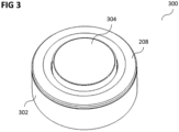
FIG. 3 shows anillustration 300 of adisc 304 in a car dock according to various embodiments. Anenclosure 302 may surround the disc 304 (for example in the form of a watch dial) and therotating bezel 208. -
FIG. 4 shows anillustration 400 of an assembly of thedisc 304 into the car dock according to various embodiments. The disc 403 may be held by strong magnets in the dock enclosure. Thedisc 304 may be connected to the dock electrically through 3 pogo-pin contacts 210. -
FIG. 5 shows anillustration 500 of thedisc base 502, which may be made of stainless steel, according to various embodiments. Thedisc base 502 may includecontacts 504, which may correspond to the pogo pins 208 in the dock. -
FIG. 6 shows an explodedview 600 of the car dock according to various embodiments. Theexternal enclosure 302, anelectronics module 602 with a PCB 804 (printed circuit board) with arotary encoder 802, aninner enclosure 604 with the pogo pins 210 and strong magnets (not shown inFIG. 6 ), and therotating bezel 208 are shown. -
FIG. 7 shows anillustration 700 according to various embodiments, wherein therotating bezel 208 is attached to therotary encoder 802 through side snaps 702. -
FIG. 8 shows theelectronics module 602 including thePCB 804 with main circuitry and with a ring-type rotary encoder 802 according to various embodiments. The empty volume within theencoder 802 may make the placement of thedisc 304 possible. The ringtype rotary encoder 802 may include a rotating (or rotatable)ring 806. -
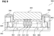
FIG. 9 shows across section 900 of the car dock according to various embodiments with thedisc 304 assembled (in other words: with thedisc 304 provided in (or docked into) the car dock). The disc 304 (for example in the form of a watch dial), theinner enclosure 604, the 3 pogo pins 210 connecting thedisc 304 to the PCB 804 (wherein thePCB 804 may include the main circuitry), theexternal enclosure 302, therotating bezel 208, and therotary encoder 802 are shown. A magnet 902 (or a plurality of magnets 902), for example one or more strong magnets) may be provided in theinner enclosure 604 and may hold down thedisc 304. - It will be understood that in
FIG. 3 to FIG. 9 , all elements except thedisc 304 are elements of the dock, for example of the car dock. - The dock enables use of the smartwatch in-car, while providing a tactile and mechanical feature to add another dimension of easy navigation through the connected smart phone. The dock may help to ensure lesser distraction while driving, since touch interaction requires the user to look at the screen of the device, unlike a tactile navigation system.
- According to various embodiments, the use of the dock's mechanical scroll (in other words: the user of the mechanical scroll wheel) may be customized to match the menu options/function being displayed on the phone. According to various embodiments, if the user is accessing the music feature or is in a call, the scroll wheel may be used as volume control. According to various embodiments, the scroll wheel may be used to zoom in or zoom out of GPS navigation. According to various embodiments, the scroll wheel may be used to scroll between apps in the main menu (for example horizontally or vertically). According to various embodiments, the scroll wheel may be used to browse contacts on the phone. According to various embodiments, the scroll wheel may be used for any other features that benefit from a mechanical scroll function.
- Various embodiments enable the user to have a tactile scrolling and navigation on a device for easy use in-car, rather than having to rely on the watches' touch screen entirely.
Claims (6)
- A dock (100, 110, 204) for a smart watch module (120, 128) having a touch screen, the dock (100, 110, 2014) comprising:a first attachment member (102) configured to attach to a steering wheel of a car;a second attachment member (104) configured to receive the smart watch module (120, 128) on a surface within a space of the second attachment member (104);a plurality of pogo pins (112, 210) on the surface of the second attachment member (104), the plurality of pogo pins (112, 210) configured to provide electrical contact to the smart watch module (120, 128);a scroll wheel (106) being a rotatable bezel provided circumferentially around the dock (100, 110, 204) on a rim of the dock (100, 110, 204) so as to surround the space of the second attachment member (104), the scroll wheel (106) configured to provide user input to the smart watch module (120, 128) through the plurality of pogo pins (112, 210) for controlling the smart watch module (120, 128) to access functions of the smart watch module (120, 128) via a tactile scroll function provided by the scroll wheel (106) without requiring touch interaction with the touch screen of the smart watch module (120, 128);a detection circuit (116) configured to detect whether the smart watch module (120, 128) is received in the dock (100, 110, 204), wherein the detection circuit (116) is configured to instruct the smart watch module (120, 128) to enter into a car mode to allow control of the smart watch module (120, 128) using the scroll wheel (106) if the detection circuit (116) detects that the smart watch module (120, 128) is received in the dock (100, 110, 204); andan energy reception circuit (114) configured to receive energy from the smart watch module (120, 128) through the plurality of pogo pins (112, 210), when the smart watch module (120, 128) is received on the surface of the second attachment member (104), so as to power the dock (100, 110, 204) by the smart watch module (120, 128) for functioning of the scroll wheel (106) and the detection circuit (116) of the dock (100, 110, 204).
- The dock (100, 110, 204) of claim 1, wherein the scroll wheel (106) is configured to provide a click function.
- The dock (100, 110, 204) of claim 1 or claim 2,
wherein the second attachment member (104) is configured to receive a cylindrically shaped computing device (120, 128). - A method for controlling a dock (100, 110, 204) for a smart watch module (120, 128) having a touch screen, the dock (100, 110, 2014) comprising a first attachment member (102) configured to attach to a steering wheel of a car, and a second attachment member (104) configured to receive the smart watch module (120, 128) on a surface within a space of the second attachment member (104), the method comprising:establishing electrical contact between the dock (100, 110, 204) and the smart watch module (120, 128) using a plurality of pogo pins (112, 210) on the surface of the second attachment member (104), the plurality of pogo pins (112, 210) configured to provide electrical contact to the smart watch module (120, 128);receiving energy in the dock (100, 110, 204) from the smart watch module (120, 128) through the plurality of pogo pins (112, 210), when the smart watch module (120, 128) is received on the surface of the second attachment member (104), so as to power the dock (100, 110, 204) by the smart watch module (120, 128) for functioning of a scroll wheel (106) and a detection circuit (116) of the dock (100, 110, 204);detecting, via the detection circuit (116), whether the smart watch module (120, 128) is attached to the dock (100, 110, 204);instructing, via the detection circuit (116), the smart watch module (120, 128) to enter into a car mode to allow control of the smart watch module (120, 128) using the scroll wheel (106) if it is detected that the smart watch module (120, 128) is attached to the dock (100, 110, 204); andproviding a tactile scroll function via the scroll wheel (106) to provide user input to the smart watch module (120, 128) through the plurality of pogo pins (112, 210) for controlling the smart watch module (120, 128) to access functions of the smart watch module (120, 128) without requiring touch interaction with the touch screen of the smart watch module (120, 128), the scroll wheel (106) being a rotatable bezel provided circumferentially around the dock (100, 110, 204) on a rim of the dock (100, 110, 204) so as to surround the space of the second attachment member (104) .
- The method of claim 4, wherein the scroll wheel (106) provides a click function.
- The method of claim 4 or claim 5,
wherein the second attachment member (104) receives a cylindrically shaped smart watch module (120, 128).
Applications Claiming Priority (1)
| Application Number | Priority Date | Filing Date | Title |
|---|---|---|---|
| PCT/SG2016/050139 WO2017164808A1 (en) | 2016-03-24 | 2016-03-24 | Docks, computing devices, methods for controlling a dock, and methods for controlling a computing device |
Publications (3)
| Publication Number | Publication Date |
|---|---|
| EP3433681A1 EP3433681A1 (en) | 2019-01-30 |
| EP3433681A4 EP3433681A4 (en) | 2019-03-27 |
| EP3433681B1 true EP3433681B1 (en) | 2025-03-12 |
Family
ID=59900689
Family Applications (1)
| Application Number | Title | Priority Date | Filing Date |
|---|---|---|---|
| EP16895643.1A Active EP3433681B1 (en) | 2016-03-24 | 2016-03-24 | Docks, computing devices, methods for controlling a dock, and methods for controlling a computing device |
Country Status (7)
| Country | Link |
|---|---|
| US (1) | US10747266B2 (en) |
| EP (1) | EP3433681B1 (en) |
| CN (1) | CN109478040B (en) |
| AU (1) | AU2016398408B2 (en) |
| SG (1) | SG11201808099TA (en) |
| TW (1) | TWI730070B (en) |
| WO (1) | WO2017164808A1 (en) |
Families Citing this family (2)
| Publication number | Priority date | Publication date | Assignee | Title |
|---|---|---|---|---|
| KR102594718B1 (en) * | 2015-11-20 | 2023-10-26 | 하만인터내셔날인더스트리스인코포레이티드 | Dynamic reconfigurable display knob |
| KR102152015B1 (en) * | 2018-10-18 | 2020-09-04 | (주)에이아이솔루션 | Connecting sled system for mobile devices |
Family Cites Families (34)
| Publication number | Priority date | Publication date | Assignee | Title |
|---|---|---|---|---|
| JP3373637B2 (en) * | 1994-02-25 | 2003-02-04 | 株式会社キャットアイ | Engagement structure |
| WO1997002513A1 (en) * | 1995-07-05 | 1997-01-23 | Motorola Inc. | Conformal power supply |
| JP2000241199A (en) | 1999-02-24 | 2000-09-08 | Seiko Epson Corp | Information processing apparatus and information input method of information processing apparatus |
| US6556222B1 (en) | 2000-06-30 | 2003-04-29 | International Business Machines Corporation | Bezel based input mechanism and user interface for a smart watch |
| GB2379286A (en) | 2001-08-29 | 2003-03-05 | Innomind Internat Ltd | Electronic multi-function watch |
| US8768286B2 (en) | 2001-10-24 | 2014-07-01 | Mouhamad Ahmad Naboulsi | Hands on steering wheel vehicle safety control system |
| US7259793B2 (en) * | 2002-03-26 | 2007-08-21 | Eastman Kodak Company | Display module for supporting a digital image display device |
| US7221331B2 (en) * | 2003-05-05 | 2007-05-22 | Microsoft Corporation | Method and system for auxiliary display of information for a computing device |
| US7068151B2 (en) | 2003-05-14 | 2006-06-27 | Giles Samuel K | Vehicle security system |
| US20070050061A1 (en) | 2005-08-31 | 2007-03-01 | Andre Klein | Audio player remote control system |
| US7589496B2 (en) * | 2006-06-02 | 2009-09-15 | Microsoft Corporation | User input device charging system |
| US7778118B2 (en) | 2007-08-28 | 2010-08-17 | Garmin Ltd. | Watch device having touch-bezel user interface |
| KR20100098743A (en) | 2009-03-02 | 2010-09-10 | (주)와이더 | Smart cradle for car |
| US20110263293A1 (en) * | 2010-04-22 | 2011-10-27 | Ford Global Technologies, Llc | Mobile device interface for use in a vehicle |
| US8177182B1 (en) | 2011-01-07 | 2012-05-15 | Apple Inc. | Wireless remote control device for a portable media device |
| US8787006B2 (en) * | 2011-01-31 | 2014-07-22 | Apple Inc. | Wrist-worn electronic device and methods therefor |
| US9740237B2 (en) * | 2012-03-30 | 2017-08-22 | Hewlett-Packard Development Company, L.P. | Assembly for removable display and input devices |
| WO2014047695A2 (en) | 2012-09-25 | 2014-04-03 | Kazamias Christian Christos | "personalized emergency, safety & rules based interactive alert notification system |
| EP2730982B1 (en) * | 2012-11-08 | 2019-05-08 | ETA SA Manufacture Horlogère Suisse | Battery attachment with improved contact |
| US8994827B2 (en) * | 2012-11-20 | 2015-03-31 | Samsung Electronics Co., Ltd | Wearable electronic device |
| DE102013211019A1 (en) | 2013-06-13 | 2014-12-18 | Ford Global Technologies, Llc | Multimedia installation unit for a motor vehicle |
| US9424047B2 (en) | 2013-08-05 | 2016-08-23 | Harman International Industries, Incorporated | System and methods for an in-vehicle computing system |
| US9244492B2 (en) * | 2013-09-09 | 2016-01-26 | Apple Inc. | Docking station with audio output |
| US9760698B2 (en) | 2013-09-17 | 2017-09-12 | Toyota Motor Sales, U.S.A., Inc. | Integrated wearable article for interactive vehicle control system |
| US20150116927A1 (en) * | 2013-10-28 | 2015-04-30 | ACCO Brands Corporation | Portable electronic device case, folio, and dock |
| US9481326B2 (en) | 2013-11-06 | 2016-11-01 | Harman International Industries, Incorporated | Adapting vehicle systems based on wearable devices |
| CN106030447B (en) * | 2014-02-28 | 2019-09-10 | 苹果公司 | Product Demonstration Fixtures for Portable Electronics |
| KR101554188B1 (en) | 2014-06-05 | 2015-09-18 | 엘지전자 주식회사 | Wearable device and method for controlling the same |
| KR20150140212A (en) | 2014-06-05 | 2015-12-15 | 삼성전자주식회사 | A wearable device, main unit of the wearable device, fixing unit of the wearable device and control method thereof |
| US20150358043A1 (en) * | 2014-06-05 | 2015-12-10 | Samsung Electronics Co., Ltd. | Wearable device, main unit of wearable device, fixing unit of wearable device, and control method of wearable device |
| US9754479B2 (en) * | 2014-06-25 | 2017-09-05 | Microsoft Technology Licensing, Llc | Remote control of a mobile computing device with an auxiliary device |
| KR102232279B1 (en) | 2014-08-25 | 2021-03-26 | 삼성전자주식회사 | Cradle for electronic device |
| CN204137095U (en) | 2014-08-26 | 2015-02-04 | 长沙联远电子科技有限公司 | On-vehicle control apparatus and bearing circle |
| CN205080368U (en) * | 2015-07-26 | 2016-03-09 | 南安智能蓝工业设计有限公司 | Foldable car intelligence wrist -watch |
-
2016
- 2016-03-24 SG SG11201808099TA patent/SG11201808099TA/en unknown
- 2016-03-24 CN CN201680085665.4A patent/CN109478040B/en active Active
- 2016-03-24 US US16/087,619 patent/US10747266B2/en active Active
- 2016-03-24 WO PCT/SG2016/050139 patent/WO2017164808A1/en not_active Ceased
- 2016-03-24 EP EP16895643.1A patent/EP3433681B1/en active Active
- 2016-03-24 AU AU2016398408A patent/AU2016398408B2/en active Active
-
2017
- 2017-03-22 TW TW106109553A patent/TWI730070B/en active
Also Published As
| Publication number | Publication date |
|---|---|
| TW201737564A (en) | 2017-10-16 |
| TWI730070B (en) | 2021-06-11 |
| SG11201808099TA (en) | 2018-10-30 |
| AU2016398408B2 (en) | 2021-12-02 |
| EP3433681A1 (en) | 2019-01-30 |
| CN109478040A (en) | 2019-03-15 |
| US20190101956A1 (en) | 2019-04-04 |
| CN109478040B (en) | 2021-11-26 |
| AU2016398408A1 (en) | 2018-10-11 |
| US10747266B2 (en) | 2020-08-18 |
| EP3433681A4 (en) | 2019-03-27 |
| WO2017164808A1 (en) | 2017-09-28 |
Similar Documents
| Publication | Publication Date | Title |
|---|---|---|
| US11294473B2 (en) | Wrist-worn electronic device and methods therefor | |
| EP2750361B1 (en) | Controlling an application parameter | |
| EP2920904B1 (en) | Adaptive antenna selection | |
| CN113253856A (en) | Stylus and electronic device assembly | |
| US20160357324A1 (en) | Protective case with cover for wearable electronic device | |
| CN105929935A (en) | Method And Apparatus For Activating Applications Based On Rotation Input | |
| KR20100090800A (en) | Human interface input acceleration system | |
| KR20130009857A (en) | Smart method and device for adaptive user interface experiences | |
| JP6169238B1 (en) | Electronic device, program, and control method | |
| AU2016398408B2 (en) | Docks, computing devices, methods for controlling a dock, and methods for controlling a computing device | |
| JP2017027465A (en) | Electronic device system, electronic device cover and electronic device | |
| US8766593B2 (en) | Electronic device and method with rollable display | |
| KR20180070243A (en) | Input apparatus in electronic device and control method thereof | |
| KR102559974B1 (en) | Electronic device for displaying information regarding stylus pen and method thereof | |
| KR20150061420A (en) | Smart watch and operation method thereof | |
| KR20170045528A (en) | Monitor system with multimedia mirroring | |
| US20150017963A1 (en) | Method, electronic device, and computer readable recording medium for providing location based services | |
| JP6568269B2 (en) | Electronic device, program, and control method | |
| JP6221001B1 (en) | Electronic device, program, and control method | |
| JP6374585B2 (en) | Electronic device, program, and control method | |
| KR20160148442A (en) | The smartphones having a function of displaying using a backup battery | |
| CN116736990B (en) | Stylus pen and electronic device components | |
| KR20210111032A (en) | Electronic device display state of alignment for wireless charging | |
| KR20140096452A (en) | Mobile device, Specifying function practicing method thereof and Saving device having that method |
Legal Events
| Date | Code | Title | Description |
|---|---|---|---|
| STAA | Information on the status of an ep patent application or granted ep patent |
Free format text: STATUS: THE INTERNATIONAL PUBLICATION HAS BEEN MADE |
|
| PUAI | Public reference made under article 153(3) epc to a published international application that has entered the european phase |
Free format text: ORIGINAL CODE: 0009012 |
|
| STAA | Information on the status of an ep patent application or granted ep patent |
Free format text: STATUS: REQUEST FOR EXAMINATION WAS MADE |
|
| 17P | Request for examination filed |
Effective date: 20180924 |
|
| AK | Designated contracting states |
Kind code of ref document: A1 Designated state(s): AL AT BE BG CH CY CZ DE DK EE ES FI FR GB GR HR HU IE IS IT LI LT LU LV MC MK MT NL NO PL PT RO RS SE SI SK SM TR |
|
| AX | Request for extension of the european patent |
Extension state: BA ME |
|
| A4 | Supplementary search report drawn up and despatched |
Effective date: 20190227 |
|
| RIC1 | Information provided on ipc code assigned before grant |
Ipc: G04G 17/02 20060101AFI20190221BHEP Ipc: G06F 1/16 20060101ALI20190221BHEP Ipc: G04G 17/08 20060101ALI20190221BHEP Ipc: G04B 47/00 20060101ALI20190221BHEP |
|
| DAV | Request for validation of the european patent (deleted) | ||
| DAX | Request for extension of the european patent (deleted) | ||
| STAA | Information on the status of an ep patent application or granted ep patent |
Free format text: STATUS: EXAMINATION IS IN PROGRESS |
|
| 17Q | First examination report despatched |
Effective date: 20200302 |
|
| RAP3 | Party data changed (applicant data changed or rights of an application transferred) |
Owner name: RAZER (ASIA-PACIFIC) PTE. LTD. |
|
| P01 | Opt-out of the competence of the unified patent court (upc) registered |
Effective date: 20230327 |
|
| GRAP | Despatch of communication of intention to grant a patent |
Free format text: ORIGINAL CODE: EPIDOSNIGR1 |
|
| STAA | Information on the status of an ep patent application or granted ep patent |
Free format text: STATUS: GRANT OF PATENT IS INTENDED |
|
| INTG | Intention to grant announced |
Effective date: 20241004 |
|
| RIN1 | Information on inventor provided before grant (corrected) |
Inventor name: KWEK, SZE KHIANG REX Inventor name: LEE, KAH YONG Inventor name: CHONG, BOON SIM Inventor name: BREINHOLT, GREG Inventor name: LIANG, JEFFREY CHEE CHENG Inventor name: CHAN, CHEE OEI Inventor name: TAN, MIN-LIANG Inventor name: UNNIKRISHNAN, SREENATH Inventor name: LIEN, JIAN YAO |
|
| GRAS | Grant fee paid |
Free format text: ORIGINAL CODE: EPIDOSNIGR3 |
|
| GRAA | (expected) grant |
Free format text: ORIGINAL CODE: 0009210 |
|
| STAA | Information on the status of an ep patent application or granted ep patent |
Free format text: STATUS: THE PATENT HAS BEEN GRANTED |
|
| AK | Designated contracting states |
Kind code of ref document: B1 Designated state(s): AL AT BE BG CH CY CZ DE DK EE ES FI FR GB GR HR HU IE IS IT LI LT LU LV MC MK MT NL NO PL PT RO RS SE SI SK SM TR |
|
| REG | Reference to a national code |
Ref country code: GB Ref legal event code: FG4D |
|
| REG | Reference to a national code |
Ref country code: CH Ref legal event code: EP |
|
| REG | Reference to a national code |
Ref country code: DE Ref legal event code: R096 Ref document number: 602016091558 Country of ref document: DE |
|
| REG | Reference to a national code |
Ref country code: IE Ref legal event code: FG4D |
|
| PG25 | Lapsed in a contracting state [announced via postgrant information from national office to epo] |
Ref country code: RS Free format text: LAPSE BECAUSE OF FAILURE TO SUBMIT A TRANSLATION OF THE DESCRIPTION OR TO PAY THE FEE WITHIN THE PRESCRIBED TIME-LIMIT Effective date: 20250612 |
|
| PG25 | Lapsed in a contracting state [announced via postgrant information from national office to epo] |
Ref country code: FI Free format text: LAPSE BECAUSE OF FAILURE TO SUBMIT A TRANSLATION OF THE DESCRIPTION OR TO PAY THE FEE WITHIN THE PRESCRIBED TIME-LIMIT Effective date: 20250312 |
|
| PG25 | Lapsed in a contracting state [announced via postgrant information from national office to epo] |
Ref country code: ES Free format text: LAPSE BECAUSE OF FAILURE TO SUBMIT A TRANSLATION OF THE DESCRIPTION OR TO PAY THE FEE WITHIN THE PRESCRIBED TIME-LIMIT Effective date: 20250312 |
|
| REG | Reference to a national code |
Ref country code: LT Ref legal event code: MG9D |
|
| PG25 | Lapsed in a contracting state [announced via postgrant information from national office to epo] |
Ref country code: NO Free format text: LAPSE BECAUSE OF FAILURE TO SUBMIT A TRANSLATION OF THE DESCRIPTION OR TO PAY THE FEE WITHIN THE PRESCRIBED TIME-LIMIT Effective date: 20250612 |
|
| PG25 | Lapsed in a contracting state [announced via postgrant information from national office to epo] |
Ref country code: HR Free format text: LAPSE BECAUSE OF FAILURE TO SUBMIT A TRANSLATION OF THE DESCRIPTION OR TO PAY THE FEE WITHIN THE PRESCRIBED TIME-LIMIT Effective date: 20250312 |
|
| REG | Reference to a national code |
Ref country code: NL Ref legal event code: MP Effective date: 20250312 |
|
| PG25 | Lapsed in a contracting state [announced via postgrant information from national office to epo] |
Ref country code: LV Free format text: LAPSE BECAUSE OF FAILURE TO SUBMIT A TRANSLATION OF THE DESCRIPTION OR TO PAY THE FEE WITHIN THE PRESCRIBED TIME-LIMIT Effective date: 20250312 |
|
| PG25 | Lapsed in a contracting state [announced via postgrant information from national office to epo] |
Ref country code: GR Free format text: LAPSE BECAUSE OF FAILURE TO SUBMIT A TRANSLATION OF THE DESCRIPTION OR TO PAY THE FEE WITHIN THE PRESCRIBED TIME-LIMIT Effective date: 20250613 Ref country code: BG Free format text: LAPSE BECAUSE OF FAILURE TO SUBMIT A TRANSLATION OF THE DESCRIPTION OR TO PAY THE FEE WITHIN THE PRESCRIBED TIME-LIMIT Effective date: 20250312 |
|
| REG | Reference to a national code |
Ref country code: AT Ref legal event code: MK05 Ref document number: 1775503 Country of ref document: AT Kind code of ref document: T Effective date: 20250312 |
|
| PG25 | Lapsed in a contracting state [announced via postgrant information from national office to epo] |
Ref country code: NL Free format text: LAPSE BECAUSE OF FAILURE TO SUBMIT A TRANSLATION OF THE DESCRIPTION OR TO PAY THE FEE WITHIN THE PRESCRIBED TIME-LIMIT Effective date: 20250312 |
|
| PG25 | Lapsed in a contracting state [announced via postgrant information from national office to epo] |
Ref country code: SE Free format text: LAPSE BECAUSE OF FAILURE TO SUBMIT A TRANSLATION OF THE DESCRIPTION OR TO PAY THE FEE WITHIN THE PRESCRIBED TIME-LIMIT Effective date: 20250312 |
|
| PG25 | Lapsed in a contracting state [announced via postgrant information from national office to epo] |
Ref country code: SM Free format text: LAPSE BECAUSE OF FAILURE TO SUBMIT A TRANSLATION OF THE DESCRIPTION OR TO PAY THE FEE WITHIN THE PRESCRIBED TIME-LIMIT Effective date: 20250312 |
|
| PG25 | Lapsed in a contracting state [announced via postgrant information from national office to epo] |
Ref country code: PT Free format text: LAPSE BECAUSE OF FAILURE TO SUBMIT A TRANSLATION OF THE DESCRIPTION OR TO PAY THE FEE WITHIN THE PRESCRIBED TIME-LIMIT Effective date: 20250714 |
|
| PG25 | Lapsed in a contracting state [announced via postgrant information from national office to epo] |
Ref country code: PL Free format text: LAPSE BECAUSE OF FAILURE TO SUBMIT A TRANSLATION OF THE DESCRIPTION OR TO PAY THE FEE WITHIN THE PRESCRIBED TIME-LIMIT Effective date: 20250312 Ref country code: IT Free format text: LAPSE BECAUSE OF FAILURE TO SUBMIT A TRANSLATION OF THE DESCRIPTION OR TO PAY THE FEE WITHIN THE PRESCRIBED TIME-LIMIT Effective date: 20250312 |
|
| PG25 | Lapsed in a contracting state [announced via postgrant information from national office to epo] |
Ref country code: AT Free format text: LAPSE BECAUSE OF FAILURE TO SUBMIT A TRANSLATION OF THE DESCRIPTION OR TO PAY THE FEE WITHIN THE PRESCRIBED TIME-LIMIT Effective date: 20250312 |
|
| PG25 | Lapsed in a contracting state [announced via postgrant information from national office to epo] |
Ref country code: EE Free format text: LAPSE BECAUSE OF FAILURE TO SUBMIT A TRANSLATION OF THE DESCRIPTION OR TO PAY THE FEE WITHIN THE PRESCRIBED TIME-LIMIT Effective date: 20250312 Ref country code: CZ Free format text: LAPSE BECAUSE OF FAILURE TO SUBMIT A TRANSLATION OF THE DESCRIPTION OR TO PAY THE FEE WITHIN THE PRESCRIBED TIME-LIMIT Effective date: 20250312 |
|
| PG25 | Lapsed in a contracting state [announced via postgrant information from national office to epo] |
Ref country code: RO Free format text: LAPSE BECAUSE OF FAILURE TO SUBMIT A TRANSLATION OF THE DESCRIPTION OR TO PAY THE FEE WITHIN THE PRESCRIBED TIME-LIMIT Effective date: 20250312 |
|
| REG | Reference to a national code |
Ref country code: CH Ref legal event code: H13 Free format text: ST27 STATUS EVENT CODE: U-0-0-H10-H13 (AS PROVIDED BY THE NATIONAL OFFICE) Effective date: 20251023 |
|
| PG25 | Lapsed in a contracting state [announced via postgrant information from national office to epo] |
Ref country code: SK Free format text: LAPSE BECAUSE OF FAILURE TO SUBMIT A TRANSLATION OF THE DESCRIPTION OR TO PAY THE FEE WITHIN THE PRESCRIBED TIME-LIMIT Effective date: 20250312 |
|
| PG25 | Lapsed in a contracting state [announced via postgrant information from national office to epo] |
Ref country code: IS Free format text: LAPSE BECAUSE OF FAILURE TO SUBMIT A TRANSLATION OF THE DESCRIPTION OR TO PAY THE FEE WITHIN THE PRESCRIBED TIME-LIMIT Effective date: 20250712 |
|
| PG25 | Lapsed in a contracting state [announced via postgrant information from national office to epo] |
Ref country code: LU Free format text: LAPSE BECAUSE OF NON-PAYMENT OF DUE FEES Effective date: 20250324 |
|
| REG | Reference to a national code |
Ref country code: BE Ref legal event code: MM Effective date: 20250331 |
|
| REG | Reference to a national code |
Ref country code: DE Ref legal event code: R097 Ref document number: 602016091558 Country of ref document: DE |
|
| PG25 | Lapsed in a contracting state [announced via postgrant information from national office to epo] |
Ref country code: MC Free format text: LAPSE BECAUSE OF FAILURE TO SUBMIT A TRANSLATION OF THE DESCRIPTION OR TO PAY THE FEE WITHIN THE PRESCRIBED TIME-LIMIT Effective date: 20250312 |
|
| PG25 | Lapsed in a contracting state [announced via postgrant information from national office to epo] |
Ref country code: DK Free format text: LAPSE BECAUSE OF FAILURE TO SUBMIT A TRANSLATION OF THE DESCRIPTION OR TO PAY THE FEE WITHIN THE PRESCRIBED TIME-LIMIT Effective date: 20250312 |
|
| PG25 | Lapsed in a contracting state [announced via postgrant information from national office to epo] |
Ref country code: BE Free format text: LAPSE BECAUSE OF NON-PAYMENT OF DUE FEES Effective date: 20250331 |
|
| PLBE | No opposition filed within time limit |
Free format text: ORIGINAL CODE: 0009261 |
|
| STAA | Information on the status of an ep patent application or granted ep patent |
Free format text: STATUS: NO OPPOSITION FILED WITHIN TIME LIMIT |
|
| PG25 | Lapsed in a contracting state [announced via postgrant information from national office to epo] |
Ref country code: CH Free format text: LAPSE BECAUSE OF NON-PAYMENT OF DUE FEES Effective date: 20250331 |
|
| PG25 | Lapsed in a contracting state [announced via postgrant information from national office to epo] |
Ref country code: IE Free format text: LAPSE BECAUSE OF NON-PAYMENT OF DUE FEES Effective date: 20250324 |
|
| REG | Reference to a national code |
Ref country code: CH Ref legal event code: L10 Free format text: ST27 STATUS EVENT CODE: U-0-0-L10-L00 (AS PROVIDED BY THE NATIONAL OFFICE) Effective date: 20260121 |
|
| 26N | No opposition filed |
Effective date: 20251215 |
|
| PGFP | Annual fee paid to national office [announced via postgrant information from national office to epo] |
Ref country code: GB Payment date: 20260216 Year of fee payment: 11 |
|
| PGFP | Annual fee paid to national office [announced via postgrant information from national office to epo] |
Ref country code: DE Payment date: 20260211 Year of fee payment: 11 |
|
| PGFP | Annual fee paid to national office [announced via postgrant information from national office to epo] |
Ref country code: FR Payment date: 20260209 Year of fee payment: 11 |