EP3433644B1 - Filter - Google Patents
Filter Download PDFInfo
- Publication number
- EP3433644B1 EP3433644B1 EP17713393.1A EP17713393A EP3433644B1 EP 3433644 B1 EP3433644 B1 EP 3433644B1 EP 17713393 A EP17713393 A EP 17713393A EP 3433644 B1 EP3433644 B1 EP 3433644B1
- Authority
- EP
- European Patent Office
- Prior art keywords
- filter
- predetermined
- radiation
- filter according
- layer
- Prior art date
- Legal status (The legal status is an assumption and is not a legal conclusion. Google has not performed a legal analysis and makes no representation as to the accuracy of the status listed.)
- Active
Links
Images

Classifications
-
- G—PHYSICS
- G02—OPTICS
- G02B—OPTICAL ELEMENTS, SYSTEMS OR APPARATUS
- G02B1/00—Optical elements characterised by the material of which they are made; Optical coatings for optical elements
- G02B1/002—Optical elements characterised by the material of which they are made; Optical coatings for optical elements made of materials engineered to provide properties not available in nature, e.g. metamaterials
- G02B1/005—Optical elements characterised by the material of which they are made; Optical coatings for optical elements made of materials engineered to provide properties not available in nature, e.g. metamaterials made of photonic crystals or photonic band gap materials
-
- E—FIXED CONSTRUCTIONS
- E06—DOORS, WINDOWS, SHUTTERS, OR ROLLER BLINDS IN GENERAL; LADDERS
- E06B—FIXED OR MOVABLE CLOSURES FOR OPENINGS IN BUILDINGS, VEHICLES, FENCES OR LIKE ENCLOSURES IN GENERAL, e.g. DOORS, WINDOWS, BLINDS, GATES
- E06B3/00—Window sashes, door leaves, or like elements for closing wall or like openings; Layout of fixed or moving closures, e.g. windows in wall or like openings; Features of rigidly-mounted outer frames relating to the mounting of wing frames
- E06B3/66—Units comprising two or more parallel glass or like panes permanently secured together
- E06B3/67—Units comprising two or more parallel glass or like panes permanently secured together characterised by additional arrangements or devices for heat or sound insulation or for controlled passage of light
- E06B3/6715—Units comprising two or more parallel glass or like panes permanently secured together characterised by additional arrangements or devices for heat or sound insulation or for controlled passage of light specially adapted for increased thermal insulation or for controlled passage of light
- E06B3/6722—Units comprising two or more parallel glass or like panes permanently secured together characterised by additional arrangements or devices for heat or sound insulation or for controlled passage of light specially adapted for increased thermal insulation or for controlled passage of light with adjustable passage of light
-
- B—PERFORMING OPERATIONS; TRANSPORTING
- B60—VEHICLES IN GENERAL
- B60J—WINDOWS, WINDSCREENS, NON-FIXED ROOFS, DOORS, OR SIMILAR DEVICES FOR VEHICLES; REMOVABLE EXTERNAL PROTECTIVE COVERINGS SPECIALLY ADAPTED FOR VEHICLES
- B60J1/00—Windows; Windscreens; Accessories therefor
- B60J1/02—Windows; Windscreens; Accessories therefor arranged at the vehicle front, e.g. structure of the glazing, mounting of the glazing
-
- B—PERFORMING OPERATIONS; TRANSPORTING
- B60—VEHICLES IN GENERAL
- B60J—WINDOWS, WINDSCREENS, NON-FIXED ROOFS, DOORS, OR SIMILAR DEVICES FOR VEHICLES; REMOVABLE EXTERNAL PROTECTIVE COVERINGS SPECIALLY ADAPTED FOR VEHICLES
- B60J3/00—Antiglare equipment associated with windows or windscreens; Sun visors for vehicles
-
- B—PERFORMING OPERATIONS; TRANSPORTING
- B60—VEHICLES IN GENERAL
- B60J—WINDOWS, WINDSCREENS, NON-FIXED ROOFS, DOORS, OR SIMILAR DEVICES FOR VEHICLES; REMOVABLE EXTERNAL PROTECTIVE COVERINGS SPECIALLY ADAPTED FOR VEHICLES
- B60J3/00—Antiglare equipment associated with windows or windscreens; Sun visors for vehicles
- B60J3/007—Sunglare reduction by coatings, interposed foils in laminar windows, or permanent screens
-
- B—PERFORMING OPERATIONS; TRANSPORTING
- B60—VEHICLES IN GENERAL
- B60Q—ARRANGEMENT OF SIGNALLING OR LIGHTING DEVICES, THE MOUNTING OR SUPPORTING THEREOF OR CIRCUITS THEREFOR, FOR VEHICLES IN GENERAL
- B60Q9/00—Arrangement or adaptation of signal devices not provided for in one of main groups B60Q1/00 - B60Q7/00, e.g. haptic signalling
-
- E—FIXED CONSTRUCTIONS
- E06—DOORS, WINDOWS, SHUTTERS, OR ROLLER BLINDS IN GENERAL; LADDERS
- E06B—FIXED OR MOVABLE CLOSURES FOR OPENINGS IN BUILDINGS, VEHICLES, FENCES OR LIKE ENCLOSURES IN GENERAL, e.g. DOORS, WINDOWS, BLINDS, GATES
- E06B9/00—Screening or protective devices for wall or similar openings, with or without operating or securing mechanisms; Closures of similar construction
- E06B9/24—Screens or other constructions affording protection against light, especially against sunshine; Similar screens for privacy or appearance; Slat blinds
-
- G—PHYSICS
- G01—MEASURING; TESTING
- G01J—MEASUREMENT OF INTENSITY, VELOCITY, SPECTRAL CONTENT, POLARISATION, PHASE OR PULSE CHARACTERISTICS OF INFRARED, VISIBLE OR ULTRAVIOLET LIGHT; COLORIMETRY; RADIATION PYROMETRY
- G01J1/00—Photometry, e.g. photographic exposure meter
- G01J1/02—Details
- G01J1/04—Optical or mechanical part supplementary adjustable parts
- G01J1/0488—Optical or mechanical part supplementary adjustable parts with spectral filtering
-
- G—PHYSICS
- G01—MEASURING; TESTING
- G01S—RADIO DIRECTION-FINDING; RADIO NAVIGATION; DETERMINING DISTANCE OR VELOCITY BY USE OF RADIO WAVES; LOCATING OR PRESENCE-DETECTING BY USE OF THE REFLECTION OR RERADIATION OF RADIO WAVES; ANALOGOUS ARRANGEMENTS USING OTHER WAVES
- G01S3/00—Direction-finders for determining the direction from which infrasonic, sonic, ultrasonic or electromagnetic waves, or particle emission, not having a directional significance, are being received
- G01S3/78—Direction-finders for determining the direction from which infrasonic, sonic, ultrasonic or electromagnetic waves, or particle emission, not having a directional significance, are being received using electromagnetic waves other than radio waves
- G01S3/782—Systems for determining direction or deviation from predetermined direction
-
- G—PHYSICS
- G01—MEASURING; TESTING
- G01S—RADIO DIRECTION-FINDING; RADIO NAVIGATION; DETERMINING DISTANCE OR VELOCITY BY USE OF RADIO WAVES; LOCATING OR PRESENCE-DETECTING BY USE OF THE REFLECTION OR RERADIATION OF RADIO WAVES; ANALOGOUS ARRANGEMENTS USING OTHER WAVES
- G01S7/00—Details of systems according to groups G01S13/00, G01S15/00, G01S17/00
- G01S7/48—Details of systems according to groups G01S13/00, G01S15/00, G01S17/00 of systems according to group G01S17/00
- G01S7/495—Counter-measures or counter-counter-measures using electronic or electro-optical means
-
- G—PHYSICS
- G02—OPTICS
- G02B—OPTICAL ELEMENTS, SYSTEMS OR APPARATUS
- G02B5/00—Optical elements other than lenses
- G02B5/20—Filters
-
- G—PHYSICS
- G02—OPTICS
- G02B—OPTICAL ELEMENTS, SYSTEMS OR APPARATUS
- G02B5/00—Optical elements other than lenses
- G02B5/20—Filters
- G02B5/28—Interference filters
-
- G—PHYSICS
- G02—OPTICS
- G02B—OPTICAL ELEMENTS, SYSTEMS OR APPARATUS
- G02B5/00—Optical elements other than lenses
- G02B5/32—Holograms used as optical elements
-
- B—PERFORMING OPERATIONS; TRANSPORTING
- B60—VEHICLES IN GENERAL
- B60Y—INDEXING SCHEME RELATING TO ASPECTS CROSS-CUTTING VEHICLE TECHNOLOGY
- B60Y2200/00—Type of vehicle
- B60Y2200/10—Road Vehicles
- B60Y2200/11—Passenger cars; Automobiles
-
- B—PERFORMING OPERATIONS; TRANSPORTING
- B60—VEHICLES IN GENERAL
- B60Y—INDEXING SCHEME RELATING TO ASPECTS CROSS-CUTTING VEHICLE TECHNOLOGY
- B60Y2200/00—Type of vehicle
- B60Y2200/10—Road Vehicles
- B60Y2200/14—Trucks; Load vehicles, Busses
- B60Y2200/143—Busses
-
- B—PERFORMING OPERATIONS; TRANSPORTING
- B60—VEHICLES IN GENERAL
- B60Y—INDEXING SCHEME RELATING TO ASPECTS CROSS-CUTTING VEHICLE TECHNOLOGY
- B60Y2200/00—Type of vehicle
- B60Y2200/30—Railway vehicles
-
- B—PERFORMING OPERATIONS; TRANSPORTING
- B60—VEHICLES IN GENERAL
- B60Y—INDEXING SCHEME RELATING TO ASPECTS CROSS-CUTTING VEHICLE TECHNOLOGY
- B60Y2200/00—Type of vehicle
- B60Y2200/50—Aeroplanes, Helicopters
-
- E—FIXED CONSTRUCTIONS
- E06—DOORS, WINDOWS, SHUTTERS, OR ROLLER BLINDS IN GENERAL; LADDERS
- E06B—FIXED OR MOVABLE CLOSURES FOR OPENINGS IN BUILDINGS, VEHICLES, FENCES OR LIKE ENCLOSURES IN GENERAL, e.g. DOORS, WINDOWS, BLINDS, GATES
- E06B9/00—Screening or protective devices for wall or similar openings, with or without operating or securing mechanisms; Closures of similar construction
- E06B9/24—Screens or other constructions affording protection against light, especially against sunshine; Similar screens for privacy or appearance; Slat blinds
- E06B2009/2417—Light path control; means to control reflection
-
- G—PHYSICS
- G01—MEASURING; TESTING
- G01J—MEASUREMENT OF INTENSITY, VELOCITY, SPECTRAL CONTENT, POLARISATION, PHASE OR PULSE CHARACTERISTICS OF INFRARED, VISIBLE OR ULTRAVIOLET LIGHT; COLORIMETRY; RADIATION PYROMETRY
- G01J1/00—Photometry, e.g. photographic exposure meter
- G01J1/42—Photometry, e.g. photographic exposure meter using electric radiation detectors
Definitions
- the present invention relates to a filter, and also to a window for a vehicle, the window comprising such a filter.
- a passive filter for a vehicle window comprising a layer of filter material, the layer of filter material being for substantially preventing the transmission of radiation at a first predetermined visible wavelength band, the first predetermined visible wavelength band covering the wavelength of a predetermined laser threat, whilst substantially allowing visible wavelengths outside of the band to be transmitted, such that the filter can offer a visible light transmission of at least 70%, and a radiation detector arranged and configured in respect of said layer of filter material to detect radiation in the first predetermined wavelength band incident thereon and substantially blocked thereby.
- the filter can optionally have a visible light transmission of at least 80% and may even be provided with a visible light transmission of 90%.
- the radiation detector may comprise a detector layer, the detector layer being mounted on the layer of filter material.
- an integrated filter can be provided which is suitable for retrofit to existing windows.
- the radiation detector may comprise an array of photodetector elements.
- the detector has the option of collecting data relating to which photodetector elements have been illuminated and to what intensity.
- the signals received from each photodetector element could be uniquely identifiable as originating from such element (e.g. by a unique connection to a unique port on a processor module).
- the radiation detector may comprise a photodetector element at a boundary of and generally co-planar with the layer of filter material.
- the detector can be kept wholly out of the operator or operator's line of view and as such provides that larger or less inconspicuous photodetectors or sensing elements can be used.
- the filter may further comprise a processor module connected to the radiation detector, and a user alert module connected so the processor module such that an alert may be issued in the event of a detected laser threat.
- the filter may comprise an interference filter configured to inhibit transmission at the or each predetermined wavelength band and formed by holographic exposure of a photosensitive film or films by one or more lasers.
- Such forms of filter can provide for the suppression of multiple narrow band wavelengths in the same material.
- the filter may be additionally for preventing transmission of radiation in a second predetermined wavelength band, the second predetermined wavelength band covering the wavelength of a second predetermined laser threat.
- the filter may be for additionally preventing radiation in a third predetermined visible radiation band, the third predetermined wavelength band covering the wavelength of a third predetermined laser threat.
- the filter may be for preventing radiation from no more than three predetermined radiation bands.
- the filter may be comprised by a single layer of material adapted or configured for preventing the transmission of the predetermined visible wavelength band or bands.
- the bandwidth of at least one of the predetermined bands is 10nm, but it may alternatively be 5nm.
- the filter may have an optical density of at least 2 at the first predetermined wavelength band. Where a plurality of predetermined wavelength bands are filtered by the filter, the optical density at each filter may be different according to the relative threat of that wavelength.
- the filter may have an optical density of at least 2 at each predetermined wavelength band.
- optical density has been determined experimentally to be a suitable level of protection to defend against attacks from high power lasers (c. 3W) in aerospace contexts.
- the filter may be provided as a conformal film for coupling to a window to further adapt the filter for convenient retrofit.
- a multi-layered window comprising a filter according to the first aspect, wherein the filter is interposed between layers of the window.
- a window for a vehicle comprising a filter according to the first or further aspect of the invention.
- the filter 10 may be formed from metamaterials according to known practice.
- the substrate 20 is substantially transmissive of visible light (for example it may have a visible light transmission (VLT%) of around 90% of normally incident light) and may be formed for example from a glass or a plastics material such as polycarbonate.
- the window 200 comprises a transparent substrate 20 to a first face of which has been coupled a radiation detector in the form of a detector layer 30.
- detector layer 30 and filter material 10 can be considered as a stacked multi-layer structure.
- the detector layer 30 comprises an array of photodetectors 32 distributed so as to extend substantially across the window 200.
- the photodetectors 32 are sufficiently small to be substantially invisible to the casual observer (though in practice there may be some reduction on the VLT%).
- Each photodetector is electrically connected to a processor module 34. In some embodiments, including the present one, each photodetector is uniquely connected to a unique port on the processor module 34.
- the processor module 34 is in turn connected to an alert module 36.
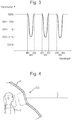
- a suitable transmission characteristic (which may alternatively be referred to as the transfer function) of visible electromagnetic radiation incident for the filter 10 is illustrated in Figure 3 .
- the transmission intensity relative to incident radiation intensity is shown on the y-axis and the wavelength of the incident radiation is shown on the x-axis.
- notches in the transmission characteristic associated with three wavelength bands are in particular a 10nm band centred on 455nm, a 10nm band centred on 532nm and a 10nm band centred on 650nm.
- any three notches from the group consisting of 405 nm, 455 nm, 520 nm, 532 nm, and 650 nm may be selected.
- notches may be chosen to coincide with any expected laser threat wavelength.
- the bandwidth may be 5 nm.
- the intensity of the transmitted radiation is at a minimum and has an optical density of approximately 3, which is equivalent to 0.1% of the initially incident radiation.
- Figure 4 shows a window 200 as shown in Figure 2 deployed as a windscreen on a vehicle V, which in this example is an aircraft.
- a pilot P is positioned behind the windscreen and a laser beam L, having a wavelength of 532 nm, is shown pointing at the windscreen.
- Laser beam L will have some degree of divergence as the beam propagates through the atmosphere, which will result in a certain 'spot size' observed at the windscreen.
- the window 200 may be used to mitigate the effects of the laser beam L, and alert the pilot to the existence of the laser threat.
- the laser beam L propagates onto the window 200 it will pass through the substrate 20 and into the detector layer 30 where some laser light will fall on one or more of the photodetectors 32 (depending on spot size).
- the laser light subsequently propagates from the detector layer 30 and on the filter 10 where the light becomes substantially attenuated.
- the filter 10 Assuming the filter 10 to have the transmission characteristics shown in Figure 3 and the laser beam L to be a green laser at 532 nm, the laser beam L will be attenuated to 0.1% of its original intensity.
- the pilot P is able to look out of the windscreen with a reduced chance of the laser beam L harming his or her sight, or distracting him or her from flying the plane safely.
- an electrical signal is generated at each illuminated detector 32 and sent to the processing unit 34.
- the electrical signals received from the illuminated photodetectors 32 are analysed to confirm or deny the detection of a laser beam.
- the processing module 36 generates a signal confirming the presence of the laser beam and relays this to the alert module 36.
- Each photodetector 32 can have a unique location at the filter, registered with the processor module such that signals from each photodetector 32 can be correlated with a certain location at the filter. Further this location can be correlated with a particular point on the window provided the relationship between the window and the filter is registered at the processing module.
- the processing module can determine, from detecting which photodetectors are illuminated, not only the presence of a threat but also the general dimensions of the 'spot' and where on the window the illumination is occurring. Some information relating to the source of the threat can be derived from such measurements. If embodiments are provided with layers of photodetectors, it may be possible to establish more confident estimates of the threat location.
- the photodetectors 32 are configured for detecting radiation at the predetermined wavelength or predetermined wavelengths.
- the photodetector 32 could be configured to send a signal only if 527- 537 nm radiation illuminated it. As such the system needs less noise-rejection provisions and/or can provide fewer false positive signals.
- the alert module Upon receiving the signal confirming the presence of the laser beam, the alert module issues an alert to notify the pilot P (or another operator) of the laser beam.
- alert could be a visual alert (for instance on an instrument in the cockpit) and/or an audible alert.
- Such alert could be a signal sent (e.g. by an RF transmitter within the alert module) to a further aircraft or a further element of aerospace infrastructure such as an Air Traffic Control base.
- the alert will inform as to the existence of the threat and further action (reporting to ground based security personnel, warning other aircraft) can be taken to address or remove the threat.
- Table 1 shows, for a 3 W laser with 0.5 mrad beam divergence and no atmospheric loss at various stand-off distances, the calculated minimum optical densities (OD) such that damage to the eye can be avoided by blinking (i.e. damage is negligible at this OD unless exposure is greater than 0.5 s, which is a determined minimum multiplied by a factor of safety of 2), and such that there is enough protection to render negligible the risk of damage from a 10 second exposure. Accordingly suggested ranges for ODs are proposed.
- Table 2 shows, for a 1 W laser with 1.2 mrad beam divergence and no atmospheric loss at various stand-off distances, the calculated minimum optical densities (OD) such that damage to the eye can be avoided by blinking (i.e. damage is negligible at this OD unless exposure is greater than 0.5 s, which is a determined minimum multiplied by a factor of safety of 2), and such that there is enough protection to render negligible the risk of damage from a 10 second exposure. Accordingly suggested ranges for ODs are proposed.
- the OD values given in Table 1 or Table 2 should be increased in each scenario by 1, or more preferably 1.5 (i.e. and OD of 1 should become and OD of 2 or 2.5 to prevent dazzle).
- the radiation detector may have the form of a patch arranged in the plane of the filter, or in other words at or near a boundary of the filter.
- Said patch could comprise an localised photodetector or array thereof and would be interfaced with the processor module and alert module in an equivalent manner. This approach would be suited to contexts where the spot size of the laser was sufficiently large to illuminate the periphery of the window, so that the patch need not be positioned in the operator's view.
- the detector could extend about the entire periphery of the filter.
- the filter 10 can be formed in any known way.
- the filter could be formed by a holographic process where a photosensitive substrate (e.g. polymeric film) is exposed by one or more lasers.
- a photosensitive substrate e.g. polymeric film
- the window may be comprised by a number of laminar substrates between which could be positioned the filter and detector of the present invention.
Landscapes
- Physics & Mathematics (AREA)
- General Physics & Mathematics (AREA)
- Engineering & Computer Science (AREA)
- Optics & Photonics (AREA)
- Mechanical Engineering (AREA)
- Structural Engineering (AREA)
- Civil Engineering (AREA)
- Spectroscopy & Molecular Physics (AREA)
- Chemical & Material Sciences (AREA)
- Crystallography & Structural Chemistry (AREA)
- Remote Sensing (AREA)
- Radar, Positioning & Navigation (AREA)
- Human Computer Interaction (AREA)
- Architecture (AREA)
- Computer Networks & Wireless Communication (AREA)
- Electromagnetism (AREA)
- Optical Radar Systems And Details Thereof (AREA)
- Optical Filters (AREA)
- Photometry And Measurement Of Optical Pulse Characteristics (AREA)
Description
- The present invention relates to a filter, and also to a window for a vehicle, the window comprising such a filter.
- It is known from
US2014/0293467 to provide a generally transparent filter comprising a nanoparticle metamaterial structure such that a particular wavelength of electromagnetic radiation may be blocked. The use of such a filter at the windscreen (or windshield) of an aircraft protects against laser threats, which may damage pilot eyesight or temporarily dazzle the pilot. DocumentWO 03/060443 A1 - According to the invention there is provided a passive filter for a vehicle window comprising a layer of filter material, the layer of filter material being for substantially preventing the transmission of radiation at a first predetermined visible wavelength band, the first predetermined visible wavelength band covering the wavelength of a predetermined laser threat, whilst substantially allowing visible wavelengths outside of the band to be transmitted, such that the filter can offer a visible light transmission of at least 70%, and a radiation detector arranged and configured in respect of said layer of filter material to detect radiation in the first predetermined wavelength band incident thereon and substantially blocked thereby.
- Thus, should the filter succeed in blocking laser dazzle, the existence of the threat can still be detected.
- The filter can optionally have a visible light transmission of at least 80% and may even be provided with a visible light transmission of 90%.
- The radiation detector may comprise a detector layer, the detector layer being mounted on the layer of filter material.
- Thus an integrated filter can be provided which is suitable for retrofit to existing windows.
- The radiation detector may comprise an array of photodetector elements.
- As such the detector has the option of collecting data relating to which photodetector elements have been illuminated and to what intensity. In such instances, the signals received from each photodetector element could be uniquely identifiable as originating from such element (e.g. by a unique connection to a unique port on a processor module).
- The radiation detector may comprise a photodetector element at a boundary of and generally co-planar with the layer of filter material.
- Thus the detector can be kept wholly out of the operator or operator's line of view and as such provides that larger or less inconspicuous photodetectors or sensing elements can be used.
- The filter may further comprise a processor module connected to the radiation detector, and a user alert module connected so the processor module such that an alert may be issued in the event of a detected laser threat.
- As such, should a laser threat be so effectively suppressed, there can still be identification and notification of the threat.
- The filter may comprise an interference filter configured to inhibit transmission at the or each predetermined wavelength band and formed by holographic exposure of a photosensitive film or films by one or more lasers.
- Such forms of filter can provide for the suppression of multiple narrow band wavelengths in the same material.
- The filter may be additionally for preventing transmission of radiation in a second predetermined wavelength band, the second predetermined wavelength band covering the wavelength of a second predetermined laser threat.
- The filter may be for additionally preventing radiation in a third predetermined visible radiation band, the third predetermined wavelength band covering the wavelength of a third predetermined laser threat.
- The filter may be for preventing radiation from no more than three predetermined radiation bands.
- As such more than one laser wavelength can be defended against.
- The filter may be comprised by a single layer of material adapted or configured for preventing the transmission of the predetermined visible wavelength band or bands.
- Typically the bandwidth of at least one of the predetermined bands is 10nm, but it may alternatively be 5nm.
- The filter may have an optical density of at least 2 at the first predetermined wavelength band. Where a plurality of predetermined wavelength bands are filtered by the filter, the optical density at each filter may be different according to the relative threat of that wavelength.
- The filter may have an optical density of at least 2 at each predetermined wavelength band.
- Such an optical density has been determined experimentally to be a suitable level of protection to defend against attacks from high power lasers (c. 3W) in aerospace contexts.
- The filter may be provided as a conformal film for coupling to a window to further adapt the filter for convenient retrofit.
- According to a further aspect of the invention, there is provided a multi-layered window comprising a filter according to the first aspect, wherein the filter is interposed between layers of the window.
- According to a still further aspect of the invention, there is provided a window for a vehicle, the window comprising a filter according to the first or further aspect of the invention.
- So that the invention may be well understood, exemplary embodiments thereof shall now be discussed with reference to the following figures, of which
-
Figure 1 shows a three-dimensional view of a known filter material applied to a substrate; -
Figure 2 shows a three-dimensional view of a filter according to the present invention; -
Figure 3 shows a graph where the generalised transmission characteristic of a filter material suitable for use in the filter is plotted, and -
Figure 4 shows the filter offigure 2 implemented on the windscreen of a vehicle. - With reference to
Figure 1 there is shown aprior art filter 10 applied to a first face of asubstrate 20 to provide awindow 100 adapted for mitigating laser threats such as dazzle. Thefilter 10 may be formed from metamaterials according to known practice. Thesubstrate 20 is substantially transmissive of visible light (for example it may have a visible light transmission (VLT%) of around 90% of normally incident light) and may be formed for example from a glass or a plastics material such as polycarbonate. - With reference to
Figure 2 there is shown generally at 200 a window. Thewindow 200 comprises atransparent substrate 20 to a first face of which has been coupled a radiation detector in the form of a detector layer 30. - Coupled to the opposite face of the detector layer 30 there is provided a layer of
filter material 10. - As such the
substrate 20, detector layer 30 andfilter material 10 can be considered as a stacked multi-layer structure. - The detector layer 30 comprises an array of
photodetectors 32 distributed so as to extend substantially across thewindow 200. Thephotodetectors 32 are sufficiently small to be substantially invisible to the casual observer (though in practice there may be some reduction on the VLT%). Each photodetector is electrically connected to aprocessor module 34. In some embodiments, including the present one, each photodetector is uniquely connected to a unique port on theprocessor module 34. - The
processor module 34 is in turn connected to analert module 36. - A suitable transmission characteristic (which may alternatively be referred to as the transfer function) of visible electromagnetic radiation incident for the
filter 10 is illustrated inFigure 3 . The transmission intensity relative to incident radiation intensity is shown on the y-axis and the wavelength of the incident radiation is shown on the x-axis. - As can be seen on the plot, across the range of wavelengths the intensity of the transmitted radiation is close to 100% of that which is incident.
- However there are three distinct notches in the transmission characteristic associated with three wavelength bands. These are in particular a 10nm band centred on 455nm, a 10nm band centred on 532nm and a 10nm band centred on 650nm. In general any three notches from the group consisting of 405 nm, 455 nm, 520 nm, 532 nm, and 650 nm may be selected. Further, notches may be chosen to coincide with any expected laser threat wavelength. Still further, the bandwidth may be 5 nm.
- At the centre of each of these bands, the intensity of the transmitted radiation is at a minimum and has an optical density of approximately 3, which is equivalent to 0.1% of the initially incident radiation.
-
Figure 4 shows awindow 200 as shown inFigure 2 deployed as a windscreen on a vehicle V, which in this example is an aircraft. A pilot P is positioned behind the windscreen and a laser beam L, having a wavelength of 532 nm, is shown pointing at the windscreen. Laser beam L will have some degree of divergence as the beam propagates through the atmosphere, which will result in a certain 'spot size' observed at the windscreen. - In use the
window 200 may be used to mitigate the effects of the laser beam L, and alert the pilot to the existence of the laser threat. - In particular, as the laser beam L propagates onto the
window 200 it will pass through thesubstrate 20 and into the detector layer 30 where some laser light will fall on one or more of the photodetectors 32 (depending on spot size). - The laser light subsequently propagates from the detector layer 30 and on the
filter 10 where the light becomes substantially attenuated. Assuming thefilter 10 to have the transmission characteristics shown inFigure 3 and the laser beam L to be a green laser at 532 nm, the laser beam L will be attenuated to 0.1% of its original intensity. - Accordingly, the pilot P is able to look out of the windscreen with a reduced chance of the laser beam L harming his or her sight, or distracting him or her from flying the plane safely.
- Meanwhile, the laser light having fallen on
certain photodetectors 32, an electrical signal is generated at eachilluminated detector 32 and sent to theprocessing unit 34. At theprocessing unit 34 the electrical signals received from the illuminatedphotodetectors 32 are analysed to confirm or deny the detection of a laser beam. In this case, theprocessing module 36 generates a signal confirming the presence of the laser beam and relays this to thealert module 36. - Each
photodetector 32 can have a unique location at the filter, registered with the processor module such that signals from eachphotodetector 32 can be correlated with a certain location at the filter. Further this location can be correlated with a particular point on the window provided the relationship between the window and the filter is registered at the processing module. Thus the processing module can determine, from detecting which photodetectors are illuminated, not only the presence of a threat but also the general dimensions of the 'spot' and where on the window the illumination is occurring. Some information relating to the source of the threat can be derived from such measurements. If embodiments are provided with layers of photodetectors, it may be possible to establish more confident estimates of the threat location. - In the present embodiment the
photodetectors 32 are configured for detecting radiation at the predetermined wavelength or predetermined wavelengths. For example thephotodetector 32 could be configured to send a signal only if 527- 537 nm radiation illuminated it. As such the system needs less noise-rejection provisions and/or can provide fewer false positive signals. - Upon receiving the signal confirming the presence of the laser beam, the alert module issues an alert to notify the pilot P (or another operator) of the laser beam. Such alert could be a visual alert (for instance on an instrument in the cockpit) and/or an audible alert. Such alert could be a signal sent (e.g. by an RF transmitter within the alert module) to a further aircraft or a further element of aerospace infrastructure such as an Air Traffic Control base.
- Accordingly, should the pilot be otherwise unaware of the laser beam (for instance because it is sufficiently attenuated by the
filter 10 to be negligible within the vehicle) the alert will inform as to the existence of the threat and further action (reporting to ground based security personnel, warning other aircraft) can be taken to address or remove the threat. - The above discussion has provided an overview of how the present invention may mitigate the threat of laser beams.
- Presently various lasers are commercially available which could be used against a number of targets at a number of different stand-off ranges. The likely distance and the power of the laser determine how effective the filter needs to be in order to prevent injury to the onlooker. An intensity-at-eyeball of 0.001 W/cm2 or less should be sufficient to prevent eye damage.
- Table 1 shows, for a 3 W laser with 0.5 mrad beam divergence and no atmospheric loss at various stand-off distances, the calculated minimum optical densities (OD) such that damage to the eye can be avoided by blinking (i.e. damage is negligible at this OD unless exposure is greater than 0.5 s, which is a determined minimum multiplied by a factor of safety of 2), and such that there is enough protection to render negligible the risk of damage from a 10 second exposure. Accordingly suggested ranges for ODs are proposed.
Table 1 Distance (m) Beam diameter (mm) 'Spot' Size (mm2) Intensity (W/Cm2) Typical application min OD for 0.5s exposure min OD for 10s exposure Example OD ranges (to nearest 0.5) 0 3 7.1 42.4 n/a 4.03 4.63 4.5-6.0 5 6 23.8 12.6 Car/train/bus 3.50 4.10 3.5-5.5 10 8 50.3 6.0 Car/train/bus 3.18 3.78 3.5-5.5 50 28 615.8 0.5 Car/train/bus/aircraft 2.10 2.70 2.5-4.0 100 53 2206.2 0.1 Car/train/bus/aircraft 1.40 2.00 1.5-3.5 500 253 50272.6 0.006 Aircraft 0.18 0.78 0.5-2.5 1000 503 198712.8 0.002 Aircraft n/a 0.30 0-1.5 - Table 2 shows, for a 1 W laser with 1.2 mrad beam divergence and no atmospheric loss at various stand-off distances, the calculated minimum optical densities (OD) such that damage to the eye can be avoided by blinking (i.e. damage is negligible at this OD unless exposure is greater than 0.5 s, which is a determined minimum multiplied by a factor of safety of 2), and such that there is enough protection to render negligible the risk of damage from a 10 second exposure. Accordingly suggested ranges for ODs are proposed.
Table 2 Distance (m) Beam diameter (mm) 'Spot' size (mm2) Intensity (W/Cm2) Typical application min OD for 0.5s exposure min OD for 10s exposure Example OD ranges (to nearest 0.5) 0 3 7.1 14.1 n/a 3.55 4.15 4.0-5.5 5 9 63.6 1.57 Car/train/bus 2.59 3.20 3.0-4.5 10 15 176.7 0.57 Car/train/bus 2.15 2.76 2.5-4.5 50 63 3117.3 0.03 Car/train/bus/aircraft 0.88 1.48 1.0-3.0 100 123 11882.3 0.008 Car/train/bus/aircraft 0.30 0.90 0.5-2.5 500 603 285577.8 0.0004 Aircraft n/a n/a 0.5-1.5 1000 1203 1136635.3 0.00009 Aircraft n/a n/a n/a - These experiments show that an optical density of 2 would tend to provide sufficient attenuation for aerospace applications, where attackers would struggle to get within 100 m of the aircraft.
- So that the dazzle can be prevented (dazzle being where the vision of the operator is temporarily impaired by the laser light but not permanently damaged) the OD values given in Table 1 or Table 2 should be increased in each scenario by 1, or more preferably 1.5 (i.e. and OD of 1 should become and OD of 2 or 2.5 to prevent dazzle).
- In a variant of the radiation detector shown in
Figure 2 , the radiation detector may have the form of a patch arranged in the plane of the filter, or in other words at or near a boundary of the filter. Said patch could comprise an localised photodetector or array thereof and would be interfaced with the processor module and alert module in an equivalent manner. This approach would be suited to contexts where the spot size of the laser was sufficiently large to illuminate the periphery of the window, so that the patch need not be positioned in the operator's view. As an alternative to the patch, the detector could extend about the entire periphery of the filter. - The
filter 10 can be formed in any known way. Alternatively the filter could be formed by a holographic process where a photosensitive substrate (e.g. polymeric film) is exposed by one or more lasers. - In a variant of the window and substrate arrangement of
Figure 2 , the window may be comprised by a number of laminar substrates between which could be positioned the filter and detector of the present invention.
Claims (15)
- A passive filter (200) for a vehicle window comprising A layer (10) of filter material,
the layer of filter material being for substantially preventing the transmission of radiation at a first predetermined visible wavelength band,
the first predetermined visible wavelength band covering the wavelength of a predetermined laser threat, whilst substantially allowing visible wavelengths outside of the band to be transmitted,
such that the filter can offer a visible light transmission of at least 70%,
and a radiation detector (30) arranged and configured in respect of said layer of filter material to detect radiation in the first predetermined wavelength band incident on, and substantially blocked by, the layer of filter material. - A passive filter according to claim 1 wherein the radiation detector comprises a detector layer, the detector layer being mounted on the layer of filter material.
- A passive filter according to claim 1 or 2 wherein the radiation detector comprises an array of photodetector elements.
- A passive filter according to any one of the preceding claims wherein the radiation detector comprises a photodetector element at a boundary of and generally co-planar with the layer of filter material.
- A passive filter according to any one of the preceding claims further comprising a processor module connected to the radiation detector, and a user alert module connected so the processor module such that an alert may be issued in the event of a detected laser threat.
- A passive filter according to any one of the preceding claims wherein the filter comprises an interference filter configured to inhibit transmission at the or each predetermined wavelength band and formed by holographic exposure of a photosensitive film or films by one or more lasers.
- A passive filter according to any of the preceding claims wherein the filter is additionally for preventing transmission of radiation in a second predetermined wavelength band, the second predetermined wavelength band covering the wavelength of a second predetermined laser threat.
- A passive filter according to any of the preceding claims wherein the filter is for additionally preventing radiation in a third predetermined visible radiation band, the third predetermined wavelength band covering the wavelength of a third predetermined laser threat.
- A passive filter according to any of the preceding claims wherein the filter is for preventing radiation from no more than three predetermined radiation bands.
- A passive filter according to any one of the preceding claims wherein the filter is comprised by a single layer of material adapted or configured for preventing the transmission of the predetermined visible wavelength band or bands.
- A passive filter according to any one of the preceding claims wherein the bandwidth of at least one of the predetermined bands is 10nm.
- A passive filter according to any one of the preceding claims wherein the filter has an optical density of at least 2 at each predetermined wavelength band.
- A passive filter according to any one of the preceding claims wherein the filter is provided as a conformal film for coupling to a window.
- A multi-layered window comprising a passive filter according to any one of claims 1 to 13, wherein the passive filter is interposed between layers of the window.
- A window for a vehicle, the window comprising a passive filter according to any one of claims 1 to 13.
Applications Claiming Priority (3)
| Application Number | Priority Date | Filing Date | Title |
|---|---|---|---|
| GBGB1604994.2A GB201604994D0 (en) | 2016-03-24 | 2016-03-24 | Filter |
| GB1619767.5A GB2548659B (en) | 2016-03-24 | 2016-11-23 | Filter |
| PCT/GB2017/050741 WO2017163028A1 (en) | 2016-03-24 | 2017-03-17 | Filter |
Publications (2)
| Publication Number | Publication Date |
|---|---|
| EP3433644A1 EP3433644A1 (en) | 2019-01-30 |
| EP3433644B1 true EP3433644B1 (en) | 2020-07-15 |
Family
ID=56027309
Family Applications (1)
| Application Number | Title | Priority Date | Filing Date |
|---|---|---|---|
| EP17713393.1A Active EP3433644B1 (en) | 2016-03-24 | 2017-03-17 | Filter |
Country Status (4)
| Country | Link |
|---|---|
| US (1) | US10815720B2 (en) |
| EP (1) | EP3433644B1 (en) |
| GB (3) | GB201604994D0 (en) |
| WO (2) | WO2017163028A1 (en) |
Families Citing this family (2)
| Publication number | Priority date | Publication date | Assignee | Title |
|---|---|---|---|---|
| GB201604994D0 (en) | 2016-03-24 | 2016-05-11 | Bae Systems Plc | Filter |
| GB201604995D0 (en) | 2016-03-24 | 2016-05-11 | Bae Systems Plc | Filter |
Family Cites Families (34)
| Publication number | Priority date | Publication date | Assignee | Title |
|---|---|---|---|---|
| US4637678A (en) | 1982-06-01 | 1987-01-20 | Hughes Aircraft Company | Holographic laser protection device |
| US4786125A (en) | 1983-08-22 | 1988-11-22 | Farrand Optical Co. | Ocular protective apparatus |
| US4879167A (en) * | 1987-08-25 | 1989-11-07 | Kaiser Optical System, Inc. | Real time holographic filter using nonlinear optical materials |
| US6785032B1 (en) * | 1988-07-28 | 2004-08-31 | Recon/Optical, Inc. | Laser countermeasure system and method |
| US4963471A (en) | 1989-07-14 | 1990-10-16 | E. I. Du Pont De Nemours And Company | Holographic photopolymer compositions and elements for refractive index imaging |
| US6411451B1 (en) | 1990-03-28 | 2002-06-25 | The United States Of America As Represented By The Secretary Of The Navy | Laser protection system |
| US5103323A (en) | 1990-04-18 | 1992-04-07 | Holographic Optics, Inc. | Multi-layer holographic notch filter |
| JPH055804A (en) | 1991-06-28 | 1993-01-14 | Fujitsu Ltd | Protective filter for laser |
| FR2687484A1 (en) | 1992-02-18 | 1993-08-20 | Sextant Avionique | HOLOGRAPHIC FILTER FOR PROTECTION AGAINST RADIATION, IN PARTICULAR LASER. |
| US5412439A (en) * | 1993-02-17 | 1995-05-02 | Northrop Grumman Corporation | Laser visor having overlying photosensors |
| US5966240A (en) | 1997-11-21 | 1999-10-12 | Coherent, Inc. | Laser blocking filter with neutral transmission color |
| EP1495292A4 (en) * | 2001-12-21 | 2012-05-09 | Malvern Instr Inc | Spectrometric process monitoring |
| US7202852B2 (en) * | 2004-01-23 | 2007-04-10 | Harvie Mark R | Active laser protection system |
| WO2006073408A2 (en) * | 2005-01-07 | 2006-07-13 | Harvie Mark R | Active laser protection system |
| US8882267B2 (en) | 2006-03-20 | 2014-11-11 | High Performance Optics, Inc. | High energy visible light filter systems with yellowness index values |
| WO2008074057A1 (en) | 2006-12-19 | 2008-06-26 | Ellex Medical Pty Ltd | Beam blocking and combining optic |
| US7630128B2 (en) * | 2007-02-02 | 2009-12-08 | Sperian Eye & Face Protection Inc. a Delaware Corporation | Optical filter panel having a narrow-width selective-wavelength attenuation and high visible light transmission |
| US7688524B2 (en) | 2008-04-24 | 2010-03-30 | Sperian Eye & Face Protection, Inc. | Laser protective eyewear having improved glare protection |
| US7683310B1 (en) * | 2008-04-24 | 2010-03-23 | Sandia Corporation | Laser warning receiver to identify the wavelength and angle of arrival of incident laser light |
| CN101758227B (en) | 2008-09-30 | 2011-10-26 | 王惠民 | Nanometer iron powder special for shielding electromagnetic wave and radar wave in glass cockpit of airplane |
| US8023195B2 (en) * | 2008-10-23 | 2011-09-20 | Gentex Corporation | Split laser eye protection system |
| US20100149483A1 (en) | 2008-12-12 | 2010-06-17 | Chiavetta Iii Stephen V | Optical Filter for Selectively Blocking Light |
| DE102011005136B4 (en) | 2011-03-04 | 2012-10-04 | Infitec Gmbh | Spectacles for viewing stereoscopic images or a perspective partial image of such |
| GB201117480D0 (en) * | 2011-10-10 | 2011-11-23 | Palikaras George | Filter |
| EP2602655B1 (en) | 2011-12-08 | 2024-04-03 | Essilor International | Ophthalmic filter |
| US20130215499A1 (en) | 2012-02-21 | 2013-08-22 | Semrock, Inc. | Notch filter system using spectral inversion |
| DE102013002385A1 (en) * | 2013-02-13 | 2014-08-14 | Antonia Scher | Window for a motor vehicle, in particular aircraft |
| IL226996A (en) * | 2013-06-17 | 2015-05-31 | Elbit Systems Land & C4I Ltd | Threat warning system integrating flash event and transmitted laser detection |
| US9970811B2 (en) * | 2013-08-30 | 2018-05-15 | Torrey Pines Logic, Inc. | Passive, wide-spectral-band laser threat sensor |
| US9739916B2 (en) | 2014-03-20 | 2017-08-22 | 3M Innovative Properties Company | Circadian rhythm optical film |
| US9958583B1 (en) | 2014-05-15 | 2018-05-01 | Rockwell Collins, Inc. | Green laser line notch absorber |
| US9645414B2 (en) * | 2014-05-22 | 2017-05-09 | Perriquest Defense Research Enterprises, Llc | Laser protection eyewear |
| GB201604995D0 (en) | 2016-03-24 | 2016-05-11 | Bae Systems Plc | Filter |
| GB201604994D0 (en) | 2016-03-24 | 2016-05-11 | Bae Systems Plc | Filter |
-
2016
- 2016-03-24 GB GBGB1604994.2A patent/GB201604994D0/en not_active Ceased
- 2016-11-23 GB GB1619804.6A patent/GB2548661A/en not_active Withdrawn
- 2016-11-23 GB GB1619767.5A patent/GB2548659B/en not_active Expired - Fee Related
-
2017
- 2017-03-17 WO PCT/GB2017/050741 patent/WO2017163028A1/en not_active Ceased
- 2017-03-17 US US16/087,116 patent/US10815720B2/en active Active
- 2017-03-17 EP EP17713393.1A patent/EP3433644B1/en active Active
- 2017-03-22 WO PCT/GB2017/050796 patent/WO2017163057A1/en not_active Ceased
Non-Patent Citations (1)
| Title |
|---|
| None * |
Also Published As
| Publication number | Publication date |
|---|---|
| GB201604994D0 (en) | 2016-05-11 |
| EP3433644A1 (en) | 2019-01-30 |
| WO2017163057A1 (en) | 2017-09-28 |
| US20190093420A1 (en) | 2019-03-28 |
| GB2548661A (en) | 2017-09-27 |
| WO2017163028A1 (en) | 2017-09-28 |
| GB2548659A (en) | 2017-09-27 |
| GB201619804D0 (en) | 2017-01-04 |
| GB2548659B (en) | 2020-04-29 |
| US10815720B2 (en) | 2020-10-27 |
| GB201619767D0 (en) | 2017-01-04 |
Similar Documents
| Publication | Publication Date | Title |
|---|---|---|
| US10845517B2 (en) | Filter for laser protection | |
| US7095026B2 (en) | Methods and apparatuses for selectively limiting undesired radiation | |
| US9674413B1 (en) | Vision system and method having improved performance and solar mitigation | |
| US20120037803A1 (en) | Electromagnetic interference shield | |
| EP2752681B1 (en) | Laser detection and warning system | |
| WO2012096702A2 (en) | Laser protection structures and methods of fabrication | |
| US9574741B2 (en) | Laser protective device with reflecting filter on non-absorbing and absorbing substrates | |
| US10815720B2 (en) | Passive filter for laser protection | |
| US20090020703A1 (en) | Optical filter for improved white light immunity in an intrusion detector | |
| US20100001894A1 (en) | Millimeter wave filters | |
| GB2548658A (en) | Filters for laser protection | |
| US5005926A (en) | Ballistic protective laser shield | |
| US9958583B1 (en) | Green laser line notch absorber | |
| US10006745B2 (en) | Detection system | |
| US20150138614A1 (en) | Windshield image display system | |
| US9788399B1 (en) | System and method for flight deck laser flash mitigation | |
| US20230280514A1 (en) | Retroreflection defeat filter | |
| US11556019B1 (en) | Viewing protection system for laser threats against aircraft | |
| JP2019070537A (en) | Color sensor and laser system including color sensor | |
| US20200370366A1 (en) | Security providing windows | |
| DeLauter | Assessing Potential Laser Strike Protection Engineering Control for United States Coast Guard Aircraft | |
| DeLauter | Mike Yost, PhD, MS Marty Cohen, ScD, CIH, CSP June Spector, MD, MPH | |
| KR20210065665A (en) | Short Wave Infrared Camera Optical System | |
| GB2123950A (en) | Intruder detection system |
Legal Events
| Date | Code | Title | Description |
|---|---|---|---|
| STAA | Information on the status of an ep patent application or granted ep patent |
Free format text: STATUS: UNKNOWN |
|
| STAA | Information on the status of an ep patent application or granted ep patent |
Free format text: STATUS: THE INTERNATIONAL PUBLICATION HAS BEEN MADE |
|
| PUAI | Public reference made under article 153(3) epc to a published international application that has entered the european phase |
Free format text: ORIGINAL CODE: 0009012 |
|
| STAA | Information on the status of an ep patent application or granted ep patent |
Free format text: STATUS: REQUEST FOR EXAMINATION WAS MADE |
|
| 17P | Request for examination filed |
Effective date: 20181004 |
|
| AK | Designated contracting states |
Kind code of ref document: A1 Designated state(s): AL AT BE BG CH CY CZ DE DK EE ES FI FR GB GR HR HU IE IS IT LI LT LU LV MC MK MT NL NO PL PT RO RS SE SI SK SM TR |
|
| AX | Request for extension of the european patent |
Extension state: BA ME |
|
| DAV | Request for validation of the european patent (deleted) | ||
| DAX | Request for extension of the european patent (deleted) | ||
| GRAP | Despatch of communication of intention to grant a patent |
Free format text: ORIGINAL CODE: EPIDOSNIGR1 |
|
| STAA | Information on the status of an ep patent application or granted ep patent |
Free format text: STATUS: GRANT OF PATENT IS INTENDED |
|
| INTG | Intention to grant announced |
Effective date: 20200228 |
|
| GRAS | Grant fee paid |
Free format text: ORIGINAL CODE: EPIDOSNIGR3 |
|
| GRAA | (expected) grant |
Free format text: ORIGINAL CODE: 0009210 |
|
| STAA | Information on the status of an ep patent application or granted ep patent |
Free format text: STATUS: THE PATENT HAS BEEN GRANTED |
|
| AK | Designated contracting states |
Kind code of ref document: B1 Designated state(s): AL AT BE BG CH CY CZ DE DK EE ES FI FR GB GR HR HU IE IS IT LI LT LU LV MC MK MT NL NO PL PT RO RS SE SI SK SM TR |
|
| REG | Reference to a national code |
Ref country code: CH Ref legal event code: EP Ref country code: GB Ref legal event code: FG4D |
|
| REG | Reference to a national code |
Ref country code: IE Ref legal event code: FG4D |
|
| REG | Reference to a national code |
Ref country code: DE Ref legal event code: R096 Ref document number: 602017019786 Country of ref document: DE |
|
| REG | Reference to a national code |
Ref country code: AT Ref legal event code: REF Ref document number: 1291646 Country of ref document: AT Kind code of ref document: T Effective date: 20200815 |
|
| REG | Reference to a national code |
Ref country code: SE Ref legal event code: TRGR |
|
| REG | Reference to a national code |
Ref country code: LT Ref legal event code: MG4D |
|
| REG | Reference to a national code |
Ref country code: AT Ref legal event code: MK05 Ref document number: 1291646 Country of ref document: AT Kind code of ref document: T Effective date: 20200715 |
|
| REG | Reference to a national code |
Ref country code: NL Ref legal event code: MP Effective date: 20200715 |
|
| PG25 | Lapsed in a contracting state [announced via postgrant information from national office to epo] |
Ref country code: FI Free format text: LAPSE BECAUSE OF FAILURE TO SUBMIT A TRANSLATION OF THE DESCRIPTION OR TO PAY THE FEE WITHIN THE PRESCRIBED TIME-LIMIT Effective date: 20200715 Ref country code: AT Free format text: LAPSE BECAUSE OF FAILURE TO SUBMIT A TRANSLATION OF THE DESCRIPTION OR TO PAY THE FEE WITHIN THE PRESCRIBED TIME-LIMIT Effective date: 20200715 Ref country code: GR Free format text: LAPSE BECAUSE OF FAILURE TO SUBMIT A TRANSLATION OF THE DESCRIPTION OR TO PAY THE FEE WITHIN THE PRESCRIBED TIME-LIMIT Effective date: 20201016 Ref country code: HR Free format text: LAPSE BECAUSE OF FAILURE TO SUBMIT A TRANSLATION OF THE DESCRIPTION OR TO PAY THE FEE WITHIN THE PRESCRIBED TIME-LIMIT Effective date: 20200715 Ref country code: NO Free format text: LAPSE BECAUSE OF FAILURE TO SUBMIT A TRANSLATION OF THE DESCRIPTION OR TO PAY THE FEE WITHIN THE PRESCRIBED TIME-LIMIT Effective date: 20201015 Ref country code: ES Free format text: LAPSE BECAUSE OF FAILURE TO SUBMIT A TRANSLATION OF THE DESCRIPTION OR TO PAY THE FEE WITHIN THE PRESCRIBED TIME-LIMIT Effective date: 20200715 Ref country code: LT Free format text: LAPSE BECAUSE OF FAILURE TO SUBMIT A TRANSLATION OF THE DESCRIPTION OR TO PAY THE FEE WITHIN THE PRESCRIBED TIME-LIMIT Effective date: 20200715 Ref country code: BG Free format text: LAPSE BECAUSE OF FAILURE TO SUBMIT A TRANSLATION OF THE DESCRIPTION OR TO PAY THE FEE WITHIN THE PRESCRIBED TIME-LIMIT Effective date: 20201015 Ref country code: PT Free format text: LAPSE BECAUSE OF FAILURE TO SUBMIT A TRANSLATION OF THE DESCRIPTION OR TO PAY THE FEE WITHIN THE PRESCRIBED TIME-LIMIT Effective date: 20201116 |
|
| PG25 | Lapsed in a contracting state [announced via postgrant information from national office to epo] |
Ref country code: PL Free format text: LAPSE BECAUSE OF FAILURE TO SUBMIT A TRANSLATION OF THE DESCRIPTION OR TO PAY THE FEE WITHIN THE PRESCRIBED TIME-LIMIT Effective date: 20200715 Ref country code: LV Free format text: LAPSE BECAUSE OF FAILURE TO SUBMIT A TRANSLATION OF THE DESCRIPTION OR TO PAY THE FEE WITHIN THE PRESCRIBED TIME-LIMIT Effective date: 20200715 Ref country code: RS Free format text: LAPSE BECAUSE OF FAILURE TO SUBMIT A TRANSLATION OF THE DESCRIPTION OR TO PAY THE FEE WITHIN THE PRESCRIBED TIME-LIMIT Effective date: 20200715 Ref country code: IS Free format text: LAPSE BECAUSE OF FAILURE TO SUBMIT A TRANSLATION OF THE DESCRIPTION OR TO PAY THE FEE WITHIN THE PRESCRIBED TIME-LIMIT Effective date: 20201115 |
|
| PG25 | Lapsed in a contracting state [announced via postgrant information from national office to epo] |
Ref country code: NL Free format text: LAPSE BECAUSE OF FAILURE TO SUBMIT A TRANSLATION OF THE DESCRIPTION OR TO PAY THE FEE WITHIN THE PRESCRIBED TIME-LIMIT Effective date: 20200715 |
|
| REG | Reference to a national code |
Ref country code: DE Ref legal event code: R097 Ref document number: 602017019786 Country of ref document: DE |
|
| PG25 | Lapsed in a contracting state [announced via postgrant information from national office to epo] |
Ref country code: IT Free format text: LAPSE BECAUSE OF FAILURE TO SUBMIT A TRANSLATION OF THE DESCRIPTION OR TO PAY THE FEE WITHIN THE PRESCRIBED TIME-LIMIT Effective date: 20200715 Ref country code: SM Free format text: LAPSE BECAUSE OF FAILURE TO SUBMIT A TRANSLATION OF THE DESCRIPTION OR TO PAY THE FEE WITHIN THE PRESCRIBED TIME-LIMIT Effective date: 20200715 Ref country code: EE Free format text: LAPSE BECAUSE OF FAILURE TO SUBMIT A TRANSLATION OF THE DESCRIPTION OR TO PAY THE FEE WITHIN THE PRESCRIBED TIME-LIMIT Effective date: 20200715 Ref country code: RO Free format text: LAPSE BECAUSE OF FAILURE TO SUBMIT A TRANSLATION OF THE DESCRIPTION OR TO PAY THE FEE WITHIN THE PRESCRIBED TIME-LIMIT Effective date: 20200715 Ref country code: CZ Free format text: LAPSE BECAUSE OF FAILURE TO SUBMIT A TRANSLATION OF THE DESCRIPTION OR TO PAY THE FEE WITHIN THE PRESCRIBED TIME-LIMIT Effective date: 20200715 Ref country code: DK Free format text: LAPSE BECAUSE OF FAILURE TO SUBMIT A TRANSLATION OF THE DESCRIPTION OR TO PAY THE FEE WITHIN THE PRESCRIBED TIME-LIMIT Effective date: 20200715 |
|
| PLBE | No opposition filed within time limit |
Free format text: ORIGINAL CODE: 0009261 |
|
| STAA | Information on the status of an ep patent application or granted ep patent |
Free format text: STATUS: NO OPPOSITION FILED WITHIN TIME LIMIT |
|
| PG25 | Lapsed in a contracting state [announced via postgrant information from national office to epo] |
Ref country code: AL Free format text: LAPSE BECAUSE OF FAILURE TO SUBMIT A TRANSLATION OF THE DESCRIPTION OR TO PAY THE FEE WITHIN THE PRESCRIBED TIME-LIMIT Effective date: 20200715 |
|
| 26N | No opposition filed |
Effective date: 20210416 |
|
| PG25 | Lapsed in a contracting state [announced via postgrant information from national office to epo] |
Ref country code: SK Free format text: LAPSE BECAUSE OF FAILURE TO SUBMIT A TRANSLATION OF THE DESCRIPTION OR TO PAY THE FEE WITHIN THE PRESCRIBED TIME-LIMIT Effective date: 20200715 |
|
| PG25 | Lapsed in a contracting state [announced via postgrant information from national office to epo] |
Ref country code: SI Free format text: LAPSE BECAUSE OF FAILURE TO SUBMIT A TRANSLATION OF THE DESCRIPTION OR TO PAY THE FEE WITHIN THE PRESCRIBED TIME-LIMIT Effective date: 20200715 |
|
| PG25 | Lapsed in a contracting state [announced via postgrant information from national office to epo] |
Ref country code: MC Free format text: LAPSE BECAUSE OF FAILURE TO SUBMIT A TRANSLATION OF THE DESCRIPTION OR TO PAY THE FEE WITHIN THE PRESCRIBED TIME-LIMIT Effective date: 20200715 |
|
| REG | Reference to a national code |
Ref country code: CH Ref legal event code: PL |
|
| REG | Reference to a national code |
Ref country code: BE Ref legal event code: MM Effective date: 20210331 |
|
| PG25 | Lapsed in a contracting state [announced via postgrant information from national office to epo] |
Ref country code: IE Free format text: LAPSE BECAUSE OF NON-PAYMENT OF DUE FEES Effective date: 20210317 Ref country code: CH Free format text: LAPSE BECAUSE OF NON-PAYMENT OF DUE FEES Effective date: 20210331 Ref country code: LI Free format text: LAPSE BECAUSE OF NON-PAYMENT OF DUE FEES Effective date: 20210331 Ref country code: LU Free format text: LAPSE BECAUSE OF NON-PAYMENT OF DUE FEES Effective date: 20210317 |
|
| PG25 | Lapsed in a contracting state [announced via postgrant information from national office to epo] |
Ref country code: BE Free format text: LAPSE BECAUSE OF NON-PAYMENT OF DUE FEES Effective date: 20210331 |
|
| PG25 | Lapsed in a contracting state [announced via postgrant information from national office to epo] |
Ref country code: CY Free format text: LAPSE BECAUSE OF FAILURE TO SUBMIT A TRANSLATION OF THE DESCRIPTION OR TO PAY THE FEE WITHIN THE PRESCRIBED TIME-LIMIT Effective date: 20200715 |
|
| PG25 | Lapsed in a contracting state [announced via postgrant information from national office to epo] |
Ref country code: HU Free format text: LAPSE BECAUSE OF FAILURE TO SUBMIT A TRANSLATION OF THE DESCRIPTION OR TO PAY THE FEE WITHIN THE PRESCRIBED TIME-LIMIT; INVALID AB INITIO Effective date: 20170317 |
|
| PG25 | Lapsed in a contracting state [announced via postgrant information from national office to epo] |
Ref country code: MK Free format text: LAPSE BECAUSE OF FAILURE TO SUBMIT A TRANSLATION OF THE DESCRIPTION OR TO PAY THE FEE WITHIN THE PRESCRIBED TIME-LIMIT Effective date: 20200715 |
|
| PG25 | Lapsed in a contracting state [announced via postgrant information from national office to epo] |
Ref country code: TR Free format text: LAPSE BECAUSE OF FAILURE TO SUBMIT A TRANSLATION OF THE DESCRIPTION OR TO PAY THE FEE WITHIN THE PRESCRIBED TIME-LIMIT Effective date: 20200715 |
|
| PG25 | Lapsed in a contracting state [announced via postgrant information from national office to epo] |
Ref country code: MT Free format text: LAPSE BECAUSE OF FAILURE TO SUBMIT A TRANSLATION OF THE DESCRIPTION OR TO PAY THE FEE WITHIN THE PRESCRIBED TIME-LIMIT Effective date: 20200715 |
|
| PGFP | Annual fee paid to national office [announced via postgrant information from national office to epo] |
Ref country code: SE Payment date: 20260219 Year of fee payment: 10 |
|
| PGFP | Annual fee paid to national office [announced via postgrant information from national office to epo] |
Ref country code: GB Payment date: 20260219 Year of fee payment: 10 |
|
| PGFP | Annual fee paid to national office [announced via postgrant information from national office to epo] |
Ref country code: DE Payment date: 20260219 Year of fee payment: 10 |
|
| PGFP | Annual fee paid to national office [announced via postgrant information from national office to epo] |
Ref country code: FR Payment date: 20260219 Year of fee payment: 10 |