EP3432974B1 - System for suppressing vestibular activity of a human subject - Google Patents
System for suppressing vestibular activity of a human subject Download PDFInfo
- Publication number
- EP3432974B1 EP3432974B1 EP17770755.1A EP17770755A EP3432974B1 EP 3432974 B1 EP3432974 B1 EP 3432974B1 EP 17770755 A EP17770755 A EP 17770755A EP 3432974 B1 EP3432974 B1 EP 3432974B1
- Authority
- EP
- European Patent Office
- Prior art keywords
- human subject
- electrode
- electrical stimulation
- head
- electrodes
- Prior art date
- Legal status (The legal status is an assumption and is not a legal conclusion. Google has not performed a legal analysis and makes no representation as to the accuracy of the status listed.)
- Active
Links
Images


Classifications
-
- A—HUMAN NECESSITIES
- A61—MEDICAL OR VETERINARY SCIENCE; HYGIENE
- A61N—ELECTROTHERAPY; MAGNETOTHERAPY; RADIATION THERAPY; ULTRASOUND THERAPY
- A61N1/00—Electrotherapy; Circuits therefor
- A61N1/02—Details
- A61N1/04—Electrodes
- A61N1/0404—Electrodes for external use
- A61N1/0408—Use-related aspects
- A61N1/0456—Specially adapted for transcutaneous electrical nerve stimulation [TENS]
-
- A—HUMAN NECESSITIES
- A61—MEDICAL OR VETERINARY SCIENCE; HYGIENE
- A61N—ELECTROTHERAPY; MAGNETOTHERAPY; RADIATION THERAPY; ULTRASOUND THERAPY
- A61N1/00—Electrotherapy; Circuits therefor
- A61N1/18—Applying electric currents by contact electrodes
- A61N1/32—Applying electric currents by contact electrodes alternating or intermittent currents
- A61N1/36—Applying electric currents by contact electrodes alternating or intermittent currents for stimulation
- A61N1/36014—External stimulators, e.g. with patch electrodes
- A61N1/3603—Control systems
- A61N1/36034—Control systems specified by the stimulation parameters
-
- A—HUMAN NECESSITIES
- A61—MEDICAL OR VETERINARY SCIENCE; HYGIENE
- A61N—ELECTROTHERAPY; MAGNETOTHERAPY; RADIATION THERAPY; ULTRASOUND THERAPY
- A61N1/00—Electrotherapy; Circuits therefor
- A61N1/18—Applying electric currents by contact electrodes
- A61N1/32—Applying electric currents by contact electrodes alternating or intermittent currents
- A61N1/36—Applying electric currents by contact electrodes alternating or intermittent currents for stimulation
- A61N1/36036—Applying electric currents by contact electrodes alternating or intermittent currents for stimulation of the outer, middle or inner ear
-
- A—HUMAN NECESSITIES
- A61—MEDICAL OR VETERINARY SCIENCE; HYGIENE
- A61N—ELECTROTHERAPY; MAGNETOTHERAPY; RADIATION THERAPY; ULTRASOUND THERAPY
- A61N1/00—Electrotherapy; Circuits therefor
- A61N1/18—Applying electric currents by contact electrodes
- A61N1/20—Applying electric currents by contact electrodes continuous direct currents
Definitions
- This description relates to a system and method for suppressing vestibular activity of a human subject.
- the present invention relates to a system for suppressing vestibular activity as defined in claim 1.
- the ability to maintain spatial orientation and balance is the result of an elaborate synchronization of neural inputs from the vestibular, visual, and proprioceptive systems.
- spatial disorientation may occur.
- the two primary conflicts occur between the visual and vestibular senses (i.e., intersensory conflict) and within the vestibular sense between the semicircular canals and otoliths (i.e., intrasensory conflict).
- Secondary conflict may come from proprioceptive inputs that fail to synchronize with other sensory cues, particularly visual and peripheral proprioceptors connected to the vestibular system through vestibulospinal pathways.
- Motion Sickness This creates the sensation commonly known as Motion Sickness. It includes a range of symptoms, from nausea and salivation to a sensation of warmth, tiredness, and other cognitive symptoms.
- sensory conflicts remain one of the most persistent issues facing advanced flight simulation development. Flight simulators have been shown to improve training effectiveness with considerably lower cost and risk than actual flight training. The capability to use simulation in training brings advantages in acquisition of skill sets, development of competencies, the reduction of errors in real environments, and decreased costs.
- the simulation environment however, imposes limitations in matching real world sensory experiences. These limitations may manifest in the form of simulator-induced motion sickness, also known as simulator sickness (SS).
- SS is a variant of motion sickness resulting from exposure to simulated environments such as flight simulators, driving simulators and similar virtual, immersive environments.
- SS is mainly the result of technological limitations in simulating dynamic environments that create a conflict in the body's self-motion perception sensors. Because of the wide variety of these symptoms, such as nausea, oculomotor disorders, disorientation, and the like, SS has also been described as "polygenic" since several factors have been identified including age, gender, simulator features, e.g., lag and field of view (FOV), and factors associated with the task performed, e.g., duration and degree of control.
- age, gender simulator features, e.g., lag and field of view (FOV)
- FOV field of view
- the theory of sensory conflict also known as the sensory rearrangement or neural mismatch theory, indicates that sickness occurs when the pattern of inputs from different senses and within a single sensory modality do not correspond to the stored patterns of such inputs based on past experience, as a result of both cognitive and perceptual discrepancy.
- SS symptoms develop, the value of the training experience and data derived during the experience may be compromised and in the most extreme cases results in negative transfer-of-training.
- various training centers routinely ground pilots for 6 to 24 hours after simulator time.
- U.S. Patent Publ. No. 2014/0127666 teaches systems and techniques for stimulating motion to a human subject alleviating motion sickness and directional cueing related to the vestibular system with coupling of galvanic vestibular stimulation GVS which relies on voltage and current unequally at two different points on a subject's head to cause a change in a vestibular response.
- U.S. Patent Publ. No. 2015/0039057 teaches an implantable nerve stimulation device sensor system.
- the nerve stimulation system includes an electrode array with electrodes that are invasively, surgically implanted in the human subject.
- Japanese Application No. 2006288665 teaches and discloses utilizing direct electrical current and utilizes a fixed reference voltage.
- CN2062231 teaches and discloses a complex device with gears, pendulums, double pole, single throw power switch and a light source which utilizes the swing of the hull of a boat to change intensity and a resistance which changes magnitude and current.
- Korean Publ. No. KR20160007957 relies on a left and right movement input value provided by a virtual reality device which is larger than a reference value to indicate predetermined left and right abrupt rotational sense such that a pair of alternating current stimuluses may be applied.
- US 2008/275513 also discloses a stimulation system known from the prior art.
- a system for suppressing vestibular activity of a human subject includes an electronics module configured to generate one or more electrical stimulation signals.
- a plurality of electrodes each placed proximate a predetermined location on a head of a human subject is configured to deliver the one or more electrical stimulation signals to the predetermined location to suppress vestibular activity of the human subject.
- the plurality of electrodes may be bi-laterally placed on opposing sides of the head.
- the predetermined location may include a mastoid process, the ear, or a temporal bone of the human subject.
- the one or more electrical stimulation signals may include one or more direct current (DC) signals.
- the one or more stimulation signals may include one or more DC signals each with an imposed carrier wave.
- the one or more stimulation signals may include one or more alternating current (AC) signals.
- the one or more electrical stimulation signals may be configured to hyperpolarize and/or depolarized cells located at each predetermined location to create a desired induced perception of motion.
- the plurality of electrodes may be configured to deliver electrical stimulation to suppress the vestibular system of the human subject to actual motion such that perception of motion of the human subject is reduced.
- the suppression of the vestibular system of the human subject to actual motion may decrease motion sickness that may arise from motion sensed by the human subject.
- the plurality of electrodes may include a first pair of electrodes placed on one side of the head of the human subject at the predetermined location, another pair of electrodes placed on an opposite side of the head of the human subject at the predetermined location, and a ground electrode placed on the head or neck of the human subject.
- Each pair of electrodes may include an electrode configured as positive electrode and an electrode configured as a negative electrode.
- the one or more electrical stimulation signals may be configured as one or more DC signals applied to each positive and negative electrode such that the one or more DC signals are transmitted from the positive electrode located at high predetermined location on the head of the human subject to the negative electrode located at a low location on the head of the human subject to suppress vestibular activity.
- the high predetermined location may include a high location on a mastoid process of the human subject and the low location includes a low location on mastoid process of the human subject.
- the one or more electrical stimulation signals may be configured as one or more DC signals each imposed carrier wave applied in phase to each positive and negative electrode such that the one or more DC signals with the imposed carrier waves are transmitted from the positive electrode at a high predetermined location to the negative electrode at a low predetermined location to suppress vestibular activity.
- the one or more electrical stimulation signals may be configured as one or more DC signals each imposed carrier wave applied temporally offset to each positive and negative electrode such that the one or more DC signals with the imposed carrier waves are transmitted from the positive electrode at a high predetermined location on one side of the head to the negative electrode at a low predetermined location on an opposite side of the head to suppress vestibular activity.
- the high predetermined location may include a high location on mastoid process and the low predetermined location includes a low location on mastoid process of the human subject.
- the plurality of electrodes may include one electrode placed on one side of the head of the human subject at the predetermined location and another electrode is placed on an opposite side of the head of the human subject at the predetermined location.
- the one or more electrical stimulation signals may be configured as one or more AC signals applied to the electrode placed on one side of the head and the electrode placed on one the opposite side of the head such that the one or more AC signals are transmitted back and forth from one electrode at its maximum current at the predetermined location on one side of the head to the another electrode at its maximum negative current at the predetermined location on an opposite side of the head of the human subject to suppress vestibular activity.
- a method for suppressing vestibular activity of a human subject includes generating one or more electrical stimulation signals, and delivering the one or more electrical stimulation signals to a plurality of electrodes each placed proximate a predetermined location on a head of the human subject such that the one or more electrical stimulation signals suppress vestibular activity of the human subject.
- the method may include bilaterally placing the electrodes on opposing sides of the head of the human subject at the predetermined location.
- the one or more electrical stimulation signals may hyperpolarize and/or may depolarize cells located at each predetermined location to create a desired induced perception of motion.
- the method may include delivering electrical stimulation to suppress the vestibular system of the human subject to actual motion such that perception of motion of the human subject is reduced. The suppression of the vestibular system of the human subject to actual motion may decrease motion sickness that may arise from motion sensed by the human subject.
- the one or more electrical stimulation signals may include one or more direct current (DC) signals.
- the one or more stimulation signals may include one or more DC signals each with an imposed carrier wave.
- the one or more stimulation signals may include one or more alternating current (AC) signals.
- the one more electrical stimulation signals may include one or more DC signals transmitted from a positive electrode at a high predetermined location on one side of the head to the negative electrode at a low predetermined location on an opposite side of the head to suppress vestibular activity.
- the one more electrical stimulation signals may include one or more DC signals with the imposed carrier waves transmitted in phase from a positive electrode at a high predetermined location on one side of the head to the negative electrode at a low predetermined location on an opposite side of the head to suppress vestibular activity.
- the one more electrical stimulation signals may include one or more DC signals with the imposed carrier waves transmitted temporally offset from a positive electrode at a high predetermined location on one side of the head to the negative electrode at a low predetermined location on an opposite side of the head to suppress vestibular activity.
- the one more electrical stimulation signals may include one or more AC signals transmitted from an electrode on one side of the head at the determined location to an electrode on an opposite side of the head to suppress vestibular activity.
- the present invention is set out in the appended claims and pertains to a system for suppressing vestibular activity of a human subject.
- System 10 includes electronics module 12 configured to generate one or more stimulation signals which are applied to electrodes at predetermined locations of head 14 of the human subject to suppress vestibular activity as will be discussed in detail below.
- Fig. 2 shows examples of electronics module 12 which is capable of generating the one or more electrical stimulation signals, e.g. up to about 2.5 mA in a DC mode or an AC mode with a frequency between about 300 Hz and 12 kHz using frequency control 16 and amplitude control 18.
- Electronics module 12 also preferably includes display 20 which displays the current and/or voltage of the one or more stimulation signals.
- electronics module 12 may be operated with batteries, e.g., 6 AA batteries indicated at 22.
- Electronics module 12 also preferably includes electronics board 24 which is coupled to frequency control 16, amplitude 18, display 20, and connectors 52.
- Electronics board 24 is configured to generate the one or more electrical stimulation signals.
- Figs. 3 and 4 show in further detail examples of electronic circuitry 25, 27, respectively, incorporated into electronics board 24 of electronics module 12, Figs. 1 and 2 , which may be used to generate the one or more electrical stimulation signals to suppress vestibular activity.
- System 10, Fig. 1 also includes a plurality of electrodes each placed proximate a predetermined location on head 14 of the human subject configured to deliver the one or more electrical stimulation signals to the predetermined location on head 14 to suppress vestibular activity.
- system 10 includes plurality of electrodes 22 placed proximate a predetermined on one side of head 14 and plurality of electrodes 26 bilaterally placed proximate a predetermined location on an opposite sided of head 14 as shown, e.g., proximate the mastoid process 40, Fig. 5 , and preferably within the area indicated at 42 which is located directly behind the external ear as shown.
- the predetermined location on each side of head 14 may the temporal bone, indicated at 46
- Fig. 6 shows exemplary electrodes which may be utilized (available from MFI Medical Equipment San Diego, CA) which are preferably coupled to connectors 52, Fig. 2 .
- one of the electrodes of the plurality of electrodes 22, Fig. 1 may be configured as a positive electrode by connecting it to contact 54 which outputs positive DC or AC current generated by electronics module 12.
- the other of plurality of electrodes 22, Fig. 1 e.g. electrode 54, may be configured as a negative electrode by connecting it to contact 58 which outputs negative DC or AC current generated by electronics module 12.
- one of the electrodes of the plurality of electrodes 26, e.g., electrode 60 may be configured as a positive electrode by connecting it to contact 62 which outputs positive DC or AC current or voltage generated by electronics module 12 and the other of the plurality of electrodes 22, e.g., electrode 66, may be configured as a negative electrode by connecting it to negative contact 68 which outputs negative DC or AC current or voltage generated by electronics module 12.
- system 10 includes ground electrode 70 preferably placed proximate the nape of the neck as shown coupled to ground contact 72.
- the one or more electrical stimulation signals generated by electronics module 12 to electrodes 50, 54 on one side of head 14 at the predetermined location and the one or more electrical stimulation signals applied to electrodes 60 and 66 at the predetermined location on an opposite side of head 14 of the human subject suppresses vestibular activity.
- the vestibular system of the human subject is suppressed to actual motion by system 10 and the method thereof such that the perception of motion of the human subject is reduced.
- Suppression of the vestibular system of the human subject to actual motion preferably decreases motion sickness and/or SS that may arise from motion sensed by the human subject.
- system 10 and the method thereof may mitigate motion sickness and/or SS by reducing or eliminating the mismatch between sensory cues inputs expected by a human subject and improve simulation based training.
- the one or more electrical stimulation signals generated by electronics module 12 and delivered by electrodes 50, 54 and 60, 66 preferably hyperpolarize and/or depolarize cells proximate each predetermined location on head 14 as discussed above to create a desired induced perception of motion.
- System 10 and the method thereof mimics the polarization of the cells caused by motion with the application of small amounts of external electrical stimulation by the one or more electrical stimulation signals.
- the cells on each side of head 14 are preferably hyperpolarized and/or depolarized thereby using their natural response to create the desired signals.
- system 10 and the method thereof works with the healthy vestibular system of the human subject to create a transient signal associated with acceleration of the head.
- the cells Upon cessation of stimulation, the cells repolarize to their "at rest" condition within a few pulses, requiring less than a second to return to their pre-stimulation condition. See Fig. 7 .
- the one or more electrical stimulation signals stimulation signals generated by electronics module 12, Figs. 1-4 , to suppress vestibular activity may include one or more direct current (DC) signals, one or more DC signals with an imposed carrier waves or one or more alternating current (AC) signals.
- DC direct current
- AC alternating current
- electronics module 12, Fig. 8 may generate one or more electrical stimulation signals to suppress vestibular activity configured as positive DC signal 80 which is applied electrode 50 preferably located at an upper mastoid location of the head 14 as shown, e.g., at location 43, Fig. 5 of area 42.
- Electronics module 12 may also generate negative DC signal 82 which is applied to electrode 52 preferably located at a lower mastoid position on the head 14 as shown, e.g., at location 45 of area 42.
- the one or more electrical stimulation signals in this example are transmitted from the upper mastoid location of the left side of head 14 to lower mastoid position on head 14 as shown by arrow 87 to suppress vestibular activity.
- electronics module 12 may generate one or more electrical stimulation signals to suppress vestibular activity configured as positive DC signal 84 which is applied electrode 60 preferably located at an upper mastoid location of the head 14, as discussed above.
- Electronics module 12 may also generate negative DC signal 86 which is applied to electrode 66 located at a lower mastoid position on the head 14 as shown, e.g., as discussed above.
- the one or more electrical stimulation signals in this example are transmitted from the upper mastoid location of the head 14 to lower mastoid position on the head, as shown by arrow 89, to suppress vestibular activity.
- Electronics module 12, Fig. 9 may generate one or more electrical stimulation signals to suppress vestibular activity configured as DC signal 90 with imposed positive carrier wave 92 which is applied electrode 50 preferably located at an upper mastoid location of the head 14 as shown, similarly as discussed above.
- Imposed carrier wave 92 modulates the current applied to electrode 50 between 0 amps, indicated at 93, and the maximum positive current, indicated at 95.
- Electronics module 12 may also generate DC signal 90 with imposed negative carrier wave 94 which is applied to electrode 52 located at a lower mastoid position on the head 14 as shown, similar as discussed above.
- Imposed negative carrier wave 94 modulates the current applied to electrode 52 between 0 amps, indicated at 95, and the maximum negative current, indicated at 97.
- imposed carrier waves 92 and 94 are preferably in phase such that the one or more electrical stimulation signals are transmitted from electrode 50 to electrode 52, as shown by arrow 97, to suppress vestibular activity.
- electronics module 12, Fig 9 may generate one or more electrical stimulation signals to suppress vestibular activity configured as configured as DC signal 100 with imposed positive carrier wave 102 which is applied electrode 60 preferably located at an upper mastoid location of the head 14 as shown.
- Imposed positive carrier wave 102 preferably modulates the current applied to electrode 60 between 0 amps, indicated at 101, and the maximum positive current, indicated at 103.
- Electronics module 12, Fig 9 may also generate DC signal 100 with imposed negative carrier wave 104 which is applied to electrode 66 located at a lower mastoid position on the head 14 as shown, as discussed above.
- Imposed negative carrier wave 104 modulates the current applied to electrode 66 between 0 amps, indicated at 101, and the maximum negative current, indicated at 105.
- carrier waves 102 and 104 are preferably in phase such that the electrical stimulation signals are transmitted from electrode 60 to electrode 66 as shown by arrow 99, to suppress vestibular activity.
- electronics module 12, Fig. 10 may generate DC signal 90 with imposed carrier waves 92 and 94 which are preferably temporally offset, e.g., 180 degrees out phase, with DC signal 100 with carrier waves 102 and 104 as shown.
- the result is current is transmitted from electrode 50 at its maximum current on one side of head 14 at a higher mastoid position to electrode 66 at zero current on an opposite side of head 14 a lower mastoid position, as shown by arrow 110, and from electrode 60 at its maximum current on side of head 14 at a higher mastoid position to electrode 52 at zero current, on an opposite side of head 14 at a lower mastoid position, as shown by arrow 112, to suppress vestibular activity.
- Electronics module 12, Fig. 11 may generate one or more electrical stimulation signals to suppress vestibular activity configured one or more AC signals.
- electronics module 12 preferably generates AC signal 130 by contact 132 which is applied to electrode 134 located on one side of head 14, e.g., at location 43 Fig. 5 , of area 42 of the mastoid as shown, or any desired location on one side of head 14.
- Electronics module 12 also generates AC signal 136 by contact 138 which is temporally offset, e.g., 180 degrees out of phase, with AC signal 130.
- Ground electrode 70 is coupled to ground contact 72. The result is the one or more AC signals are transmitted back and forth from one of electrodes 134, 140 at its maximum positive current to one of electrodes 134, 140 and its maximum negative current, as shown by arrow 142, to suppress vestibular activity.
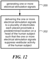
- One embodiment of the method for suppressing vestibular activity in a human subject of this description includes generating one or more electrical stimulation signals, step 200, Fig. 12 , and delivering one or more electrical stimulation signals to a plurality of electrodes each placed proximate a predetermined location on a head of the human subject such that the one or more electrical stimulation signals suppress vestibular activity of the human subject, step 202.
- the predetermined location is shown as the upper and lower mastoid, this is not a necessary limitation. In other examples, the predetermined location may be the temporal bone, the ear, or any desired location on head 14 of the human subject.
Landscapes
- Health & Medical Sciences (AREA)
- Life Sciences & Earth Sciences (AREA)
- General Health & Medical Sciences (AREA)
- Engineering & Computer Science (AREA)
- Biomedical Technology (AREA)
- Nuclear Medicine, Radiotherapy & Molecular Imaging (AREA)
- Radiology & Medical Imaging (AREA)
- Animal Behavior & Ethology (AREA)
- Public Health (AREA)
- Veterinary Medicine (AREA)
- Heart & Thoracic Surgery (AREA)
- Biophysics (AREA)
- Otolaryngology (AREA)
- Electrotherapy Devices (AREA)
Description
- This description relates to a system and method for suppressing vestibular activity of a human subject. The present invention relates to a system for suppressing vestibular activity as defined in
claim 1. - The ability to maintain spatial orientation and balance is the result of an elaborate synchronization of neural inputs from the vestibular, visual, and proprioceptive systems. When there is a mismatch among these signals or when input patterns from different senses do not correspond to stored expected sensory patterns, spatial disorientation may occur. The two primary conflicts occur between the visual and vestibular senses (i.e., intersensory conflict) and within the vestibular sense between the semicircular canals and otoliths (i.e., intrasensory conflict). Secondary conflict, however, may come from proprioceptive inputs that fail to synchronize with other sensory cues, particularly visual and peripheral proprioceptors connected to the vestibular system through vestibulospinal pathways. This creates the sensation commonly known as Motion Sickness. It includes a range of symptoms, from nausea and salivation to a sensation of warmth, tiredness, and other cognitive symptoms. In addition, sensory conflicts remain one of the most persistent issues facing advanced flight simulation development. Flight simulators have been shown to improve training effectiveness with considerably lower cost and risk than actual flight training. The capability to use simulation in training brings advantages in acquisition of skill sets, development of competencies, the reduction of errors in real environments, and decreased costs. The simulation environment, however, imposes limitations in matching real world sensory experiences. These limitations may manifest in the form of simulator-induced motion sickness, also known as simulator sickness (SS). SS is a variant of motion sickness resulting from exposure to simulated environments such as flight simulators, driving simulators and similar virtual, immersive environments. Whereas motion sickness refers to the adverse consequences of exposure to environments that physically put an individual in motion, SS is mainly the result of technological limitations in simulating dynamic environments that create a conflict in the body's self-motion perception sensors. Because of the wide variety of these symptoms, such as nausea, oculomotor disorders, disorientation, and the like, SS has also been described as "polygenic" since several factors have been identified including age, gender, simulator features, e.g., lag and field of view (FOV), and factors associated with the task performed, e.g., duration and degree of control. The theory of sensory conflict, also known as the sensory rearrangement or neural mismatch theory, indicates that sickness occurs when the pattern of inputs from different senses and within a single sensory modality do not correspond to the stored patterns of such inputs based on past experience, as a result of both cognitive and perceptual discrepancy. When SS symptoms develop, the value of the training experience and data derived during the experience may be compromised and in the most extreme cases results in negative transfer-of-training. Moreover, since symptoms may persist or recur spontaneously up to one day after exposure, various training centers routinely ground pilots for 6 to 24 hours after simulator time. These factors can lower the acceptance and overall utility of simulator enhanced learning. Conventional preventative pharmacological agents commonly used for motion sickness are typically ineffective to prevent SS and may be commonly associated with significant side effects after the simulated sessions including drowsiness and fatigue. Thus, simulator design may have a significant role in decreasing the incidence of SS. However, even with technological advances, imperfections including optical deficiencies, image scale factor magnifications, system time delays, limited field of view (FOV) displays head tracker inaccuracies, and the like, still remain unsolved limitations which contribute to SS.
-
U.S. Patent Publ. No. 2014/0127666 teaches systems and techniques for stimulating motion to a human subject alleviating motion sickness and directional cueing related to the vestibular system with coupling of galvanic vestibular stimulation GVS which relies on voltage and current unequally at two different points on a subject's head to cause a change in a vestibular response.U.S. Patent Publ. No. 2015/0039057 teaches an implantable nerve stimulation device sensor system. The nerve stimulation system includes an electrode array with electrodes that are invasively, surgically implanted in the human subject.Japanese Application No. 2006288665 CN2062231 teaches and discloses a complex device with gears, pendulums, double pole, single throw power switch and a light source which utilizes the swing of the hull of a boat to change intensity and a resistance which changes magnitude and current. Korean Publ. No.KR20160007957 US 2008/275513 also discloses a stimulation system known from the prior art. - Thus there is a need to mitigate motion sickness and/or SS by reducing or eliminating the mismatch between sensory cues inputs expected by a human subject and improve simulation based training.
- In one aspect, a system for suppressing vestibular activity of a human subject, the system is featured. The system includes an electronics module configured to generate one or more electrical stimulation signals. A plurality of electrodes each placed proximate a predetermined location on a head of a human subject is configured to deliver the one or more electrical stimulation signals to the predetermined location to suppress vestibular activity of the human subject.
- In one embodiment, the plurality of electrodes may be bi-laterally placed on opposing sides of the head. The predetermined location may include a mastoid process, the ear, or a temporal bone of the human subject. The one or more electrical stimulation signals may include one or more direct current (DC) signals. The one or more stimulation signals may include one or more DC signals each with an imposed carrier wave. The one or more stimulation signals may include one or more alternating current (AC) signals. The one or more electrical stimulation signals may be configured to hyperpolarize and/or depolarized cells located at each predetermined location to create a desired induced perception of motion. The plurality of electrodes may be configured to deliver electrical stimulation to suppress the vestibular system of the human subject to actual motion such that perception of motion of the human subject is reduced. The suppression of the vestibular system of the human subject to actual motion may decrease motion sickness that may arise from motion sensed by the human subject. The plurality of electrodes may include a first pair of electrodes placed on one side of the head of the human subject at the predetermined location, another pair of electrodes placed on an opposite side of the head of the human subject at the predetermined location, and a ground electrode placed on the head or neck of the human subject. Each pair of electrodes may include an electrode configured as positive electrode and an electrode configured as a negative electrode. The one or more electrical stimulation signals may be configured as one or more DC signals applied to each positive and negative electrode such that the one or more DC signals are transmitted from the positive electrode located at high predetermined location on the head of the human subject to the negative electrode located at a low location on the head of the human subject to suppress vestibular activity. The high predetermined location may include a high location on a mastoid process of the human subject and the low location includes a low location on mastoid process of the human subject. The one or more electrical stimulation signals may be configured as one or more DC signals each imposed carrier wave applied in phase to each positive and negative electrode such that the one or more DC signals with the imposed carrier waves are transmitted from the positive electrode at a high predetermined location to the negative electrode at a low predetermined location to suppress vestibular activity. The one or more electrical stimulation signals may be configured as one or more DC signals each imposed carrier wave applied temporally offset to each positive and negative electrode such that the one or more DC signals with the imposed carrier waves are transmitted from the positive electrode at a high predetermined location on one side of the head to the negative electrode at a low predetermined location on an opposite side of the head to suppress vestibular activity. The high predetermined location may include a high location on mastoid process and the low predetermined location includes a low location on mastoid process of the human subject. The plurality of electrodes may include one electrode placed on one side of the head of the human subject at the predetermined location and another electrode is placed on an opposite side of the head of the human subject at the predetermined location. The one or more electrical stimulation signals may be configured as one or more AC signals applied to the electrode placed on one side of the head and the electrode placed on one the opposite side of the head such that the one or more AC signals are transmitted back and forth from one electrode at its maximum current at the predetermined location on one side of the head to the another electrode at its maximum negative current at the predetermined location on an opposite side of the head of the human subject to suppress vestibular activity.
- As disclosed herein, all examples of methods for suppressing vestibular activity of a human subject are for use with the system for suppressing vestibular activity and are of explanatory nature.
- In another aspect, a method for suppressing vestibular activity of a human subject is featured. The method includes generating one or more electrical stimulation signals, and delivering the one or more electrical stimulation signals to a plurality of electrodes each placed proximate a predetermined location on a head of the human subject such that the one or more electrical stimulation signals suppress vestibular activity of the human subject.
- In one embodiment, the method may include bilaterally placing the electrodes on opposing sides of the head of the human subject at the predetermined location. The one or more electrical stimulation signals may hyperpolarize and/or may depolarize cells located at each predetermined location to create a desired induced perception of motion. The method may include delivering electrical stimulation to suppress the vestibular system of the human subject to actual motion such that perception of motion of the human subject is reduced. The suppression of the vestibular system of the human subject to actual motion may decrease motion sickness that may arise from motion sensed by the human subject. The one or more electrical stimulation signals may include one or more direct current (DC) signals. The one or more stimulation signals may include one or more DC signals each with an imposed carrier wave. The one or more stimulation signals may include one or more alternating current (AC) signals. The one more electrical stimulation signals may include one or more DC signals transmitted from a positive electrode at a high predetermined location on one side of the head to the negative electrode at a low predetermined location on an opposite side of the head to suppress vestibular activity. The one more electrical stimulation signals may include one or more DC signals with the imposed carrier waves transmitted in phase from a positive electrode at a high predetermined location on one side of the head to the negative electrode at a low predetermined location on an opposite side of the head to suppress vestibular activity. The one more electrical stimulation signals may include one or more DC signals with the imposed carrier waves transmitted temporally offset from a positive electrode at a high predetermined location on one side of the head to the negative electrode at a low predetermined location on an opposite side of the head to suppress vestibular activity. The one more electrical stimulation signals may include one or more AC signals transmitted from an electrode on one side of the head at the determined location to an electrode on an opposite side of the head to suppress vestibular activity.
- Other objects, features and advantages will occur to those skilled in the art from the following description of a preferred embodiment and the accompanying drawings, in which:
-
Fig. 1 is a schematic block diagram showing the primary components of one embodiment of the system for suppressing vestibular activity of a human subject of this description; -
Fig. 2 shows in further detail the primary components associated with one embodiment of the electronics module shown inFig. 1 ; -
Fig. 3 shows in further detail one example of the electronics utilized by the electronics circuit board of the electronics module shown inFigs. 1 and2 ; -
Fig. 4 shows in further detail one example of the electronics utilized by the electronics circuit board of the electronics module shown inFigs. 1 and2 ; -
Fig. 5 shows one example of one preferred location for the placement of electrodes shown inFig. 1 on the head of a human subject; -
Fig. 6 shows examples of electrodes which may be utilized by the system shown inFig. 1 ; -
Fig. 7 shows examples of galvanic vestibular stimulation which may used to mimic the body's natural reaction to head acceleration/tilt; -
Fig. 8 is a schematic block diagram showing the primary components of another embodiment of the system for suppressing vestibular activity of a human subject; -
Fig. 9 is a schematic block diagram showing the primary components of another embodiment of the system for suppressing vestibular activity of a human subject; -
Fig. 10 is a schematic block diagram showing primary components of another embodiment of the system for suppressing vestibular activity of a human subject; -
Fig. 11 is a schematic block diagram of another embodiment of the system for suppressing vestibular activity of a human subject; and -
Fig. 12 is a schematic block diagram showing the primary steps associated with one embodiment of the method for suppressing vestibular activity of a human subject according to the description. - The present invention is set out in the appended claims and pertains to a system for suppressing vestibular activity of a human subject.
- There is shown in
Fig. 1 one embodiment forsystem 10 and the method thereof for suppressing vestibular activity of a human subject.System 10 includeselectronics module 12 configured to generate one or more stimulation signals which are applied to electrodes at predetermined locations ofhead 14 of the human subject to suppress vestibular activity as will be discussed in detail below.Fig. 2 shows examples ofelectronics module 12 which is capable of generating the one or more electrical stimulation signals, e.g. up to about 2.5 mA in a DC mode or an AC mode with a frequency between about 300 Hz and 12 kHz usingfrequency control 16 andamplitude control 18.Electronics module 12 also preferably includesdisplay 20 which displays the current and/or voltage of the one or more stimulation signals. In one design,electronics module 12 may be operated with batteries, e.g., 6 AA batteries indicated at 22.Electronics module 12 also preferably includeselectronics board 24 which is coupled tofrequency control 16,amplitude 18,display 20, andconnectors 52.Electronics board 24 is configured to generate the one or more electrical stimulation signals.Figs. 3 and4 show in further detail examples ofelectronic circuitry electronics board 24 ofelectronics module 12,Figs. 1 and2 , which may be used to generate the one or more electrical stimulation signals to suppress vestibular activity. -
System 10,Fig. 1 , also includes a plurality of electrodes each placed proximate a predetermined location onhead 14 of the human subject configured to deliver the one or more electrical stimulation signals to the predetermined location onhead 14 to suppress vestibular activity. In the example shown inFig. 1 ,system 10 includes plurality ofelectrodes 22 placed proximate a predetermined on one side ofhead 14 and plurality ofelectrodes 26 bilaterally placed proximate a predetermined location on an opposite sided ofhead 14 as shown, e.g., proximate themastoid process 40,Fig. 5 , and preferably within the area indicated at 42 which is located directly behind the external ear as shown. In other examples, the predetermined location on each side ofhead 14 may the temporal bone, indicated at 46 -
Fig. 6 shows exemplary electrodes which may be utilized (available from MFI Medical Equipment San Diego, CA) which are preferably coupled toconnectors 52,Fig. 2 . - In one example, one of the electrodes of the plurality of
electrodes 22,Fig. 1 , e.g.,electrode 50, may be configured as a positive electrode by connecting it to contact 54 which outputs positive DC or AC current generated byelectronics module 12. The other of plurality ofelectrodes 22,Fig. 1 ,e.g. electrode 54, may be configured as a negative electrode by connecting it to contact 58 which outputs negative DC or AC current generated byelectronics module 12. Similarly, one of the electrodes of the plurality ofelectrodes 26, e.g.,electrode 60, may be configured as a positive electrode by connecting it to contact 62 which outputs positive DC or AC current or voltage generated byelectronics module 12 and the other of the plurality ofelectrodes 22, e.g.,electrode 66, may be configured as a negative electrode by connecting it tonegative contact 68 which outputs negative DC or AC current or voltage generated byelectronics module 12. Preferably,system 10 includesground electrode 70 preferably placed proximate the nape of the neck as shown coupled toground contact 72. - The one or more electrical stimulation signals generated by
electronics module 12 toelectrodes head 14 at the predetermined location and the one or more electrical stimulation signals applied toelectrodes head 14 of the human subject suppresses vestibular activity. - Preferably, the vestibular system of the human subject is suppressed to actual motion by
system 10 and the method thereof such that the perception of motion of the human subject is reduced. Suppression of the vestibular system of the human subject to actual motion preferably decreases motion sickness and/or SS that may arise from motion sensed by the human subject. By suppressing vestibular activity,system 10 and the method thereof may mitigate motion sickness and/or SS by reducing or eliminating the mismatch between sensory cues inputs expected by a human subject and improve simulation based training. - The one or more electrical stimulation signals generated by
electronics module 12 and delivered byelectrodes head 14 as discussed above to create a desired induced perception of motion.System 10 and the method thereof mimics the polarization of the cells caused by motion with the application of small amounts of external electrical stimulation by the one or more electrical stimulation signals. By judicious application of the one or more electrical stimulation signals at appropriate external predetermined locations, the cells on each side ofhead 14 are preferably hyperpolarized and/or depolarized thereby using their natural response to create the desired signals. Unlike conventional systems and methods which may rely on swamping the signals sent the brain,system 10 and the method thereof works with the healthy vestibular system of the human subject to create a transient signal associated with acceleration of the head. Upon cessation of stimulation, the cells repolarize to their "at rest" condition within a few pulses, requiring less than a second to return to their pre-stimulation condition. SeeFig. 7 . - In one example, the one or more electrical stimulation signals stimulation signals generated by
electronics module 12,Figs. 1-4 , to suppress vestibular activity may include one or more direct current (DC) signals, one or more DC signals with an imposed carrier waves or one or more alternating current (AC) signals. - For example,
electronics module 12,Fig. 8 , where like parts have been given like numbers, may generate one or more electrical stimulation signals to suppress vestibular activity configured aspositive DC signal 80 which is appliedelectrode 50 preferably located at an upper mastoid location of thehead 14 as shown, e.g., atlocation 43,Fig. 5 ofarea 42.Electronics module 12 may also generatenegative DC signal 82 which is applied toelectrode 52 preferably located at a lower mastoid position on thehead 14 as shown, e.g., atlocation 45 ofarea 42. The one or more electrical stimulation signals in this example are transmitted from the upper mastoid location of the left side ofhead 14 to lower mastoid position onhead 14 as shown byarrow 87 to suppress vestibular activity. - Similarly,
electronics module 12 may generate one or more electrical stimulation signals to suppress vestibular activity configured aspositive DC signal 84 which is appliedelectrode 60 preferably located at an upper mastoid location of thehead 14, as discussed above.Electronics module 12 may also generatenegative DC signal 86 which is applied toelectrode 66 located at a lower mastoid position on thehead 14 as shown, e.g., as discussed above. The one or more electrical stimulation signals in this example are transmitted from the upper mastoid location of thehead 14 to lower mastoid position on the head, as shown byarrow 89, to suppress vestibular activity. -
Electronics module 12,Fig. 9 , where like parts have been given like numbers, may generate one or more electrical stimulation signals to suppress vestibular activity configured as DC signal 90 with imposedpositive carrier wave 92 which is appliedelectrode 50 preferably located at an upper mastoid location of thehead 14 as shown, similarly as discussed above. Imposedcarrier wave 92 modulates the current applied to electrode 50 between 0 amps, indicated at 93, and the maximum positive current, indicated at 95.Electronics module 12 may also generateDC signal 90 with imposednegative carrier wave 94 which is applied toelectrode 52 located at a lower mastoid position on thehead 14 as shown, similar as discussed above. Imposednegative carrier wave 94 modulates the current applied to electrode 52 between 0 amps, indicated at 95, and the maximum negative current, indicated at 97. In this example, imposedcarrier waves electrode 50 toelectrode 52, as shown byarrow 97, to suppress vestibular activity. - Similarly,
electronics module 12,Fig 9 , may generate one or more electrical stimulation signals to suppress vestibular activity configured as configured as DC signal 100 with imposedpositive carrier wave 102 which is appliedelectrode 60 preferably located at an upper mastoid location of thehead 14 as shown. Imposedpositive carrier wave 102 preferably modulates the current applied to electrode 60 between 0 amps, indicated at 101, and the maximum positive current, indicated at 103.Electronics module 12,Fig 9 , may also generate DC signal 100 with imposednegative carrier wave 104 which is applied toelectrode 66 located at a lower mastoid position on thehead 14 as shown, as discussed above. Imposednegative carrier wave 104 modulates the current applied to electrode 66 between 0 amps, indicated at 101, and the maximum negative current, indicated at 105. In this example,carrier waves electrode 60 toelectrode 66 as shown byarrow 99, to suppress vestibular activity. - In another example,
electronics module 12,Fig. 10 , where like parts have been given like numbers may generateDC signal 90 with imposedcarrier waves carrier waves electrode 50 at its maximum current on one side ofhead 14 at a higher mastoid position to electrode 66 at zero current on an opposite side of head 14 a lower mastoid position, as shown byarrow 110, and fromelectrode 60 at its maximum current on side ofhead 14 at a higher mastoid position to electrode 52 at zero current, on an opposite side ofhead 14 at a lower mastoid position, as shown byarrow 112, to suppress vestibular activity. -
Electronics module 12,Fig. 11 , where like parts have been given like numbers may generate one or more electrical stimulation signals to suppress vestibular activity configured one or more AC signals. In one example,electronics module 12 preferably generates AC signal 130 bycontact 132 which is applied toelectrode 134 located on one side ofhead 14, e.g., atlocation 43Fig. 5 , ofarea 42 of the mastoid as shown, or any desired location on one side ofhead 14.Electronics module 12 also generates AC signal 136 by contact 138 which is temporally offset, e.g., 180 degrees out of phase, withAC signal 130.Ground electrode 70 is coupled toground contact 72. The result is the one or more AC signals are transmitted back and forth from one ofelectrodes electrodes arrow 142, to suppress vestibular activity. - One embodiment of the method for suppressing vestibular activity in a human subject of this description includes generating one or more electrical stimulation signals,
step 200,Fig. 12 , and delivering one or more electrical stimulation signals to a plurality of electrodes each placed proximate a predetermined location on a head of the human subject such that the one or more electrical stimulation signals suppress vestibular activity of the human subject,step 202. - Although as discussed above with reference to one or more of
Figs. 8-11 , the predetermined location is shown as the upper and lower mastoid, this is not a necessary limitation. In other examples, the predetermined location may be the temporal bone, the ear, or any desired location onhead 14 of the human subject.
Claims (8)
- A system for suppressing vestibular activity of a human subject, the system comprising:an electronics module (12) configured to generate at least first and second electrical stimulation signals, the first electrical stimulation signal including a first carrier signal and the second electrical stimulation signal including a second carrier signal, said first electrical stimulation signal being the first carrier signal imposed on a positive biased DC signal and said second electrical stimulation signal being the second carrier signal imposed on a negative biased DC signal;a plurality of electrodes (22, 26) including a first electrode (50, 60) configured to be placed at an upper mastoid position on a side of a head (14) of the human subject and a second electrode (54, 66) configured to be placed at a lower mastoid position on the same side of the head (14) of the human subject, andwherein the electronics module is configured to modulate the current applied to respective electrodes (50, 54, 60, 66) between 0 amps and a maximum positive/negative current and apply the first electrical stimulation signal to the first electrode while concurrently applying the second electrical stimulation signal to the second electrode to suppress vestibular activity of the human subject, the one or more electrical stimulation signals configured to hyperpolarize and/or depolarize cells located proximate the stimulation regions to suppress vestibular activity.
- The system of claim 1 in which the plurality of electrodes (22, 26) are bi-laterally configured to be placed on opposite sides of the head.
- The system of claim 1 in which the plurality of electrodes (22, 26) is configured to deliver electrical stimulation to suppress the vestibular system of the human subject to actual motion such that perception of motion of the human subject is reduced.
- The system of claim 3 in which the suppression of the vestibular system of the human subject to actual motion decreases motion sickness that may arise from motion sensed by the human subject.
- The system of claim 1 in which the plurality of electrodes (22, 26) includes a first pair of electrodes (50, 54) configured to be placed on one side of the head (14) of the human subject, another pair of electrodes (60, 66) configured to be placed on an opposite side of the head of the human subject, and a ground electrode (70) placed on the head or neck of the human subject.
- The system of claim 1 in which the one or more electrical stimulation signals are applied in phase to each first (50, 60) and second electrode (54, 66) such that the one or more electrical stimulation signals are transmitted from the first electrode (50, 60) to the second electrode (54, 66) to suppress vestibular activity.
- The system of claim 1 in which the one or more electrical stimulation signals are applied temporally offset to each first (50, 60) and second electrode (54, 66) such that the one or more electrical stimulation signals are transmitted from the first electrode (50, 60) to the second electrode (54, 66) to suppress vestibular activity.
- The system of claim 1 in which the plurality of electrodes (22, 26) include one electrode (50 or 60) configured to be placed on one side of the head (14) of the human subject and another electrode (54, 66) configured to be placed on an opposite side of the head (14) of the human subject.
Applications Claiming Priority (2)
| Application Number | Priority Date | Filing Date | Title |
|---|---|---|---|
| US15/079,445 US10207101B2 (en) | 2016-03-24 | 2016-03-24 | System and method for suppressing vestibular activity of a human subject |
| PCT/US2017/016694 WO2017165001A1 (en) | 2016-03-24 | 2017-02-06 | System and method for suppressing vestibular activity of a human subject |
Publications (3)
| Publication Number | Publication Date |
|---|---|
| EP3432974A1 EP3432974A1 (en) | 2019-01-30 |
| EP3432974A4 EP3432974A4 (en) | 2019-10-30 |
| EP3432974B1 true EP3432974B1 (en) | 2025-04-02 |
Family
ID=59897451
Family Applications (1)
| Application Number | Title | Priority Date | Filing Date |
|---|---|---|---|
| EP17770755.1A Active EP3432974B1 (en) | 2016-03-24 | 2017-02-06 | System for suppressing vestibular activity of a human subject |
Country Status (11)
| Country | Link |
|---|---|
| US (2) | US10207101B2 (en) |
| EP (1) | EP3432974B1 (en) |
| JP (2) | JP6914958B2 (en) |
| KR (2) | KR20200122420A (en) |
| CN (1) | CN108883276B (en) |
| AU (2) | AU2017238038B2 (en) |
| CA (1) | CA3015876C (en) |
| ES (1) | ES3031419T3 (en) |
| FI (1) | FI3432974T3 (en) |
| PL (1) | PL3432974T3 (en) |
| WO (1) | WO2017165001A1 (en) |
Families Citing this family (8)
| Publication number | Priority date | Publication date | Assignee | Title |
|---|---|---|---|---|
| US10945880B2 (en) | 2015-09-04 | 2021-03-16 | Scion Neurostim, Llc | Systems, devices and methods for galvanic vestibular stimulation having an envelope modulation |
| US10207101B2 (en) * | 2016-03-24 | 2019-02-19 | Vivonics, Inc. | System and method for suppressing vestibular activity of a human subject |
| MX2019005432A (en) * | 2019-05-09 | 2020-11-10 | Benemerita Univ Autonoma De Puebla Star | Device for the use of vestibular galvanic stimulation for pilot training and the correction of the position and sight fixation in microgravity. |
| US20210046312A1 (en) * | 2019-08-13 | 2021-02-18 | Neurovalens, Ltd. | Devices, systems and methods for synchronous binaural vestibular nerve stimulation |
| JP6903109B2 (en) * | 2019-09-30 | 2021-07-14 | 株式会社菊池製作所 | Vestibular electrical stimulator |
| US11806530B2 (en) | 2020-04-21 | 2023-11-07 | Cochlear Limited | Balance compensation |
| WO2022018531A1 (en) | 2020-07-24 | 2022-01-27 | Cochlear Limited | Vestibular clinical support system functionality |
| CN116510176B (en) * | 2023-04-17 | 2024-02-06 | 维看科技(天津)有限公司 | Information processing apparatus |
Citations (1)
| Publication number | Priority date | Publication date | Assignee | Title |
|---|---|---|---|---|
| US20080275513A1 (en) * | 1999-05-05 | 2008-11-06 | Ric Investments, Llc. | Vestibular Stimulation System and Method |
Family Cites Families (30)
| Publication number | Priority date | Publication date | Assignee | Title |
|---|---|---|---|---|
| AT315357B (en) * | 1970-09-08 | 1974-05-27 | Rodler Ing Hans | Electromedical apparatus for generating interference and beat currents |
| US4667676A (en) * | 1985-06-17 | 1987-05-26 | Audimax, Inc. | Method of evaluating the vestibular system |
| CN2062231U (en) * | 1989-07-28 | 1990-09-19 | 天津市第二医学院附属第一中心医院 | Therapeutic device for motion sickness |
| CN1045540C (en) * | 1995-07-24 | 1999-10-13 | 天津市第一中心医院 | Electronic vestibule-regulating device |
| EA001618B1 (en) * | 1996-05-31 | 2001-06-25 | Масаюки Мацуура | Method, apparatus and system for low-frequency therapy |
| CA2343731A1 (en) | 1998-09-09 | 2000-03-16 | J. Timothy Inglis | Galvanic vestibular stimulation system and method |
| JP2003135607A (en) * | 2001-11-06 | 2003-05-13 | Heiwa Denshi Kogyo Kk | Low frequency medical treating system |
| JP4031719B2 (en) * | 2003-03-06 | 2008-01-09 | ヒロセ電機株式会社 | Interference low frequency treatment device |
| JP2004358078A (en) * | 2003-06-06 | 2004-12-24 | National Cardiovascular Center | Neuron and angiogenesis stimulator |
| US20070250119A1 (en) * | 2005-01-11 | 2007-10-25 | Wicab, Inc. | Systems and methods for altering brain and body functions and for treating conditions and diseases of the same |
| US8788044B2 (en) | 2005-01-21 | 2014-07-22 | Michael Sasha John | Systems and methods for tissue stimulation in medical treatment |
| JP4444872B2 (en) | 2005-04-08 | 2010-03-31 | 日本電信電話株式会社 | Motion control device, current command value input device, and program |
| JP4781799B2 (en) * | 2005-11-30 | 2011-09-28 | 日本電信電話株式会社 | Electrical stimulator |
| EP2076306A4 (en) * | 2006-09-01 | 2011-11-23 | Gsmo Pty Ltd | Motion sickness device |
| US7949403B2 (en) * | 2007-02-27 | 2011-05-24 | Accelerated Care Plus Corp. | Electrical stimulation device and method for the treatment of neurological disorders |
| US10076655B2 (en) * | 2007-09-21 | 2018-09-18 | Koninklijke Philips N.V. | Vestibular stimulation system |
| US8630714B1 (en) * | 2008-06-30 | 2014-01-14 | Electrostim Medical Services, Inc. | Bone growth stimulation using a constant current capacitively coupled stimulator |
| US8326415B2 (en) | 2008-10-31 | 2012-12-04 | The Invention Science Fund / LLC | System for altering motional response to sensory input |
| AU2010221761B2 (en) | 2009-03-05 | 2014-04-24 | Infoscitex Corporation | Galvanic vestibular stimulation system and method of use for simulation, directional cueing, and alleviating motion-related sickness |
| EP2493558A1 (en) * | 2009-10-28 | 2012-09-05 | Koninklijke Philips Electronics N.V. | Method of alleviating motion sickness |
| CN101773702B (en) * | 2010-01-04 | 2012-10-10 | 北京航空航天大学 | Human body sensory conflict inducing device |
| US9242094B2 (en) * | 2010-01-12 | 2016-01-26 | The Johns Hopkins University | Implantable vestibular prosthesis |
| EP2804661A4 (en) * | 2012-01-17 | 2015-05-27 | Med El Elektromed Geraete Gmbh | IMPLANTABLE VESTIBULAR PROSTHESIS SYSTEM HAVING ENERGY SAVING MODE WITH PROGRESSIVE START-UP AND PILOT STOP |
| US8855774B2 (en) * | 2012-09-14 | 2014-10-07 | Benemerita Universidad Autonoma De Puebla | Vestibular prosthesis |
| KR101428680B1 (en) | 2012-09-27 | 2014-08-11 | 원광대학교산학협력단 | System for treatment of vestibular symptoms by using electrical stimulation of cerebral cortex |
| EP2961474B1 (en) * | 2013-03-01 | 2022-12-14 | The Regents of the University of California | Cosmetic method for altering body mass composition using galvanic vestibular stimulation |
| US20160007921A1 (en) | 2014-07-10 | 2016-01-14 | Vivonics, Inc. | Head-mounted neurological assessment system |
| KR101635266B1 (en) * | 2014-07-10 | 2016-07-01 | 한림대학교 산학협력단 | Galvanic vestibular stimulation system for reducing cyber-sickness in 3d virtual reality environment and method thereof |
| CN104524691A (en) * | 2015-01-27 | 2015-04-22 | 中国人民解放军海军总医院 | Vestibular illusion inducing device |
| US10207101B2 (en) * | 2016-03-24 | 2019-02-19 | Vivonics, Inc. | System and method for suppressing vestibular activity of a human subject |
-
2016
- 2016-03-24 US US15/079,445 patent/US10207101B2/en active Active
-
2017
- 2017-02-06 PL PL17770755.1T patent/PL3432974T3/en unknown
- 2017-02-06 AU AU2017238038A patent/AU2017238038B2/en active Active
- 2017-02-06 CN CN201780018982.9A patent/CN108883276B/en active Active
- 2017-02-06 JP JP2018549937A patent/JP6914958B2/en active Active
- 2017-02-06 CA CA3015876A patent/CA3015876C/en active Active
- 2017-02-06 FI FIEP17770755.1T patent/FI3432974T3/en active
- 2017-02-06 KR KR1020207029998A patent/KR20200122420A/en not_active Ceased
- 2017-02-06 ES ES17770755T patent/ES3031419T3/en active Active
- 2017-02-06 KR KR1020187030614A patent/KR102170138B1/en active Active
- 2017-02-06 EP EP17770755.1A patent/EP3432974B1/en active Active
- 2017-02-06 WO PCT/US2017/016694 patent/WO2017165001A1/en not_active Ceased
-
2019
- 2019-01-17 US US16/250,171 patent/US20190151645A1/en not_active Abandoned
- 2019-11-13 AU AU2019264572A patent/AU2019264572B9/en active Active
-
2021
- 2021-07-13 JP JP2021115683A patent/JP2022008274A/en active Pending
Patent Citations (1)
| Publication number | Priority date | Publication date | Assignee | Title |
|---|---|---|---|---|
| US20080275513A1 (en) * | 1999-05-05 | 2008-11-06 | Ric Investments, Llc. | Vestibular Stimulation System and Method |
Also Published As
| Publication number | Publication date |
|---|---|
| US20170274211A1 (en) | 2017-09-28 |
| JP2019509142A (en) | 2019-04-04 |
| CN108883276B (en) | 2022-07-19 |
| EP3432974A1 (en) | 2019-01-30 |
| AU2017238038B2 (en) | 2019-08-22 |
| CN108883276A (en) | 2018-11-23 |
| ES3031419T3 (en) | 2025-07-08 |
| FI3432974T3 (en) | 2025-05-09 |
| JP6914958B2 (en) | 2021-08-04 |
| US20190151645A1 (en) | 2019-05-23 |
| KR20200122420A (en) | 2020-10-27 |
| AU2019264572B2 (en) | 2021-04-15 |
| PL3432974T3 (en) | 2025-07-28 |
| AU2019264572A1 (en) | 2019-12-05 |
| CA3015876C (en) | 2022-09-27 |
| JP2022008274A (en) | 2022-01-13 |
| AU2017238038A1 (en) | 2018-10-11 |
| EP3432974A4 (en) | 2019-10-30 |
| AU2019264572B9 (en) | 2021-08-05 |
| KR20180127441A (en) | 2018-11-28 |
| WO2017165001A1 (en) | 2017-09-28 |
| CA3015876A1 (en) | 2017-09-28 |
| US10207101B2 (en) | 2019-02-19 |
| KR102170138B1 (en) | 2020-10-26 |
| WO2017165001A8 (en) | 2018-10-11 |
Similar Documents
| Publication | Publication Date | Title |
|---|---|---|
| AU2019264572B9 (en) | System and method for suppressing vestibular activity of a human subject | |
| AU2010221761B2 (en) | Galvanic vestibular stimulation system and method of use for simulation, directional cueing, and alleviating motion-related sickness | |
| US11273344B2 (en) | Multimodal sensory feedback system and method for treatment and assessment of disequilibrium, balance and motion disorders | |
| Weech et al. | Vection latency is reduced by bone-conducted vibration and noisy galvanic vestibular stimulation | |
| WO1998037803A1 (en) | Multimodal stimulation in virtual environments | |
| Yang et al. | Comparison of postural responses to galvanic vestibular stimulation between pilots and the general populace | |
| Weiland et al. | Smart image processing system for retinal prosthesis | |
| Morrow et al. | The effects of duration and frequency on the perception of vibrotactile stimulation on the neck | |
| US11721233B2 (en) | Device for the use of vestibular galvanic stimulation for pilot training and the correction of the position and sight fixation in microgravity | |
| CN211584798U (en) | Synchronous multimode treatment system based on VR-TMS technology | |
| RU2500375C1 (en) | Device for automatic correction of individual sight alignment in visual motion control in microgravitation environment | |
| Kim et al. | Against the leans: overcoming spatial disorientation through galvanic vestibular stimulation | |
| US20260003431A1 (en) | Method and apparatus for multi-dimensional vestibular electrophysiologic interfacing | |
| US20260133636A1 (en) | Method and apparatus for multi-dimensional vestibular electrophysiologic interfacing | |
| Aoyama | Novel display using percutaneous electrical stimulation for virtual reality | |
| US20020173823A1 (en) | Sense organs synthesizer | |
| Cheung et al. | Using tactile cueing to enhance spatial awareness under degraded visual environment | |
| Weech | The impact of noisy vestibular stimulation on self-motion phenomena | |
| Kang et al. | Effects of ramped GVS parameter combinations on vestibular perception and their application in a Virtual Reality flight simulator | |
| Oman et al. | 1.2 Experiment Designation VOILA 1.3 Functional Objective Designation N/A 1.4 Title:“Visuomotor and Orientation Investigations in Long-Duration Astronauts”(VOILA) 1.5 Name of Organizations Conducting the Research | |
| Cholewiak et al. | Studies of the Interactions Between Vestibular Function and Tactual Orientation Display Systems | |
| Kuroki et al. | Somatotopic distortion of tactile temporal interval estimation | |
| Raj et al. | Perceptual Tasks |
Legal Events
| Date | Code | Title | Description |
|---|---|---|---|
| STAA | Information on the status of an ep patent application or granted ep patent |
Free format text: STATUS: THE INTERNATIONAL PUBLICATION HAS BEEN MADE |
|
| PUAI | Public reference made under article 153(3) epc to a published international application that has entered the european phase |
Free format text: ORIGINAL CODE: 0009012 |
|
| STAA | Information on the status of an ep patent application or granted ep patent |
Free format text: STATUS: REQUEST FOR EXAMINATION WAS MADE |
|
| 17P | Request for examination filed |
Effective date: 20180924 |
|
| AK | Designated contracting states |
Kind code of ref document: A1 Designated state(s): AL AT BE BG CH CY CZ DE DK EE ES FI FR GB GR HR HU IE IS IT LI LT LU LV MC MK MT NL NO PL PT RO RS SE SI SK SM TR |
|
| AX | Request for extension of the european patent |
Extension state: BA ME |
|
| RIN1 | Information on inventor provided before grant (corrected) |
Inventor name: GALEA, ANNA M. Inventor name: STEPANEK, JAN Inventor name: SCHEIBLER, LINSEY S. Inventor name: OAKLEY HOLBERT, SARAH Inventor name: COCCO, DANIELA Inventor name: BOGLE, JAMIE M. Inventor name: PRADHAN, GAURAV N. Inventor name: CEVETTE, MICHAEL J. |
|
| DAV | Request for validation of the european patent (deleted) | ||
| DAX | Request for extension of the european patent (deleted) | ||
| A4 | Supplementary search report drawn up and despatched |
Effective date: 20190926 |
|
| RIC1 | Information provided on ipc code assigned before grant |
Ipc: A61N 1/36 20060101AFI20190920BHEP |
|
| STAA | Information on the status of an ep patent application or granted ep patent |
Free format text: STATUS: EXAMINATION IS IN PROGRESS |
|
| 17Q | First examination report despatched |
Effective date: 20200518 |
|
| 19U | Interruption of proceedings before grant |
Effective date: 20221030 |
|
| 19W | Proceedings resumed before grant after interruption of proceedings |
Effective date: 20230301 |
|
| P01 | Opt-out of the competence of the unified patent court (upc) registered |
Effective date: 20230523 |
|
| GRAP | Despatch of communication of intention to grant a patent |
Free format text: ORIGINAL CODE: EPIDOSNIGR1 |
|
| STAA | Information on the status of an ep patent application or granted ep patent |
Free format text: STATUS: GRANT OF PATENT IS INTENDED |
|
| INTG | Intention to grant announced |
Effective date: 20241025 |
|
| GRAS | Grant fee paid |
Free format text: ORIGINAL CODE: EPIDOSNIGR3 |
|
| GRAA | (expected) grant |
Free format text: ORIGINAL CODE: 0009210 |
|
| STAA | Information on the status of an ep patent application or granted ep patent |
Free format text: STATUS: THE PATENT HAS BEEN GRANTED |
|
| AK | Designated contracting states |
Kind code of ref document: B1 Designated state(s): AL AT BE BG CH CY CZ DE DK EE ES FI FR GB GR HR HU IE IS IT LI LT LU LV MC MK MT NL NO PL PT RO RS SE SI SK SM TR |
|
| REG | Reference to a national code |
Ref country code: GB Ref legal event code: FG4D |
|
| REG | Reference to a national code |
Ref country code: CH Ref legal event code: EP |
|
| REG | Reference to a national code |
Ref country code: IE Ref legal event code: FG4D |
|
| REG | Reference to a national code |
Ref country code: DE Ref legal event code: R096 Ref document number: 602017088700 Country of ref document: DE |
|
| REG | Reference to a national code |
Ref country code: FI Ref legal event code: FGE |
|
| REG | Reference to a national code |
Ref country code: SE Ref legal event code: TRGR |
|
| REG | Reference to a national code |
Ref country code: ES Ref legal event code: FG2A Ref document number: 3031419 Country of ref document: ES Kind code of ref document: T3 Effective date: 20250708 |
|
| REG | Reference to a national code |
Ref country code: NL Ref legal event code: MP Effective date: 20250402 |
|
| PG25 | Lapsed in a contracting state [announced via postgrant information from national office to epo] |
Ref country code: NL Free format text: LAPSE BECAUSE OF FAILURE TO SUBMIT A TRANSLATION OF THE DESCRIPTION OR TO PAY THE FEE WITHIN THE PRESCRIBED TIME-LIMIT Effective date: 20250402 |
|
| REG | Reference to a national code |
Ref country code: AT Ref legal event code: MK05 Ref document number: 1780703 Country of ref document: AT Kind code of ref document: T Effective date: 20250402 |
|
| PG25 | Lapsed in a contracting state [announced via postgrant information from national office to epo] |
Ref country code: PT Free format text: LAPSE BECAUSE OF FAILURE TO SUBMIT A TRANSLATION OF THE DESCRIPTION OR TO PAY THE FEE WITHIN THE PRESCRIBED TIME-LIMIT Effective date: 20250804 |
|
| REG | Reference to a national code |
Ref country code: LT Ref legal event code: MG9D |
|
| PG25 | Lapsed in a contracting state [announced via postgrant information from national office to epo] |
Ref country code: GR Free format text: LAPSE BECAUSE OF FAILURE TO SUBMIT A TRANSLATION OF THE DESCRIPTION OR TO PAY THE FEE WITHIN THE PRESCRIBED TIME-LIMIT Effective date: 20250703 |
|
| PG25 | Lapsed in a contracting state [announced via postgrant information from national office to epo] |
Ref country code: BG Free format text: LAPSE BECAUSE OF FAILURE TO SUBMIT A TRANSLATION OF THE DESCRIPTION OR TO PAY THE FEE WITHIN THE PRESCRIBED TIME-LIMIT Effective date: 20250402 |
|
| PG25 | Lapsed in a contracting state [announced via postgrant information from national office to epo] |
Ref country code: HR Free format text: LAPSE BECAUSE OF FAILURE TO SUBMIT A TRANSLATION OF THE DESCRIPTION OR TO PAY THE FEE WITHIN THE PRESCRIBED TIME-LIMIT Effective date: 20250402 |
|
| PG25 | Lapsed in a contracting state [announced via postgrant information from national office to epo] |
Ref country code: AT Free format text: LAPSE BECAUSE OF FAILURE TO SUBMIT A TRANSLATION OF THE DESCRIPTION OR TO PAY THE FEE WITHIN THE PRESCRIBED TIME-LIMIT Effective date: 20250402 |
|
| PG25 | Lapsed in a contracting state [announced via postgrant information from national office to epo] |
Ref country code: RS Free format text: LAPSE BECAUSE OF FAILURE TO SUBMIT A TRANSLATION OF THE DESCRIPTION OR TO PAY THE FEE WITHIN THE PRESCRIBED TIME-LIMIT Effective date: 20250702 |
|
| PG25 | Lapsed in a contracting state [announced via postgrant information from national office to epo] |
Ref country code: IS Free format text: LAPSE BECAUSE OF FAILURE TO SUBMIT A TRANSLATION OF THE DESCRIPTION OR TO PAY THE FEE WITHIN THE PRESCRIBED TIME-LIMIT Effective date: 20250802 |
|
| PG25 | Lapsed in a contracting state [announced via postgrant information from national office to epo] |
Ref country code: LV Free format text: LAPSE BECAUSE OF FAILURE TO SUBMIT A TRANSLATION OF THE DESCRIPTION OR TO PAY THE FEE WITHIN THE PRESCRIBED TIME-LIMIT Effective date: 20250402 |
|
| REG | Reference to a national code |
Ref country code: DE Ref legal event code: R097 Ref document number: 602017088700 Country of ref document: DE |
|
| PG25 | Lapsed in a contracting state [announced via postgrant information from national office to epo] |
Ref country code: DK Free format text: LAPSE BECAUSE OF FAILURE TO SUBMIT A TRANSLATION OF THE DESCRIPTION OR TO PAY THE FEE WITHIN THE PRESCRIBED TIME-LIMIT Effective date: 20250402 Ref country code: SM Free format text: LAPSE BECAUSE OF FAILURE TO SUBMIT A TRANSLATION OF THE DESCRIPTION OR TO PAY THE FEE WITHIN THE PRESCRIBED TIME-LIMIT Effective date: 20250402 |
|
| PG25 | Lapsed in a contracting state [announced via postgrant information from national office to epo] |
Ref country code: CZ Free format text: LAPSE BECAUSE OF FAILURE TO SUBMIT A TRANSLATION OF THE DESCRIPTION OR TO PAY THE FEE WITHIN THE PRESCRIBED TIME-LIMIT Effective date: 20250402 |
|
| PG25 | Lapsed in a contracting state [announced via postgrant information from national office to epo] |
Ref country code: EE Free format text: LAPSE BECAUSE OF FAILURE TO SUBMIT A TRANSLATION OF THE DESCRIPTION OR TO PAY THE FEE WITHIN THE PRESCRIBED TIME-LIMIT Effective date: 20250402 |
|
| PG25 | Lapsed in a contracting state [announced via postgrant information from national office to epo] |
Ref country code: RO Free format text: LAPSE BECAUSE OF FAILURE TO SUBMIT A TRANSLATION OF THE DESCRIPTION OR TO PAY THE FEE WITHIN THE PRESCRIBED TIME-LIMIT Effective date: 20250402 Ref country code: SK Free format text: LAPSE BECAUSE OF FAILURE TO SUBMIT A TRANSLATION OF THE DESCRIPTION OR TO PAY THE FEE WITHIN THE PRESCRIBED TIME-LIMIT Effective date: 20250402 |
|
| PLBE | No opposition filed within time limit |
Free format text: ORIGINAL CODE: 0009261 |
|
| STAA | Information on the status of an ep patent application or granted ep patent |
Free format text: STATUS: NO OPPOSITION FILED WITHIN TIME LIMIT |
|
| REG | Reference to a national code |
Ref country code: CH Ref legal event code: L10 Free format text: ST27 STATUS EVENT CODE: U-0-0-L10-L00 (AS PROVIDED BY THE NATIONAL OFFICE) Effective date: 20260211 |
|
| 26N | No opposition filed |
Effective date: 20260105 |
|
| PGFP | Annual fee paid to national office [announced via postgrant information from national office to epo] |
Ref country code: SE Payment date: 20260128 Year of fee payment: 10 |
|
| PGFP | Annual fee paid to national office [announced via postgrant information from national office to epo] |
Ref country code: GB Payment date: 20260114 Year of fee payment: 10 |
|
| PGFP | Annual fee paid to national office [announced via postgrant information from national office to epo] |
Ref country code: ES Payment date: 20260305 Year of fee payment: 10 |
|
| PGFP | Annual fee paid to national office [announced via postgrant information from national office to epo] |
Ref country code: NO Payment date: 20260129 Year of fee payment: 10 Ref country code: DE Payment date: 20260224 Year of fee payment: 10 |
|
| PGFP | Annual fee paid to national office [announced via postgrant information from national office to epo] |
Ref country code: FI Payment date: 20260212 Year of fee payment: 10 Ref country code: IT Payment date: 20260205 Year of fee payment: 10 |
|
| PGFP | Annual fee paid to national office [announced via postgrant information from national office to epo] |
Ref country code: FR Payment date: 20260218 Year of fee payment: 10 |
|
| PGFP | Annual fee paid to national office [announced via postgrant information from national office to epo] |
Ref country code: PL Payment date: 20260120 Year of fee payment: 10 |