EP3432809B1 - Radial and ulnar compression band - Google Patents
Radial and ulnar compression band Download PDFInfo
- Publication number
- EP3432809B1 EP3432809B1 EP17770811.2A EP17770811A EP3432809B1 EP 3432809 B1 EP3432809 B1 EP 3432809B1 EP 17770811 A EP17770811 A EP 17770811A EP 3432809 B1 EP3432809 B1 EP 3432809B1
- Authority
- EP
- European Patent Office
- Prior art keywords
- bubble
- patient
- band
- radial
- hemostasis device
- Prior art date
- Legal status (The legal status is an assumption and is not a legal conclusion. Google has not performed a legal analysis and makes no representation as to the accuracy of the status listed.)
- Not-in-force
Links
Images










Classifications
-
- A—HUMAN NECESSITIES
- A61—MEDICAL OR VETERINARY SCIENCE; HYGIENE
- A61B—DIAGNOSIS; SURGERY; IDENTIFICATION
- A61B17/00—Surgical instruments, devices or methods
- A61B17/12—Surgical instruments, devices or methods for ligaturing or otherwise compressing tubular parts of the body, e.g. blood vessels or umbilical cord
- A61B17/12009—Implements for ligaturing other than by clamps or clips, e.g. using a loop with a slip knot
-
- A—HUMAN NECESSITIES
- A61—MEDICAL OR VETERINARY SCIENCE; HYGIENE
- A61B—DIAGNOSIS; SURGERY; IDENTIFICATION
- A61B17/00—Surgical instruments, devices or methods
- A61B17/12—Surgical instruments, devices or methods for ligaturing or otherwise compressing tubular parts of the body, e.g. blood vessels or umbilical cord
- A61B17/132—Tourniquets
- A61B17/135—Tourniquets inflatable
-
- A—HUMAN NECESSITIES
- A61—MEDICAL OR VETERINARY SCIENCE; HYGIENE
- A61M—DEVICES FOR INTRODUCING MEDIA INTO, OR ONTO, THE BODY; DEVICES FOR TRANSDUCING BODY MEDIA OR FOR TAKING MEDIA FROM THE BODY; DEVICES FOR PRODUCING OR ENDING SLEEP OR STUPOR
- A61M35/00—Devices for applying media, e.g. remedies, on the human body
- A61M35/003—Portable hand-held applicators having means for dispensing or spreading integral media
-
- A—HUMAN NECESSITIES
- A61—MEDICAL OR VETERINARY SCIENCE; HYGIENE
- A61B—DIAGNOSIS; SURGERY; IDENTIFICATION
- A61B17/00—Surgical instruments, devices or methods
- A61B17/12—Surgical instruments, devices or methods for ligaturing or otherwise compressing tubular parts of the body, e.g. blood vessels or umbilical cord
- A61B17/132—Tourniquets
- A61B17/1322—Tourniquets comprising a flexible encircling member
- A61B17/1325—Tourniquets comprising a flexible encircling member with means for applying local pressure
-
- A—HUMAN NECESSITIES
- A61—MEDICAL OR VETERINARY SCIENCE; HYGIENE
- A61B—DIAGNOSIS; SURGERY; IDENTIFICATION
- A61B17/00—Surgical instruments, devices or methods
- A61B17/12—Surgical instruments, devices or methods for ligaturing or otherwise compressing tubular parts of the body, e.g. blood vessels or umbilical cord
- A61B17/132—Tourniquets
- A61B17/1322—Tourniquets comprising a flexible encircling member
- A61B17/1327—Tensioning clamps
-
- A—HUMAN NECESSITIES
- A61—MEDICAL OR VETERINARY SCIENCE; HYGIENE
- A61B—DIAGNOSIS; SURGERY; IDENTIFICATION
- A61B17/00—Surgical instruments, devices or methods
- A61B2017/00526—Methods of manufacturing
-
- A—HUMAN NECESSITIES
- A61—MEDICAL OR VETERINARY SCIENCE; HYGIENE
- A61B—DIAGNOSIS; SURGERY; IDENTIFICATION
- A61B17/00—Surgical instruments, devices or methods
- A61B2017/00535—Surgical instruments, devices or methods pneumatically or hydraulically operated
- A61B2017/00557—Surgical instruments, devices or methods pneumatically or hydraulically operated inflatable
-
- A—HUMAN NECESSITIES
- A61—MEDICAL OR VETERINARY SCIENCE; HYGIENE
- A61B—DIAGNOSIS; SURGERY; IDENTIFICATION
- A61B17/00—Surgical instruments, devices or methods
- A61B2017/00831—Material properties
- A61B2017/00884—Material properties enhancing wound closure
-
- A—HUMAN NECESSITIES
- A61—MEDICAL OR VETERINARY SCIENCE; HYGIENE
- A61B—DIAGNOSIS; SURGERY; IDENTIFICATION
- A61B17/00—Surgical instruments, devices or methods
- A61B2017/00831—Material properties
- A61B2017/00893—Material properties pharmaceutically effective
-
- A—HUMAN NECESSITIES
- A61—MEDICAL OR VETERINARY SCIENCE; HYGIENE
- A61B—DIAGNOSIS; SURGERY; IDENTIFICATION
- A61B17/00—Surgical instruments, devices or methods
- A61B2017/00831—Material properties
- A61B2017/00902—Material properties transparent or translucent
- A61B2017/00907—Material properties transparent or translucent for light
-
- A—HUMAN NECESSITIES
- A61—MEDICAL OR VETERINARY SCIENCE; HYGIENE
- A61B—DIAGNOSIS; SURGERY; IDENTIFICATION
- A61B17/00—Surgical instruments, devices or methods
- A61B17/12—Surgical instruments, devices or methods for ligaturing or otherwise compressing tubular parts of the body, e.g. blood vessels or umbilical cord
- A61B2017/12004—Surgical instruments, devices or methods for ligaturing or otherwise compressing tubular parts of the body, e.g. blood vessels or umbilical cord for haemostasis, for prevention of bleeding
Definitions
- the system comprises a substantially rigid partial cuff member, approximately in a U shape, is provided to receive the patient's wrist therein, with a securement strap that is attached to one end of the cuff and adapted to loop through the other end of the cuff, to secure the cuff to the wrist.
- One or more positionable inflation members are movable along a portion of the cuff to allow positioning of an inflation member over a puncture site.
- An inflation port may employ a standard luer lock connector to allow attachment of a syringe for inflation of the inflation member to provide pressure against the puncture site, for achieving non-occlusive hemostasis.
- Tab 90 on the bottom brace has an angled surface and tab 96 on the top brace has a similar angled surface, such that when the two brace parts are pushed towards each other in the direction of arrows 98, the two angled surfaces will ride on one another, tabs 96 will move outwardly as a result of flexing of the top brace, allowing the upwardly oriented surface 100 of the top brace to mate with the downwardly oriented surface 102 of the bottom brace, effectively securing the two brace portions together.
- Upwardly extending end members 86, 88 extend up through slots 56, 58 and tabs 96 extend down through the slots so that the assembled bubble brace can slide along the extent of slots 56 and 58 to allow desired positioning of the bubble when the band is in use.
- a PTFE sheet is shown in the particular embodiment, other materials can be used for the sheet, such as metal, or any other material that will protect against the unintended welding of the peripheries of layers 74 and 76. While illustrated as discrete units shaped as the final bubble in the drawings, the bubble layers are typically provided in the manufacturing process pre-formed in sheets of material, and once welded together, the periphery of the bubble is then die cut out of the stack of the 4 layers of sheets to provide a bubble of the desired dimensions. While a single bubble is shown in FIG.
- FIGs. 12 and 13 show the bubble (with the band removed for illustration purposes) in a partially inflated mode ( FIG. 12 ) where bubble layer 78 has expanded, but substantially the other layers have not yet expanded outwardly, and a fully inflated mode ( FIG. 13 ).
- FIG. 18 is a partial perspective sectional view illustrating the bubble in a fully deflated state, wherein the bubble is fully collapsed upward into the opening 84 defined in the bottom bubble brace 70. In this fully deflated mode, the central portion of the bubble is pulled away from the patient's body by the collapsing into the opening 84.
- the various layers 72, 74, 76 and 78 of the bubble sit together in a nested fashion so as to pull away to greatest extent possible from contact with the patient when deflated.
- a hemostatic gel 123 may be provided in a receptacle 122 at the bottom bubble layer.
- a sterile sealing layer 124 may be provided over the gel receptacle, which is then removed just prior to placing the band on the patient, whereby the gel can be dispensed through openings 126 by pressure provided by the inflating bubble exerted on the rear of the receptacle 122.
Landscapes
- Health & Medical Sciences (AREA)
- Life Sciences & Earth Sciences (AREA)
- Surgery (AREA)
- Heart & Thoracic Surgery (AREA)
- Veterinary Medicine (AREA)
- Public Health (AREA)
- General Health & Medical Sciences (AREA)
- Animal Behavior & Ethology (AREA)
- Engineering & Computer Science (AREA)
- Biomedical Technology (AREA)
- Reproductive Health (AREA)
- Medical Informatics (AREA)
- Molecular Biology (AREA)
- Nuclear Medicine, Radiotherapy & Molecular Imaging (AREA)
- Vascular Medicine (AREA)
- Hematology (AREA)
- Biophysics (AREA)
- Anesthesiology (AREA)
- Surgical Instruments (AREA)
Description
- This application claims the benefit of
United States provisional application filed on March 25, 2016, and having application Ser. No. 62/313,591 United States Patent Application Ser. No. 15255017 filed September 1, 2016 - This disclosure relates to vascular delivery devices and techniques, which can be advantageous by allowing access to a patient's body without the requiring general anesthetic or more invasive procedures. With such techniques, access to a patient's peripheral arteries is performed by use of a sheath having a hemostatic valve. The sheath is introduced into the patient via the peripheral artery and a device such as a catheter or other apparatus can then be received into a desired location within the patient's vascular system via the sheath.
US patent 6,355,026 entitled "Coronary catheters for use in a transradial catheterization" gives an example of how these techniques may be accomplished, via a patient's radial arteries. - Since the radial (or ulnar) arteries of the patient can be used for such access to the vascular system, lower cost is provided than other procedures and better/earlier mobilization of the patient can be achieved.
- When using the radial or ulnar arteries for access, after the procedures are completed, hemostasis can be accomplished by use of compression applied directly to the artery upon removal of the catheter or other device. However, there can be issues and difficulties in accomplishing hemostasis with a radial or ulnar artery access point. After the procedures are complete and the sheath is withdrawn, pressure application to provide compression of radial or ulnar artery at the access site is required to obtain hemostasis of the site opening that was formed into the artery wall. However, this pressure can potentially cause the artery to occlude or close, blocking blood flow beyond the occlusion point, which is detrimental to the patient. So, to lessen the likelihood of occlusion, during at least part of the time while pressure is applied, some flow of blood through the artery should be allowed to continue.
- Adjustment over time of the pressure being applied to maintain hemostasis can be desirable to allow blood to flow through the artery of the access site and to get to tissue beyond the access site, by gradually reducing the pressure so that blood flow is increased as the clot at the access incision strengthens.
- Existing solutions to some of the issues noted above include those described in
US patents 7,498,477 ,8,481,803 , and8,524,974 all directed to a HEMOSTATIC DEVICE. The devices described in those patents employ a flexible band which wraps around the patient's wrist and is then secured. A syringe is employed to inflate an air bladder which presses against the puncture site. Likewise,JP2015066032A WO9852477A1 US20140012120A1 describes a hemostasis sensor apparatus for use to stop the bleeding from a puncture site of a patient, comprising: a sensor component; a communication component; a body component connected to said sensor component and to said communication component; a fastening component for securely positioning the apparatus on the patient; and a pressure component for the application of pressure on the puncture site. Furthermore,US20150018869A1 describes an adjustable radial and ulnar vascular compression wristband for achieving occlusion of a blood vessel when applied to a patient's wrist, and also describes that at least two adjustably inflatable non-adjacent balloons on the wristband apply compression to portions of the wrist's circumference. Likewise,WO9846144A1 WO2015122233A1 describes a hemostasis tool that comprises: a flexible belt body that is used by being wound around a puncture site, and an expandable balloon used for pressing the puncture site when expanded; a detection portion. - The present invention is defined by the features of the independent claim. Embodiments of the invention are defined in the dependent claims.
- In accordance with the disclosure, a substantially rigid partial cuff member is provided to receive the patient's wrist therein, with a securement member to secure the cuff to the wrist. First and second positionable inflation members are movable along portions of the cuff to allow positioning of the inflation members over the puncture site without needing to move the cuff. The inflation members are then inflatable to provide pressure against the puncture site, ensure bleeding is prevented. The dual inflation members provide compression for both radial and ulnar artery puncture sites.
- The subject matter of the present technology is particularly pointed out and distinctly claimed in the concluding portion of this specification. However, both the organization and method of operation, together with further advantages and embodiments thereof, may best be understood by reference to the following description taken in connection with accompanying drawings wherein like reference characters refer to like elements.
-
-
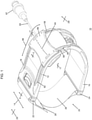
FIG. 1 is a perspective view of a radial compression band in accordance with the disclosure; -
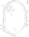
FIG. 2A is a side view of a radial compression band in accordance with the disclosure, with the bubble in an inflated state; -
FIG. 2B is a sectional side view of the radial compression band ofFIG. 2A , taken alongline 2B-2B ofFIG. 1 , with the bubble in a deflated state; -
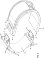
FIG. 3 is a perspective view of a partial radial band to illustrate the connection of the buckles; -
FIG. 4 is a view of a buckle being inserted into the radial band brace; -
FIG. 5 is a sectional view of the connection portion the buckle taken along line 5-5 ofFIG. 1 ; -
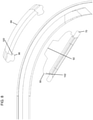
FIG. 6 is an exploded view of the radial band bubble assembly with the bubble in an inflated configuration; -
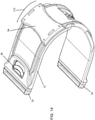
FIG. 7 is a partial perspective view of the radial compression band, without the bubble; -
FIG. 8 is sectional view taken along line 8-8 ofFIG. 7 ; -
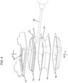
FIG. 9 is an exploded view of a partially constructed bubble assembly; -
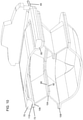
FIG. 10 is a sectional view of a fully constructed bubble assembly taken along line 10-10 ofFIG. 9 ; -
FIG. 11 is a sectional view taken along line 11-11 ofFIG. 1 ; -
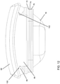
FIG. 12 is a view of the radial band bubble assembly by itself in a partially inflated mode; -
FIG. 13 is a view of the radial band bubble assembly in a fully inflated mode; -
FIGs. 14 and15 illustrate the radial band brace to demonstrate movement of the bubble assembly along the band brace; -
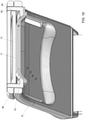
FIG. 16 is a perspective view of the radial band brace with bubble assembly installed, illustrating an optional pad; -
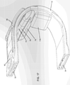
FIG. 17 is a perspective view of the radial band brace with bubble assembly installed, illustrating an optional positioning bubble; -
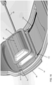
FIG. 18 is a partial perspective sectional view taken along line 11-11 ofFIG. 1 , but illustrating the bubble in a fully deflated state; -
FIG. 19 is a rear partial view illustrating a manner of securing the bubble assembly in position; -
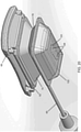
FIG. 20 is a view of an alternative bubble assembly that includes a hemostatic gel or coolant; -
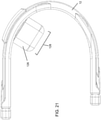
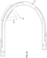
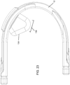
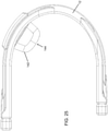
FIGs. 21-25 illustrate exemplary variations of bubble configurations; -
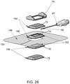
FIG. 26 is an exploded view that illustrates the process of constructing the bubble in manufacturing; -
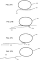
FIGs. 27A-27D illustrate removal of the covering to activate a hemostatic gel or other substance; -
FIG. 28 is a perspective view of a dual radial/ulnar compression band; and -
FIG. 29 is a side view of the dual radial/ulnar compression band ofFIG. 28 . - The system according to a preferred embodiment of the present disclosure comprises a substantially rigid partial cuff member, approximately in a U shape, is provided to receive the patient's wrist therein, with a securement strap that is attached to one end of the cuff and adapted to loop through the other end of the cuff, to secure the cuff to the wrist. One or more positionable inflation members are movable along a portion of the cuff to allow positioning of an inflation member over a puncture site. An inflation port may employ a standard luer lock connector to allow attachment of a syringe for inflation of the inflation member to provide pressure against the puncture site, for achieving non-occlusive hemostasis.
- Referring to
FIG. 1 , a perspective view of a radial compression band in accordance with the disclosure, theradial band assembly 10 comprises aradial band brace 12 that is approximately U-shaped and having awidth 14, which is adapted to fit over a patient's wrist where the wrist is received in the open central portion of the radial band brace. The band brace is slightly loaded so that the 'legs' of the U-shape are not exactly parallel to one another. In a particular embodiment, the radial band brace can be produced in different sizes, to accommodate different sized patient wrists. Typically a size is chosen that is just slightly larger than the patient's wrist. The band is suitably clear such that it is easily seen through, and may comprise of clear ABS, for example. The band can be provided with a color if desired. Acrylic may be used if rigidity is not an issue. The different sizes can be provided with slight color tints, each size being given a different color, to allow quick identification of which size the band is. The band is substantially rigid, with some amount of flexibility such that when the strap is tightened, the U-shaped legs will move towards each other somewhat to take up slack in the fit on the patient's wrist. Examples of suitable material to use in construction of the band includes PVC, ABS, Poly Urethane, or a blend thereof. - Referring to
FIG. 2A , a side view of the radial compression band with the bubble in an inflated state, it may be observed that according to the invention the U-shaped configuration is a slightly varied U, where oneleg 16 of the U portion is shorter than the other, the shorter leg being in the lower portion ofFIG. 2 , while theupper leg 18 is slightly longer, extending further to the left in the view ofFIG. 2 . - A
strap assembly 20 connects to the ends of the radial band brace, suitably by means of upper andlower buckles strap member 26 is received by the buckles, substantially permanently yet flexibly attached at one of the buckles,lower buckle 24, for example, and removably looped throughupper buckle 22. Hook andloop fasteners 28 are provided on the strap member to allow adjustment tightening of the tension on the strap and then securing the strap with the desired tension, allowing the band to be removably secured to the patient's wrist. An optional additional hook andloop material 28a may be provided on the band to secure any excess length of the strap, if desired. - Upper and
lower buckles FIGs 3-5 . - Referring to
FIG. 3 , a perspective view of a partial radial band, the connection of the buckles will be explained.Buckles tab portions slot portions FIGs. 16 and17 ). Consideringupper buckle 22, thetab 28 has a curved forward profile defining approximately an isosceles trapezoidal shape and has an upwardly projectinglatch portion 36 defined in the center region of the trapezoid. Thelatch portion 36 is biased to extend above the general plane of the tab in absence of downward force, but is sufficiently flexible to deform if pressed, and returns to the extended position when any such force is removed.Slots strap 26 therethrough, buckle 22 having the strap pass through in removable fashion, whilebuckle 24 has the strap looped through then the end of the strap is secured to a portion of the strap to permanently mount the buckle to the strap while still allowing some degree of movement for flexibility. The trapezoidal shape of the buckle extending tab portions provides a narrower width at the end of the tab distal from the attachment to the strap. - With reference to
FIG. 4 , a view of a buckle being inserted into the radial band brace, the curved narrower end of the trapezoidal shape allows easy insertion of the tab into the receivingslots latch portion 36. As the tab is further guided into the slot, eventually the latch portion will align with opening 40 defined in the band (opening 42 on the other end of the band) which relieves the compressing force on the latch, allowing the latch to return to its extended position and, operating to lock the buckle to theradial band brace 12. Removal of the device can be quickly accomplished by depressing the latch member 36 (38) which allows the buckle to be withdrawn from the slot, freeing the device from the patient's wrist. - The
latch portion 36 has an additional forwardly extending tab portion 37 (two such tabs being provided in the illustrated embodiment) that interacts with the lower face of theupper leg 18 around theopening 40, preventing the latch portion from riding up out of the opening via the top of the opening, which could prevent the removal of the latch when pulling on the strap when trying to removebuckle 22. - Referring to
FIG. 5 , a sectional view of the connection portion the buckle taken along line 5-5 ofFIG. 1 (with the strap removed), the interaction of thelatch 36 with theopening 40 can be observed when the tab is fully inserted into theslot 32.Latch 36 is fully extended upwardly, whereby theface 48 of the latch will interact with the edge of theopening 40 to prevent removal of the buckle. Upon depressing the latch in the direction ofarrow 50, the face of the latch is lowered to align with the opening of theslot 32, allowing the buckle to be pulled out of the slot in the direction ofarrow 52. The interaction oftab portion 37 with the bottom of the radial band brace at theopening 40 may also be observed inFIG. 5 , where the upper face of the tab seats against the lower face of the band brace adjacent of theopening 40. By this, the latch portion does not ride up over the walls of theopening 40, which could jam the latch against removal. - Referring again to
FIG. 1 andFIG. 2A , the device includes a radial band bubble assembly, which is slidingly movable along an extent of the band, the extent of movement allowed, illustrated byarrow 66, being defined byslots positions 60 to 62 in the illustrated embodiment. The bubble assembly may be moved to a desired position along the extent provided by the slots. On the inner side of the band, the bubble assembly comprises aninflatable bubble 64, which is in pneumatic communication viatube 65 with aconnector 67 that allows an inflation source to be connected to inflate or deflate the bubble.Connector 67 suitably comprises a luer lock. A valve (not shown) may be provided to allow inflation/deflation of the bubble as desired, while maintaining the state of inflation of the bubble in absence of inflation pressure or deflation suction. In use, inflation/deflation is provided by attachment of a syringe to theconnector 67 to allow a desired amount of inflation of thebubble 64. The insertion of the syringe operates the valve to allow inflation or deflation of the bubble. Removing the syringe causes the valve to close, maintaining the desired pressure. Pressure is applied by the inflated bubble in the direction ofarrow 158. - Now referring to
FIG. 6 , an exploded view of the radialband bubble assembly 54, which comprises, in top to bottom vertical order, atop bubble brace 68, abottom bubble brace 70 and an accordion bubble havingtop layer 72,middle layers bottom layer 78. The middle layers haveopen center portions bottom layers Bottom bubble brace 70 has acentral opening 84 defined in its substantially rectangular profile, and has upwardly extendingend members tab members 90 defined part way up the vertical height of the end members. A central upwardly projectingtab 92 is defined in the end members.Top bubble brace 68 has correspondingslots 94 which receivetabs 92 therein andtab members 96 oriented downwardly on the lower face of the brace, wherebytabs 92 fit intoslots 94 andtabs opening 84 provides a viewing window, and has on the patient facing side a slight recess 85 (visible inFIGs. 10 and11 ) so that a patient's skin is not pinched when sliding the bubble assembly. Thebottom portion 78 of the bubble provides a smooth contact surface with the patient's skin, without any seam lines or ridges, so no irritation or marking of the skin occurs as could happen if a ridge line were present. In the view ofFIG. 6 , the bubble portions are in positions when the bubble is inflated -
FIG. 7 is a partial perspective view of the radial compression band, taken together withFIG. 8 , a sectional view along line 8-8 ofFIG. 7 , to further illustrate the interaction and engagement of the top and bottom bubble braces 68 and 70, with the bubble removed for clarity of illustration.Tab 90 on the bottom brace has an angled surface andtab 96 on the top brace has a similar angled surface, such that when the two brace parts are pushed towards each other in the direction ofarrows 98, the two angled surfaces will ride on one another,tabs 96 will move outwardly as a result of flexing of the top brace, allowing the upwardly orientedsurface 100 of the top brace to mate with the downwardly orientedsurface 102 of the bottom brace, effectively securing the two brace portions together. Upwardly extendingend members slots tabs 96 extend down through the slots so that the assembled bubble brace can slide along the extent ofslots end members slots - Referring to
FIG. 9 , an exploded view of a partially constructed bubble assembly, andFIG. 10 , a sectional view of a fully constructed bubble assembly taken along line 10-10 ofFIG. 9 , when manufacturing the device, thebubble components middle layers openings Tube 65 is suitably inserted betweenlayers extra tab portion layers tube 65 at the point of entry into the bubble. The periphery ofbottom layer 78 is secured to the periphery oflayer 76 at joint 108, providing an assembled bubble with inflation tube. The dome like upper portion of thetop bubble layer 72 is moved into theopening 84 inbottom bubble brace 70 and the bubble is secured thereto at joint 110 alongperiphery 73. The size ofopening 84 is such that the top dome portion of the bubble fits therein. - The process of manufacturing the bubble may be understood with reference to
FIG. 26 , an exploded view of the bubble in the assembly process. The bubble layers are provided in sheets of material, with the bubble shape previously thermoformed in the sheets. In the preferred embodiment, each bubble section is formed to have the same concave shape.Layers sheet 146, such as a Teflon brand sheet, having anopening 148 is positioned between the twolayers Joint 104 is thus formed betweenlayers openings layer 72 is positioned on top oflayer 74, by nesting the bubble shape formation oflayer 74 on top of the concave bubble wall oflayer 74 and thetube 65 which is connected toluer lock 67, is positioned betweenlayers layers weld 154, to form joint 106, also securing the tube to the bubble.Layer 78 is positioned belowlayer 76 by nesting the bubble shape oflayer 78 with the bubble shape oflayer 76 and joint 108 betweenlayer weld 156, again in the peripheral shape of the ultimate bubble shape desired. The polytetrafluoroethylene (PTFE)sheet 146 is employed to properly accomplish the welding, prevents the peripheries oflayers slit 150 formed from the hole to the outer edge of the PTFE sheet, so that once the bubbles are fully formed, the PTFE sheet may then be pulled out, the slit allowing the sheet to be removed from around the bubble. While a PTFE sheet is shown in the particular embodiment, other materials can be used for the sheet, such as metal, or any other material that will protect against the unintended welding of the peripheries oflayers FIG. 26 for illustration, in production, multiple bubbles may be formed at a time, such as 4 or more bubbles formed spaced apart in a sheet of material, with a corresponding configuration of PTFE sheet havingseparate openings 148 corresponding to the configuration of the separate bubbles. The PTFE holes 148 where the bubbles are have correspondingslits 150 from the holes to the outer edge of the PTFE sheet. This way the bubbles are fully formed while still in the sheet form, the PTFE is then pulled away, then the multiple bubbles are die cut out of the stack of the 4 layers all at once or in some sequence of cutting operations. Once die cut to a separate bubble, the bubble may then be adhered tobottom bubble brace 70, either by welding or use of adhesive. The bubble layers are nested together so that the uninflated bubble will assume a resting shape with the layers retracted as inFIG. 18 , to be substantially pulled away from a patient's skin when deflated. Suitable material to use in forming the bubble includes PVC or Poly Urethane. - Since the
tube 65 inserts above the lower bubble face, when inflated, the tube is lifted above the surface of the patient's skin. Alternatively, the tube can pass through thetop bubble brace 68, or throughslots -
FIG. 11 is a sectional view taken along line 11-11 ofFIG. 1 , illustrating the fully assembled bubble assembly mounted to the band brace, with the bubble in a fully inflated configuration. Referring toFIG. 18 , the configuration of the bubble when deflated can be observed, wherein the various layers of the bubble nest together to allow the bubble to retract within itself, so that the surface of theskin side layer 78 of the bubble is pulled away from the patient's skin and the clot. Also, this configuration assures that no sharp edges are pressing against the patient. -
FIGs. 12 and13 show the bubble (with the band removed for illustration purposes) in a partially inflated mode (FIG. 12 ) wherebubble layer 78 has expanded, but substantially the other layers have not yet expanded outwardly, and a fully inflated mode (FIG. 13 ).FIG. 18 is a partial perspective sectional view illustrating the bubble in a fully deflated state, wherein the bubble is fully collapsed upward into theopening 84 defined in thebottom bubble brace 70. In this fully deflated mode, the central portion of the bubble is pulled away from the patient's body by the collapsing into theopening 84. Thevarious layers -
FIG. 2B , a sectional side view of the radial compression band ofFIG. 2A , taken alongline 2B-2B ofFIG. 1 , with the bubble in an deflated state, further illustrates the retraction of the bubble into theopening 84. -
FIGs. 14 and15 demonstrate movement of the bubble assembly along the band brace, where the bubble assembly has moved up along the brace in the direction ofarrow 112. -
FIG. 16 is a perspective view of the radial band brace with bubble assembly installed, illustrating an radial band pad 114 (also visible inFIG. 2B ) that is installed at an inner portion of the radial band brace to provide added comfort to the patient and stability to the band. The pad may comprise a foam, for example, or a silicone, or more preferably a low durometer TPE, for example with a 3A shore hardness, which provides a jelly like feel and also provides gripping of the patient's arm, without pulling on hair on the arm. Thepad 114 assists in providing pressure in the direction of arrow 160 against the patient's arm. -
FIG. 17 is a perspective view of the radial band brace with bubble assembly installed, illustrating anoptional positioning bubble 116 that may be inflated to assist with positional adjustment on a patient's wrist, which can help in accommodating different wrist sizes and shapes. - Alternative configurations can employ multiple bubbles and a valve or valves to allow selection of which bubbles to inflate, allowing a variety of pressure application choices.
- The top bubble brace, bubble layers and the radial band brace (at least in the area the bubble assembly slides over) are suitably made of clear or transparent material to allow unobstructed viewing of the patient's arm through the material. The material can be clear or translucent or even opaque so long as sufficient detail of the site on the patient's arm is visible through the layers to allow accurate positioning. This enables the medical personnel operating the band to precisely position the bubble over the desired spot on the patient's arm to ensure that pressure from the inflated bubble is applied to the proper location. In the configuration illustrated, only 4 layers of material are required to view through, the
top bubble brace 68, theradial band brace 12, thetop bubble layer 72 and thebottom bubble layer 78. This number could be reduced by, for example, providing a cut out viewing region in the center of theband brace 12 and/or by providing a cut out viewing region in thetop bubble brace 68. The top bubble brace may have anindicator line 69 defined therein, to assist with aligning the bubble over the desired pressure point. Alternatively the indicator line may be on the bubble itself, such as on the bottom layer of the bubble. The medical personnel can use the indicator line to position the bubble over the wound site. The indicator line may be of a specific color, such as green, for example. Alternatively, thebottom bubble portion 78 may have such a line 69' (visible inFIG. 19 ). Since the various layers are clear or translucent, the line is clearly visible from the top surface of the band when it is positioned on the patient. The bubble layers and band in the bubble region can also be provided with a color if desired. -
FIG. 19 is a rear partial view illustrating a manner of securing the bubble assembly in position. In this configuration, a band ofserrations 118 is provided on an inner surface of theband 12 and corresponding projections 120 (indicated inFIG. 6 ) are provided on counterpart surfaces ofbottom bubble brace 70, wherein on inflation of the bubble, the interaction with the bubble and the patient's arm will press theprojections 120 into engagement with theserrations 118, to cause the bubble to resist against further sliding, so that the position of the bubble is maintained. An alternative way to secure the bubble without serrations may be understood by reference toFIG. 11 , wherein on inflation of the bubble, theupper bubble portion 72 expands such that theupper surface 71 of thebubble portion 72 presses against the inner surface of thecentral portion 13 of theband 12, and the frictional engagement of the bubble and the band will sufficiently secure the bubble assembly against unintended movement. - In another embodiment, visible in
FIG. 20 , a view of an alternative bubble assembly that includes a hemostatic gel or coolant, ahemostatic gel 123 may be provided in areceptacle 122 at the bottom bubble layer. Asterile sealing layer 124 may be provided over the gel receptacle, which is then removed just prior to placing the band on the patient, whereby the gel can be dispensed throughopenings 126 by pressure provided by the inflating bubble exerted on the rear of thereceptacle 122. - In still another embodiment,
receptacle 122 can contain a cooling element to provide cooling to help retract the artery. The device may then be stored in a refrigerator/freezer prior to use. A combination of cooling element and hemostatic gel may be provided. -
FIG. 27A-D illustrates a manner of removinglayer 124, wherein thelayer 124 initially covers thegel 123, and comprises a folded over portion, and is pulled fromend 121 in the direction of arrow 125 (FIG. 27A ). The end of thelayer 124 distal from the pulled portion rolls over and begins to peel away from the gel. As the layer is further pulled (FIGs. 27B and 27C ), more of the gel is exposed until finally (FIG. 27D ), thelayer 124 is completely pulled away, exposing the gel fully. - Referring to
FIG. 28 , a perspective view of a dual radial and ulnar compression band in accordance with the disclosure, andFIG. 29 , a side view of the dual radial and ulnar compression band ofFIG. 28 , the radial/ulnar band assembly 10' corresponds somewhat to the construction and operation of the radial band device described above and comprises many corresponding features, including a band brace 12' that is approximately U-shaped and having a width 14', which is adapted to fit over a patient's wrist where the wrist is received in the open central portion of the radial band brace. The band brace is slightly loaded so that the 'legs' of the U-shape are not exactly parallel to one another. In a particular embodiment, the band brace can be produced in different sizes, to accommodate different sized patient wrists. As with the radial band discussed above, the band is suitably clear such that it is easily seen through, and may comprise of clear ABS, for example. The band can be provided with a color if desired. Acrylic may be used if rigidity is not an issue. The different sizes can be provided with slight color tints, each size being given a different color, to allow quick identification of which size the band is. The band is substantially rigid, with some amount of flexibility such that when the strap is tightened, the U-shaped legs will move towards each other somewhat to take up slack in the fit on the patient's wrist. Examples of suitable material to use in construction of the band includes PVC, ABS, Poly Urethane, or a blend thereof. - A strap assembly 20' connects to the ends of the band brace, suitably by means of upper and lower buckles 22'and 24', which removably connect to the band brace at the 'ends' of the U-shape of the band brace. A strap member 26' is received by the buckles, substantially permanently yet flexibly attached at one of the buckles, lower buckle 24', for example, and removably looped through upper buckle 22'. Hook and loop fasteners 28' are provided on the strap member to allow adjustment tightening of the tension on the strap and then securing the strap with the desired tension, allowing the band to be removably secured to the patient's wrist. A band pad 114' may be installed at an inner portion of the radial band brace to provide added comfort to the patient and stability to the band and to assist in providing pressure against the patient's arm.
- The device 10' includes a radial band bubble assembly 64' and an ulnar
band bubble assembly 170, the bubble assemblies being slidingly movable along an extent of the band, being defined by slots which extend from the top to the underside portion of the band from positions in the illustrated embodiment. The bubble assemblies may be moved to desired positions along the extent provided by the slots, suitably to be positioned over the radial and ulnar arteries, or puncture sites made to access these arteries. On the inner side of the band, the bubble assemblies comprisesinflatable bubbles 64' and 170, being of corresponding construction to thebubble 64 described above. The bubbles are in pneumatic communication viatubes 65' and 172 withconnectors Connectors 67' and 174 suitably comprise luer locks. Valves (not shown) may be provided to allow inflation/deflation of the bubbles as desired, while maintaining the state of inflation of the bubbles in absence of inflation pressure or deflation suction. In use, inflation/deflation is provided by attachment of a syringe to the connectors 67' and/or 174 to allow a desired amount of inflation of thebubble 64' or 170. The insertion of the syringe operates the valve to allow inflation or deflation of the bubbles. Removing the syringe causes the valve to close, maintaining the desired pressure. The bubbles may be configured to be inflated separately as in the illustrations, or inflated together, as desired. - The shape of the bubble portion that directly contact's the patient's arm for either the single or dual bubble versions may be modified for different pressure application profiles. Considering
FIGs. 21-25 , which are side views of single bubble bands without the strap installed, the bubbles can have, for example, a square profile bubble 126 (FIG. 21 ) for a moreflat contact surface 128, atriangular profile bubble 130 providing a narrower contact surface 132 (FIG. 22 ), a modifiedsquare profile 134 with one side longer to provide a wider contact region 136 (FIG. 23 ), acurved side profile 138 providing a wider more curved contact profile 140 (FIG. 24 ), and a curved edgerectangular shape 142 providing yet another curvedcontact surface profile 144. Other shapes may of course be employed to provide desired contact pressure profiles against the patient's arm. The various shapes of the bubbles allow targeted application of pressure to the wrist site along an axis of the bubble, and can be line, oval, rectangular or other shape pressure application profiles, depending on the bubble configuration. - Bubbles having greater length along the direction of the arm's length can be provided for use in applications where a longer incision has been made in the patient, so that pressure is applied over a greater length.
- In use of the device, the band portion is slid over the patient's wrist and the strap portions are snapped in place. The bubble or bubbles are approximately positioned over the insertion site(s) of the catheter(s), and the strap is tightened. A syringe is attached to the luer lock of one of the bubbles (or a pair of syringes may be used in the dual bubble version, or the dual bubbles may be connected to use the same inflation source simultaneously). The bubble assembly (or assemblies) is slid to be in an optimal position, with use of the optional guide mark if desired, and the bubble is inflated, locking the slide against unintended movement. The locking can be accomplished by inflation of the bubble causing a portion of the bubble to press against the brace. The individual catheter is removed. If bleeding starts immediately, the bubble is inflated further. If no bleeding is observed, pressure is released until just the point that bleeding starts, whereupon 2 cc of air (or other fluid) are added, the syringe is removed from the luer lock, and after 30-60 minutes, as determined by the medical personnel, then 2 cc are removed from the bubble every 5 minutes. Once it is determined that hemostatis has been achieved, the bubble is deflated and slid away from the site. The sideward movement of the bubble reduces the chance of tearing the clotted seal on the artery away as opposed to pulling directly upwardly as with prior art solutions.
- The disclosed band has numerous benefits over prior solutions. The attachment of the band to the arm is separate from final positioning of the bubble over the site. The slidable bubble assembly allows precise positioning of the bubble for maximum effect. The bubble is typically smaller than prior art devices, and can provide a pinpoint focus of pressure. The pressure applied by the inflated bubble pushes off axis, as indicated by
arrow 158 inFIG. 2A , pushing the artery directly into the patient's bone, not merely pushing the artery in a direction that might not be normal to the bone, which would be less effective. The angle at which the pressure is applied can be varied in accordance with the disclosure. The number of surfaces through which the site is viewed is reduced over prior solutions. When deflated, the bubble retracts into itself and forms a concavity relative to the skin to keep the bubble away from contact with the skin. Unlike prior devices, the band and bubble location will not substantially rotate when the bubble is inflated. The device is easily put onto a patient's wrist by sliding the band onto the wrist from the side, then the strap may be clipped in and tightened to secure the band on the patient. The patient's wrist need not be lifted to install the band. While traditional devices tend to constrict the patient's entire wrist, almost acting like a tourniquet, the relatively rigid material of the band of the present device instead acts as a hinge, keeping pressure from being applied to the entire wrist, allowing specific pressure application where needed by the bubble, which mimics pressure applied by a finger by medical personnel, as is done when no radial band is available. The bubble in the illustrated configurations is suitably inflatable to 0,69 bar (10 psi), which is more than sufficient. While the illustrated inflation medium is air, fluid or other gases may be employed to inflate the bubble. The bubble can be provided with a slow rate leak, such that it will slowly deflated over time on its own without intervention, so that after a sufficient time to allow hemostasis, the bubble pressure is released. The skin contact surface of the bubble can be provided with a medication or other substance to assist with the function. - The illustrated application of the device is with radial/ulnar artery procedures, but other uses are possible, such as with stopping bleeding in dialysis procedures, for example.
- While plural preferred embodiments of the technology have been shown and described, it will be apparent to those skilled in the art that many changes and modifications may be made without departing from the broader aspects.
Claims (13)
- A hemostasis device, comprising:an attachment device (10) for securing the hemostasis device to a patient, said attachment device comprising a substantially rigid partial cuff member (12) that has substantially a U shape with two respective legs (16, 18) and is adapted to fit over a patient's wrist and has a top portion with a first position (60) therein and an underside portion with a second position (62) therein;a positionable inflatable pressure application device (54) for positioning over a site independent of securing of the attachment device,said positionable inflatable pressure application device (54) being movable along an extent of the partial cuff member (12) and further comprising on an inner side of said partial cuff member (12) an inflatable member (64) adapted to press against the patient when inflated, wherein said extent is from said first position (60) to said second position (62);the device being characterized in that,- one (16) of said legs (16, 18) is shorter than the other leg that is thusly the longer leg (18);- said second position (62) is located at the longer leg (18); and- the device further comprises a stability and comfort radial band pad (114) installed on said inner side along the shorter leg (16).
- The hemostasis device according to claim 1, wherein said attachment device (10) further comprises a strap member (26) that connects, by means of removable buckles (22, 24), to the ends of the partial cuff member (12), for enabling the hemostasis device to be secured to the patient's wrist.
- The hemostasis device according to claim 1 wherein said inflatable member (64) includes a substantially clear viewing portion for enabling viewing of the position on the patient where said inflatable member presses when inflated.
- The hemostasis device according to claim 1, said pressure application device further comprising a receptacle (122) for holding a substance wherein the substance is dispensed to the patient by pressure provided by the pressure application device (54).
- The hemostasis device according to claim 4, wherein said substance comprises a hemostatic substance (123) and / or cooling element.
- The hemostasis device according to claim 4, wherein said receptacle (122) comprises a removable sterile sealing layer (124).
- The hemostasis device according to claim 1, wherein the positionable pressure application device comprises a first and a second pressure application device for pressing against a radial and an ulnar puncture site respectively.
- The hemostasis device according to claim 1, further comprising a locking device for substantially locking said positionable inflatable member (64) in location when positioned to a desired location.
- The hemostasis device according to claim 1, further comprising an inflation member with a luer lock attachment (67) for connection to a pressure source, for allowing inflation/deflation of the inflatable member (64).
- The hemostasis device according to claim 1, further comprising a second positionable inflatable member adapted to slide along a portion of the partial cuff member (12) for positioning of the second positionable inflatable member at a second site, and adapted to press against the patient when inflated.
- The hemostasis device according to claim 1, wherein the stability and comfort radial band pad (114) comprises a foam or a silicone.
- The hemostasis device according to claim 1, wherein the two legs (16, 18) are not parallel to one another.
- The hemostasis device according to claim 1, wherein the partial cuff member (12) comprises two slots (56, 58) which extend from the top to the underside portion of the band from the first position (60) to the second position (62), said slots defining said extent.
Applications Claiming Priority (3)
| Application Number | Priority Date | Filing Date | Title |
|---|---|---|---|
| US201662313591P | 2016-03-25 | 2016-03-25 | |
| US15/255,017 US10588638B2 (en) | 2016-03-25 | 2016-09-01 | Radial compression band |
| PCT/US2017/020992 WO2017165108A1 (en) | 2016-03-25 | 2017-03-06 | Radial and ulnar compression band |
Publications (3)
| Publication Number | Publication Date |
|---|---|
| EP3432809A1 EP3432809A1 (en) | 2019-01-30 |
| EP3432809A4 EP3432809A4 (en) | 2019-10-30 |
| EP3432809B1 true EP3432809B1 (en) | 2022-02-16 |
Family
ID=70804217
Family Applications (1)
| Application Number | Title | Priority Date | Filing Date |
|---|---|---|---|
| EP17770811.2A Not-in-force EP3432809B1 (en) | 2016-03-25 | 2017-03-06 | Radial and ulnar compression band |
Country Status (8)
| Country | Link |
|---|---|
| US (1) | US11432824B2 (en) |
| EP (1) | EP3432809B1 (en) |
| JP (1) | JP6941114B2 (en) |
| KR (1) | KR102359636B1 (en) |
| CN (1) | CN109069163B (en) |
| AU (1) | AU2017237806B2 (en) |
| MX (1) | MX2018010409A (en) |
| WO (1) | WO2017165108A1 (en) |
Cited By (1)
| Publication number | Priority date | Publication date | Assignee | Title |
|---|---|---|---|---|
| EP3979924B1 (en) * | 2019-06-06 | 2025-05-07 | Les Entreprises Nanostent Inc. | Apparatus for adjustable and simultaneous multiple vessel compression |
Families Citing this family (23)
| Publication number | Priority date | Publication date | Assignee | Title |
|---|---|---|---|---|
| AU2017299466B2 (en) | 2016-07-18 | 2022-07-14 | Merit Medical Systems, Inc. | Inflatable radial artery compression device |
| JP7181280B2 (en) * | 2018-03-30 | 2022-11-30 | テルモ株式会社 | hemostatic device |
| JP7168338B2 (en) * | 2018-03-30 | 2022-11-09 | テルモ株式会社 | hemostatic device |
| WO2019199969A1 (en) | 2018-04-11 | 2019-10-17 | Merit Medical Systems, Inc. | Inflatable compression device |
| EP3815629B1 (en) * | 2018-07-20 | 2025-09-03 | TERUMO Kabushiki Kaisha | Compression device |
| US11446040B2 (en) * | 2018-08-06 | 2022-09-20 | Medtronic Vascular, Inc. | Ulnar compression device |
| EP4578408A3 (en) * | 2019-03-01 | 2025-08-20 | Terumo Kabushiki Kaisha | Methods of constructing hemostasis devices with folded balloon assemblies |
| US20200289129A1 (en) * | 2019-03-14 | 2020-09-17 | Medtronic Vascular, Inc. | Tissue compression device |
| US11364053B2 (en) | 2019-06-14 | 2022-06-21 | Terumo Medical Corporation | Tibiopedal vascular closure band |
| US20210052430A1 (en) * | 2019-08-22 | 2021-02-25 | Paula Riley | Apparatus for hands free application of compression to a wound site |
| US11730487B2 (en) * | 2019-08-29 | 2023-08-22 | Mohammad Reza Rajebi | Vascular hemostasis system |
| US12484911B2 (en) * | 2020-08-13 | 2025-12-02 | Merit Medical Systems, Inc. | Inflatable radial artery compression device with cinching wristband and method of use |
| CN112401965A (en) * | 2020-12-04 | 2021-02-26 | 吉林大学第一医院 | ICU emergency nursing is with internal hemorrhage patient structure of stanching fast |
| JP7523377B2 (en) * | 2021-02-09 | 2024-07-26 | テルモ株式会社 | Hemostatic devices |
| US12426864B2 (en) | 2021-06-18 | 2025-09-30 | Merit Medical Systems, Inc. | Hemostasis devices and methods of use |
| US12402889B2 (en) * | 2021-08-24 | 2025-09-02 | Sandeep Kumar Goyal | Hemostasis aiding device |
| WO2023053883A1 (en) * | 2021-09-28 | 2023-04-06 | テルモ株式会社 | Compression device and method for adjusting compression position |
| CN114521951B (en) * | 2021-12-31 | 2024-07-05 | 常州华森医疗器械股份有限公司 | Sternum plate convenient to disassemble |
| CN114569188B (en) * | 2022-03-10 | 2023-07-25 | 郑州大学第一附属医院 | A nursing device for assisting blood purification |
| KR102583912B1 (en) | 2022-10-13 | 2023-09-27 | 주식회사 에어스메디컬 | Apparatus for compressing body parts |
| CN115813481B (en) * | 2023-02-15 | 2023-05-16 | 中南大学湘雅医院 | Cardiovascular intervention puncture auxiliary device |
| KR102649811B1 (en) * | 2023-12-18 | 2024-03-20 | 이정현 | Compression hemostasis band device capable of detecting deviation of hemostasis area |
| KR102752828B1 (en) | 2024-02-29 | 2025-01-09 | 이정현 | Hemostatic compression band with automatic decompression adjustment based on pressure monitoring and timer |
Family Cites Families (30)
| Publication number | Priority date | Publication date | Assignee | Title |
|---|---|---|---|---|
| US4224945A (en) * | 1978-08-30 | 1980-09-30 | Jonathan Cohen | Inflatable expansible surgical pressure dressing |
| JP3129107B2 (en) * | 1994-09-05 | 2001-01-29 | 日本ゼオン株式会社 | Compression hemostasis device |
| US5709647A (en) * | 1995-08-01 | 1998-01-20 | Ferberdent International Inc. | Acupressure device |
| US5728120A (en) * | 1996-05-06 | 1998-03-17 | Shani; Jacob | Wrist clamp for arterial compression |
| WO1998046144A1 (en) * | 1997-04-14 | 1998-10-22 | Advanced Closure Systems, Inc. | Feedback controlled disposable hemostasis device |
| SE9701935D0 (en) | 1997-05-23 | 1997-05-23 | Radi Medical Systems | Medical device |
| US5916209A (en) | 1997-12-24 | 1999-06-29 | Mick; Matthew J. | Coronary catheters for use in a transradial catheterization |
| AU3306699A (en) * | 1998-02-27 | 1999-09-15 | John D. Cochrane III | Male urinary incontinence control device |
| DE19902036C1 (en) | 1999-01-20 | 2000-03-16 | Storz Karl Gmbh & Co Kg | Device to hold trocar tube aligned in various spaces; is designed to fasten trocar tube in different adjustable in situ positions on patient |
| ATE431723T1 (en) * | 2001-09-20 | 2009-06-15 | Radi Medical Systems | ADJUSTABLE PRESSURE DEVICE FOR THE RADIAL ARTERY |
| US8936588B2 (en) | 2001-09-21 | 2015-01-20 | Fred Herz Patents, LLC | Device and method for prevention and treatment of deep venous thrombosis |
| DE60328343D1 (en) | 2002-07-15 | 2009-08-27 | Terumo Corp | Hemostatic device with inflatable balloon |
| JP4398747B2 (en) * | 2004-02-05 | 2010-01-13 | テルモ株式会社 | Hemostatic device |
| CN201029906Y (en) * | 2007-04-25 | 2008-03-05 | 河北医科大学第二医院 | radial artery hemostat |
| EP2459079B1 (en) | 2009-07-31 | 2014-05-07 | Perouse Medical | Compressive hemostatic device |
| US8784844B2 (en) | 2009-09-30 | 2014-07-22 | Lonza Ltd. | Arabinogalactan for enhancing the adaptive immune response |
| US20140012120A1 (en) | 2012-03-06 | 2014-01-09 | Accumed Radial Systems, Llc | Hemostasis sensor and method of use thereof |
| US20130310628A1 (en) | 2012-05-15 | 2013-11-21 | Ernest C. Chisena | Orthopaedic device and method of use for treating bone fractures |
| USD705429S1 (en) | 2012-08-29 | 2014-05-20 | Merit Medical Systems, Inc. | Medical compression bandage |
| USD705428S1 (en) | 2012-08-29 | 2014-05-20 | Merit Medical Systems, Inc. | Medical compression bandage |
| WO2014081970A1 (en) * | 2012-11-21 | 2014-05-30 | Medical Ingenuities, LLC | Radial compression hemostasis band with doppler confirming vascular patency |
| US9427239B2 (en) | 2013-07-12 | 2016-08-30 | Semier Technologies, Inc. | Apparatus and method of use for an adjustable radial and ulnar compression wristband |
| JP2015066032A (en) | 2013-09-27 | 2015-04-13 | テルモ株式会社 | Hemostatic band |
| US9955978B2 (en) | 2013-10-25 | 2018-05-01 | Medtronic Vascular, Inc. | Tissue compression device with multi-chamber bladder |
| JP2015083778A (en) | 2013-10-25 | 2015-04-30 | 日立オートモティブシステムズ株式会社 | Internal combustion engine control device |
| WO2015122233A1 (en) | 2014-02-17 | 2015-08-20 | テルモ株式会社 | Hemostasis tool |
| US20150327870A1 (en) * | 2014-05-15 | 2015-11-19 | Abbott Cardiovascular Systems, Inc. | Methods, systems, and devices for applying target force to a radial access puncture site |
| WO2016112342A1 (en) * | 2015-01-09 | 2016-07-14 | Hemcon Medical Technologies, Inc. | Percutaneous vascular injury treatment systems and methods |
| WO2017039005A1 (en) * | 2015-09-03 | 2017-03-09 | テルモ株式会社 | Hemostatic instrument |
| CN205054331U (en) * | 2015-10-14 | 2016-03-02 | 杭州山友医疗器械有限公司 | Arteria constricting hemostat |
-
2017
- 2017-03-06 CN CN201780020033.4A patent/CN109069163B/en active Active
- 2017-03-06 EP EP17770811.2A patent/EP3432809B1/en not_active Not-in-force
- 2017-03-06 AU AU2017237806A patent/AU2017237806B2/en not_active Ceased
- 2017-03-06 JP JP2018550418A patent/JP6941114B2/en active Active
- 2017-03-06 MX MX2018010409A patent/MX2018010409A/en unknown
- 2017-03-06 KR KR1020187027167A patent/KR102359636B1/en active Active
- 2017-03-06 WO PCT/US2017/020992 patent/WO2017165108A1/en not_active Ceased
- 2017-03-06 US US16/084,528 patent/US11432824B2/en active Active
Cited By (1)
| Publication number | Priority date | Publication date | Assignee | Title |
|---|---|---|---|---|
| EP3979924B1 (en) * | 2019-06-06 | 2025-05-07 | Les Entreprises Nanostent Inc. | Apparatus for adjustable and simultaneous multiple vessel compression |
Also Published As
| Publication number | Publication date |
|---|---|
| US20190167273A1 (en) | 2019-06-06 |
| EP3432809A4 (en) | 2019-10-30 |
| CA3015366A1 (en) | 2017-09-28 |
| CN109069163A (en) | 2018-12-21 |
| CN109069163B (en) | 2022-10-11 |
| KR102359636B1 (en) | 2022-02-09 |
| AU2017237806B2 (en) | 2021-09-23 |
| MX2018010409A (en) | 2019-03-06 |
| JP2019515711A (en) | 2019-06-13 |
| EP3432809A1 (en) | 2019-01-30 |
| JP6941114B2 (en) | 2021-09-29 |
| AU2017237806A1 (en) | 2018-09-06 |
| WO2017165108A1 (en) | 2017-09-28 |
| US11432824B2 (en) | 2022-09-06 |
| KR20180126484A (en) | 2018-11-27 |
Similar Documents
| Publication | Publication Date | Title |
|---|---|---|
| AU2017237806B2 (en) | Radial and ulnar compression band | |
| US10588638B2 (en) | Radial compression band | |
| US11439408B2 (en) | Hemostatic device | |
| EP1487355B1 (en) | Device and method for compressing wounds | |
| US5584853A (en) | Tourniquet cuff apparatus | |
| US5968072A (en) | Method and apparatus for cold compression treatment of wounds | |
| CN108024817B (en) | hemostatic device | |
| US20180310944A1 (en) | Apparatus for an adjustable radial and ulnar compression wristband | |
| JP2000515773A (en) | Wound closure hemostasis device | |
| CN112218590A (en) | Compression apparatus and compression method | |
| KR20210025674A (en) | Suction closure device and method | |
| US20250331833A1 (en) | Hemostasis devices and methods of use | |
| JPH05154160A (en) | Multipoint pressing and blood stopping device | |
| CA3015366C (en) | Radial and ulnar compression band | |
| AU2007201004B2 (en) | Device and method for compressing wounds |
Legal Events
| Date | Code | Title | Description |
|---|---|---|---|
| STAA | Information on the status of an ep patent application or granted ep patent |
Free format text: STATUS: THE INTERNATIONAL PUBLICATION HAS BEEN MADE |
|
| PUAI | Public reference made under article 153(3) epc to a published international application that has entered the european phase |
Free format text: ORIGINAL CODE: 0009012 |
|
| STAA | Information on the status of an ep patent application or granted ep patent |
Free format text: STATUS: REQUEST FOR EXAMINATION WAS MADE |
|
| 17P | Request for examination filed |
Effective date: 20181017 |
|
| AK | Designated contracting states |
Kind code of ref document: A1 Designated state(s): AL AT BE BG CH CY CZ DE DK EE ES FI FR GB GR HR HU IE IS IT LI LT LU LV MC MK MT NL NO PL PT RO RS SE SI SK SM TR |
|
| AX | Request for extension of the european patent |
Extension state: BA ME |
|
| DAV | Request for validation of the european patent (deleted) | ||
| DAX | Request for extension of the european patent (deleted) | ||
| A4 | Supplementary search report drawn up and despatched |
Effective date: 20190927 |
|
| RIC1 | Information provided on ipc code assigned before grant |
Ipc: A61B 17/132 20060101ALI20190923BHEP Ipc: A61B 17/135 20060101AFI20190923BHEP |
|
| GRAJ | Information related to disapproval of communication of intention to grant by the applicant or resumption of examination proceedings by the epo deleted |
Free format text: ORIGINAL CODE: EPIDOSDIGR1 |
|
| STAA | Information on the status of an ep patent application or granted ep patent |
Free format text: STATUS: GRANT OF PATENT IS INTENDED |
|
| GRAP | Despatch of communication of intention to grant a patent |
Free format text: ORIGINAL CODE: EPIDOSNIGR1 |
|
| INTG | Intention to grant announced |
Effective date: 20210929 |
|
| GRAS | Grant fee paid |
Free format text: ORIGINAL CODE: EPIDOSNIGR3 |
|
| GRAA | (expected) grant |
Free format text: ORIGINAL CODE: 0009210 |
|
| STAA | Information on the status of an ep patent application or granted ep patent |
Free format text: STATUS: THE PATENT HAS BEEN GRANTED |
|
| AK | Designated contracting states |
Kind code of ref document: B1 Designated state(s): AL AT BE BG CH CY CZ DE DK EE ES FI FR GB GR HR HU IE IS IT LI LT LU LV MC MK MT NL NO PL PT RO RS SE SI SK SM TR |
|
| REG | Reference to a national code |
Ref country code: GB Ref legal event code: FG4D |
|
| REG | Reference to a national code |
Ref country code: CH Ref legal event code: EP |
|
| REG | Reference to a national code |
Ref country code: DE Ref legal event code: R096 Ref document number: 602017053453 Country of ref document: DE |
|
| REG | Reference to a national code |
Ref country code: AT Ref legal event code: REF Ref document number: 1468408 Country of ref document: AT Kind code of ref document: T Effective date: 20220315 |
|
| REG | Reference to a national code |
Ref country code: IE Ref legal event code: FG4D |
|
| REG | Reference to a national code |
Ref country code: LT Ref legal event code: MG9D |
|
| REG | Reference to a national code |
Ref country code: NL Ref legal event code: MP Effective date: 20220216 |
|
| REG | Reference to a national code |
Ref country code: AT Ref legal event code: MK05 Ref document number: 1468408 Country of ref document: AT Kind code of ref document: T Effective date: 20220216 |
|
| PG25 | Lapsed in a contracting state [announced via postgrant information from national office to epo] |
Ref country code: SE Free format text: LAPSE BECAUSE OF FAILURE TO SUBMIT A TRANSLATION OF THE DESCRIPTION OR TO PAY THE FEE WITHIN THE PRESCRIBED TIME-LIMIT Effective date: 20220216 Ref country code: RS Free format text: LAPSE BECAUSE OF FAILURE TO SUBMIT A TRANSLATION OF THE DESCRIPTION OR TO PAY THE FEE WITHIN THE PRESCRIBED TIME-LIMIT Effective date: 20220216 Ref country code: PT Free format text: LAPSE BECAUSE OF FAILURE TO SUBMIT A TRANSLATION OF THE DESCRIPTION OR TO PAY THE FEE WITHIN THE PRESCRIBED TIME-LIMIT Effective date: 20220616 Ref country code: NO Free format text: LAPSE BECAUSE OF FAILURE TO SUBMIT A TRANSLATION OF THE DESCRIPTION OR TO PAY THE FEE WITHIN THE PRESCRIBED TIME-LIMIT Effective date: 20220516 Ref country code: NL Free format text: LAPSE BECAUSE OF FAILURE TO SUBMIT A TRANSLATION OF THE DESCRIPTION OR TO PAY THE FEE WITHIN THE PRESCRIBED TIME-LIMIT Effective date: 20220216 Ref country code: LT Free format text: LAPSE BECAUSE OF FAILURE TO SUBMIT A TRANSLATION OF THE DESCRIPTION OR TO PAY THE FEE WITHIN THE PRESCRIBED TIME-LIMIT Effective date: 20220216 Ref country code: HR Free format text: LAPSE BECAUSE OF FAILURE TO SUBMIT A TRANSLATION OF THE DESCRIPTION OR TO PAY THE FEE WITHIN THE PRESCRIBED TIME-LIMIT Effective date: 20220216 Ref country code: ES Free format text: LAPSE BECAUSE OF FAILURE TO SUBMIT A TRANSLATION OF THE DESCRIPTION OR TO PAY THE FEE WITHIN THE PRESCRIBED TIME-LIMIT Effective date: 20220216 Ref country code: BG Free format text: LAPSE BECAUSE OF FAILURE TO SUBMIT A TRANSLATION OF THE DESCRIPTION OR TO PAY THE FEE WITHIN THE PRESCRIBED TIME-LIMIT Effective date: 20220516 |
|
| PG25 | Lapsed in a contracting state [announced via postgrant information from national office to epo] |
Ref country code: PL Free format text: LAPSE BECAUSE OF FAILURE TO SUBMIT A TRANSLATION OF THE DESCRIPTION OR TO PAY THE FEE WITHIN THE PRESCRIBED TIME-LIMIT Effective date: 20220216 Ref country code: LV Free format text: LAPSE BECAUSE OF FAILURE TO SUBMIT A TRANSLATION OF THE DESCRIPTION OR TO PAY THE FEE WITHIN THE PRESCRIBED TIME-LIMIT Effective date: 20220216 Ref country code: GR Free format text: LAPSE BECAUSE OF FAILURE TO SUBMIT A TRANSLATION OF THE DESCRIPTION OR TO PAY THE FEE WITHIN THE PRESCRIBED TIME-LIMIT Effective date: 20220517 Ref country code: FI Free format text: LAPSE BECAUSE OF FAILURE TO SUBMIT A TRANSLATION OF THE DESCRIPTION OR TO PAY THE FEE WITHIN THE PRESCRIBED TIME-LIMIT Effective date: 20220216 Ref country code: AT Free format text: LAPSE BECAUSE OF FAILURE TO SUBMIT A TRANSLATION OF THE DESCRIPTION OR TO PAY THE FEE WITHIN THE PRESCRIBED TIME-LIMIT Effective date: 20220216 |
|
| PG25 | Lapsed in a contracting state [announced via postgrant information from national office to epo] |
Ref country code: IS Free format text: LAPSE BECAUSE OF FAILURE TO SUBMIT A TRANSLATION OF THE DESCRIPTION OR TO PAY THE FEE WITHIN THE PRESCRIBED TIME-LIMIT Effective date: 20220617 |
|
| PG25 | Lapsed in a contracting state [announced via postgrant information from national office to epo] |
Ref country code: SM Free format text: LAPSE BECAUSE OF FAILURE TO SUBMIT A TRANSLATION OF THE DESCRIPTION OR TO PAY THE FEE WITHIN THE PRESCRIBED TIME-LIMIT Effective date: 20220216 Ref country code: SK Free format text: LAPSE BECAUSE OF FAILURE TO SUBMIT A TRANSLATION OF THE DESCRIPTION OR TO PAY THE FEE WITHIN THE PRESCRIBED TIME-LIMIT Effective date: 20220216 Ref country code: RO Free format text: LAPSE BECAUSE OF FAILURE TO SUBMIT A TRANSLATION OF THE DESCRIPTION OR TO PAY THE FEE WITHIN THE PRESCRIBED TIME-LIMIT Effective date: 20220216 Ref country code: EE Free format text: LAPSE BECAUSE OF FAILURE TO SUBMIT A TRANSLATION OF THE DESCRIPTION OR TO PAY THE FEE WITHIN THE PRESCRIBED TIME-LIMIT Effective date: 20220216 Ref country code: DK Free format text: LAPSE BECAUSE OF FAILURE TO SUBMIT A TRANSLATION OF THE DESCRIPTION OR TO PAY THE FEE WITHIN THE PRESCRIBED TIME-LIMIT Effective date: 20220216 Ref country code: CZ Free format text: LAPSE BECAUSE OF FAILURE TO SUBMIT A TRANSLATION OF THE DESCRIPTION OR TO PAY THE FEE WITHIN THE PRESCRIBED TIME-LIMIT Effective date: 20220216 |
|
| REG | Reference to a national code |
Ref country code: CH Ref legal event code: PL |
|
| REG | Reference to a national code |
Ref country code: DE Ref legal event code: R097 Ref document number: 602017053453 Country of ref document: DE |
|
| PG25 | Lapsed in a contracting state [announced via postgrant information from national office to epo] |
Ref country code: MC Free format text: LAPSE BECAUSE OF FAILURE TO SUBMIT A TRANSLATION OF THE DESCRIPTION OR TO PAY THE FEE WITHIN THE PRESCRIBED TIME-LIMIT Effective date: 20220216 Ref country code: AL Free format text: LAPSE BECAUSE OF FAILURE TO SUBMIT A TRANSLATION OF THE DESCRIPTION OR TO PAY THE FEE WITHIN THE PRESCRIBED TIME-LIMIT Effective date: 20220216 |
|
| REG | Reference to a national code |
Ref country code: BE Ref legal event code: MM Effective date: 20220331 |
|
| PLBE | No opposition filed within time limit |
Free format text: ORIGINAL CODE: 0009261 |
|
| STAA | Information on the status of an ep patent application or granted ep patent |
Free format text: STATUS: NO OPPOSITION FILED WITHIN TIME LIMIT |
|
| 26N | No opposition filed |
Effective date: 20221117 |
|
| PG25 | Lapsed in a contracting state [announced via postgrant information from national office to epo] |
Ref country code: LU Free format text: LAPSE BECAUSE OF NON-PAYMENT OF DUE FEES Effective date: 20220306 Ref country code: LI Free format text: LAPSE BECAUSE OF NON-PAYMENT OF DUE FEES Effective date: 20220331 Ref country code: IE Free format text: LAPSE BECAUSE OF NON-PAYMENT OF DUE FEES Effective date: 20220306 Ref country code: CH Free format text: LAPSE BECAUSE OF NON-PAYMENT OF DUE FEES Effective date: 20220331 |
|
| PG25 | Lapsed in a contracting state [announced via postgrant information from national office to epo] |
Ref country code: SI Free format text: LAPSE BECAUSE OF FAILURE TO SUBMIT A TRANSLATION OF THE DESCRIPTION OR TO PAY THE FEE WITHIN THE PRESCRIBED TIME-LIMIT Effective date: 20220216 Ref country code: BE Free format text: LAPSE BECAUSE OF NON-PAYMENT OF DUE FEES Effective date: 20220331 |
|
| PG25 | Lapsed in a contracting state [announced via postgrant information from national office to epo] |
Ref country code: IT Free format text: LAPSE BECAUSE OF FAILURE TO SUBMIT A TRANSLATION OF THE DESCRIPTION OR TO PAY THE FEE WITHIN THE PRESCRIBED TIME-LIMIT Effective date: 20220216 |
|
| PG25 | Lapsed in a contracting state [announced via postgrant information from national office to epo] |
Ref country code: HU Free format text: LAPSE BECAUSE OF FAILURE TO SUBMIT A TRANSLATION OF THE DESCRIPTION OR TO PAY THE FEE WITHIN THE PRESCRIBED TIME-LIMIT; INVALID AB INITIO Effective date: 20170306 |
|
| PG25 | Lapsed in a contracting state [announced via postgrant information from national office to epo] |
Ref country code: MK Free format text: LAPSE BECAUSE OF FAILURE TO SUBMIT A TRANSLATION OF THE DESCRIPTION OR TO PAY THE FEE WITHIN THE PRESCRIBED TIME-LIMIT Effective date: 20220216 Ref country code: CY Free format text: LAPSE BECAUSE OF FAILURE TO SUBMIT A TRANSLATION OF THE DESCRIPTION OR TO PAY THE FEE WITHIN THE PRESCRIBED TIME-LIMIT Effective date: 20220216 |
|
| PGFP | Annual fee paid to national office [announced via postgrant information from national office to epo] |
Ref country code: DE Payment date: 20240327 Year of fee payment: 8 Ref country code: GB Payment date: 20240327 Year of fee payment: 8 |
|
| PGFP | Annual fee paid to national office [announced via postgrant information from national office to epo] |
Ref country code: FR Payment date: 20240325 Year of fee payment: 8 |
|
| PG25 | Lapsed in a contracting state [announced via postgrant information from national office to epo] |
Ref country code: MT Free format text: LAPSE BECAUSE OF FAILURE TO SUBMIT A TRANSLATION OF THE DESCRIPTION OR TO PAY THE FEE WITHIN THE PRESCRIBED TIME-LIMIT Effective date: 20220216 |
|
| REG | Reference to a national code |
Ref country code: DE Ref legal event code: R119 Ref document number: 602017053453 Country of ref document: DE |
|
| GBPC | Gb: european patent ceased through non-payment of renewal fee |
Effective date: 20250306 |
|
| PG25 | Lapsed in a contracting state [announced via postgrant information from national office to epo] |
Ref country code: TR Free format text: LAPSE BECAUSE OF FAILURE TO SUBMIT A TRANSLATION OF THE DESCRIPTION OR TO PAY THE FEE WITHIN THE PRESCRIBED TIME-LIMIT Effective date: 20220216 |
|
| PG25 | Lapsed in a contracting state [announced via postgrant information from national office to epo] |
Ref country code: DE Free format text: LAPSE BECAUSE OF NON-PAYMENT OF DUE FEES Effective date: 20251001 |
|
| PG25 | Lapsed in a contracting state [announced via postgrant information from national office to epo] |
Ref country code: GB Free format text: LAPSE BECAUSE OF NON-PAYMENT OF DUE FEES Effective date: 20250306 |
|
| PG25 | Lapsed in a contracting state [announced via postgrant information from national office to epo] |
Ref country code: FR Free format text: LAPSE BECAUSE OF NON-PAYMENT OF DUE FEES Effective date: 20250331 |