EP3432683A1 - Induction cooker, method of operation and computer program - Google Patents
Induction cooker, method of operation and computer program Download PDFInfo
- Publication number
- EP3432683A1 EP3432683A1 EP17182438.6A EP17182438A EP3432683A1 EP 3432683 A1 EP3432683 A1 EP 3432683A1 EP 17182438 A EP17182438 A EP 17182438A EP 3432683 A1 EP3432683 A1 EP 3432683A1
- Authority
- EP
- European Patent Office
- Prior art keywords
- current
- inductance
- predetermined threshold
- measured
- induction
- Prior art date
- Legal status (The legal status is an assumption and is not a legal conclusion. Google has not performed a legal analysis and makes no representation as to the accuracy of the status listed.)
- Granted
Links
Images

Classifications
-
- H—ELECTRICITY
- H05—ELECTRIC TECHNIQUES NOT OTHERWISE PROVIDED FOR
- H05B—ELECTRIC HEATING; ELECTRIC LIGHT SOURCES NOT OTHERWISE PROVIDED FOR; CIRCUIT ARRANGEMENTS FOR ELECTRIC LIGHT SOURCES, IN GENERAL
- H05B6/00—Heating by electric, magnetic or electromagnetic fields
- H05B6/02—Induction heating
- H05B6/06—Control, e.g. of temperature, of power
- H05B6/062—Control, e.g. of temperature, of power for cooking plates or the like
Definitions
- the present disclosure relates to an induction cooker, a method for operating an induction cooker and a computer program.
- Induction cookers are known in which a varying electric current is passed through an induction coil, the coil therefore producing a corresponding varying electromagnetic field.
- the varying electromagnetic field induces a varying eddy current in a ferromagnetic cooking vessel or the like when the cooking vessel is placed in close proximity to the induction coil, which in turn heats the cooking vessel and therefore the contents of the cooking vessel.
- One or more transistors may be used to vary the frequency of supply of current to the induction coil and thereby control the power that is provided to the induction coil.
- a current source switchable by one or more semiconductor switches to supply a varying current to an induction coil at a selected frequency comprising:
- the method may comprise:
- the monitoring process steps of the present invention may be operated in a cyclic manner with a predetermined delay between each operation of the method.
- the method may comprise operating steps (i) to (iv) within a predetermined monitoring time period.
- the predetermined time period may be for example 10ms.
- an induction cooker comprising an induction coil within a resonant converter circuit; a switching arrangement comprising one or more semiconductor switches linked to a current source; and a switch controller arranged to control the switching arrangement to supply a varying electric current at a selected frequency to the induction coil, wherein the switch controller is arranged selectively to receive measurements of induction coil inductance, induction coil current and semiconductor conduction time from respective measurement means and to determine, by comparison of the measurements with respective predetermined threshold operating values, whether the induction coil has reached magnetic saturation and, if so, to terminate the supply of current to the induction coil.
- the switch controller is arranged to determine that the induction coil has reached magnetic saturation if each of the inductance, current and conduction time measurements are found respectively to be lower than, greater than and lower than the predetermined threshold operating values of inductance, current and conduction time, within a predetermined time period.
- the time period may be for example 10ms.
- an induction cooker switch controller comprising a data processor programmed to implement a method as described above.
- a computer program product comprising computer program code which when installed in and executed by a computer processor causes the computer processor to implement a method as described above.
- FIG. 1 there is shown a circuit diagram for a known example induction cooker 10.
- the induction cooker 10 has an induction coil 12.
- a varying electric current is provided to the induction coil 12, which therefore produces a corresponding varying electromagnetic field.
- a ferromagnetic object is placed close to the induction coil 12 and therefore within the varying electromagnetic field, a corresponding varying eddy current is induced in the ferromagnetic object which heats the ferromagnetic object.
- the ferromagnetic object may be a cooking vessel 30 such as a cooking pot, saucepan or frying pan.
- the induction coil 12 is connected in a bridged arrangement with a network of capacitors 14.
- the induction coil 12 and the capacitor network form a resonant converter (which term as used herein includes so-called “quasi-resonant" converters unless the context requires otherwise) which resonates at a specific frequency.
- the current is not used directly from the mains power supply as the mains power supply is typically at a frequency of between 50 to 60 Hz or so, which can cause an unpleasant audible hum if used directly to power the induction coil 12.
- the incoming AC mains power 16 is passed through a filter 18 and then to a rectifier 20, which may for example be a diode bridge rectifier, which rectifies the AC to DC (direct current) which is then smoothed by a capacitor 21.
- a varying current must be provided to the induction coil 12 in order to produce the required varying electromagnetic field.
- this is achieved by regulating or varying the current at a constant voltage using a pair of "power" transistors, configured in a half-bridge switching topology.
- Single switch topologies and full bridge switching topologies are also known for lower power and higher power induction cookers respectively.
- a pair of switching transistors 22 is controlled by a switch controller 24 to switch on and off using a pulse width modulation (PWM) technique to produce a varying electric current, at or near to the resonant frequency of the resonant converter, wherein the current level is adjusted according to the required working power level of the cooker 10 by varying the conduction time (pulse width) of each transistor 22.
- PWM pulse width modulation
- the type of cooking vessel 30 being used can cause the resonant frequency of the resonant converter to vary.
- the power transistors 22 are required to withstand the high voltages and/or currents that are used: for example, to achieve a total power of the induction cooker 10 of, say, 3500W, currents flowing through the switching transistor(s) may be, say, 15A.
- Metal Oxide Semiconductor Field Effect Transistors (MOSFETs) or Insulated Gate Bipolar Transistors (IGBTs) are, for example, commonly used in such induction cooker switching applications where switching frequencies in the range of 10 kHz to 90 kHz would be typical. If IGBT devices are used, in particular, freewheeling diodes 26 may be connected in parallel to minimise current loss in the reverse conducting direction during switching.
- a known problem in the operation of an induction cooker 10 such as that shown in Figure 1 occurs when the induction coil 12 reaches magnetic saturation and all of the magnetic domains in the ferromagnetic cooking vessel 30 become aligned to the field. In such a situation, inductance of the induction coil 12 falls. Magnetic saturation may be reached at different stages with different types of cooking vessel 30, according to their respective ferromagnetic properties. As magnetic saturation approaches, the fall in induction coil inductance results in symptoms such as a rapid rise in the current levels flowing in the switching network. Various techniques are known by which to respond to the symptoms of magnetic saturation, including the use of current limiters.
- a different approach is used in which an onset of magnetic saturation may be detected by an induction cooker controller and actions taken to avoid an unsafe condition.
- a three stage cyclic monitoring process may for example be implemented in a modification to the controller 24 by including steps of the cyclic monitoring process of the present invention in an otherwise conventional control process for operating of the induction cooker 10.
- the cyclic monitoring process of the present disclosure is based upon a realisation by the inventors that, to detect an onset of magnetic saturation, it may not be enough simply to monitor changes in the inductance of the induction coil 12.
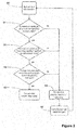
- FIG. 2 a flow diagram is provided showing the steps in operation of an induction cooker 10 of Figure 1 having a switch controller 24 modified to implement a cyclic monitoring process according to the present disclosure.
- Each cycle of monitoring steps may be triggered, beginning at STEP 50, as often as required to enable the controller 24 to respond to an onset of magnetic saturation.
- inductance of the induction coil 12 is measured and compared with a predetermined threshold inductance value. If the measured inductance value is greater than or equal to the predetermined threshold inductance value then the induction coil 12 is determined, at STEP 54, to be operating correctly and operation of the cooker continues.
- the measured inductance is found to be less than the predetermined threshold inductance value then, at STEP 56, the current flowing through the induction coil 12 is measured and compared with a predetermined threshold current value. If the measured current value is lower than or equal to the predetermined threshold current value then, at STEP 54, it is determined that the induction coil is operating correctly and operation of the cooker continues.
- the switch controller 24 tends to lower the ON time of the transistors 22 to control the current. Therefore, if at STEP 56 the measured current is found to be greater than the predetermined threshold current value then, in a further STEP 58, the conduction time of the one or more transistor switches 22, as determined by the switch controller 24, is compared with a predetermined threshold conduction time value. If the determined conduction time is greater than or equal to the predetermined threshold conduction time value then, at STEP 54, it is determined that the induction coil is operating correctly and operation of the cooker continues.
- the measured transistor conduction time is found to be lower than the threshold conduction time limit value then, at STEP 60, it is determined that induction coil saturation has occurred and operation of the induction heating process is terminated.
- the process enters a delay of a predetermined duration before returning to STEP 50 to begin the monitoring process again.
- the controller 24 is arranged to complete all of the steps 50 to 58 of a monitoring cycle within, for example, a 10ms time period.
- measurement of inductance may be achieved by monitoring changes in voltage over predetermined time intervals across the induction coil 12 and across a resistor (not shown in Figure 1 ) connected in series with the induction coil 12.
- Such voltage measurements across a resistor connected in series with the induction coil 12 may also be used to determine the instant current flowing through the induction coil 12 at predetermined time intervals and hence the rate of change of current.
- Conduction times of the transistor switches may also be determined from changing current values measured over a switching cycle of the respective switch.
- the threshold for the measured inductance value may be set at least 30% below the normal operating value of the inductance.
- the threshold for the measured current value may be set at least 30% greater than maximum normal operating current value.
- the threshold for the measured conduction time of the transistor switches may be set to be a value 20% greater than a known minimum operating conduction time.
- An induction cooker switch controller 24, modified to implement aspects described herein, may be a processor or processing system or circuitry provided by a single chip or integrated circuit or plural chips or integrated circuits, optionally provided as a chipset, an application-specific integrated circuit (ASIC), field-programmable gate array (FPGA), digital signal processor (DSP), etc.
- the chip or chips may comprise circuitry (as well as possibly firmware) for embodying at least one or more of a data processor or processors and a digital signal processor or processors, which are configurable so as to operate in accordance with the exemplary embodiments.
- the exemplary embodiments may be implemented at least in part by computer software stored in (non-transitory) memory and executable by the processor, or by hardware, or by a combination of tangibly stored software and hardware (and tangibly stored firmware).
- Such values may be stored in data storage provided by a single data storage device or by plural devices. Suitable devices include for example a hard disk and non-volatile semiconductor memory.
Landscapes
- Physics & Mathematics (AREA)
- Electromagnetism (AREA)
- Induction Heating Cooking Devices (AREA)
Description
- The present disclosure relates to an induction cooker, a method for operating an induction cooker and a computer program.
- Induction cookers are known in which a varying electric current is passed through an induction coil, the coil therefore producing a corresponding varying electromagnetic field. The varying electromagnetic field induces a varying eddy current in a ferromagnetic cooking vessel or the like when the cooking vessel is placed in close proximity to the induction coil, which in turn heats the cooking vessel and therefore the contents of the cooking vessel. One or more transistors may be used to vary the frequency of supply of current to the induction coil and thereby control the power that is provided to the induction coil.
- According to a first aspect disclosed herein, there is provided a method for operating an induction cooker having a current source switchable by one or more semiconductor switches to supply a varying current to an induction coil at a selected frequency, the method comprising:
- (i) measuring inductance of the induction coil and comparing the measured inductance with a predetermined threshold inductance value;
- (ii) if, at step (i), the measured inductance is lower than the predetermined threshold inductance value, measuring the electric current flowing through the induction coil and comparing the measured current with a predetermined threshold current value, otherwise continuing operation of the induction cooker;
- (iii) if, at step (ii), the measured current is greater than the predetermined threshold current value, measuring the conduction time of the one or more semiconductor switches and comparing the measured conduction time with a predetermined threshold conduction time value, otherwise continuing operation of the induction cooker; and
- (iv) if, at step (iii), the measured conduction time value is lower than the predetermined threshold conduction time value, terminating the supply of current to the inductance coil, otherwise continuing operation of the induction cooker.
- By this method, a more reliable determination of the onset of magnetic saturation may be achieved and an appropriate response may be triggered, in particular to cease a supply of current to the induction coil.
- In an example embodiment, the method may comprise:
- (v) following a predetermined time period of operating the induction cooker, repeating steps (i) to (iv).
- The monitoring process steps of the present invention may be operated in a cyclic manner with a predetermined delay between each operation of the method.
- In an example embodiment, the method may comprise operating steps (i) to (iv) within a predetermined monitoring time period. The predetermined time period may be for example 10ms.
- According to a second aspect disclosed herein, there is provided an induction cooker, comprising
an induction coil within a resonant converter circuit;
a switching arrangement comprising one or more semiconductor switches linked to a current source; and
a switch controller arranged to control the switching arrangement to supply a varying electric current at a selected frequency to the induction coil,
wherein the switch controller is arranged selectively to receive measurements of induction coil inductance, induction coil current and semiconductor conduction time from respective measurement means and to determine, by comparison of the measurements with respective predetermined threshold operating values, whether the induction coil has reached magnetic saturation and, if so, to terminate the supply of current to the induction coil. - In an example embodiment of the induction cooker, the switch controller is arranged to determine that the induction coil has reached magnetic saturation if each of the inductance, current and conduction time measurements are found respectively to be lower than, greater than and lower than the predetermined threshold operating values of inductance, current and conduction time, within a predetermined time period. The time period may be for example 10ms.
- According to a third aspect disclosed herein, there is provided an induction cooker switch controller, comprising a data processor programmed to implement a method as described above.
- According to a fourth aspect disclosed herein, there is provided a computer program product comprising computer program code which when installed in and executed by a computer processor causes the computer processor to implement a method as described above.
- To assist understanding of the present disclosure and to show how embodiments may be put into effect, reference is made by way of example to the accompanying drawings in which:
-
Figure 1 shows schematically a simplified electrical circuit showing the main components in a known induction cooker in which embodiments of the present disclosure may be implemented; and -
Figure 2 is a flow diagram showing steps in a monitoring process according to the present disclosure as may be implemented in an induction cooker, for example as shown inFigure 1 . - One example of a known induction cooker having an electrical circuit and a controller will firstly be described with reference to
Figure 1 . An example embodiment of the present invention will then be described with reference toFigure 2 as a modification to the induction cooker ofFigure 1 . - Referring firstly to
Figure 1 , there is shown a circuit diagram for a known example induction cooker 10. The induction cooker 10 has aninduction coil 12. As will be discussed further below, a varying electric current is provided to theinduction coil 12, which therefore produces a corresponding varying electromagnetic field. When a ferromagnetic object is placed close to theinduction coil 12 and therefore within the varying electromagnetic field, a corresponding varying eddy current is induced in the ferromagnetic object which heats the ferromagnetic object. The ferromagnetic object may be acooking vessel 30 such as a cooking pot, saucepan or frying pan. - In the example circuit shown, the
induction coil 12 is connected in a bridged arrangement with a network ofcapacitors 14. Theinduction coil 12 and the capacitor network form a resonant converter (which term as used herein includes so-called "quasi-resonant" converters unless the context requires otherwise) which resonates at a specific frequency. - Many induction cookers are intended to be run from an AC (alternating current) mains electric power supply. However, the current is not used directly from the mains power supply as the mains power supply is typically at a frequency of between 50 to 60 Hz or so, which can cause an unpleasant audible hum if used directly to power the
induction coil 12. Accordingly, in this example, the incomingAC mains power 16 is passed through afilter 18 and then to arectifier 20, which may for example be a diode bridge rectifier, which rectifies the AC to DC (direct current) which is then smoothed by acapacitor 21. - As mentioned, a varying current must be provided to the
induction coil 12 in order to produce the required varying electromagnetic field. In the circuit shown inFigure 1 , this is achieved by regulating or varying the current at a constant voltage using a pair of "power" transistors, configured in a half-bridge switching topology. Single switch topologies and full bridge switching topologies are also known for lower power and higher power induction cookers respectively. In the half-bridge topology inFigure 1 , a pair ofswitching transistors 22 is controlled by aswitch controller 24 to switch on and off using a pulse width modulation (PWM) technique to produce a varying electric current, at or near to the resonant frequency of the resonant converter, wherein the current level is adjusted according to the required working power level of the cooker 10 by varying the conduction time (pulse width) of eachtransistor 22. However, the type ofcooking vessel 30 being used can cause the resonant frequency of the resonant converter to vary. - The
power transistors 22 are required to withstand the high voltages and/or currents that are used: for example, to achieve a total power of the induction cooker 10 of, say, 3500W, currents flowing through the switching transistor(s) may be, say, 15A. Metal Oxide Semiconductor Field Effect Transistors (MOSFETs) or Insulated Gate Bipolar Transistors (IGBTs) are, for example, commonly used in such induction cooker switching applications where switching frequencies in the range of 10 kHz to 90 kHz would be typical. If IGBT devices are used, in particular,freewheeling diodes 26 may be connected in parallel to minimise current loss in the reverse conducting direction during switching. - A known problem in the operation of an induction cooker 10 such as that shown in
Figure 1 occurs when theinduction coil 12 reaches magnetic saturation and all of the magnetic domains in theferromagnetic cooking vessel 30 become aligned to the field. In such a situation, inductance of theinduction coil 12 falls. Magnetic saturation may be reached at different stages with different types ofcooking vessel 30, according to their respective ferromagnetic properties. As magnetic saturation approaches, the fall in induction coil inductance results in symptoms such as a rapid rise in the current levels flowing in the switching network. Various techniques are known by which to respond to the symptoms of magnetic saturation, including the use of current limiters. - In the present disclosure, a different approach is used in which an onset of magnetic saturation may be detected by an induction cooker controller and actions taken to avoid an unsafe condition. In one example embodiment of the present invention, a three stage cyclic monitoring process, as will now be described with reference to
Figure 2 , may for example be implemented in a modification to thecontroller 24 by including steps of the cyclic monitoring process of the present invention in an otherwise conventional control process for operating of the induction cooker 10. The cyclic monitoring process of the present disclosure is based upon a realisation by the inventors that, to detect an onset of magnetic saturation, it may not be enough simply to monitor changes in the inductance of theinduction coil 12. - Referring additionally to
Figure 2 , a flow diagram is provided showing the steps in operation of an induction cooker 10 ofFigure 1 having aswitch controller 24 modified to implement a cyclic monitoring process according to the present disclosure. Each cycle of monitoring steps may be triggered, beginning atSTEP 50, as often as required to enable thecontroller 24 to respond to an onset of magnetic saturation. - Firstly, at
STEP 52, inductance of theinduction coil 12 is measured and compared with a predetermined threshold inductance value. If the measured inductance value is greater than or equal to the predetermined threshold inductance value then theinduction coil 12 is determined, atSTEP 54, to be operating correctly and operation of the cooker continues. - If, at
STEP 52, the measured inductance is found to be less than the predetermined threshold inductance value then, atSTEP 56, the current flowing through theinduction coil 12 is measured and compared with a predetermined threshold current value. If the measured current value is lower than or equal to the predetermined threshold current value then, atSTEP 54, it is determined that the induction coil is operating correctly and operation of the cooker continues. - In a typical induction cooker, for example as described above with reference to
Figure 1 , when saturation of theinduction coil 12 occurs, the instant current through theinduction coil 12 increases and theswitch controller 24 tends to lower the ON time of thetransistors 22 to control the current. Therefore, if atSTEP 56 the measured current is found to be greater than the predetermined threshold current value then, in afurther STEP 58, the conduction time of the one or more transistor switches 22, as determined by theswitch controller 24, is compared with a predetermined threshold conduction time value. If the determined conduction time is greater than or equal to the predetermined threshold conduction time value then, atSTEP 54, it is determined that the induction coil is operating correctly and operation of the cooker continues. - If, at
STEP 58, the measured transistor conduction time is found to be lower than the threshold conduction time limit value then, atSTEP 60, it is determined that induction coil saturation has occurred and operation of the induction heating process is terminated. - If, at
STEP 54, it is determined that theinduction coil 12 is operating correctly then, atSTEP 62, the process enters a delay of a predetermined duration before returning toSTEP 50 to begin the monitoring process again. Thecontroller 24 is arranged to complete all of thesteps 50 to 58 of a monitoring cycle within, for example, a 10ms time period. - Known techniques and devices as would be within the knowledge and skills of a person of ordinary skill in the relevant art may be included in the circuit of
Figure 1 , for example, to make the inductance and current measurements referred to atsteps Figure 2 and to communicate the results of those measurements to thecontroller 24. Furthermore, known techniques and devices as would be apparent to that same notional skilled person may be used to establish the predetermined operating limit values, either by design or through measurement and analysis, to be used in those monitoring steps to assess whether theinduction coil 12 is operating correctly. - For example, measurement of inductance may be achieved by monitoring changes in voltage over predetermined time intervals across the
induction coil 12 and across a resistor (not shown inFigure 1 ) connected in series with theinduction coil 12. Such voltage measurements across a resistor connected in series with theinduction coil 12 may also be used to determine the instant current flowing through theinduction coil 12 at predetermined time intervals and hence the rate of change of current. Conduction times of the transistor switches may also be determined from changing current values measured over a switching cycle of the respective switch. - When setting the thresholds for the predetermined limit values of inductance (STEP 52), electric current (STEP 56) and switch conduction time (STEP 58), appropriate tolerance values may be applied beyond which the respective comparisons will be found to indicate incorrect induction coil operation. For example, the threshold for the measured inductance value may be set at least 30% below the normal operating value of the inductance. As another example, the threshold for the measured current value may be set at least 30% greater than maximum normal operating current value. As another example, the threshold for the measured conduction time of the transistor switches may be set to be a
value 20% greater than a known minimum operating conduction time. - An induction
cooker switch controller 24, modified to implement aspects described herein, may be a processor or processing system or circuitry provided by a single chip or integrated circuit or plural chips or integrated circuits, optionally provided as a chipset, an application-specific integrated circuit (ASIC), field-programmable gate array (FPGA), digital signal processor (DSP), etc. The chip or chips may comprise circuitry (as well as possibly firmware) for embodying at least one or more of a data processor or processors and a digital signal processor or processors, which are configurable so as to operate in accordance with the exemplary embodiments. In this regard, the exemplary embodiments may be implemented at least in part by computer software stored in (non-transitory) memory and executable by the processor, or by hardware, or by a combination of tangibly stored software and hardware (and tangibly stored firmware). - Where reference is made herein to predetermined values, such values may be stored in data storage provided by a single data storage device or by plural devices. Suitable devices include for example a hard disk and non-volatile semiconductor memory.
- The examples described herein are to be understood as illustrative examples of embodiments of the invention. Further embodiments and examples are envisaged, in particular applying the principles and techniques embodied by the present invention to other induction cooker switching topologies as would be known to a notional skilled person in this field.
- Any feature described in relation to any one example or embodiment may be used alone or in combination with other features. In addition, any feature described in relation to any one example or embodiment may also be used in combination with one or more features of any other of the examples or embodiments, or any combination of any other of the examples or embodiments. Furthermore, equivalents and modifications not described herein may also be employed within the scope of the invention, which is defined in the claims.
Claims (11)
- A method for operating an induction cooker having a current source (16, 18, 20, 21) switchable by one or more semiconductor switches (22) to supply a varying current to an induction coil (12) at a selected frequency, the method comprising:(i) measuring inductance of the induction coil and comparing the measured inductance with a predetermined threshold inductance value;(ii) if, at step (i), the measured inductance is lower than the predetermined threshold inductance value, measuring the electric current flowing through the induction coil and comparing the measured current with a predetermined threshold current value, otherwise continuing operation of the induction cooker;(iii) if, at step (ii), the measured current is greater than the predetermined threshold current value, measuring the conduction time of the one or more semiconductor switches and comparing the measured conduction time with a predetermined threshold conduction time value, otherwise continuing operation of the induction cooker; and(iv) if, at step (iii), the measured conduction time value is lower than the predetermined threshold conduction time value, terminating the supply of current to the inductance coil, otherwise continuing operation of the induction cooker.
- The method according to claim 1, comprising:(v) following a predetermined time period of operating the induction cooker, repeating steps (i) to (iv).
- The method according to claim 1 or claim 2, comprising operating steps (i) to (iv) within a predetermined monitoring time period.
- An induction cooker, comprising
an induction coil within a resonant converter circuit;
a switching arrangement comprising one or more semiconductor switches linked to a current source; and
a switch controller arranged to control the switching arrangement to supply a varying electric current at a selected frequency to the induction coil,
wherein the switch controller is arranged selectively to receive measurements of induction coil inductance, induction coil current and semiconductor conduction time from respective measurement means and to determine, by comparison of the measurements with respective predetermined threshold operating values, whether the induction coil has reached magnetic saturation and, if so, to terminate the supply of current to the induction coil. - The induction cooker according to claim 4, wherein the switch controller is arranged to determine that the induction coil has reached magnetic saturation if each of the inductance, current and conduction time measurements are found respectively to be lower than, greater than and lower than the predetermined threshold operating values of inductance, current and conduction time, within a predetermined time period.
- An induction cooker switch controller (24), comprising a data processor programmed to implement a method for operating an induction cooker having a current source (16, 18, 20, 21) switchable by one or more semiconductor switches (22) to supply a varying current to an induction coil (12) at a selected frequency, the method comprising:(i) measuring inductance of the induction coil and comparing the measured inductance with a predetermined threshold inductance value;(ii) if, at step (i), the measured inductance is lower than the predetermined threshold inductance value, measuring the electric current flowing through the induction coil and comparing the measured current with a predetermined threshold current value, otherwise continuing operation of the induction cooker;(iii) if, at step (ii), the measured current is greater than the predetermined threshold current value, measuring the conduction time of the one or more semiconductor switches and comparing the measured conduction time with a predetermined threshold conduction time value, otherwise continuing operation of the induction cooker; and(iv) if, at step (iii), the measured conduction time value is lower than the predetermined threshold conduction time value, terminating the supply of current to the inductance coil, otherwise continuing operation of the induction cooker.
- The induction cooker switch controller according to claim 6, the method comprising:(v) following a predetermined time period of operating the induction cooker, repeating steps (i) to (iv).
- The induction cooker switch controller according to claim 6 or claim 7, the method comprising operating steps (i) to (iv) within a predetermined monitoring time period.
- A computer program comprising computer program code which when installed in and executed by a computer processor causes the computer processor to implement a method for operating an induction cooker having a current source (16, 18, 20, 21) switchable by one or more semiconductor switches (22) to supply a varying current to an induction coil (12) at a selected frequency, the method comprising:(i) measuring inductance of the induction coil and comparing the measured inductance with a predetermined threshold inductance value;(ii) if, at step (i), the measured inductance is lower than the predetermined threshold inductance value, measuring the electric current flowing through the induction coil and comparing the measured current with a predetermined threshold current value, otherwise continuing operation of the induction cooker;(iii) if, at step (ii), the measured current is greater than the predetermined threshold current value, measuring the conduction time of the one or more semiconductor switches and comparing the measured conduction time with a predetermined threshold conduction time value, otherwise continuing operation of the induction cooker; and(iv) if, at step (iii), the measured conduction time value is lower than the predetermined threshold conduction time value, terminating the supply of current to the inductance coil, otherwise continuing operation of the induction cooker.
- The computer program according to claim 9, the method comprising:(v) following a predetermined time period of operating the induction cooker, repeating steps (i) to (iv).
- The computer program according to claim 9 or claim 10, the method comprising operating steps (i) to (iv) within a predetermined monitoring time period.
Priority Applications (1)
| Application Number | Priority Date | Filing Date | Title |
|---|---|---|---|
| EP17182438.6A EP3432683B1 (en) | 2017-07-20 | 2017-07-20 | Induction cooker, method of operation and computer program |
Applications Claiming Priority (1)
| Application Number | Priority Date | Filing Date | Title |
|---|---|---|---|
| EP17182438.6A EP3432683B1 (en) | 2017-07-20 | 2017-07-20 | Induction cooker, method of operation and computer program |
Publications (2)
| Publication Number | Publication Date |
|---|---|
| EP3432683A1 true EP3432683A1 (en) | 2019-01-23 |
| EP3432683B1 EP3432683B1 (en) | 2020-05-13 |
Family
ID=59383513
Family Applications (1)
| Application Number | Title | Priority Date | Filing Date |
|---|---|---|---|
| EP17182438.6A Active EP3432683B1 (en) | 2017-07-20 | 2017-07-20 | Induction cooker, method of operation and computer program |
Country Status (1)
| Country | Link |
|---|---|
| EP (1) | EP3432683B1 (en) |
Citations (3)
| Publication number | Priority date | Publication date | Assignee | Title |
|---|---|---|---|---|
| GB2155707A (en) * | 1984-02-09 | 1985-09-25 | Sanyo Electric Co | Control of induction heating apparatus |
| EP0713350A1 (en) * | 1994-11-15 | 1996-05-22 | Compagnie Europeenne Pour L'equipement Menager "Cepem" | Induction cooking surface with temperature protected inductor |
| EP2437573A1 (en) * | 2009-05-26 | 2012-04-04 | Mitsubishi Electric Corporation | Induction cooking device and induction heating method |
-
2017
- 2017-07-20 EP EP17182438.6A patent/EP3432683B1/en active Active
Patent Citations (3)
| Publication number | Priority date | Publication date | Assignee | Title |
|---|---|---|---|---|
| GB2155707A (en) * | 1984-02-09 | 1985-09-25 | Sanyo Electric Co | Control of induction heating apparatus |
| EP0713350A1 (en) * | 1994-11-15 | 1996-05-22 | Compagnie Europeenne Pour L'equipement Menager "Cepem" | Induction cooking surface with temperature protected inductor |
| EP2437573A1 (en) * | 2009-05-26 | 2012-04-04 | Mitsubishi Electric Corporation | Induction cooking device and induction heating method |
Also Published As
| Publication number | Publication date |
|---|---|
| EP3432683B1 (en) | 2020-05-13 |
Similar Documents
| Publication | Publication Date | Title |
|---|---|---|
| JP5586433B2 (en) | Method and induction heating apparatus for determining the temperature of a cooking vessel base heated by an induction heating coil | |
| EP2932794B1 (en) | An induction heating cooktop | |
| US11678410B2 (en) | Determining presence of compatible cookware in induction heating systems | |
| TWI565366B (en) | Heating apparatus having cooking container position detecting function | |
| KR100629334B1 (en) | Induction heating cooker and its operation method | |
| KR101462093B1 (en) | Electric range with oven detection function | |
| US11979963B2 (en) | Induction-heating cooking apparatus | |
| EP3796753A1 (en) | Induction heating device having improved output control function | |
| KR102175634B1 (en) | Cooker improving operation stability and operating method thereof | |
| WO2014090874A1 (en) | An induction heating cooktop | |
| EP2939499B1 (en) | An induction heating cooktop | |
| EP3432683B1 (en) | Induction cooker, method of operation and computer program | |
| WO2014090872A1 (en) | An induction heating cooktop | |
| KR102142412B1 (en) | Cooker reducing Electro Magnetic Interference and Operating method thereof | |
| JP4193143B2 (en) | Induction heating cooker | |
| CN110099469B (en) | Electromagnetic induction heating device and protection control circuit thereof | |
| KR102877687B1 (en) | Induction heating apparatus | |
| JP3376227B2 (en) | Inverter device | |
| KR102238457B1 (en) | Cooker for performing surge detection and operating method thereof | |
| EP3419382B1 (en) | Induction cooker and a method of operation | |
| JP3614736B2 (en) | Induction heating cooker | |
| US20230217553A1 (en) | Induction Cooktop and Method for an Induction Cooktop | |
| KR100712840B1 (en) | Induction heating cooker and its current control method | |
| JP5340026B2 (en) | Induction heating cooker | |
| KR100740317B1 (en) | Resonance Voltage Control System and Induction Control Method of Induction Heating Cooker |
Legal Events
| Date | Code | Title | Description |
|---|---|---|---|
| PUAI | Public reference made under article 153(3) epc to a published international application that has entered the european phase |
Free format text: ORIGINAL CODE: 0009012 |
|
| STAA | Information on the status of an ep patent application or granted ep patent |
Free format text: STATUS: THE APPLICATION HAS BEEN PUBLISHED |
|
| AK | Designated contracting states |
Kind code of ref document: A1 Designated state(s): AL AT BE BG CH CY CZ DE DK EE ES FI FR GB GR HR HU IE IS IT LI LT LU LV MC MK MT NL NO PL PT RO RS SE SI SK SM TR |
|
| AX | Request for extension of the european patent |
Extension state: BA ME |
|
| STAA | Information on the status of an ep patent application or granted ep patent |
Free format text: STATUS: REQUEST FOR EXAMINATION WAS MADE |
|
| 17P | Request for examination filed |
Effective date: 20190723 |
|
| RBV | Designated contracting states (corrected) |
Designated state(s): AL AT BE BG CH CY CZ DE DK EE ES FI FR GB GR HR HU IE IS IT LI LT LU LV MC MK MT NL NO PL PT RO RS SE SI SK SM TR |
|
| GRAP | Despatch of communication of intention to grant a patent |
Free format text: ORIGINAL CODE: EPIDOSNIGR1 |
|
| STAA | Information on the status of an ep patent application or granted ep patent |
Free format text: STATUS: GRANT OF PATENT IS INTENDED |
|
| RIC1 | Information provided on ipc code assigned before grant |
Ipc: H05B 6/06 20060101AFI20191114BHEP |
|
| INTG | Intention to grant announced |
Effective date: 20191128 |
|
| GRAS | Grant fee paid |
Free format text: ORIGINAL CODE: EPIDOSNIGR3 |
|
| GRAA | (expected) grant |
Free format text: ORIGINAL CODE: 0009210 |
|
| STAA | Information on the status of an ep patent application or granted ep patent |
Free format text: STATUS: THE PATENT HAS BEEN GRANTED |
|
| AK | Designated contracting states |
Kind code of ref document: B1 Designated state(s): AL AT BE BG CH CY CZ DE DK EE ES FI FR GB GR HR HU IE IS IT LI LT LU LV MC MK MT NL NO PL PT RO RS SE SI SK SM TR |
|
| REG | Reference to a national code |
Ref country code: GB Ref legal event code: FG4D |
|
| REG | Reference to a national code |
Ref country code: CH Ref legal event code: EP |
|
| REG | Reference to a national code |
Ref country code: DE Ref legal event code: R096 Ref document number: 602017016355 Country of ref document: DE |
|
| REG | Reference to a national code |
Ref country code: AT Ref legal event code: REF Ref document number: 1271936 Country of ref document: AT Kind code of ref document: T Effective date: 20200615 |
|
| REG | Reference to a national code |
Ref country code: LT Ref legal event code: MG4D |
|
| REG | Reference to a national code |
Ref country code: NL Ref legal event code: MP Effective date: 20200513 |
|
| PG25 | Lapsed in a contracting state [announced via postgrant information from national office to epo] |
Ref country code: SE Free format text: LAPSE BECAUSE OF FAILURE TO SUBMIT A TRANSLATION OF THE DESCRIPTION OR TO PAY THE FEE WITHIN THE PRESCRIBED TIME-LIMIT Effective date: 20200513 Ref country code: IS Free format text: LAPSE BECAUSE OF FAILURE TO SUBMIT A TRANSLATION OF THE DESCRIPTION OR TO PAY THE FEE WITHIN THE PRESCRIBED TIME-LIMIT Effective date: 20200913 Ref country code: PT Free format text: LAPSE BECAUSE OF FAILURE TO SUBMIT A TRANSLATION OF THE DESCRIPTION OR TO PAY THE FEE WITHIN THE PRESCRIBED TIME-LIMIT Effective date: 20200914 Ref country code: NO Free format text: LAPSE BECAUSE OF FAILURE TO SUBMIT A TRANSLATION OF THE DESCRIPTION OR TO PAY THE FEE WITHIN THE PRESCRIBED TIME-LIMIT Effective date: 20200813 Ref country code: FI Free format text: LAPSE BECAUSE OF FAILURE TO SUBMIT A TRANSLATION OF THE DESCRIPTION OR TO PAY THE FEE WITHIN THE PRESCRIBED TIME-LIMIT Effective date: 20200513 Ref country code: LT Free format text: LAPSE BECAUSE OF FAILURE TO SUBMIT A TRANSLATION OF THE DESCRIPTION OR TO PAY THE FEE WITHIN THE PRESCRIBED TIME-LIMIT Effective date: 20200513 Ref country code: GR Free format text: LAPSE BECAUSE OF FAILURE TO SUBMIT A TRANSLATION OF THE DESCRIPTION OR TO PAY THE FEE WITHIN THE PRESCRIBED TIME-LIMIT Effective date: 20200814 |
|
| PGFP | Annual fee paid to national office [announced via postgrant information from national office to epo] |
Ref country code: DE Payment date: 20200729 Year of fee payment: 4 |
|
| PG25 | Lapsed in a contracting state [announced via postgrant information from national office to epo] |
Ref country code: LV Free format text: LAPSE BECAUSE OF FAILURE TO SUBMIT A TRANSLATION OF THE DESCRIPTION OR TO PAY THE FEE WITHIN THE PRESCRIBED TIME-LIMIT Effective date: 20200513 Ref country code: RS Free format text: LAPSE BECAUSE OF FAILURE TO SUBMIT A TRANSLATION OF THE DESCRIPTION OR TO PAY THE FEE WITHIN THE PRESCRIBED TIME-LIMIT Effective date: 20200513 Ref country code: BG Free format text: LAPSE BECAUSE OF FAILURE TO SUBMIT A TRANSLATION OF THE DESCRIPTION OR TO PAY THE FEE WITHIN THE PRESCRIBED TIME-LIMIT Effective date: 20200813 Ref country code: HR Free format text: LAPSE BECAUSE OF FAILURE TO SUBMIT A TRANSLATION OF THE DESCRIPTION OR TO PAY THE FEE WITHIN THE PRESCRIBED TIME-LIMIT Effective date: 20200513 |
|
| REG | Reference to a national code |
Ref country code: AT Ref legal event code: MK05 Ref document number: 1271936 Country of ref document: AT Kind code of ref document: T Effective date: 20200513 |
|
| PG25 | Lapsed in a contracting state [announced via postgrant information from national office to epo] |
Ref country code: NL Free format text: LAPSE BECAUSE OF FAILURE TO SUBMIT A TRANSLATION OF THE DESCRIPTION OR TO PAY THE FEE WITHIN THE PRESCRIBED TIME-LIMIT Effective date: 20200513 Ref country code: AL Free format text: LAPSE BECAUSE OF FAILURE TO SUBMIT A TRANSLATION OF THE DESCRIPTION OR TO PAY THE FEE WITHIN THE PRESCRIBED TIME-LIMIT Effective date: 20200513 |
|
| PG25 | Lapsed in a contracting state [announced via postgrant information from national office to epo] |
Ref country code: RO Free format text: LAPSE BECAUSE OF FAILURE TO SUBMIT A TRANSLATION OF THE DESCRIPTION OR TO PAY THE FEE WITHIN THE PRESCRIBED TIME-LIMIT Effective date: 20200513 Ref country code: IT Free format text: LAPSE BECAUSE OF FAILURE TO SUBMIT A TRANSLATION OF THE DESCRIPTION OR TO PAY THE FEE WITHIN THE PRESCRIBED TIME-LIMIT Effective date: 20200513 Ref country code: CZ Free format text: LAPSE BECAUSE OF FAILURE TO SUBMIT A TRANSLATION OF THE DESCRIPTION OR TO PAY THE FEE WITHIN THE PRESCRIBED TIME-LIMIT Effective date: 20200513 Ref country code: EE Free format text: LAPSE BECAUSE OF FAILURE TO SUBMIT A TRANSLATION OF THE DESCRIPTION OR TO PAY THE FEE WITHIN THE PRESCRIBED TIME-LIMIT Effective date: 20200513 Ref country code: SM Free format text: LAPSE BECAUSE OF FAILURE TO SUBMIT A TRANSLATION OF THE DESCRIPTION OR TO PAY THE FEE WITHIN THE PRESCRIBED TIME-LIMIT Effective date: 20200513 Ref country code: AT Free format text: LAPSE BECAUSE OF FAILURE TO SUBMIT A TRANSLATION OF THE DESCRIPTION OR TO PAY THE FEE WITHIN THE PRESCRIBED TIME-LIMIT Effective date: 20200513 Ref country code: DK Free format text: LAPSE BECAUSE OF FAILURE TO SUBMIT A TRANSLATION OF THE DESCRIPTION OR TO PAY THE FEE WITHIN THE PRESCRIBED TIME-LIMIT Effective date: 20200513 Ref country code: ES Free format text: LAPSE BECAUSE OF FAILURE TO SUBMIT A TRANSLATION OF THE DESCRIPTION OR TO PAY THE FEE WITHIN THE PRESCRIBED TIME-LIMIT Effective date: 20200513 |
|
| REG | Reference to a national code |
Ref country code: DE Ref legal event code: R097 Ref document number: 602017016355 Country of ref document: DE |
|
| PG25 | Lapsed in a contracting state [announced via postgrant information from national office to epo] |
Ref country code: PL Free format text: LAPSE BECAUSE OF FAILURE TO SUBMIT A TRANSLATION OF THE DESCRIPTION OR TO PAY THE FEE WITHIN THE PRESCRIBED TIME-LIMIT Effective date: 20200513 Ref country code: SK Free format text: LAPSE BECAUSE OF FAILURE TO SUBMIT A TRANSLATION OF THE DESCRIPTION OR TO PAY THE FEE WITHIN THE PRESCRIBED TIME-LIMIT Effective date: 20200513 Ref country code: MC Free format text: LAPSE BECAUSE OF FAILURE TO SUBMIT A TRANSLATION OF THE DESCRIPTION OR TO PAY THE FEE WITHIN THE PRESCRIBED TIME-LIMIT Effective date: 20200513 |
|
| REG | Reference to a national code |
Ref country code: CH Ref legal event code: PL |
|
| PLBE | No opposition filed within time limit |
Free format text: ORIGINAL CODE: 0009261 |
|
| STAA | Information on the status of an ep patent application or granted ep patent |
Free format text: STATUS: NO OPPOSITION FILED WITHIN TIME LIMIT |
|
| 26N | No opposition filed |
Effective date: 20210216 |
|
| REG | Reference to a national code |
Ref country code: BE Ref legal event code: MM Effective date: 20200731 |
|
| PG25 | Lapsed in a contracting state [announced via postgrant information from national office to epo] |
Ref country code: LI Free format text: LAPSE BECAUSE OF NON-PAYMENT OF DUE FEES Effective date: 20200731 Ref country code: LU Free format text: LAPSE BECAUSE OF NON-PAYMENT OF DUE FEES Effective date: 20200720 Ref country code: CH Free format text: LAPSE BECAUSE OF NON-PAYMENT OF DUE FEES Effective date: 20200731 Ref country code: FR Free format text: LAPSE BECAUSE OF NON-PAYMENT OF DUE FEES Effective date: 20200731 |
|
| PG25 | Lapsed in a contracting state [announced via postgrant information from national office to epo] |
Ref country code: SI Free format text: LAPSE BECAUSE OF FAILURE TO SUBMIT A TRANSLATION OF THE DESCRIPTION OR TO PAY THE FEE WITHIN THE PRESCRIBED TIME-LIMIT Effective date: 20200513 Ref country code: BE Free format text: LAPSE BECAUSE OF NON-PAYMENT OF DUE FEES Effective date: 20200731 |
|
| PG25 | Lapsed in a contracting state [announced via postgrant information from national office to epo] |
Ref country code: IE Free format text: LAPSE BECAUSE OF NON-PAYMENT OF DUE FEES Effective date: 20200720 |
|
| REG | Reference to a national code |
Ref country code: DE Ref legal event code: R119 Ref document number: 602017016355 Country of ref document: DE |
|
| GBPC | Gb: european patent ceased through non-payment of renewal fee |
Effective date: 20210720 |
|
| PG25 | Lapsed in a contracting state [announced via postgrant information from national office to epo] |
Ref country code: GB Free format text: LAPSE BECAUSE OF NON-PAYMENT OF DUE FEES Effective date: 20210720 Ref country code: DE Free format text: LAPSE BECAUSE OF NON-PAYMENT OF DUE FEES Effective date: 20220201 |
|
| PG25 | Lapsed in a contracting state [announced via postgrant information from national office to epo] |
Ref country code: MT Free format text: LAPSE BECAUSE OF FAILURE TO SUBMIT A TRANSLATION OF THE DESCRIPTION OR TO PAY THE FEE WITHIN THE PRESCRIBED TIME-LIMIT Effective date: 20200513 Ref country code: CY Free format text: LAPSE BECAUSE OF FAILURE TO SUBMIT A TRANSLATION OF THE DESCRIPTION OR TO PAY THE FEE WITHIN THE PRESCRIBED TIME-LIMIT Effective date: 20200513 |
|
| PG25 | Lapsed in a contracting state [announced via postgrant information from national office to epo] |
Ref country code: MK Free format text: LAPSE BECAUSE OF FAILURE TO SUBMIT A TRANSLATION OF THE DESCRIPTION OR TO PAY THE FEE WITHIN THE PRESCRIBED TIME-LIMIT Effective date: 20200513 |
|
| PGFP | Annual fee paid to national office [announced via postgrant information from national office to epo] |
Ref country code: TR Payment date: 20250718 Year of fee payment: 9 |