EP3432651A1 - Method and device for transmitting and receiving power headroom report - Google Patents
Method and device for transmitting and receiving power headroom report Download PDFInfo
- Publication number
- EP3432651A1 EP3432651A1 EP18194380.4A EP18194380A EP3432651A1 EP 3432651 A1 EP3432651 A1 EP 3432651A1 EP 18194380 A EP18194380 A EP 18194380A EP 3432651 A1 EP3432651 A1 EP 3432651A1
- Authority
- EP
- European Patent Office
- Prior art keywords
- pusch
- power headroom
- carrier component
- headroom report
- power
- Prior art date
- Legal status (The legal status is an assumption and is not a legal conclusion. Google has not performed a legal analysis and makes no representation as to the accuracy of the status listed.)
- Granted
Links
Images



Classifications
-
- H—ELECTRICITY
- H04—ELECTRIC COMMUNICATION TECHNIQUE
- H04W—WIRELESS COMMUNICATION NETWORKS
- H04W52/00—Power management, e.g. Transmission Power Control [TPC] or power classes
- H04W52/04—Transmission power control [TPC]
- H04W52/38—TPC being performed in particular situations
- H04W52/42—TPC being performed in particular situations in systems with time, space, frequency or polarisation diversity
-
- H—ELECTRICITY
- H04—ELECTRIC COMMUNICATION TECHNIQUE
- H04B—TRANSMISSION
- H04B17/00—Monitoring; Testing
- H04B17/20—Monitoring; Testing of receivers
- H04B17/24—Monitoring; Testing of receivers with feedback of measurements to the transmitter
-
- H—ELECTRICITY
- H04—ELECTRIC COMMUNICATION TECHNIQUE
- H04W—WIRELESS COMMUNICATION NETWORKS
- H04W24/00—Supervisory, monitoring or testing arrangements
- H04W24/10—Scheduling measurement reports ; Arrangements for measurement reports
-
- H—ELECTRICITY
- H04—ELECTRIC COMMUNICATION TECHNIQUE
- H04W—WIRELESS COMMUNICATION NETWORKS
- H04W52/00—Power management, e.g. Transmission Power Control [TPC] or power classes
- H04W52/04—Transmission power control [TPC]
- H04W52/30—Transmission power control [TPC] using constraints in the total amount of available transmission power
- H04W52/36—Transmission power control [TPC] using constraints in the total amount of available transmission power with a discrete range or set of values, e.g. step size, ramping or offsets
- H04W52/365—Power headroom reporting
-
- H—ELECTRICITY
- H04—ELECTRIC COMMUNICATION TECHNIQUE
- H04W—WIRELESS COMMUNICATION NETWORKS
- H04W52/00—Power management, e.g. Transmission Power Control [TPC] or power classes
- H04W52/04—Transmission power control [TPC]
- H04W52/30—Transmission power control [TPC] using constraints in the total amount of available transmission power
- H04W52/34—TPC management, i.e. sharing limited amount of power among users or channels or data types, e.g. cell loading
- H04W52/346—TPC management, i.e. sharing limited amount of power among users or channels or data types, e.g. cell loading distributing total power among users or channels
Definitions
- the present invention generally relates to a wireless communication system, and more particularly relates to a method and device for transmitting and receiving a power headroom report.
- power control is a key technology. Minimizing the interference in the wireless communication system, on the condition that communication quality is not affected, can be achieved by controlling the transmit power of each User Equipment (UE) and Base Station (BS or eNB), thereby maximizing the system capacity. In addition, the power control further enables the user equipment to have longer standby time.
- UE User Equipment
- BS Base Station
- eNB Base Station
- the power control including opening and closing loops is carried out at the user equipment.
- the user equipment needs to transmit a power headroom report to the base station, and based on the received power headroom report, the base station derives a Power Spectral Density (PSD) used by a Physical Uplink Shared Channel (PUSCH) at the user equipment, and the remaining power headroom.
- PSD Power Spectral Density
- PUSCH Physical Uplink Shared Channel
- the base station can determine how many Resource Units (RUs) can be allocated to the user equipment and a Modulation and Coding Scheme (MCS) adapted to be used by the user equipment to guarantee obtaining an expected Signal to Interference plus Noise Ratio (SINR) on wireless links between the user equipment and the base station.
- MCS Modulation and Coding Scheme
- the aforesaid power headroom is defined as a difference between the allowed maximum transmit power of the user equipment and the current transmit power for PUSCH.
- LTE-A since multiple Carrier Components (CCs) are introduced, new features appear, such as supporting the power control specific to the carrier components, the simultaneous transmission of a Physical Uplink Control Channel (PUCCH) and the PUSCH, and one or more power amplifiers.
- PUCCH Physical Uplink Control Channel
- the user equipment transmitting power headroom reports to the base station becomes complex compared with LTE-Release 8, and currently, there is no power headroom report considering the new introduced features.
- P i min P C i MAX , 10 log 10 M PUSCH i + P O_PUSCH i + ⁇ i ⁇ PL i ⁇ F PL ⁇ f i + F PL ⁇ f i + ⁇ TF i + f ⁇ i
- P ⁇ PUCCH i P 0 _PUCCH i + PL i + h ⁇ + ⁇ F_PUCCH ⁇ + g i
- LTE Release10 In addition to the Time Division Multiplexing (TDM) between PUSCH and PUCCH that is currently done in LTE Release8, LTE Release10 also supports simultaneous transmission of PUCCH and PUSCH on the same carrier component.
- TDM Time Division Multiplexing
- the transmit power of the user equipment needs to be shared between the two channels so that the total transmit power on the i th carrier component equals to the sum of the transmit power of two channels, i.e.
- P i sum P i PUSCH + P i PUCCH
- P i sum is the total transmit power of the user equipment on the i th carrier component
- P i PUSCH is the transmit power of the PUSCH on the i th carrier component
- P i PUCCH is the transmit power of the PUCCH on the i th carrier component.
- the base station since the base station only receives the power headroom report including the final power headroom value and does not receive the power value used by the PUSCH and PUCCH on the i th carrier component, it is impossible for the base station to derive the power spectral density used by the PUSCH at the user equipment, and the remaining power headroom, and further it is impossible to accurately determine how many resource units need to be allocated to the carrier component, and thereby it is impossible to achieve accurate resource scheduling and allocating.
- the base station may effectively carry out resource allocating and scheduling to achieve the expected transmission quality.
- a method for transmitting a power headroom report comprising: forming, at a user equipment, a power headroom report specific to a carrier component simultaneously transmitting a physical uplink control channel, PUCCH, and a physical uplink shared channel, PUSCH; transmitting the power headroom report to a base station, wherein the power headroom report is included in a packet data unit of the PUSCH; and wherein the power headroom report comprises content items related to a PUSCH transmit power and a PUCCH transmit power, and wherein the content items include a first content item including P CMAX and P PUSCH and being dependent on a relationship between the two, and a second content item including P CMAX , P PUSCH , and P PUCCH and being dependent on a relationship between the three, where P CMAX denotes maximum transmit power allowed by the carrier component, , P PUSCH de
- the power headroom report is included in a packet data unit of a physical uplink shared channel transmitted on a carrier component.
- transmitting the power headroom report to the base station is triggered based on a period or an event specific to each carrier component.
- the period is a plurality of transmission time intervals or a certain timer value.
- the event is that since the previous power headroom report is transmitted, the change of the transmission path loss between the user equipment and the base station has exceeded a certain predetermined value or the user equipment has carried out a predetermined number of power control commands.
- the power headroom report includes content items related to a physical uplink shared channel transmit power and a physical uplink control channel transmit power.
- a method for receiving a power headroom report comprising: receiving, at a base station, a power headroom report specific to each carrier component from a user equipment; and based on the received power headroom report, determining a power spectral density and remaining power headroom of a physical uplink shared channel on the each carrier component, wherein the power headroom report is included in a packet data unit of a physical uplink shared channel transmitted on the carrier component; and wherein the power headroom report comprises content items related to a physical uplink shared channel transmit power and a physical uplink control channel transmit power, and wherein the content items include P i , CMAX ⁇ P i PUSCH and P i , CMAX ⁇ P i PUSCH ⁇ P i PUCCH , where P i , CMAX denotes maximum transmit power allowed by the i th carrier component, P i PUSCH denotes current physical uplink shared channel transmit power on the i th carrier component and P
- the method further comprises: based on the power spectral density and the remaining power headroom of the physical uplink shared channel, determining the number of resource units to be allocated to each carrier component and a modulation and coding scheme.
- a device for transmitting a power headroom report comprising: a forming module for forming, at a user equipment, a power headroom report specific to each carrier component; a transmitting module for transmitting the power headroom report to a base station, wherein the power headroom report is included in a packet data unit of a physical uplink shared channel transmitted on the carrier component; and wherein the power headroom report comprises content items related to a physical uplink shared channel transmit power and a physical uplink control channel transmit power, and wherein the content items include P i , CMAX ⁇ P i PUSCH and P i , CMAX ⁇ P i PUSCH ⁇ P i PUCCH , where P i , CMAX denotes maximum transmit power allowed by the i th carrier component, P i PUSCH denotes current physical uplink shared channel transmit power on the i th carrier component and P i PUCCH denotes current physical uplink control channel transmit power on
- a device for receiving a power headroom report comprising: a receiving module for receiving, at a base station, a power headroom report specific to each carrier component from a user equipment; a determining module for determining, based on the received power headroom report, a power spectral density and remaining power headroom of a physical uplink shared channel on the each carrier component, wherein the power headroom report is included in a packet data unit of a physical uplink shared channel transmitted on the carrier component; and wherein the power headroom report comprises content items related to a physical uplink shared channel transmit power and a physical uplink control channel transmit power, and wherein the content items include P i , CMAX ⁇ P i PUSCH and P i , CMAX ⁇ P i PUSCH ⁇ P i PUCCH , where P i , CMAX denotes maximum transmit power allowed by the i th carrier component, P i PUSCH denotes current physical uplink shared channel transmit
- a complete power headroom reporting mechanism can be provided to the LTE-A system having multiple new features (e.g. multiple carrier components, the simultaneous transmission of PUCCH and PUSCH on one carrier component, and one or more power amplifiers). Further, by receiving the power headroom report specific to each carrier component, a base station can correctly derive how many resource units need to be allocated to a user equipment, and a corresponding modulation and coding scheme so as to perform effective resource scheduling and guarantee transmission quality of wireless links.
- FIG. 1 where a wireless communication system to which a method according to the present invention may be applied is illustrated.
- the wireless communication system may be a 3GPP LTE-A system.
- a base station and a user equipment carry out wireless communication according to a method of the present invention, including: a user equipment transmitting a power headroom report (specific to each carrier component, and will be described below in detail) to a base station in an uplink (UL) direction, while the base station that provides a wireless access service, after receiving the power headroom report transmitted by the user equipment, determining a power spectral density and remaining power of the user equipment based on the received power headroom report to thereby determine the number of resource units to be allocated to the user equipment and a corresponding modulation and coding scheme so as to guarantee the expected signal to interference plus noise ratio of the wireless links between the base station and the user equipment.
- a power headroom report specifically to each carrier component, and will be described below in detail
- the base station transmits, at a downlink (DL) direction, the determined number of resource units and corresponding modulation and coding scheme to the user equipment.
- DL downlink
- the illustrated wireless communication system is only illustrative and its purpose is for explaining the principle of the present invention.
- the network elements, components and corresponding wireless communication processing procedures that are irrelevant to the method of the present invention but essential to wireless communication are omitted.
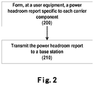
- FIG. 2 is a simplified flowchart exemplarily illustrating a method for transmitting a power headroom report according to the present invention.
- a power headroom report specific to each carrier component is formed at a user equipment.
- forming the power headroom report specific to each carrier component lies in considering based on the aforesaid open loop formula and closed loop power control command function specific to each carrier component, forming, on each carrier component, a power spectral density specific to the carrier component.
- the power headroom report about each carrier component should be transmitted to the base station.
- the power headroom report specific to each carrier component is included in a Packet Data Unit (PDU) transmitted over the PUSCH on the carrier component.
- PDU Packet Data Unit
- the power headroom report specific to the i th carrier component formed at the user equipment may relate to the maximum transmit power allowed by the i th carrier component, and the current PUSCH and PUCCH transmit power on the i th carrier component.
- the content items of the power headroom report specific to the i th carrier component formed at the user equipment can be expressed as below:
- the present invention does not transmit only one content item as Formula (4) like the existing technical solutions, but respectively transmits the transmit power situations about PUSCH and PUCCH in two items in the power headroom report specific to the i th carrier component, that is, the power headroom report provided by the present invention includes the contents items related to the PUSCH transmit power and the PUCCH transmit power to thereby overcome the defects existing in the existing technical solutions, while the base station can perform correct resource allocating or scheduling based on the power headroom report.
- the power headroom report specific to the i th carrier component formed at the user equipment may also relate to the aforesaid maximum transmit power allowed by the i th carrier component, and the current PUSCH transmit power and the potential PUCCH transmit power on the i th carrier component.
- the base station can perform correct resource allocating or scheduling for use in the future when transmitting data on PUSCH and PUCCH.
- a power headroom report is transmitted to a base station.
- transmitting the power headroom report to the base station may be triggered based on a period or an event specific to each carrier component.
- the period may be a plurality of transmission time intervals or a timer value in a unit of millisecond for example, while the event, for example, may be that since the previous power headroom report is transmitted, the change of the transmission path loss between the user equipment and the base station has exceeded a certain predetermined value or the user equipment has carried out a predetermined number of power control commands.
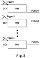
- FIG. 3 is a schematic diagram exemplarily illustrating the transmission of power headroom report according to embodiments of the present invention.
- the user equipment is allocated with a plurality of carrier components, e.g. CC1, CC2 ... CCn, wherein each carrier component has a trigger (periodic or event) specific to itself, e.g. trigger 1, trigger 2 ... trigger n, while a specific power headroom report is formed for each carrier component, e.g. PHI, PH2 ... PHn shown in FIG. 3 , and each power headroom report PHI, PH2 ... PHn includes various content items mentioned above.
- the power headroom reports included in the packet data unit are transmitted to the base station. For example, PH1 is transmitted on PUSCH 1; PH2 is transmitted on PUSCH2; ... while PHn is transmitted on PUSCHn.
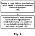
- FIG. 4 is a flowchart exemplarily illustrating a method for receiving a power headroom report according to an embodiment of the present invention.
- a power headroom report specific to each carrier component is received at a base station from a user equipment.
- the power spectral density and the remaining power headroom of the physical uplink shared channel on each carrier component are determined based on the received power headroom report. The determination process will be described below in detail:
- the base station can further determine an appropriate modulation and coding scheme based on the power headroom report transmitted by the user equipment. Specifically, the base station obtains the signal to interference plus noise ratio of PUSCH based on the derived power spectral density PSD i and the measured channel quality to thereby determine a modulation and coding scheme to be used by the user equipment and corresponding to the signal to interference plus noise ratio.
- FIG. 5 is a simplified block diagram illustrating a device 500 for transmitting a power headroom report according to an embodiment of the present invention.
- the device 500 comprises a forming module 510 and a transmitting module 520, wherein the forming module 510 is for forming, at a user equipment, a power headroom report specific to each carrier component, and the detailed forming process may refer to the above description with reference to FIG. 2 ; while the transmitting module 520 is for transmitting the power headroom report to a base station.
- FIG. 6 is a simplified block diagram exemplarily illustrating a device 600 for receiving a power headroom report according to an embodiment of the present invention.
- the device 600 comprises a receiving module 610 and a determining module 620, wherein the receiving module 610 is for receiving, at a base station, a power headroom report specific to each carrier component from a user equipment, while the determining module 620 is for determining, based on the received power headroom report, a power spectral density and remaining power headroom of a physical uplink shared channel on each carrier component, and the detailed determining process may refer to the above description with reference to FIG. 4 .
- a power headroom report specific to a carrier component relates to a difference between the maximum transmit power specific to the carrier component and the power used on the carrier component, while the maximum transmit power specific to the carrier component is not associated with the total transmit power of the user equipment, and thus when the base station performs resource scheduling, it only needs to be noted that the sum of the maximum transmit powers on all carrier components should not exceed the total transmit power of the user equipment. That is to say, forming a power headroom reporting mechanism specific to a carrier component in the present invention is not affected by one or more power amplifiers.
- the present invention may employ a form of complete hardware embodiments, complete software embodiments, or both.
- the present invention is implemented as software, including, without limitation to, firmware, resident software, micro-code, etc.
Landscapes
- Engineering & Computer Science (AREA)
- Computer Networks & Wireless Communication (AREA)
- Signal Processing (AREA)
- Physics & Mathematics (AREA)
- Electromagnetism (AREA)
- Mobile Radio Communication Systems (AREA)
Abstract
Description
- The present invention generally relates to a wireless communication system, and more particularly relates to a method and device for transmitting and receiving a power headroom report.
- In the wireless communication system, power control is a key technology. Minimizing the interference in the wireless communication system, on the condition that communication quality is not affected, can be achieved by controlling the transmit power of each User Equipment (UE) and Base Station (BS or eNB), thereby maximizing the system capacity. In addition, the power control further enables the user equipment to have longer standby time.
- At present, the power control including opening and closing loops is carried out at the user equipment. Based on such power control, the user equipment needs to transmit a power headroom report to the base station, and based on the received power headroom report, the base station derives a Power Spectral Density (PSD) used by a Physical Uplink Shared Channel (PUSCH) at the user equipment, and the remaining power headroom. Next, with the derived power spectral density and the remaining power headroom, the base station can determine how many Resource Units (RUs) can be allocated to the user equipment and a Modulation and Coding Scheme (MCS) adapted to be used by the user equipment to guarantee obtaining an expected Signal to Interference plus Noise Ratio (SINR) on wireless links between the user equipment and the base station.
- In the Third Generation Partnership Project (3GPP) Long Term Evolution (LTE), the aforesaid power headroom is defined as a difference between the allowed maximum transmit power of the user equipment and the current transmit power for PUSCH. In LTE-A, since multiple Carrier Components (CCs) are introduced, new features appear, such as supporting the power control specific to the carrier components, the simultaneous transmission of a Physical Uplink Control Channel (PUCCH) and the PUSCH, and one or more power amplifiers. Thus, the user equipment transmitting power headroom reports to the base station becomes complex compared with LTE-Release 8, and currently, there is no power headroom report considering the new introduced features.
- In addition, RANI under the Third Generation Partnership Project has agreed to carry out PUCCH and PUSCH power control specific to each carrier component, wherein the PUSCH power control formula for compensating the path loss due to frequency separation is as follows:

- P C
i MAX is the maximum transmit power of a user equipment on the ith carrier component; - MPUSCH (i) is the number of resource units allocated to the ith carrier component;
- P 0_PUSCH (i) and αi are open loop power control parameters specific to the ith carrier component;
- PLi is the estimated path loss for the ith carrier component;
- FPL (Δfi) is the path loss difference due to the frequency separation Δfi for the ith carrier component relative to the anchor carrier component;
- ΔTF(i) is the offset with respect to the transport format;
- f(Δ i ) is the function of the closed loop power control command.
- The full compensation for the PUCCH can be calculated via the following formula:

- P 0_PUCCH (i) is the sum of the cell specific parameter and the user equipment specific parameter specific to the ith carrier component;
- PL(i) is the estimated path loss for the ith carrier component;
- h(·) is the PUCCH format related parameter;
- Δ F_PUCCH (·) is the parameter corresponding to the PUCCH format 1a;
- g(i) is the function of the closed loop power control command on the ith carrier component.
- In RAN1#55bis, in addition to the Time Division Multiplexing (TDM) between PUSCH and PUCCH that is currently done in LTE Release8, LTE Release10 also supports simultaneous transmission of PUCCH and PUSCH on the same carrier component. Thus, the transmit power of the user equipment needs to be shared between the two channels so that the total transmit power on the i th carrier component equals to the sum of the transmit power of two channels, i.e. PUSCH and PUCCH, as expressed by the formula below:


- Based on the above formula (3), many existing technical solutions related to the power headroom report submit that since the base station knows the standardized rule used to allocate power between PUSCH and PUCCH, they propose to transmit to the base station the power headroom report calculated via the formula below:

- Thus, methods and devices for transmitting and receiving a power headroom report are needed to provide a complete power headroom reporting mechanism for the multiple new features (e.g. multiple carrier components, the simultaneous transmission of PUCCH and PUSCH on one carrier component, and one or more power amplifiers) introduced in LTE-A. Based on the power headroom reporting mechanism, the base station may effectively carry out resource allocating and scheduling to achieve the expected transmission quality.
- In view of the above problem existing in the prior art, the present invention provides a new solution as below:
According to one aspect of the present invention, there is provided a method for transmitting a power headroom report, comprising: forming, at a user equipment, a power headroom report specific to a carrier component simultaneously transmitting a physical uplink control channel, PUCCH, and a physical uplink shared channel, PUSCH; transmitting the power headroom report to a base station, wherein the power headroom report is included in a packet data unit of the PUSCH; and wherein the power headroom report comprises content items related to a PUSCH transmit power and a PUCCH transmit power, and wherein the content items include a first content item including PCMAX and PPUSCH and being dependent on a relationship between the two, and a second content item including PCMAX , PPUSCH , and PPUCCH and being dependent on a relationship between the three, where PCMAX denotes maximum transmit power allowed by the carrier component, , PPUSCH denotes a current PUSCH transmit power on the carrier component, and PPUCCH denotes a current PUCCH transmit power on the carrier component. - Preferably, the power headroom report is included in a packet data unit of a physical uplink shared channel transmitted on a carrier component.
- Preferably, transmitting the power headroom report to the base station is triggered based on a period or an event specific to each carrier component.
- Further preferably, the period is a plurality of transmission time intervals or a certain timer value.
- Further preferably, the event is that since the previous power headroom report is transmitted, the change of the transmission path loss between the user equipment and the base station has exceeded a certain predetermined value or the user equipment has carried out a predetermined number of power control commands.
- Preferably, the power headroom report includes content items related to a physical uplink shared channel transmit power and a physical uplink control channel transmit power.
- According to another aspect of the present invention, there is provided a method for receiving a power headroom report, comprising: receiving, at a base station, a power headroom report specific to each carrier component from a user equipment; and based on the received power headroom report, determining a power spectral density and remaining power headroom of a physical uplink shared channel on the each carrier component, wherein the power headroom report is included in a packet data unit of a physical uplink shared channel transmitted on the carrier component; and wherein the power headroom report comprises content items related to a physical uplink shared channel transmit power and a physical uplink control channel transmit power, and wherein the content items include


- Preferably, the method further comprises: based on the power spectral density and the remaining power headroom of the physical uplink shared channel, determining the number of resource units to be allocated to each carrier component and a modulation and coding scheme.
- According to one aspect of the present invention, there is provided a device for transmitting a power headroom report, comprising: a forming module for forming, at a user equipment, a power headroom report specific to each carrier component; a transmitting module for transmitting the power headroom report to a base station, wherein the power headroom report is included in a packet data unit of a physical uplink shared channel transmitted on the carrier component; and wherein the power headroom report comprises content items related to a physical uplink shared channel transmit power and a physical uplink control channel transmit power, and wherein the content items include



- According to another aspect of the present invention, there is provided a device for receiving a power headroom report, comprising: a receiving module for receiving, at a base station, a power headroom report specific to each carrier component from a user equipment; a determining module for determining, based on the received power headroom report, a power spectral density and remaining power headroom of a physical uplink shared channel on the each carrier component, wherein the power headroom report is included in a packet data unit of a physical uplink shared channel transmitted on the carrier component; and wherein the power headroom report comprises content items related to a physical uplink shared channel transmit power and a physical uplink control channel transmit power, and wherein the content items include


- By implementing the method and device as provided by the present invention, a complete power headroom reporting mechanism can be provided to the LTE-A system having multiple new features (e.g. multiple carrier components, the simultaneous transmission of PUCCH and PUSCH on one carrier component, and one or more power amplifiers). Further, by receiving the power headroom report specific to each carrier component, a base station can correctly derive how many resource units need to be allocated to a user equipment, and a corresponding modulation and coding scheme so as to perform effective resource scheduling and guarantee transmission quality of wireless links.
- Other features, objects and advantages of the present invention will become more obvious by making references to the following detailed description of nonrestrictive embodiments in conjunction with the accompanying drawings. In the accompanying drawings, the same and similar reference signs represent same or similar devices or method steps, in which:
-
FIG. 1 is a schematic diagram illustrating a wireless communication system to which a method according to the present invention may be applied; -
FIG. 2 is a simplified flowchart exemplarily illustrating a method for transmitting a power headroom report according to an embodiment of the present invention; -
FIG. 3 is a schematic diagram illustrating transmission of the power headroom report according to an embodiment of the present invention; -
FIG. 4 is a simplified flowchart exemplarily illustrating a method for receiving a power headroom report according to an embodiment of the present invention; -
FIG. 5 is a simplified block diagram exemplarily illustrating a device for transmitting a power headroom report according to an embodiment of the present invention; and -
FIG. 6 is a simplified block diagram exemplarily illustrating a device for receiving a power headroom report according to an embodiment of the present invention. - Embodiments of the present invention will be described below in detail by making references to the accompanying drawings.
- Reference is first made to
FIG. 1 , where a wireless communication system to which a method according to the present invention may be applied is illustrated. The wireless communication system, for example, may be a 3GPP LTE-A system. As illustrated inFIG. 1 , a base station and a user equipment carry out wireless communication according to a method of the present invention, including: a user equipment transmitting a power headroom report (specific to each carrier component, and will be described below in detail) to a base station in an uplink (UL) direction, while the base station that provides a wireless access service, after receiving the power headroom report transmitted by the user equipment, determining a power spectral density and remaining power of the user equipment based on the received power headroom report to thereby determine the number of resource units to be allocated to the user equipment and a corresponding modulation and coding scheme so as to guarantee the expected signal to interference plus noise ratio of the wireless links between the base station and the user equipment. Next, the base station transmits, at a downlink (DL) direction, the determined number of resource units and corresponding modulation and coding scheme to the user equipment. It needs to be pointed out that the illustrated wireless communication system is only illustrative and its purpose is for explaining the principle of the present invention. Furthermore, to avoid unnecessarily obscuring the principle of the present invention, the network elements, components and corresponding wireless communication processing procedures that are irrelevant to the method of the present invention but essential to wireless communication are omitted. -
FIG. 2 is a simplified flowchart exemplarily illustrating a method for transmitting a power headroom report according to the present invention. At step 200, a power headroom report specific to each carrier component is formed at a user equipment. In the present invention, forming the power headroom report specific to each carrier component lies in considering based on the aforesaid open loop formula and closed loop power control command function specific to each carrier component, forming, on each carrier component, a power spectral density specific to the carrier component. To enable a base station to determine the number of resource units allocated to the PUSCH on each carrier component of a served user equipment, the power headroom report about each carrier component should be transmitted to the base station. - Preferably, the power headroom report specific to each carrier component is included in a Packet Data Unit (PDU) transmitted over the PUSCH on the carrier component.
- When a user equipment simultaneously transmits PUCCH and PUSCH on the ith carrier component, the power headroom report specific to the ith carrier component formed at the user equipment may relate to the maximum transmit power allowed by the ith carrier component, and the current PUSCH and PUCCH transmit power on the ith carrier component. For example, for the ith carrier component, P i,CMAX = 24dBm = 251mw,


-


-


-


-


-


-


-


- From the above exemplary content items, it can be seen that the present invention does not transmit only one content item as Formula (4) like the existing technical solutions, but respectively transmits the transmit power situations about PUSCH and PUCCH in two items in the power headroom report specific to the ith carrier component, that is, the power headroom report provided by the present invention includes the contents items related to the PUSCH transmit power and the PUCCH transmit power to thereby overcome the defects existing in the existing technical solutions, while the base station can perform correct resource allocating or scheduling based on the power headroom report.
- In addition, it needs to be pointed out that although the user equipment may only transmit PUSCH on the ith carrier component at present, the power headroom report specific to the ith carrier component formed at the user equipment may also relate to the aforesaid maximum transmit power allowed by the ith carrier component, and the current PUSCH transmit power and the potential PUCCH transmit power on the ith carrier component. Thus, when a power headroom report similar to the above when PUSCH and PUCCH exist simultaneously is transmitted to a base station, the base station can perform correct resource allocating or scheduling for use in the future when transmitting data on PUSCH and PUCCH.
- Now returning to the flowchart of
FIG. 2 , atstep 210, a power headroom report is transmitted to a base station. - Preferably, transmitting the power headroom report to the base station may be triggered based on a period or an event specific to each carrier component. Here, the period may be a plurality of transmission time intervals or a timer value in a unit of millisecond for example, while the event, for example, may be that since the previous power headroom report is transmitted, the change of the transmission path loss between the user equipment and the base station has exceeded a certain predetermined value or the user equipment has carried out a predetermined number of power control commands.
-
FIG. 3 is a schematic diagram exemplarily illustrating the transmission of power headroom report according to embodiments of the present invention. As illustrated inFIG. 3 , the user equipment is allocated with a plurality of carrier components, e.g. CC1, CC2 ... CCn, wherein each carrier component has a trigger (periodic or event) specific to itself,e.g. trigger 1,trigger 2 ... trigger n, while a specific power headroom report is formed for each carrier component, e.g. PHI, PH2 ... PHn shown inFIG. 3 , and each power headroom report PHI, PH2 ... PHn includes various content items mentioned above. On the corresponding PUSCH, the power headroom reports included in the packet data unit are transmitted to the base station. For example, PH1 is transmitted onPUSCH 1; PH2 is transmitted on PUSCH2; ... while PHn is transmitted on PUSCHn. -
FIG. 4 is a flowchart exemplarily illustrating a method for receiving a power headroom report according to an embodiment of the present invention. Where, at step 410, a power headroom report specific to each carrier component is received at a base station from a user equipment. Next, atstep 420, the power spectral density and the remaining power headroom of the physical uplink shared channel on each carrier component are determined based on the received power headroom report. The determination process will be described below in detail: - After receiving the aforesaid power headroom report related to the maximum transmit power allowed by the ith carrier component and the current PUSCH and PUCCH tranmsit power (or potential PUCCH transmit power) on the ith carrier component, the base station can determine


- In the above formula, the number of resource units M is assumed as 4. Further, the base station can determine the number of resource units M' of the ith carrier component to be allocated to the user equipment, based on the formula below:

- In addition, the base station can further determine an appropriate modulation and coding scheme based on the power headroom report transmitted by the user equipment. Specifically, the base station obtains the signal to interference plus noise ratio of PUSCH based on the derived power spectral density PSDi and the measured channel quality to thereby determine a modulation and coding scheme to be used by the user equipment and corresponding to the signal to interference plus noise ratio.
- It needs to be pointed out that the above formula calculation and numerical value are merely exemplary, and their purpose is for explaining the principle of the present invention. To avoid unnecessarily obscuring the principle of the present invention and to simplify the description, the concepts, formulas, calculation process or steps that are well known to those skilled in the art are omitted herein.
-
FIG. 5 is a simplified block diagram illustrating adevice 500 for transmitting a power headroom report according to an embodiment of the present invention. As illustrated inFIG. 5 , thedevice 500 comprises a formingmodule 510 and atransmitting module 520, wherein the formingmodule 510 is for forming, at a user equipment, a power headroom report specific to each carrier component, and the detailed forming process may refer to the above description with reference toFIG. 2 ; while the transmittingmodule 520 is for transmitting the power headroom report to a base station. -
FIG. 6 is a simplified block diagram exemplarily illustrating adevice 600 for receiving a power headroom report according to an embodiment of the present invention. As illustrated inFIG. 6 , thedevice 600 comprises a receivingmodule 610 and a determining module 620, wherein the receivingmodule 610 is for receiving, at a base station, a power headroom report specific to each carrier component from a user equipment, while the determining module 620 is for determining, based on the received power headroom report, a power spectral density and remaining power headroom of a physical uplink shared channel on each carrier component, and the detailed determining process may refer to the above description with reference toFIG. 4 . - Although the LTE-A wireless communication system is taken as an example here to describe the present invention, the present invention can be applied to in any wireless communication systems that perform power control at the user equipment side and have multiple carrier components. In addition, according to the present invention, for the situation that one or more power amplifier exist in LTE-A, a power headroom report specific to a carrier component relates to a difference between the maximum transmit power specific to the carrier component and the power used on the carrier component, while the maximum transmit power specific to the carrier component is not associated with the total transmit power of the user equipment, and thus when the base station performs resource scheduling, it only needs to be noted that the sum of the maximum transmit powers on all carrier components should not exceed the total transmit power of the user equipment. That is to say, forming a power headroom reporting mechanism specific to a carrier component in the present invention is not affected by one or more power amplifiers.
- Embodiments of the present invention are described above with reference to the accompanying drawings. It should be noted that to facilitate the understanding of the present invention, some more specific technical details that are well-known to those skilled in the art and may be necessary for implementing the present invention are omitted in the above descriptions.
- The present invention may employ a form of complete hardware embodiments, complete software embodiments, or both. In a preferred embodiment, the present invention is implemented as software, including, without limitation to, firmware, resident software, micro-code, etc.
- The specification of the present invention is provided for explanation and description purposes, rather than exhausting or limiting the present invention as the disclosed form. Many modifications and changes would be apparent to those of ordinary skill in the art,
- Therefore, selecting and describing the embodiments is to better explain the principle and the actual application of the present invention, and to enable those of ordinary skill in the art to understand that, without departure from the essence of the present invention, all modifications and changes fall into the protection scope of the present invention defined by the claims.
Claims (8)
- A method for transmitting a power headroom report, comprising:forming, at a user equipment, a power headroom report specific to a carrier component simultaneously transmitting a physical uplink control channel, PUCCH, and a physical uplink shared channel, PUSCH;transmitting the power headroom report to a base station,wherein the power headroom report is included in a packet data unit of the PUSCH; andwherein the power headroom report comprises content items related to a PUSCH transmit power and a PUCCH transmit power, and wherein the content items include a first content item including PCMAX and PPUSCH and being dependent on a relationship between the two, and a second content item including PCMAX, PPUSCH, and PPUCCH and being dependent on a relationship between the three, where PCMAX denotes maximum transmit power allowed by the carrier component, PPUSCH denotes a current PUSCH transmit power on the carrier component, and PPUCCH denotes a current PUCCH transmit power on the carrier component.
- The method according to claim 1, wherein transmitting the power headroom report to the base station is triggered based on a period or an event specific to each carrier component, wherein the period is a plurality of transmission time intervals or a certain timer value, and wherein the event is that since the previous power headroom report is transmitted, the change of the transmission path loss between the user equipment and the base station has exceeded a certain predetermined value or the user equipment has carried out a predetermined number of power control commands.
- A method for receiving a power headroom report, comprising:receiving, at a base station, a power headroom report specific to each carrier component from a user equipment, the carrier component simultaneously transmitting a physical uplink control channel, PUCCH, and a physical uplink shared channel, PUSCH; andbased on the received power headroom report, determining a power spectral density and remaining power headroom of the PUSCH on the carrier component, wherein the power headroom report is included in a packet data unit of the PUSCH; andwherein the power headroom report comprises content items related to PUSCH transmit power and a PUCCH transmit power, and wherein the content items include a first content item including PCMAX and PPUSCH and being dependent on a relationship between the two, and a second content item including PCMAX, PPUSCH, and PPUCCH and being dependent on a relationship between the three, where PCMAX denotes maximum transmit power allowed by the carrier component, PPUSCH denotes a current PUSCH transmit power on the carrier component, and PPUCCH denotes a current PUCCH transmit power on the carrier component.
- The method according to claim 3, wherein the method further comprises:based on the power spectral density and the remaining power headroom of the physical up-link shared channel, determining the number of resource units to be allocated to the each carrier component and a modulation and coding scheme.
- A device for transmitting a power headroom report, comprising:a forming module for forming, at a user equipment, a power headroom report specific to a carrier component simultaneously transmitting a physical uplink control channel, PUCCH, and a physical uplink shared channel, PUSCH;a transmitting module for transmitting the power headroom report to a base station, wherein the power headroom report is included in a packet data unit of the PUSCH; andwherein the power headroom report comprises content items related to a PUSCH transmit power and a PUCCH transmit power, and wherein the content items include a first content item including PCMAX and PPUSCH and being dependent on a relationship between the two, and a second content item including PCMAX, PPUSCH, and PPUCCH and being dependent on a relationship between the three, where PCMAX denotes maximum transmit power allowed by the carrier component, PPUSCH denotes a current PUSCH transmit power on the carrier component, and PPUCCH denotes a current PUCCH transmit power on the carrier component.
- The device according to claim 5, wherein the transmitting module transmits the power headroom report to the base station based on a period or an event specific to each carrier component, wherein the period is a plurality of transmission time intervals or a certain timer value, and wherein the event is that since the previous power headroom report is transmitted, the change of the transmission path loss between the user equipment and the base station has exceeded a certain predetermined value or the user equipment has carried out a predetermined number of power control commands.
- A device for receiving a power headroom report, comprising:a receiving module for receiving, at a base station, a power headroom report specific to each carrier component from a user equipment, the carrier component simultaneously transmitting a physical uplink control channel, PUCCH, and a physical uplink shared channel, PUSCH;a determining module for determining, based on the received power headroom report, a power spectral density and remaining power headroom of the PUSCH on the carrier component, wherein the power headroom report is included in a packet data unit of the PUSCH; andwherein the power headroom report comprises content items related to a PUSCH transmit power and a PUCCH transmit power, and wherein the content items include a first content item including PCMAX and PPUSCH and being dependent on a relationship between the two, and a second content item including PCMAX, PPUSCH, and PPUCCH and being dependent on a relationship between the three, where PCMAX denotes maximum transmit power allowed by the carrier component, PPUSCH denotes a current PUSCH transmit power on the carrier component, and PPUCCH denotes a current PUCCH transmit power on the carrier component.
- The device according to claim 7, wherein the determining module is further for deter-mining, based on the power spectral density and the remaining power headroom of the physical uplink shared channel, the number of resource units to be allocated to the each carrier component and a modulation and coding scheme.
Priority Applications (3)
| Application Number | Priority Date | Filing Date | Title |
|---|---|---|---|
| PL18194380T PL3432651T3 (en) | 2010-02-11 | 2010-02-11 | Method and device for transmitting and receiving power headroom report |
| ES18194380T ES2848867T3 (en) | 2010-02-11 | 2010-02-11 | Procedure and device for transmitting and receiving power margin reports |
| EP18194380.4A EP3432651B1 (en) | 2010-02-11 | 2010-02-11 | Method and device for transmitting and receiving power headroom report |
Applications Claiming Priority (3)
| Application Number | Priority Date | Filing Date | Title |
|---|---|---|---|
| EP18194380.4A EP3432651B1 (en) | 2010-02-11 | 2010-02-11 | Method and device for transmitting and receiving power headroom report |
| EP10845493.5A EP2536199A4 (en) | 2010-02-11 | 2010-02-11 | METHOD AND DEVICE FOR TRANSMITTING AND RECEIVING A POWER MARGIN RATIO |
| PCT/CN2010/070673 WO2011097819A1 (en) | 2010-02-11 | 2010-02-11 | Method and device for transmitting and receiving power head room report |
Related Parent Applications (1)
| Application Number | Title | Priority Date | Filing Date |
|---|---|---|---|
| EP10845493.5A Division EP2536199A4 (en) | 2010-02-11 | 2010-02-11 | METHOD AND DEVICE FOR TRANSMITTING AND RECEIVING A POWER MARGIN RATIO |
Publications (2)
| Publication Number | Publication Date |
|---|---|
| EP3432651A1 true EP3432651A1 (en) | 2019-01-23 |
| EP3432651B1 EP3432651B1 (en) | 2021-01-06 |
Family
ID=44367169
Family Applications (2)
| Application Number | Title | Priority Date | Filing Date |
|---|---|---|---|
| EP18194380.4A Active EP3432651B1 (en) | 2010-02-11 | 2010-02-11 | Method and device for transmitting and receiving power headroom report |
| EP10845493.5A Withdrawn EP2536199A4 (en) | 2010-02-11 | 2010-02-11 | METHOD AND DEVICE FOR TRANSMITTING AND RECEIVING A POWER MARGIN RATIO |
Family Applications After (1)
| Application Number | Title | Priority Date | Filing Date |
|---|---|---|---|
| EP10845493.5A Withdrawn EP2536199A4 (en) | 2010-02-11 | 2010-02-11 | METHOD AND DEVICE FOR TRANSMITTING AND RECEIVING A POWER MARGIN RATIO |
Country Status (9)
| Country | Link |
|---|---|
| US (1) | US9036494B2 (en) |
| EP (2) | EP3432651B1 (en) |
| JP (1) | JP5674820B2 (en) |
| KR (1) | KR20120118499A (en) |
| CN (1) | CN102687552B (en) |
| BR (1) | BR112012019986B1 (en) |
| ES (1) | ES2848867T3 (en) |
| PL (1) | PL3432651T3 (en) |
| WO (1) | WO2011097819A1 (en) |
Families Citing this family (10)
| Publication number | Priority date | Publication date | Assignee | Title |
|---|---|---|---|---|
| US10135595B2 (en) * | 2010-06-21 | 2018-11-20 | Telefonaktiebolaget L M Ericsson (Publ) | Uplink control information (UCI) mapping indicator for long term evolution (LTE) carrier aggregation |
| CN102469058B (en) * | 2010-11-12 | 2016-02-10 | 中兴通讯股份有限公司 | A kind of report method of the carrier wave maximum power for carrier aggregation scene and device |
| CN102045827B (en) * | 2011-01-06 | 2013-07-31 | 大唐移动通信设备有限公司 | Uplink power control method, power control parameter configuration method and equipment of methods |
| JP6350537B2 (en) | 2013-10-31 | 2018-07-04 | 日本電気株式会社 | Wireless communication system, base station apparatus, wireless terminal, and communication control method |
| CN107371239B (en) * | 2016-05-11 | 2019-09-17 | 电信科学技术研究院 | A kind of uplink dispatch method and device of carrier wave polymerization |
| CN108632876B (en) * | 2017-03-23 | 2022-06-14 | 上海诺基亚贝尔股份有限公司 | Communication method, terminal equipment and network equipment |
| CN109392065B (en) * | 2017-08-09 | 2020-06-05 | 维沃移动通信有限公司 | A power control method, a receiving method, a power distribution method and related equipment |
| WO2019084909A1 (en) * | 2017-11-03 | 2019-05-09 | 北京小米移动软件有限公司 | Power headroom report transmission method and device |
| CN110324886B (en) * | 2018-03-28 | 2022-02-15 | 成都鼎桥通信技术有限公司 | Uplink power control method and base station |
| US12457561B2 (en) * | 2021-10-29 | 2025-10-28 | Jio Platforms Limited | Method and system facilitating improved downlink MIMO sector throughput in the presence of UE DC-offset |
Citations (2)
| Publication number | Priority date | Publication date | Assignee | Title |
|---|---|---|---|---|
| WO2008155469A1 (en) * | 2007-06-20 | 2008-12-24 | Nokia Siemens Networks Oy | Power headroom reporting method |
| CN101340622A (en) * | 2007-07-06 | 2009-01-07 | 中兴通讯股份有限公司 | Multi-carrier enhanced uplink power resource allocation method |
Family Cites Families (17)
| Publication number | Priority date | Publication date | Assignee | Title |
|---|---|---|---|---|
| US7408895B2 (en) * | 2005-04-20 | 2008-08-05 | Interdigital Technology Corporation | Method and apparatus for scheduling transmissions via an enhanced dedicated channel |
| US8295225B2 (en) * | 2006-09-08 | 2012-10-23 | Qualcomm Incorporated | Reverse link feedback for interference control in a wireless communication system |
| RU2009134935A (en) * | 2007-03-01 | 2011-04-10 | НТТ ДоСоМо, Инк. (JP) | BASIC STATION AND COMMUNICATION MANAGEMENT METHOD |
| CN101340712B (en) | 2007-07-06 | 2012-04-04 | 中兴通讯股份有限公司 | Scheduling information reporting method for multi-carrier enhanced uplink access system |
| CN101340711B (en) | 2007-07-06 | 2012-05-23 | 中兴通讯股份有限公司 | Scheduling information reporting method for multi-carrier enhanced uplink access system |
| KR20110016907A (en) * | 2008-06-17 | 2011-02-18 | 파나소닉 주식회사 | Wireless transmitting device and wireless transmitting method |
| KR101072049B1 (en) * | 2008-06-18 | 2011-10-10 | 엘지전자 주식회사 | Method of transmitting power headroom reporting in wireless communication system |
| EP2136586B1 (en) | 2008-06-18 | 2017-11-08 | LG Electronics Inc. | Method of transmitting power headroom reporting in wireless communication system |
| US8391912B2 (en) * | 2008-06-19 | 2013-03-05 | Telefonaktiebolaget Lm Ericsson (Publ) | Bit-rate prediction |
| MX2011001464A (en) * | 2008-08-08 | 2011-03-29 | Interdigital Patent Holdings | Method and apparatus for reporting a buffer status. |
| CA2752379C (en) * | 2008-10-31 | 2016-04-19 | Interdigital Patent Holdings, Inc. | Providing control information for multi-carrier uplink transmission |
| KR20150023886A (en) * | 2008-12-03 | 2015-03-05 | 인터디지탈 패튼 홀딩스, 인크 | Uplink power headroom reporting for carrier aggregation |
| US8437798B2 (en) * | 2009-04-27 | 2013-05-07 | Motorola Mobility Llc | Uplink scheduling support in multi-carrier wireless communication systems |
| CN101631333B (en) | 2009-08-05 | 2012-05-02 | 新邮通信设备有限公司 | High-speed uplink packet access method |
| KR101811114B1 (en) * | 2009-10-01 | 2017-12-20 | 인터디지탈 패튼 홀딩스, 인크 | Power control methods and apparatus |
| CN101715207B (en) | 2009-11-04 | 2014-12-31 | 中兴通讯股份有限公司 | Method for measuring power headroom, method for reporting power headroom and terminal |
| CN101778416B (en) * | 2010-02-10 | 2015-05-20 | 中兴通讯股份有限公司 | Measuring and reporting method of power climbing space and terminal |
-
2010
- 2010-02-11 JP JP2012552230A patent/JP5674820B2/en active Active
- 2010-02-11 EP EP18194380.4A patent/EP3432651B1/en active Active
- 2010-02-11 BR BR112012019986-2A patent/BR112012019986B1/en active IP Right Grant
- 2010-02-11 US US13/577,786 patent/US9036494B2/en active Active
- 2010-02-11 WO PCT/CN2010/070673 patent/WO2011097819A1/en not_active Ceased
- 2010-02-11 PL PL18194380T patent/PL3432651T3/en unknown
- 2010-02-11 CN CN201080055114.6A patent/CN102687552B/en active Active
- 2010-02-11 ES ES18194380T patent/ES2848867T3/en active Active
- 2010-02-11 EP EP10845493.5A patent/EP2536199A4/en not_active Withdrawn
- 2010-02-11 KR KR1020127023431A patent/KR20120118499A/en not_active Ceased
Patent Citations (2)
| Publication number | Priority date | Publication date | Assignee | Title |
|---|---|---|---|---|
| WO2008155469A1 (en) * | 2007-06-20 | 2008-12-24 | Nokia Siemens Networks Oy | Power headroom reporting method |
| CN101340622A (en) * | 2007-07-06 | 2009-01-07 | 中兴通讯股份有限公司 | Multi-carrier enhanced uplink power resource allocation method |
Non-Patent Citations (1)
| Title |
|---|
| CATT: "Considerations on uplink power control in LTE-Advanced", 3GPP DRAFT; R1-100071, 3RD GENERATION PARTNERSHIP PROJECT (3GPP), MOBILE COMPETENCE CENTRE ; 650, ROUTE DES LUCIOLES ; F-06921 SOPHIA-ANTIPOLIS CEDEX ; FRANCE, vol. RAN WG1, no. Valencia, Spain; 20100118, 12 January 2010 (2010-01-12), XP050417814 * |
Also Published As
| Publication number | Publication date |
|---|---|
| JP5674820B2 (en) | 2015-02-25 |
| WO2011097819A1 (en) | 2011-08-18 |
| EP2536199A4 (en) | 2015-07-08 |
| CN102687552B (en) | 2015-12-09 |
| US20120314603A1 (en) | 2012-12-13 |
| BR112012019986A2 (en) | 2021-09-21 |
| US9036494B2 (en) | 2015-05-19 |
| EP3432651B1 (en) | 2021-01-06 |
| EP2536199A1 (en) | 2012-12-19 |
| JP2013520044A (en) | 2013-05-30 |
| KR20120118499A (en) | 2012-10-26 |
| CN102687552A (en) | 2012-09-19 |
| PL3432651T3 (en) | 2021-05-04 |
| BR112012019986B1 (en) | 2022-04-05 |
| ES2848867T3 (en) | 2021-08-12 |
Similar Documents
| Publication | Publication Date | Title |
|---|---|---|
| EP3432651B1 (en) | Method and device for transmitting and receiving power headroom report | |
| US11683763B2 (en) | Method and device for controlling transmission power of terminal in wireless communication system | |
| US8711722B2 (en) | Method for processing power headroom and terminal thereof | |
| JP7391941B2 (en) | Power control method and device, method and device for determining target received power | |
| EP3589034B1 (en) | Method and device for transmitting power reserve information in a communication system | |
| US9723576B2 (en) | Method and device for reporting power headroom under carrier aggregation | |
| EP2820898B1 (en) | System and method for direct mobile communications power control | |
| US10959189B2 (en) | Uplink power sharing in dual connectivity | |
| US12069587B2 (en) | Method for determining a transmission power of an uplink transmission, user equipment, and computer readable medium | |
| US20210105726A1 (en) | Power control method and apparatus, base station, terminal, and computer-readable storage medium | |
| US20210112503A1 (en) | Interference measurement method and related device | |
| US20180139701A1 (en) | Method and user equipment for allocating uplink power in a mobile communication system | |
| US10588095B2 (en) | Power usage state information transmission method and apparatus | |
| JP2015518304A (en) | Uplink power control method, apparatus and system | |
| US10206182B2 (en) | Mobile station, base station, methods for transmitting and receiving power headroom report, and computer readable medium | |
| EP3200501A1 (en) | Method, apparatus and system for managing radio resources | |
| WO2015068039A2 (en) | Method and apparatus for transmitting and obtaining power headroom report | |
| US20150009838A1 (en) | Transmission rank selection when deploying a shared radio cell |
Legal Events
| Date | Code | Title | Description |
|---|---|---|---|
| PUAI | Public reference made under article 153(3) epc to a published international application that has entered the european phase |
Free format text: ORIGINAL CODE: 0009012 |
|
| STAA | Information on the status of an ep patent application or granted ep patent |
Free format text: STATUS: THE APPLICATION HAS BEEN PUBLISHED |
|
| AC | Divisional application: reference to earlier application |
Ref document number: 2536199 Country of ref document: EP Kind code of ref document: P |
|
| AK | Designated contracting states |
Kind code of ref document: A1 Designated state(s): AT BE BG CH CY CZ DE DK EE ES FI FR GB GR HR HU IE IS IT LI LT LU LV MC MK MT NL NO PL PT RO SE SI SK SM TR |
|
| STAA | Information on the status of an ep patent application or granted ep patent |
Free format text: STATUS: REQUEST FOR EXAMINATION WAS MADE |
|
| 17P | Request for examination filed |
Effective date: 20190329 |
|
| RBV | Designated contracting states (corrected) |
Designated state(s): AT BE BG CH CY CZ DE DK EE ES FI FR GB GR HR HU IE IS IT LI LT LU LV MC MK MT NL NO PL PT RO SE SI SK SM TR |
|
| GRAP | Despatch of communication of intention to grant a patent |
Free format text: ORIGINAL CODE: EPIDOSNIGR1 |
|
| STAA | Information on the status of an ep patent application or granted ep patent |
Free format text: STATUS: GRANT OF PATENT IS INTENDED |
|
| INTG | Intention to grant announced |
Effective date: 20200528 |
|
| GRAJ | Information related to disapproval of communication of intention to grant by the applicant or resumption of examination proceedings by the epo deleted |
Free format text: ORIGINAL CODE: EPIDOSDIGR1 |
|
| STAA | Information on the status of an ep patent application or granted ep patent |
Free format text: STATUS: REQUEST FOR EXAMINATION WAS MADE |
|
| GRAP | Despatch of communication of intention to grant a patent |
Free format text: ORIGINAL CODE: EPIDOSNIGR1 |
|
| STAA | Information on the status of an ep patent application or granted ep patent |
Free format text: STATUS: GRANT OF PATENT IS INTENDED |
|
| INTC | Intention to grant announced (deleted) | ||
| INTG | Intention to grant announced |
Effective date: 20200722 |
|
| GRAS | Grant fee paid |
Free format text: ORIGINAL CODE: EPIDOSNIGR3 |
|
| GRAA | (expected) grant |
Free format text: ORIGINAL CODE: 0009210 |
|
| STAA | Information on the status of an ep patent application or granted ep patent |
Free format text: STATUS: THE PATENT HAS BEEN GRANTED |
|
| AC | Divisional application: reference to earlier application |
Ref document number: 2536199 Country of ref document: EP Kind code of ref document: P |
|
| AK | Designated contracting states |
Kind code of ref document: B1 Designated state(s): AT BE BG CH CY CZ DE DK EE ES FI FR GB GR HR HU IE IS IT LI LT LU LV MC MK MT NL NO PL PT RO SE SI SK SM TR |
|
| REG | Reference to a national code |
Ref country code: GB Ref legal event code: FG4D |
|
| REG | Reference to a national code |
Ref country code: AT Ref legal event code: REF Ref document number: 1353721 Country of ref document: AT Kind code of ref document: T Effective date: 20210115 Ref country code: CH Ref legal event code: EP |
|
| REG | Reference to a national code |
Ref country code: DE Ref legal event code: R096 Ref document number: 602010066333 Country of ref document: DE |
|
| REG | Reference to a national code |
Ref country code: IE Ref legal event code: FG4D |
|
| REG | Reference to a national code |
Ref country code: NL Ref legal event code: FP |
|
| REG | Reference to a national code |
Ref country code: AT Ref legal event code: MK05 Ref document number: 1353721 Country of ref document: AT Kind code of ref document: T Effective date: 20210106 |
|
| REG | Reference to a national code |
Ref country code: LT Ref legal event code: MG9D |
|
| PG25 | Lapsed in a contracting state [announced via postgrant information from national office to epo] |
Ref country code: BG Free format text: LAPSE BECAUSE OF FAILURE TO SUBMIT A TRANSLATION OF THE DESCRIPTION OR TO PAY THE FEE WITHIN THE PRESCRIBED TIME-LIMIT Effective date: 20210406 Ref country code: HR Free format text: LAPSE BECAUSE OF FAILURE TO SUBMIT A TRANSLATION OF THE DESCRIPTION OR TO PAY THE FEE WITHIN THE PRESCRIBED TIME-LIMIT Effective date: 20210106 Ref country code: GR Free format text: LAPSE BECAUSE OF FAILURE TO SUBMIT A TRANSLATION OF THE DESCRIPTION OR TO PAY THE FEE WITHIN THE PRESCRIBED TIME-LIMIT Effective date: 20210407 Ref country code: FI Free format text: LAPSE BECAUSE OF FAILURE TO SUBMIT A TRANSLATION OF THE DESCRIPTION OR TO PAY THE FEE WITHIN THE PRESCRIBED TIME-LIMIT Effective date: 20210106 Ref country code: LT Free format text: LAPSE BECAUSE OF FAILURE TO SUBMIT A TRANSLATION OF THE DESCRIPTION OR TO PAY THE FEE WITHIN THE PRESCRIBED TIME-LIMIT Effective date: 20210106 Ref country code: NO Free format text: LAPSE BECAUSE OF FAILURE TO SUBMIT A TRANSLATION OF THE DESCRIPTION OR TO PAY THE FEE WITHIN THE PRESCRIBED TIME-LIMIT Effective date: 20210406 Ref country code: PT Free format text: LAPSE BECAUSE OF FAILURE TO SUBMIT A TRANSLATION OF THE DESCRIPTION OR TO PAY THE FEE WITHIN THE PRESCRIBED TIME-LIMIT Effective date: 20210506 |
|
| REG | Reference to a national code |
Ref country code: ES Ref legal event code: FG2A Ref document number: 2848867 Country of ref document: ES Kind code of ref document: T3 Effective date: 20210812 |
|
| PG25 | Lapsed in a contracting state [announced via postgrant information from national office to epo] |
Ref country code: SE Free format text: LAPSE BECAUSE OF FAILURE TO SUBMIT A TRANSLATION OF THE DESCRIPTION OR TO PAY THE FEE WITHIN THE PRESCRIBED TIME-LIMIT Effective date: 20210106 Ref country code: LV Free format text: LAPSE BECAUSE OF FAILURE TO SUBMIT A TRANSLATION OF THE DESCRIPTION OR TO PAY THE FEE WITHIN THE PRESCRIBED TIME-LIMIT Effective date: 20210106 Ref country code: AT Free format text: LAPSE BECAUSE OF FAILURE TO SUBMIT A TRANSLATION OF THE DESCRIPTION OR TO PAY THE FEE WITHIN THE PRESCRIBED TIME-LIMIT Effective date: 20210106 |
|
| PG25 | Lapsed in a contracting state [announced via postgrant information from national office to epo] |
Ref country code: IS Free format text: LAPSE BECAUSE OF FAILURE TO SUBMIT A TRANSLATION OF THE DESCRIPTION OR TO PAY THE FEE WITHIN THE PRESCRIBED TIME-LIMIT Effective date: 20210506 |
|
| REG | Reference to a national code |
Ref country code: DE Ref legal event code: R097 Ref document number: 602010066333 Country of ref document: DE |
|
| REG | Reference to a national code |
Ref country code: BE Ref legal event code: MM Effective date: 20210228 |
|
| PG25 | Lapsed in a contracting state [announced via postgrant information from national office to epo] |
Ref country code: MC Free format text: LAPSE BECAUSE OF FAILURE TO SUBMIT A TRANSLATION OF THE DESCRIPTION OR TO PAY THE FEE WITHIN THE PRESCRIBED TIME-LIMIT Effective date: 20210106 Ref country code: LI Free format text: LAPSE BECAUSE OF NON-PAYMENT OF DUE FEES Effective date: 20210228 Ref country code: LU Free format text: LAPSE BECAUSE OF NON-PAYMENT OF DUE FEES Effective date: 20210211 Ref country code: CZ Free format text: LAPSE BECAUSE OF FAILURE TO SUBMIT A TRANSLATION OF THE DESCRIPTION OR TO PAY THE FEE WITHIN THE PRESCRIBED TIME-LIMIT Effective date: 20210106 Ref country code: EE Free format text: LAPSE BECAUSE OF FAILURE TO SUBMIT A TRANSLATION OF THE DESCRIPTION OR TO PAY THE FEE WITHIN THE PRESCRIBED TIME-LIMIT Effective date: 20210106 Ref country code: SM Free format text: LAPSE BECAUSE OF FAILURE TO SUBMIT A TRANSLATION OF THE DESCRIPTION OR TO PAY THE FEE WITHIN THE PRESCRIBED TIME-LIMIT Effective date: 20210106 Ref country code: CH Free format text: LAPSE BECAUSE OF NON-PAYMENT OF DUE FEES Effective date: 20210228 |
|
| PLBE | No opposition filed within time limit |
Free format text: ORIGINAL CODE: 0009261 |
|
| STAA | Information on the status of an ep patent application or granted ep patent |
Free format text: STATUS: NO OPPOSITION FILED WITHIN TIME LIMIT |
|
| PG25 | Lapsed in a contracting state [announced via postgrant information from national office to epo] |
Ref country code: DK Free format text: LAPSE BECAUSE OF FAILURE TO SUBMIT A TRANSLATION OF THE DESCRIPTION OR TO PAY THE FEE WITHIN THE PRESCRIBED TIME-LIMIT Effective date: 20210106 Ref country code: RO Free format text: LAPSE BECAUSE OF FAILURE TO SUBMIT A TRANSLATION OF THE DESCRIPTION OR TO PAY THE FEE WITHIN THE PRESCRIBED TIME-LIMIT Effective date: 20210106 Ref country code: SK Free format text: LAPSE BECAUSE OF FAILURE TO SUBMIT A TRANSLATION OF THE DESCRIPTION OR TO PAY THE FEE WITHIN THE PRESCRIBED TIME-LIMIT Effective date: 20210106 |
|
| 26N | No opposition filed |
Effective date: 20211007 |
|
| PG25 | Lapsed in a contracting state [announced via postgrant information from national office to epo] |
Ref country code: IE Free format text: LAPSE BECAUSE OF NON-PAYMENT OF DUE FEES Effective date: 20210211 |
|
| PG25 | Lapsed in a contracting state [announced via postgrant information from national office to epo] |
Ref country code: SI Free format text: LAPSE BECAUSE OF FAILURE TO SUBMIT A TRANSLATION OF THE DESCRIPTION OR TO PAY THE FEE WITHIN THE PRESCRIBED TIME-LIMIT Effective date: 20210106 |
|
| PG25 | Lapsed in a contracting state [announced via postgrant information from national office to epo] |
Ref country code: IT Free format text: LAPSE BECAUSE OF FAILURE TO SUBMIT A TRANSLATION OF THE DESCRIPTION OR TO PAY THE FEE WITHIN THE PRESCRIBED TIME-LIMIT Effective date: 20210106 |
|
| PG25 | Lapsed in a contracting state [announced via postgrant information from national office to epo] |
Ref country code: IS Free format text: LAPSE BECAUSE OF FAILURE TO SUBMIT A TRANSLATION OF THE DESCRIPTION OR TO PAY THE FEE WITHIN THE PRESCRIBED TIME-LIMIT Effective date: 20210506 |
|
| PG25 | Lapsed in a contracting state [announced via postgrant information from national office to epo] |
Ref country code: BE Free format text: LAPSE BECAUSE OF NON-PAYMENT OF DUE FEES Effective date: 20210228 |
|
| PG25 | Lapsed in a contracting state [announced via postgrant information from national office to epo] |
Ref country code: CY Free format text: LAPSE BECAUSE OF FAILURE TO SUBMIT A TRANSLATION OF THE DESCRIPTION OR TO PAY THE FEE WITHIN THE PRESCRIBED TIME-LIMIT Effective date: 20210106 |
|
| PG25 | Lapsed in a contracting state [announced via postgrant information from national office to epo] |
Ref country code: HU Free format text: LAPSE BECAUSE OF FAILURE TO SUBMIT A TRANSLATION OF THE DESCRIPTION OR TO PAY THE FEE WITHIN THE PRESCRIBED TIME-LIMIT; INVALID AB INITIO Effective date: 20100211 |
|
| PG25 | Lapsed in a contracting state [announced via postgrant information from national office to epo] |
Ref country code: MK Free format text: LAPSE BECAUSE OF FAILURE TO SUBMIT A TRANSLATION OF THE DESCRIPTION OR TO PAY THE FEE WITHIN THE PRESCRIBED TIME-LIMIT Effective date: 20210106 |
|
| PG25 | Lapsed in a contracting state [announced via postgrant information from national office to epo] |
Ref country code: MT Free format text: LAPSE BECAUSE OF FAILURE TO SUBMIT A TRANSLATION OF THE DESCRIPTION OR TO PAY THE FEE WITHIN THE PRESCRIBED TIME-LIMIT Effective date: 20210106 |
|
| PG25 | Lapsed in a contracting state [announced via postgrant information from national office to epo] |
Ref country code: TR Free format text: LAPSE BECAUSE OF FAILURE TO SUBMIT A TRANSLATION OF THE DESCRIPTION OR TO PAY THE FEE WITHIN THE PRESCRIBED TIME-LIMIT Effective date: 20210106 |
|
| PGFP | Annual fee paid to national office [announced via postgrant information from national office to epo] |
Ref country code: FR Payment date: 20251231 Year of fee payment: 17 |
|
| PGFP | Annual fee paid to national office [announced via postgrant information from national office to epo] |
Ref country code: NL Payment date: 20260106 Year of fee payment: 17 |
|
| PGFP | Annual fee paid to national office [announced via postgrant information from national office to epo] |
Ref country code: GB Payment date: 20260106 Year of fee payment: 17 |
|
| PGFP | Annual fee paid to national office [announced via postgrant information from national office to epo] |
Ref country code: ES Payment date: 20260311 Year of fee payment: 17 |
|
| PGFP | Annual fee paid to national office [announced via postgrant information from national office to epo] |
Ref country code: DE Payment date: 20251230 Year of fee payment: 17 |
|
| PGFP | Annual fee paid to national office [announced via postgrant information from national office to epo] |
Ref country code: PL Payment date: 20260108 Year of fee payment: 17 |