EP3432494A1 - A method and apparatus for enabling a single fiber-working on an optical fiber - Google Patents
A method and apparatus for enabling a single fiber-working on an optical fiber Download PDFInfo
- Publication number
- EP3432494A1 EP3432494A1 EP17181587.1A EP17181587A EP3432494A1 EP 3432494 A1 EP3432494 A1 EP 3432494A1 EP 17181587 A EP17181587 A EP 17181587A EP 3432494 A1 EP3432494 A1 EP 3432494A1
- Authority
- EP
- European Patent Office
- Prior art keywords
- data channels
- frequency
- wdm
- wdm data
- optical fiber
- Prior art date
- Legal status (The legal status is an assumption and is not a legal conclusion. Google has not performed a legal analysis and makes no representation as to the accuracy of the status listed.)
- Granted
Links
Images




Classifications
-
- H—ELECTRICITY
- H04—ELECTRIC COMMUNICATION TECHNIQUE
- H04J—MULTIPLEX COMMUNICATION
- H04J14/00—Optical multiplex systems
- H04J14/02—Wavelength-division multiplex systems
- H04J14/0227—Operation, administration, maintenance or provisioning [OAMP] of WDM networks, e.g. media access, routing or wavelength allocation
- H04J14/0228—Wavelength allocation for communications one-to-all, e.g. broadcasting wavelengths
- H04J14/023—Wavelength allocation for communications one-to-all, e.g. broadcasting wavelengths in WDM passive optical networks [WDM-PON]
-
- H—ELECTRICITY
- H04—ELECTRIC COMMUNICATION TECHNIQUE
- H04B—TRANSMISSION
- H04B10/00—Transmission systems employing electromagnetic waves other than radio-waves, e.g. infrared, visible or ultraviolet light, or employing corpuscular radiation, e.g. quantum communication
- H04B10/25—Arrangements specific to fibre transmission
- H04B10/2507—Arrangements specific to fibre transmission for the reduction or elimination of distortion or dispersion
- H04B10/25073—Arrangements specific to fibre transmission for the reduction or elimination of distortion or dispersion using spectral equalisation, e.g. spectral filtering
-
- H—ELECTRICITY
- H04—ELECTRIC COMMUNICATION TECHNIQUE
- H04B—TRANSMISSION
- H04B10/00—Transmission systems employing electromagnetic waves other than radio-waves, e.g. infrared, visible or ultraviolet light, or employing corpuscular radiation, e.g. quantum communication
- H04B10/25—Arrangements specific to fibre transmission
- H04B10/2507—Arrangements specific to fibre transmission for the reduction or elimination of distortion or dispersion
- H04B10/2543—Arrangements specific to fibre transmission for the reduction or elimination of distortion or dispersion due to fibre non-linearities, e.g. Kerr effect
- H04B10/2563—Four-wave mixing [FWM]
-
- H—ELECTRICITY
- H04—ELECTRIC COMMUNICATION TECHNIQUE
- H04J—MULTIPLEX COMMUNICATION
- H04J14/00—Optical multiplex systems
- H04J14/02—Wavelength-division multiplex systems
- H04J14/0201—Add-and-drop multiplexing
- H04J14/0202—Arrangements therefor
- H04J14/0208—Interleaved arrangements
-
- H—ELECTRICITY
- H04—ELECTRIC COMMUNICATION TECHNIQUE
- H04J—MULTIPLEX COMMUNICATION
- H04J14/00—Optical multiplex systems
- H04J14/02—Wavelength-division multiplex systems
- H04J14/0227—Operation, administration, maintenance or provisioning [OAMP] of WDM networks, e.g. media access, routing or wavelength allocation
- H04J14/0254—Optical medium access
- H04J14/0261—Optical medium access at the optical multiplex section layer
- H04J14/0265—Multiplex arrangements in bidirectional systems, e.g. interleaved allocation of wavelengths or allocation of wavelength groups
Definitions
- Single fiber-working, SFW, networks allow to reduce the number of required fibers in a system.
- Various DWDM and CWDM SFW architectures are available. All conventional SFW architectures have in common that the transmit wavelength is different from the receive wavelength. It is necessary to transmit and receive a signal at a different wavelength because otherwise fiber reflections of the optical fiber can result in severe transmission penalties. This has in particular a negative impact on 100G+ transponders using coherent detection. Because of space and power restrictions, 100G+ transponders use the same laser on the transmission side and reception side. In dual fiber-working systems, this does not pose a restriction on its operation as the transmit and receive wavelength are typically the same. However, in a single fiber-working, SFW, system, the transmit and receive wavelength must be different and as such these 100G+ transponders cannot be used in a single fiber-working architecture.
- This object is achieved according to a first aspect of the present invention by a method for transporting data through a single fiber, SOF, comprising the features of claim 1.
- the invention provides according to the first aspect of the present invention a method for transporting data through a single optical fiber, SOF, comprising the steps of:
- the transmission wavelength division multiplexed data channels and the reception wavelength division multiplexed data channels are frequency shifted with a frequency shift of at least the Nyquist spectral bandwidth of the respective WDM data channels.
- the frequency shifted transmission wavelength division multiplexed data channels and the frequency shifted reception wavelength division multiplexed data channels are combined by interleaving the frequency shifted transmission wavelength division multiplexed data channels and the frequency shifted reception wavelength division multiplexed data channels.
- the frequency shifted transmission wavelength division multiplexed data channels and the frequency shifted reception wavelength division multiplexed data channels are combined by coupling the frequency shifted transmission wavelength division multiplexed data channels and the frequency shifted reception wavelength division multiplexed data channels by means of a passive optical interleaver or a passive optical coupler.
- all transmission wavelength division multiplexed data channels and/or all reception wavelength division multiplexed data channels are frequency shifted simultaneously to avoid spectral overlap between the transmission wavelength division multiplexed data channels and the reception wavelength division multiplexed data channels on said single optical fiber.
- the transmission wavelength division multiplexed data channels and the reception wavelength division multiplexed data channels are frequency shifted by a frequency shifter.
- the transmission wavelength division multiplexed data channels are frequency upshifted by a frequency shifter on a transmission side of the single optical fiber to avoid spectral overlap between the transmission wavelength division multiplexed data channels and the reception wavelength division multiplexed data channels.
- the transmission wavelength division multiplexed data channels are frequency upshifted positively with a frequency shift by a first frequency shifter on a transmission side of said single optical fiber and frequency downshifted back negatively with the same frequency shift by a second frequency shifter on the reception side of said single optical fiber.
- both the transmission wavelength division multiplexed data channels and the reception wavelength division multiplexed data channels are frequency shifted relative to each other by a first frequency shifter on a transmission side of said single optical fiber and by a second frequency shifter on a reception side of said single optical fiber.
- the frequency shift is realized by an IQ Mach-Zehnder modulator.
- the frequency shift is realized by four-wave mixing in a highly non-linear fiber.
- the frequency shift is realized by cascaded frequency shifting using a Chi2 non-linearity in periodically poled lithium niobate.
- the frequency shift is adjusted in response to a control signal received from a network management system.
- the transmission wavelength division multiplexed data channels are provided by transmit ports of multiple transponders and multiplexed or coupled to provide a first frequency spectrum forming a transponder frequency grid with frequency gaps between the transmission wavelength division multiplexed data channels.
- the frequency shifted transmission wavelength division multiplexed data channels and the frequency shifted reception wavelength division multiplexed data channels are combined to provide a second frequency spectrum forming a fiber frequency grid without frequency gaps between the wavelength division multiplexed data channels on said single optical fiber.
- a frequency distance between two adjacent transmission wavelength division multiplexed data channels in the first frequency spectrum is at least twice the frequency distance between a transmission wavelength division multiplexed data channel and a reception wavelength division multiplexed data channel in the second signal spectrum on the single optical fiber.
- the invention further provides according to a further aspect a SFW-apparatus for enabling a single fiber-working, SFW, where data is transportable through a single optical fiber, SOF, said SFW-apparatus comprising:
- the frequency shift is realized by an IQ Mach-Zehnder modulator, by four-wave mixing in a highly non-linear fiber and/or by cascaded frequency shifting using Chi2 non-linearity in periodically poled lithium niobate.
- the invention further provides according to a third aspect an optical network comprising network nodes connected to each other via a single optical fiber, SOF, wherein each network node of said optical network comprises an SFW-apparatus according to the second aspect of the present invention.
- the method for transporting data through a single optical fiber SOF performed by a method according to the present invention comprises several main steps. As illustrated in Fig. 7 , the method can comprise in a possible embodiment four main steps S1, S2, S3, S4.
- a first step S1 transmission, Tx, wavelength division multiplexed, WDM, data channels are provided as well as reception, Rx, wavelength division multiplexed, WDM, data channels having the same frequency grid with frequency gaps between the WDM data channels as also shown in Fig. 1 of the illustrated embodiment of the SFW-apparatus 1.
- the Tx WDM data channels and/or the Rx WDM data channels are frequency shifted to avoid a spectral overlap between the transmission WDM data channels and the Rx WDM data channels.
- a frequency shift can be realized in different ways.
- the frequency shift can be realized by an IQ Mach-Zehnder modulator.
- the frequency shift is realized by four-wave mixing in a highly non-linear fiber.
- the frequency shift can be realized by cascaded frequency shifting using a Chi2 non-linearity in periodically poled lithium niobate.
- the frequency shift can be performed in response to a control signal received from a network management system.
- the transmission wavelength division multiplexed data channels and the reception wavelength division multiplexed data channels can be frequency shifted by a frequency shift of at least the Nyquist spectral bandwidth of the respective WDM data channels.
- the frequency shifted transmission wavelength division multiplexed data channels and the frequency shifted reception wavelength division multiplexed data channels are combined.
- the frequency shifted Tx WDM data channels and the frequency shifted Rx WDM data channels are combined by interleaving the frequency shifted transmission wavelength division multiplexed data channels and the frequency shifted reception wavelength division multiplexed data channels.
- the frequency shifted Tx WDM data channels and the frequency shifted Rx WDM data channels can be combined by coupling the frequency shifted Tx WDM data channels and the frequency shifted Rx WDM data channels by means of a passive optical interleaver or by means of a passive optical coupler.
- step S3 After having combined the frequency shifted Tx WDM data channels and the frequency shifted Rx WDM data channels in step S3, data is transported via the combined WDM data channels in opposite directions through the single optical fiber SOF in step S4 as illustrated in Fig. 7 (signal spectrum SS3).
- the single fiber-working, SFW, apparatus 1 enables a single fiber-working SFW where data is transportable through a single optical fiber SOF which can be connected to conventional transponders, in particular to dual fiber-working, DFW, 100G+ transponders as illustrated in the embodiments shown in Figs. 1 to 5 .
- an SFW-apparatus 1 for enabling single fiber-working, SFW can comprise in the illustrated embodiment three main units.
- the SFW-apparatus 1 comprises in the illustrated embodiment of Fig. 6 an optical transponder interface 2, a frequency shifter 3 and an optical combiner 4.
- the optical transponder interface 2 is adapted to provide transmission, Tx, wavelength division multiplexed, WDM, data channels and reception, Rx, wavelength division multiplexed, WDM, data channels having the same frequency grid with frequency gaps between the WDM data channels.
- the frequency shifter 3 of the SFW-apparatus 1 as shown in Fig. 6 is adapted to perform frequency shifting of the Tx WDM data channels and/or the Rx WDM data channels to avoid a spectral overlap between the Tx WDM data channels and the Rx WDM data channels.
- the SFW-apparatus 1 further comprises in the illustrated embodiment an optical combiner 4 adapted to combine the frequency shifted Tx WDM data channels and the frequency shifted Rx WDM data channels for the single optical fiber, SOF, as shown in Fig. 6 .
- the optical transponder interface 2 of the SFW-apparatus 1 can be connected to a number of transponders 5-1, 5-2 ... 5-n as shown in Fig. 6 .
- the number of transponders 5-i connectable to the optical transponder interface can vary.
- the transponders 5-i comprise DFW 100G transponders.
- the Tx WDM data channels are provided by transmit ports of the multiple transponders 5-i and are multiplexed or coupled to provide a first frequency spectrum forming a transponder frequency grid with frequency gaps between the transmission wavelength division multiplexed data channels. Accordingly, at the optical transponder interface 2, the Tx WDM data channels comprise a transponder frequency grid with frequency gaps between the Tx WDM data channels.
- the transponder frequency grid comprises frequency gaps with a 75 GHz spacing between the transmission WDM data channels as also illustrated as signal spectrum SS1 in Fig. 7 . Other spacings are possible, e.g. 50 GHz spacings between the data channels.
- the transmission wavelength division multiplexed data channels with multiple transponders can be multiplexed or coupled to provide a first frequency spectrum (ongrid) with sufficient frequency gaps between the transmission WDM data channels.
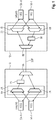
- a single optical fiber SOF connects two SFW-apparatus 1A, 1B with each other.
- An SFW-apparatus can exchange bidirectly data via the SOF fiber.
- a number of transponders can be connected as illustrated in Fig. 1 .
- both apparatuses 1A, 1B comprise a 75 GHz AWG (Arrayed Waveguide Grating) forming part of the optical transponder interface 2 of the apparatuses 1A, 1B.
- a first AWG 6A can be used as a multiplexer and a second AWG 7A can be used as a demultiplexer.
- a first AWG 6A can be used as a multiplexer
- a second AWG 7A can be used as a demultiplexer.
- the WDM data channels of the transponder frequency grid having frequency gaps between the WDM data channels are shifted by a wavelength shifter 3A to avoid a spectral overlap between the Tx WDM data channels received from the transmit ports of the transponders 5A-i and the Rx WDM data channels received by the receive ports of the transponders 5A-i.
- the Tx WDM data channels and the Rx WDM data channels transport data through the single optical fiber SOF in opposite directions.
- the wavelength shifter 3A may shift the Tx WDM data channels by 37.5 GHz, i.e. half the frequency gap between the WDM Tx data channels as also shown as signal spectrum SS2 in Fig. 7 .
- the frequency shifted Tx WDM data channels which have been frequency shifted by the frequency shifter 3A of the SFW-apparatus 1A are combined by an optical combiner 4A of the SFW-apparatus 1A with the frequency shifted Rx WDM data channels to provide a frequency spectrum SS3 as shown in Fig. 7 forming a fiber frequency grid without frequency gaps between the WDM data channels, i.e. the WDM Tx data channels and the WDM Rx data channels, on the single optical fiber SOF.
- the combiner can comprise a 37.5 GHz interleaver. In the system shown in Fig.
- the SFW-apparatus 1B on the other side of the single optical fiber SOF has the same structure as the SFW-apparatus 1A.
- the SFW-apparatus 1B comprises an AFW multiplexer 6B, an AFW demultiplexer 7B, a frequency shifter 3B and an optical combiner 4B.
- the frequency shifter 3B can also perform a wavelength or frequency shift of e.g. 37.5 GHz in the illustrated implementation.
- the optical combiner 4B comprises in a possible embodiment a 37.5 GHz interleaver.
- the transmit and receive ports of the transponders 5-i can be multiplexed independently in 75 GHz AWGs to form a signal spectrum SS1 as shown in Fig. 7 .
- the signals can be fed in a possible embodiment to a polarization diverse frequency shifter 3A.
- all Tx WDM data channels are frequency shifted simultaneously to avoid a spectral overlap between the Tx WDM data channels and the Rx WDM data channels on the single optical fiber SOF.
- the WDM data channels are frequency shifted with half the channel's spacing, e.g. 37.5 GHz. This can be performed by the polarization diverse frequency shifter 3A as shown in Fig. 7 .
- the WDM data channels are shifted from ongrid to offgrid.
- the second signal spectrum SS2 shown in Fig. 7 shows the frequency shifted Tx WDM data channels shifted by 37.5 GHz, i.e. half the channel's spacing of the signal spectrum SS1.
- the Tx and Rx data streams are merged together by a combiner with a 37.5 GHz interleaver resulting in a spectrum SS3 as shown in Fig. 7 .
- This frequency spectrum SS3 forms a fiber frequency grid without frequency gaps between the WDM data channels on the single optical fiber SOF. Accordingly, the Tx WDM data channels and the Rx WDM data channels are located next to each other.
- 64 100G+ transponders 5-i can be multiplexed together in a C-band occupying 128 WDM data channels at a 37.5 GHz grid.
- the optical signal can be demultiplexed and frequency shifted again.
- no further shift is performed on the far end side so that the WDM data channels received by the transponders 5B-i are offgrid.
- the embodiment illustrated in Fig. 1 has the advantage that only one frequency shift is performed, however, it has the disadvantage that the transponders on the other remote side have to operate offgrid. By performing only one frequency shift on the transmission side, using the frequency shifter 3A, the penalty of the frequency shift is minimized.
- This penalty can comprise non-linear signal distortions and/or a noise penalty and/or linear signal distortion and/or spectral attenuation. Accordingly, to minimize the impact of the frequency shifting, only one frequency shifter is used per direction as illustrated in the embodiment of Fig. 1 , 7 . In both directions of the system shown in Fig. 1 , a frequency shifter 3A, 3B is located at the transmit side. With the illustrated configuration of Fig. 1 , both directions comprise one frequency shifter resulting in a more equal performance in both directions.
- a disadvantage of the architecture illustrated in Fig. 1 is that it is more difficult to manage the system as the transponders on the different sides of the single optical fiber SOF operate at different frequency grids spaced e.g.
- the WDM channels on the left side of Fig. 1 connected to the SFW-apparatus 1A may operate ongrid whereas the WDM channels on the right side of Fig 1 connected to SFW-apparatus 1B are offgrid.
- the Tx WDM data channels can be frequency upshifted by a first frequency shifter 3A on a transmission side of the single optical fiber SOF to avoid spectral overlap between the Tx WDM data channels and the Rx WDM data channels.
- the Tx WDM data channels can be frequency upshifted positively with a predetermined frequency shift by a first frequency shifter 3A on the transmission side of the single optical fiber SOF and then frequency downshifted back negatively with the same frequency shift by a second frequency shifter 3B on the reception side of the single optical fiber SOF.
- the first frequency shifter 3A on the transmission side performs an upshift of the WDM data channels by e.g. 37.5 GHz.
- the second frequency shifter 3B on the reception side performs a downshift by the same frequency shift by e.g. 37.5 GHz.
- the advantage of the embodiment illustrated in Fig. 2 is that the transponders 5 on both sides of the single optical fiber SOF use the same frequency grid (ongrid). This simplifies the management of the optical system significantly.
- both the Tx WDM data channels and the Rx WDM data channels are frequency shifted relative to each other by a first frequency shifter 3A on a transmission side of a single optical fiber SOF and by a second frequency shifter 3B on a reception side of a single optical fiber SOF.
- both SFW-apparatuses 1A, 1B comprise two frequency shifters, i.e. a first frequency shifter 3A for performing a positive frequency shift of the Tx WDM data channels and a negative frequency shift of the received WDM data channels.
- a first frequency shifter 3A for performing a positive frequency shift of the Tx WDM data channels and a negative frequency shift of the received WDM data channels.
- the first positive frequency shifter 3A1 of the SFW-apparatus 1A performs a positive wavelength or frequency shift by 18.75 GHz, i.e. a quarter of the 75 GHz spacing of the original signal spectrum.
- the SFW-apparatus 1A further comprises a second negative frequency shifter 3A2 for performing a negative frequency shift of 18.75 GHz of the received Rx WDM data channels.
- the SFW-apparatus 1B on the remote side has the same structure comprising a negative frequency shifter 3B2 and a positive frequency shifter 3B1.
- the negative frequency shifter 3B2 performs a negative frequency shift of 18.75 GHz whereas the positive frequency shifter 3B1 performs a positive frequency shift of also 18.75 GHz in a possible embodiment.
- each SFW-apparatus 1 comprises a positive shifter and a negative frequency shifter.
- the transmission system as illustrated in the embodiments of Figs. 1 , 2 , 3 is configured to operate over a complete C-band with sufficient efficiency.
- the frequency shift can be performed in a possible embodiment by four-wave mixing FWM in a highly non-linear fiber HNLF.
- the main challenge of FWM in HNLF is that HNLF is bulky and that high optical powers are required for FWM generation. Similar high powers are required for Chi2 in a PPLN (Periodically Poled Lithium Niobate).
- PPLN forms a fragile device that needs to be heated. Accordingly, in a preferred embodiment, an IQ Mach-Zehnder modulator can be used for frequency shifting.
- the frequency shift of the signal spectrum of one of the two opposite signal transport directions with half of the channel grid is performed before combining the channels.
- the Tx and Rx WDM data channels are interleaved and are provided at the respective other side where the WDM data channels are converted back for detection.
- the architecture according to the present invention comprises a significant lower complexity than a system using separate local oscillators for each transponder. Further, high-density transmission systems have demanding space and power consumption requirements. Saving the need for a local oscillator eases the space and power requirements of the signal transport system. Further, most transmission systems are DFW systems and as such it is efficient to provide a separate transponder architecture for single fiber-working SFW.
- standard DFW transponders can be used on a single fiber-working, SFW, optical network.
- the method according to the present invention has the further advantage that it is completely independent of the modulation format, protocol and used data rates. Accordingly, the system implementing the method according to the present invention can be used for many generations of transponders.
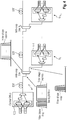
- Fig. 4 shows a schematic diagram for illustrating a possible application of the method and apparatus according to the present invention.
- the method and apparatus according to the present invention allows point-to-point communication from a point P to a point Q in a network.
- the SFW-apparatus 1 according to the present invention is located in a central office and can be connected via a single optical fiber SOF to other points Q1...Qn by means of associated add drop sites.
- the signal spectrum at the add drop site is illustrated in Fig. 4 as well.
- Fig. 5 shows a further use case for implementing the method and apparatus 1 according to the present invention.
- the method can be used for connecting a central office with other nodes in a ring network.
- Each network node comprises at least one SFW-apparatus 1 connected by means of an add drop site as shown in Fig. 5 .
- the frequency shifting performed by the frequency shift units within the different SFW-apparatuses can be controlled by a network management system, for instance by means of a DCN (Dynamic Circuit Network) connection.
- the method and apparatus 1 according to the present invention can be used for a hub and spoke ring network or for linear add drop networks.
- the number of WDM channels and the spacing in the frequency's grid can vary depending on the use case.
Landscapes
- Engineering & Computer Science (AREA)
- Computer Networks & Wireless Communication (AREA)
- Signal Processing (AREA)
- Physics & Mathematics (AREA)
- Electromagnetism (AREA)
- Nonlinear Science (AREA)
- Spectroscopy & Molecular Physics (AREA)
- Optical Communication System (AREA)
Abstract
Description
- Single fiber-working, SFW, networks allow to reduce the number of required fibers in a system. Various DWDM and CWDM SFW architectures are available. All conventional SFW architectures have in common that the transmit wavelength is different from the receive wavelength. It is necessary to transmit and receive a signal at a different wavelength because otherwise fiber reflections of the optical fiber can result in severe transmission penalties. This has in particular a negative impact on 100G+ transponders using coherent detection. Because of space and power restrictions, 100G+ transponders use the same laser on the transmission side and reception side. In dual fiber-working systems, this does not pose a restriction on its operation as the transmit and receive wavelength are typically the same. However, in a single fiber-working, SFW, system, the transmit and receive wavelength must be different and as such these 100G+ transponders cannot be used in a single fiber-working architecture.
- Accordingly, it is an object of the present invention to provide a method and an apparatus for enabling a single fiber-working where data is transportable through a single optical fiber SOF which allows the use of dual fiber-working, DFW, transponders.
- This object is achieved according to a first aspect of the present invention by a method for transporting data through a single fiber, SOF, comprising the features of
claim 1. - The invention provides according to the first aspect of the present invention a method for transporting data through a single optical fiber, SOF, comprising the steps of:
- providing transmission wavelength division multiplexed data channels and reception wavelength division multiplexed data channels having the same frequency grid with frequency gaps between the WDM data channels,
- frequency shifting the transmission wavelength division multiplexed data channels and/or the reception wavelength division multiplexed data channels to avoid spectral overlap between the transmission wavelength division multiplexed data channels and the reception wavelength division multiplexed data channels,
- combining the frequency shifted transmission wavelength division multiplexed data channels and the frequency shifted reception wavelength division multiplexed data channels and transporting data via the combined wavelength division multiplexed data channels through said single optical fiber in opposite directions.
- In a possible embodiment of the method according to the first aspect of the present invention, the transmission wavelength division multiplexed data channels and the reception wavelength division multiplexed data channels are frequency shifted with a frequency shift of at least the Nyquist spectral bandwidth of the respective WDM data channels.
- In a further possible embodiment of the method according to the first aspect of the present invention, the frequency shifted transmission wavelength division multiplexed data channels and the frequency shifted reception wavelength division multiplexed data channels are combined by interleaving the frequency shifted transmission wavelength division multiplexed data channels and the frequency shifted reception wavelength division multiplexed data channels.
- In a further possible embodiment of the method according to the first aspect of the present invention, the frequency shifted transmission wavelength division multiplexed data channels and the frequency shifted reception wavelength division multiplexed data channels are combined by coupling the frequency shifted transmission wavelength division multiplexed data channels and the frequency shifted reception wavelength division multiplexed data channels by means of a passive optical interleaver or a passive optical coupler.
- In a further possible embodiment of the method according to the first aspect of the present invention, all transmission wavelength division multiplexed data channels and/or all reception wavelength division multiplexed data channels are frequency shifted simultaneously to avoid spectral overlap between the transmission wavelength division multiplexed data channels and the reception wavelength division multiplexed data channels on said single optical fiber.
- In a further possible embodiment of the method according to the first aspect of the present invention, the transmission wavelength division multiplexed data channels and the reception wavelength division multiplexed data channels are frequency shifted by a frequency shifter.
- In a still further possible embodiment of the method according to the first aspect of the present invention, the transmission wavelength division multiplexed data channels are frequency upshifted by a frequency shifter on a transmission side of the single optical fiber to avoid spectral overlap between the transmission wavelength division multiplexed data channels and the reception wavelength division multiplexed data channels.
- In a still further possible embodiment of the method according to the first aspect of the present invention, the transmission wavelength division multiplexed data channels are frequency upshifted positively with a frequency shift by a first frequency shifter on a transmission side of said single optical fiber and frequency downshifted back negatively with the same frequency shift by a second frequency shifter on the reception side of said single optical fiber.
- In a still further possible embodiment of the method according to the first aspect of the present invention, both the transmission wavelength division multiplexed data channels and the reception wavelength division multiplexed data channels are frequency shifted relative to each other by a first frequency shifter on a transmission side of said single optical fiber and by a second frequency shifter on a reception side of said single optical fiber.
- In a still further possible embodiment of the method according to the first aspect of the present invention, the frequency shift is realized by an IQ Mach-Zehnder modulator.
- In a further possible alternative embodiment of the method according to the first aspect of the present invention, the frequency shift is realized by four-wave mixing in a highly non-linear fiber.
- In a still further possible embodiment of the method according to the first aspect of the present invention, the frequency shift is realized by cascaded frequency shifting using a Chi2 non-linearity in periodically poled lithium niobate.
- In a further possible embodiment of the method according to the first aspect of the present invention, the frequency shift is adjusted in response to a control signal received from a network management system.
- In a still further possible embodiment of the method according to the first aspect of the present invention, the transmission wavelength division multiplexed data channels are provided by transmit ports of multiple transponders and multiplexed or coupled to provide a first frequency spectrum forming a transponder frequency grid with frequency gaps between the transmission wavelength division multiplexed data channels.
- In a further possible embodiment of the method according to the first aspect of the present invention, the frequency shifted transmission wavelength division multiplexed data channels and the frequency shifted reception wavelength division multiplexed data channels are combined to provide a second frequency spectrum forming a fiber frequency grid without frequency gaps between the wavelength division multiplexed data channels on said single optical fiber.
- In a further possible embodiment of the method according to the first aspect of the present invention, a frequency distance between two adjacent transmission wavelength division multiplexed data channels in the first frequency spectrum is at least twice the frequency distance between a transmission wavelength division multiplexed data channel and a reception wavelength division multiplexed data channel in the second signal spectrum on the single optical fiber.
- The invention further provides according to a further aspect a SFW-apparatus for enabling a single fiber-working, SFW, where data is transportable through a single optical fiber, SOF, said SFW-apparatus comprising:
- an optical transponder interface adapted to provide transmission wavelength division multiplexed data channels and reception wavelength division multiplexed data channels having the same frequency grid with frequency gaps between the WDM data channels,
- a frequency shifter adapted to perform frequency shifting on the transmission wavelength division multiplexed data channels and/or the reception wavelength division multiplexed data channels to avoid a spectral overlap between the transmission wavelength division multiplexed data channels and the reception wavelength division multiplexed data channels, and an optical combiner adapted to combine the frequency shifted transmission wavelength division multiplexed data channels and the frequency shifted reception wavelength division multiplexed data channels for the single optical fiber.
- In a possible embodiment of the SFW-apparatus according to the second aspect of the present invention, the frequency shift is realized by an IQ Mach-Zehnder modulator, by four-wave mixing in a highly non-linear fiber and/or by cascaded frequency shifting using Chi2 non-linearity in periodically poled lithium niobate.
- The invention further provides according to a third aspect an optical network comprising network nodes connected to each other via a single optical fiber, SOF, wherein each network node of said optical network comprises an SFW-apparatus according to the second aspect of the present invention.
- In the following, embodiments of the different aspects of the present invention are described in more detail with reference to the enclosed figures.
- Fig. 1
- shows a diagram for illustrating a first possible embodiment of an SFW-apparatus for enabling a single fiber-working according to an aspect of the present invention;
- Fig. 2
- shows a further diagram for illustrating a further possible exemplary embodiment of an SFW-apparatus for enabling a single fiber-working according to an aspect of the present invention;
- Fig. 3
- shows a further diagram for illustrating an exemplary embodiment of an SFW-apparatus for enabling a single fiber-working according to an aspect of the present invention;
- Fig. 4
- shows a further circuit diagram for illustrating a possible exemplary embodiment of a system using an SFW-apparatus in a point-to-point connection;
- Fig. 5
- illustrates a circuit diagram of a system using an SFW-apparatus in a ring network;
- Fig. 6
- shows a schematic block diagram of a possible exemplary embodiment of an SFW-apparatus according to an aspect of the present invention;
- Fig. 7
- shows a flowchart of an exemplary embodiment of a method for transporting data through a single optical fiber according to an aspect of the present invention.
- The method for transporting data through a single optical fiber SOF performed by a method according to the present invention comprises several main steps. As illustrated in
Fig. 7 , the method can comprise in a possible embodiment four main steps S1, S2, S3, S4. - In a first step S1, transmission, Tx, wavelength division multiplexed, WDM, data channels are provided as well as reception, Rx, wavelength division multiplexed, WDM, data channels having the same frequency grid with frequency gaps between the WDM data channels as also shown in
Fig. 1 of the illustrated embodiment of the SFW-apparatus 1. - In a further step S2 as shown in the flowchart of
Fig. 7 , the Tx WDM data channels and/or the Rx WDM data channels are frequency shifted to avoid a spectral overlap between the transmission WDM data channels and the Rx WDM data channels. A frequency shift can be realized in different ways. In a possible embodiment, the frequency shift can be realized by an IQ Mach-Zehnder modulator. In an alternative embodiment, the frequency shift is realized by four-wave mixing in a highly non-linear fiber. In a still further alternative embodiment, the frequency shift can be realized by cascaded frequency shifting using a Chi2 non-linearity in periodically poled lithium niobate. In a possible embodiment, the frequency shift can be performed in response to a control signal received from a network management system. In a possible embodiment, the transmission wavelength division multiplexed data channels and the reception wavelength division multiplexed data channels can be frequency shifted by a frequency shift of at least the Nyquist spectral bandwidth of the respective WDM data channels. - In a further step S3 as shown in the flowchart of
Fig. 7 , the frequency shifted transmission wavelength division multiplexed data channels and the frequency shifted reception wavelength division multiplexed data channels are combined. In a possible embodiment, the frequency shifted Tx WDM data channels and the frequency shifted Rx WDM data channels are combined by interleaving the frequency shifted transmission wavelength division multiplexed data channels and the frequency shifted reception wavelength division multiplexed data channels. The frequency shifted Tx WDM data channels and the frequency shifted Rx WDM data channels can be combined by coupling the frequency shifted Tx WDM data channels and the frequency shifted Rx WDM data channels by means of a passive optical interleaver or by means of a passive optical coupler. - After having combined the frequency shifted Tx WDM data channels and the frequency shifted Rx WDM data channels in step S3, data is transported via the combined WDM data channels in opposite directions through the single optical fiber SOF in step S4 as illustrated in
Fig. 7 (signal spectrum SS3). - In a possible embodiment, the single fiber-working, SFW,
apparatus 1 according to an aspect of the present invention enables a single fiber-working SFW where data is transportable through a single optical fiber SOF which can be connected to conventional transponders, in particular to dual fiber-working, DFW, 100G+ transponders as illustrated in the embodiments shown inFigs. 1 to 5 . - As shown in the block diagram of
Fig. 6 , an SFW-apparatus 1 for enabling single fiber-working, SFW, according to an aspect of the present invention can comprise in the illustrated embodiment three main units. The SFW-apparatus 1 comprises in the illustrated embodiment ofFig. 6 anoptical transponder interface 2, afrequency shifter 3 and anoptical combiner 4. - The
optical transponder interface 2 is adapted to provide transmission, Tx, wavelength division multiplexed, WDM, data channels and reception, Rx, wavelength division multiplexed, WDM, data channels having the same frequency grid with frequency gaps between the WDM data channels. - The
frequency shifter 3 of the SFW-apparatus 1 as shown inFig. 6 is adapted to perform frequency shifting of the Tx WDM data channels and/or the Rx WDM data channels to avoid a spectral overlap between the Tx WDM data channels and the Rx WDM data channels. - The SFW-
apparatus 1 further comprises in the illustrated embodiment anoptical combiner 4 adapted to combine the frequency shifted Tx WDM data channels and the frequency shifted Rx WDM data channels for the single optical fiber, SOF, as shown inFig. 6 . - The
optical transponder interface 2 of the SFW-apparatus 1 can be connected to a number of transponders 5-1, 5-2 ... 5-n as shown inFig. 6 . The number of transponders 5-i connectable to the optical transponder interface can vary. In a possible embodiment, the transponders 5-i compriseDFW 100G transponders. - The Tx WDM data channels are provided by transmit ports of the multiple transponders 5-i and are multiplexed or coupled to provide a first frequency spectrum forming a transponder frequency grid with frequency gaps between the transmission wavelength division multiplexed data channels. Accordingly, at the
optical transponder interface 2, the Tx WDM data channels comprise a transponder frequency grid with frequency gaps between the Tx WDM data channels. In the illustrated example ofFig. 1 , the transponder frequency grid comprises frequency gaps with a 75 GHz spacing between the transmission WDM data channels as also illustrated as signal spectrum SS1 inFig. 7 . Other spacings are possible, e.g. 50 GHz spacings between the data channels. The transmission wavelength division multiplexed data channels with multiple transponders can be multiplexed or coupled to provide a first frequency spectrum (ongrid) with sufficient frequency gaps between the transmission WDM data channels. - In the illustrated system of
Fig. 1 , a single optical fiber SOF connects two SFW-apparatus apparatuses Fig. 1 . In the illustrated embodiment ofFig. 1 , bothapparatuses optical transponder interface 2 of theapparatuses first AWG 6A can be used as a multiplexer and asecond AWG 7A can be used as a demultiplexer. In the illustrated embodiment ofFig. 1 , the WDM data channels of the transponder frequency grid having frequency gaps between the WDM data channels are shifted by awavelength shifter 3A to avoid a spectral overlap between the Tx WDM data channels received from the transmit ports of thetransponders 5A-i and the Rx WDM data channels received by the receive ports of thetransponders 5A-i. The Tx WDM data channels and the Rx WDM data channels transport data through the single optical fiber SOF in opposite directions. In a possible embodiment, thewavelength shifter 3A may shift the Tx WDM data channels by 37.5 GHz, i.e. half the frequency gap between the WDM Tx data channels as also shown as signal spectrum SS2 inFig. 7 . Then, the frequency shifted Tx WDM data channels which have been frequency shifted by thefrequency shifter 3A of the SFW-apparatus 1A are combined by anoptical combiner 4A of the SFW-apparatus 1A with the frequency shifted Rx WDM data channels to provide a frequency spectrum SS3 as shown inFig. 7 forming a fiber frequency grid without frequency gaps between the WDM data channels, i.e. the WDM Tx data channels and the WDM Rx data channels, on the single optical fiber SOF. In a possible implementation, the combiner can comprise a 37.5 GHz interleaver. In the system shown inFig. 1 , the SFW-apparatus 1B on the other side of the single optical fiber SOF has the same structure as the SFW-apparatus 1A. The SFW-apparatus 1B comprises anAFW multiplexer 6B, anAFW demultiplexer 7B, afrequency shifter 3B and anoptical combiner 4B. Thefrequency shifter 3B can also perform a wavelength or frequency shift of e.g. 37.5 GHz in the illustrated implementation. Theoptical combiner 4B comprises in a possible embodiment a 37.5 GHz interleaver. - In the illustrated embodiment of
Fig. 1 ,7 the transmit and receive ports of the transponders 5-i can be multiplexed independently in 75 GHz AWGs to form a signal spectrum SS1 as shown inFig. 7 . The signals can be fed in a possible embodiment to a polarizationdiverse frequency shifter 3A. In a possible embodiment, all Tx WDM data channels are frequency shifted simultaneously to avoid a spectral overlap between the Tx WDM data channels and the Rx WDM data channels on the single optical fiber SOF. In a possible embodiment, the WDM data channels are frequency shifted with half the channel's spacing, e.g. 37.5 GHz. This can be performed by the polarizationdiverse frequency shifter 3A as shown inFig. 7 . Accordingly, the WDM data channels are shifted from ongrid to offgrid. The second signal spectrum SS2 shown inFig. 7 shows the frequency shifted Tx WDM data channels shifted by 37.5 GHz, i.e. half the channel's spacing of the signal spectrum SS1. Then, the Tx and Rx data streams are merged together by a combiner with a 37.5 GHz interleaver resulting in a spectrum SS3 as shown inFig. 7 . This frequency spectrum SS3 forms a fiber frequency grid without frequency gaps between the WDM data channels on the single optical fiber SOF. Accordingly, the Tx WDM data channels and the Rx WDM data channels are located next to each other. In a possible implementation, 64 100G+ transponders 5-i can be multiplexed together in a C-band occupying 128 WDM data channels at a 37.5 GHz grid. On the far end of the single optical fiber SOF, the optical signal can be demultiplexed and frequency shifted again. In the embodiment shown inFig. 1 , no further shift is performed on the far end side so that the WDM data channels received by thetransponders 5B-i are offgrid. The embodiment illustrated inFig. 1 has the advantage that only one frequency shift is performed, however, it has the disadvantage that the transponders on the other remote side have to operate offgrid. By performing only one frequency shift on the transmission side, using thefrequency shifter 3A, the penalty of the frequency shift is minimized. This penalty can comprise non-linear signal distortions and/or a noise penalty and/or linear signal distortion and/or spectral attenuation. Accordingly, to minimize the impact of the frequency shifting, only one frequency shifter is used per direction as illustrated in the embodiment ofFig. 1 ,7 . In both directions of the system shown inFig. 1 , afrequency shifter Fig. 1 , both directions comprise one frequency shifter resulting in a more equal performance in both directions. However, a disadvantage of the architecture illustrated inFig. 1 is that it is more difficult to manage the system as the transponders on the different sides of the single optical fiber SOF operate at different frequency grids spaced e.g. by 37.5 GHZ apart. The WDM channels on the left side ofFig. 1 connected to the SFW-apparatus 1A may operate ongrid whereas the WDM channels on the right side ofFig 1 connected to SFW-apparatus 1B are offgrid. - In a further possible embodiment, the Tx WDM data channels can be frequency upshifted by a
first frequency shifter 3A on a transmission side of the single optical fiber SOF to avoid spectral overlap between the Tx WDM data channels and the Rx WDM data channels. The Tx WDM data channels can be frequency upshifted positively with a predetermined frequency shift by afirst frequency shifter 3A on the transmission side of the single optical fiber SOF and then frequency downshifted back negatively with the same frequency shift by asecond frequency shifter 3B on the reception side of the single optical fiber SOF. This embodiment is illustrated inFig. 2 . Thefirst frequency shifter 3A on the transmission side performs an upshift of the WDM data channels by e.g. 37.5 GHz. - The
second frequency shifter 3B on the reception side performs a downshift by the same frequency shift by e.g. 37.5 GHz. The advantage of the embodiment illustrated inFig. 2 is that thetransponders 5 on both sides of the single optical fiber SOF use the same frequency grid (ongrid). This simplifies the management of the optical system significantly. - In a further possible embodiment, both the Tx WDM data channels and the Rx WDM data channels are frequency shifted relative to each other by a
first frequency shifter 3A on a transmission side of a single optical fiber SOF and by asecond frequency shifter 3B on a reception side of a single optical fiber SOF. In the illustrated embodiment of the system shown inFig. 3 , both SFW-apparatuses first frequency shifter 3A for performing a positive frequency shift of the Tx WDM data channels and a negative frequency shift of the received WDM data channels. In the illustrated implementation ofFig. 3 , the first positive frequency shifter 3A1 of the SFW-apparatus 1A performs a positive wavelength or frequency shift by 18.75 GHz, i.e. a quarter of the 75 GHz spacing of the original signal spectrum. The SFW-apparatus 1A further comprises a second negative frequency shifter 3A2 for performing a negative frequency shift of 18.75 GHz of the received Rx WDM data channels. The SFW-apparatus 1B on the remote side has the same structure comprising a negative frequency shifter 3B2 and a positive frequency shifter 3B1. The negative frequency shifter 3B2 performs a negative frequency shift of 18.75 GHz whereas the positive frequency shifter 3B1 performs a positive frequency shift of also 18.75 GHz in a possible embodiment. The embodiment shown inFig. 3 has the advantage that the frequency shift itself is minimized. Further, since the transponders on both sides work ongrid, the management is simplified. However, the system ofFig. 3 requires a higher technical complexity since each SFW-apparatus 1 comprises a positive shifter and a negative frequency shifter. - In a possible embodiment, the transmission system as illustrated in the embodiments of
Figs. 1 ,2 ,3 is configured to operate over a complete C-band with sufficient efficiency. The frequency shift can be performed in a possible embodiment by four-wave mixing FWM in a highly non-linear fiber HNLF. The main challenge of FWM in HNLF is that HNLF is bulky and that high optical powers are required for FWM generation. Similar high powers are required for Chi2 in a PPLN (Periodically Poled Lithium Niobate). In addition, PPLN forms a fragile device that needs to be heated. Accordingly, in a preferred embodiment, an IQ Mach-Zehnder modulator can be used for frequency shifting. - In the system according to the present invention, the frequency shift of the signal spectrum of one of the two opposite signal transport directions with half of the channel grid is performed before combining the channels. Thereby, the Tx and Rx WDM data channels are interleaved and are provided at the respective other side where the WDM data channels are converted back for detection. The architecture according to the present invention comprises a significant lower complexity than a system using separate local oscillators for each transponder. Further, high-density transmission systems have demanding space and power consumption requirements. Saving the need for a local oscillator eases the space and power requirements of the signal transport system. Further, most transmission systems are DFW systems and as such it is efficient to provide a separate transponder architecture for single fiber-working SFW. With the method according to the present invention, standard DFW transponders can be used on a single fiber-working, SFW, optical network. The method according to the present invention has the further advantage that it is completely independent of the modulation format, protocol and used data rates. Accordingly, the system implementing the method according to the present invention can be used for many generations of transponders.
-
Fig. 4 shows a schematic diagram for illustrating a possible application of the method and apparatus according to the present invention. The method and apparatus according to the present invention allows point-to-point communication from a point P to a point Q in a network. In the illustrated embodiment, the SFW-apparatus 1 according to the present invention is located in a central office and can be connected via a single optical fiber SOF to other points Q1...Qn by means of associated add drop sites. The signal spectrum at the add drop site is illustrated inFig. 4 as well. -
Fig. 5 shows a further use case for implementing the method andapparatus 1 according to the present invention. In the illustrated embodiment, the method can be used for connecting a central office with other nodes in a ring network. Each network node comprises at least one SFW-apparatus 1 connected by means of an add drop site as shown inFig. 5 . - In a possible embodiment of an optical network, the frequency shifting performed by the frequency shift units within the different SFW-apparatuses can be controlled by a network management system, for instance by means of a DCN (Dynamic Circuit Network) connection. The method and
apparatus 1 according to the present invention can be used for a hub and spoke ring network or for linear add drop networks. The number of WDM channels and the spacing in the frequency's grid can vary depending on the use case. -
- 1, 1A, 1 B SFW apparatus
- 2, 2a, 2B transponder interfaces
- 3, 3A, 3B frequency shifter
- 4, 4A, 4B optical combiner
- 5, 5A, 5B transponder
- 6A, 6B Arrayed waveguide grating AWG
- 7A, 7B Arrayed waveguide grating AWG
Claims (17)
- A method for transporting data through a single optical fiber (SOF) the method comprising the steps of:(a) providing (S1) transmission Tx, wavelength division multiplexed, WDM, data channels and reception Rx, wavelength division multiplexed, WDM, data channels having the same frequency grid with frequency gaps between the WDM data channels;(b) frequency shifting (S2) the Tx-WDM data channels and/or the Rx-WDM data channels to avoid spectral overlap between the Tx-WDM data channels and the Rx-WDM data channels;(c) combining (S3) the frequency shifted Tx-WDM data channels and the frequency shifted Rx-WDM data channels; and(d) transporting (S4) data via the combined WDM data channels through said single optical fiber (SOF) in opposite directions.
- The method according to claim 1 wherein the Tx-WDM data channels and the Rx-WDM data channels are frequency shifted with a frequency shift of at least the Nyquist spectral bandwidth of the respective WDM data channels.
- The method according to claim 1 or 2 wherein the frequency shifted Tx-WDM data channels and the frequency shifted Rx-WDM data channels are combined (S3) by interleaving the frequency shifted Tx-WDM data channels and the frequency shifted Rx-WDM data channels.
- The method according to claim 3 wherein the frequency shifted Tx-WDM data channels and the frequency shifted Rx-WDM data channels are combined (S3) by coupling the frequency shifted Tx-WDM data channels and the frequency shifted Rx-WDM data channels by means of a passive optical interleaver or a passive optical coupler.
- The method according to any of the preceding claims 1 to 4 wherein all Tx-WDM data channels and/or all Rx-WDM data channels are frequency shifted (S2) simultaneously to avoid spectral overlap between the Tx-WDM data channels and the Rx-WDM data channels on said single optical fiber (SOF).
- The method according to any of the preceding claims 1 to 5 wherein the Tx-WDM data channels and the Rx-WDM data channels are frequency shifted (S2) by a frequency shifter.
- The method according to any of the preceding claims 1 to 6 wherein the Tx-WDM data channels are frequency upshifted by a frequency shifter on a transmission side of the single optical fiber (SOF) to avoid spectral overlap between the Tx-WDM data channels and the Rx-WDM data channels.
- The method according to any of the preceding claims 1 to 7 wherein the Tx-WDM data channels are frequency upshifted positively with a frequency shift by a first frequency shifter on a transmission side of said single optical fiber (SOF) and frequency downshifted back negatively with the same frequency shift by a second frequency shifter on the reception side of said single optical fiber (SOF).
- The method according to any of the preceding claims 1 to 6 wherein both the Tx-WDM data channels and the Rx-WDM data channels are frequency shifted relative to each other by a first frequency shifter on a transmission side of said single optical fiber (SOF) and by a second frequency shifter on a reception side of said single optical fiber (SOF).
- The method according to any of the preceding claims 1 to 9 wherein the frequency shift is realized by an IQ Mach-Zehnder modulator,
by four-wave mixing in a highly non-linear fiber and/or by cascaded frequency shifting using a Chi2 non-linearity in periodically poled lithium niobate. - The method according to any of the preceding claims 1 to 10 wherein the frequency shift is adjusted in response to a control signal received from a network management system.
- The method according to any of the preceding claims 1 to 11 wherein the Tx-WDM data channels are provided by transmit ports of multiple transponders and multiplexed or coupled to provide a first frequency spectrum forming a transponder frequency grid with frequency gaps between the Tx-WDM data channels.
- The method according to any of the preceding claims 1 to 12 wherein the frequency shifted Tx-WDM data channels and the frequency shifted Rx-WDM data channels are combined to provide a second frequency spectrum forming a fiber frequency grid without frequency gaps between the WDM data channels on said single optical fiber (SOF).
- The method according to claim 13 wherein a frequency distance between two adjacent Tx-WDM data channels in said first frequency spectrum is at least twice the frequency distance between a Tx-WDM data channel and an Rx-WDM data channel in said second signal spectrum on said single optical fiber (SOF).
- An SFW-apparatus for enabling a single fiber working, SFW, where data is transportable through a single optical fiber (SOF),
said SFW-apparatus (1) comprising:(a) an optical transponder interface (2) adapted to provide transmission, Tx, wavelength division multiplexed, WDM, data channels and reception, Rx, wavelength division multiplexed, WDM, data channels having the same frequency grid with frequency gaps between the WDM data channels;(b) a frequency shifter (3) adapted to perform frequency shifting of the Tx-WDM data channels and/or the Rx-WDM data channels to avoid a spectral overlap between the Tx-WDM data channels and the Rx-WDM data channels;(c) an optical combiner (4) adapted to combine the frequency shifted Tx-WDM data channels and the frequency shifted Rx-WDM data channels for the single optical fiber (SOF). - The SFW-apparatus according to claim 15 wherein the frequency shift is realized by an IQ Mach-Zehnder modulator, by four-wave mixing in a highly non-linear fiber and/or by cascaded frequency shifting using Chi2 non-linearity in periodically poled lithium niobate.
- An optical network comprising network nodes connected to each other via a single optical fiber (SOF) wherein each network node of said optical network comprises an SFW-apparatus (1) according to claim 15 or 16.
Priority Applications (2)
| Application Number | Priority Date | Filing Date | Title |
|---|---|---|---|
| EP17181587.1A EP3432494B1 (en) | 2017-07-17 | 2017-07-17 | A method and apparatus for enabling a single fiber-working on an optical fiber |
| US16/024,406 US10615904B2 (en) | 2017-07-17 | 2018-06-29 | Method and apparatus for enabling a single fiber-working on an optical fiber |
Applications Claiming Priority (1)
| Application Number | Priority Date | Filing Date | Title |
|---|---|---|---|
| EP17181587.1A EP3432494B1 (en) | 2017-07-17 | 2017-07-17 | A method and apparatus for enabling a single fiber-working on an optical fiber |
Publications (2)
| Publication Number | Publication Date |
|---|---|
| EP3432494A1 true EP3432494A1 (en) | 2019-01-23 |
| EP3432494B1 EP3432494B1 (en) | 2021-09-08 |
Family
ID=59381075
Family Applications (1)
| Application Number | Title | Priority Date | Filing Date |
|---|---|---|---|
| EP17181587.1A Active EP3432494B1 (en) | 2017-07-17 | 2017-07-17 | A method and apparatus for enabling a single fiber-working on an optical fiber |
Country Status (2)
| Country | Link |
|---|---|
| US (1) | US10615904B2 (en) |
| EP (1) | EP3432494B1 (en) |
Families Citing this family (1)
| Publication number | Priority date | Publication date | Assignee | Title |
|---|---|---|---|---|
| CN119232270B (en) * | 2024-12-04 | 2025-02-14 | 中国科学院国家授时中心 | A distributed fiber optic frequency transmission method and system |
Citations (3)
| Publication number | Priority date | Publication date | Assignee | Title |
|---|---|---|---|---|
| WO2012110081A1 (en) * | 2011-02-15 | 2012-08-23 | Nokia Siemens Networks Oy | Processing data in an optical network |
| US20130315598A1 (en) * | 2012-04-25 | 2013-11-28 | Yissum Research Development Company of the Hebrew University of Jerusalem Ltd. | System and method for use in wavelength division multiplexer |
| US20150304036A1 (en) * | 2014-04-17 | 2015-10-22 | Nec Laboratories America, Inc. | Interleaved Bidirectional Sub-Nyquist Transmission with Overlapping Counter-Propagating Signal Spectral Bands |
Family Cites Families (15)
| Publication number | Priority date | Publication date | Assignee | Title |
|---|---|---|---|---|
| JPH0712230B2 (en) * | 1988-07-18 | 1995-02-08 | 富士通株式会社 | Optical switching system |
| US5619368A (en) * | 1995-05-16 | 1997-04-08 | Massachusetts Inst. Of Technology | Optical frequency shifter |
| US6359725B1 (en) * | 1998-06-16 | 2002-03-19 | Xtera Communications, Inc. | Multi-stage optical amplifier and broadband communication system |
| GB0121492D0 (en) * | 2001-09-05 | 2001-10-24 | Cit Alcatel | A multi-channel optical loading channel transmitter |
| EP2186236A1 (en) * | 2007-08-30 | 2010-05-19 | Telefonaktiebolaget LM Ericsson (PUBL) | Improvements in or relating to multicarrier communication |
| US20090060497A1 (en) * | 2007-08-30 | 2009-03-05 | Way Winston I | Feedback Controlled Locking of Optical Channel Signals in Optical Receivers in Wavelength Division Multiplexed (WDM) Communication Systems |
| JP5432389B2 (en) * | 2011-02-16 | 2014-03-05 | 日本電信電話株式会社 | Optical frequency shifter and optical modulator using the same |
| JP5760581B2 (en) * | 2011-03-25 | 2015-08-12 | 富士通株式会社 | Multi-wavelength light source |
| EP2573961B1 (en) * | 2011-09-12 | 2016-04-13 | ADVA Optical Networking SE | An optical frequency locking method and device for optical data transmission |
| EP2907250B1 (en) * | 2012-10-09 | 2016-12-07 | Telefonaktiebolaget LM Ericsson (publ) | Optical communication system, method of bi-directional communication and method of operating a network element |
| US9100137B2 (en) * | 2013-04-22 | 2015-08-04 | Fujitsu Limited | Crosstalk reduction in optical networks using variable subcarrier spectral allocation |
| US20150086200A1 (en) * | 2013-09-20 | 2015-03-26 | Alcatel-Lucent Usa Inc. | Space To Wavelength Superchannel Conversion |
| EP2999151B1 (en) * | 2014-09-19 | 2019-06-19 | ADVA Optical Networking SE | Method and communication control device for establishing a communication channel in a communication network |
| US20170214488A1 (en) * | 2016-01-27 | 2017-07-27 | Fujitsu Limited | Superchannels with mixed baud rate subcarriers |
| US10230468B2 (en) * | 2016-06-02 | 2019-03-12 | Huawei Technologies Co., Ltd. | Transmission adjustment for space division multiplexing of optical signals |
-
2017
- 2017-07-17 EP EP17181587.1A patent/EP3432494B1/en active Active
-
2018
- 2018-06-29 US US16/024,406 patent/US10615904B2/en active Active
Patent Citations (3)
| Publication number | Priority date | Publication date | Assignee | Title |
|---|---|---|---|---|
| WO2012110081A1 (en) * | 2011-02-15 | 2012-08-23 | Nokia Siemens Networks Oy | Processing data in an optical network |
| US20130315598A1 (en) * | 2012-04-25 | 2013-11-28 | Yissum Research Development Company of the Hebrew University of Jerusalem Ltd. | System and method for use in wavelength division multiplexer |
| US20150304036A1 (en) * | 2014-04-17 | 2015-10-22 | Nec Laboratories America, Inc. | Interleaved Bidirectional Sub-Nyquist Transmission with Overlapping Counter-Propagating Signal Spectral Bands |
Also Published As
| Publication number | Publication date |
|---|---|
| US20190020437A1 (en) | 2019-01-17 |
| EP3432494B1 (en) | 2021-09-08 |
| US10615904B2 (en) | 2020-04-07 |
Similar Documents
| Publication | Publication Date | Title |
|---|---|---|
| US6810215B1 (en) | Optical repeater converting wavelength and bit rate between networks | |
| JPH04207646A (en) | network | |
| US9742519B2 (en) | Photonic cross-connect with reconfigurable add-drop-functionality | |
| US7110674B2 (en) | Optical add/drop device | |
| CN104661117A (en) | Optical network switching equipment | |
| JP5063558B2 (en) | Optical repeater | |
| US20240056706A1 (en) | Electrical Switching Cluster System | |
| US20160301495A1 (en) | Power Efficient Multi-Degree ROADM Using Variable Optical Splitter | |
| US20260005783A1 (en) | Optical communication system and communication method | |
| JP3439162B2 (en) | Optical wavelength division multiplexing network equipment | |
| US10615904B2 (en) | Method and apparatus for enabling a single fiber-working on an optical fiber | |
| US10261276B2 (en) | Datacenter interconnection system | |
| EP3091678B1 (en) | Optical wdm transmission network | |
| EP1009120A2 (en) | Multichannel optical ADD/DROP, multiplexor/demultiplexor | |
| US20130077976A1 (en) | Transmitter and method for optical transmission | |
| US10484122B2 (en) | Optical add/drop multiplexer and control method thereof, and transceiver | |
| US7305184B2 (en) | Method and system for management of directly connected optical components | |
| EP1123595A2 (en) | Wdm transmitter and receiver | |
| US6845188B2 (en) | DC WDM device and DC WDM system and transmission network using the same | |
| JP2002374209A (en) | Multiplexed optical transmission method and multiplexed optical transmission device | |
| JP5340369B2 (en) | Optical repeater | |
| JP5081726B2 (en) | Optical transmission system | |
| JP3318556B2 (en) | Communication method | |
| JP3286094B2 (en) | Optical WDM Network System | |
| CN118413288A (en) | A wavelength division multiplexing transmission network |
Legal Events
| Date | Code | Title | Description |
|---|---|---|---|
| PUAI | Public reference made under article 153(3) epc to a published international application that has entered the european phase |
Free format text: ORIGINAL CODE: 0009012 |
|
| STAA | Information on the status of an ep patent application or granted ep patent |
Free format text: STATUS: THE APPLICATION HAS BEEN PUBLISHED |
|
| AK | Designated contracting states |
Kind code of ref document: A1 Designated state(s): AL AT BE BG CH CY CZ DE DK EE ES FI FR GB GR HR HU IE IS IT LI LT LU LV MC MK MT NL NO PL PT RO RS SE SI SK SM TR |
|
| AX | Request for extension of the european patent |
Extension state: BA ME |
|
| STAA | Information on the status of an ep patent application or granted ep patent |
Free format text: STATUS: REQUEST FOR EXAMINATION WAS MADE |
|
| 17P | Request for examination filed |
Effective date: 20190418 |
|
| RBV | Designated contracting states (corrected) |
Designated state(s): AL AT BE BG CH CY CZ DE DK EE ES FI FR GB GR HR HU IE IS IT LI LT LU LV MC MK MT NL NO PL PT RO RS SE SI SK SM TR |
|
| STAA | Information on the status of an ep patent application or granted ep patent |
Free format text: STATUS: EXAMINATION IS IN PROGRESS |
|
| 17Q | First examination report despatched |
Effective date: 20200428 |
|
| GRAP | Despatch of communication of intention to grant a patent |
Free format text: ORIGINAL CODE: EPIDOSNIGR1 |
|
| STAA | Information on the status of an ep patent application or granted ep patent |
Free format text: STATUS: GRANT OF PATENT IS INTENDED |
|
| INTG | Intention to grant announced |
Effective date: 20210329 |
|
| GRAS | Grant fee paid |
Free format text: ORIGINAL CODE: EPIDOSNIGR3 |
|
| GRAA | (expected) grant |
Free format text: ORIGINAL CODE: 0009210 |
|
| STAA | Information on the status of an ep patent application or granted ep patent |
Free format text: STATUS: THE PATENT HAS BEEN GRANTED |
|
| AK | Designated contracting states |
Kind code of ref document: B1 Designated state(s): AL AT BE BG CH CY CZ DE DK EE ES FI FR GB GR HR HU IE IS IT LI LT LU LV MC MK MT NL NO PL PT RO RS SE SI SK SM TR |
|
| REG | Reference to a national code |
Ref country code: GB Ref legal event code: FG4D |
|
| REG | Reference to a national code |
Ref country code: CH Ref legal event code: EP Ref country code: AT Ref legal event code: REF Ref document number: 1429516 Country of ref document: AT Kind code of ref document: T Effective date: 20210915 |
|
| REG | Reference to a national code |
Ref country code: DE Ref legal event code: R096 Ref document number: 602017045570 Country of ref document: DE |
|
| REG | Reference to a national code |
Ref country code: IE Ref legal event code: FG4D |
|
| REG | Reference to a national code |
Ref country code: LT Ref legal event code: MG9D |
|
| REG | Reference to a national code |
Ref country code: NL Ref legal event code: MP Effective date: 20210908 |
|
| PG25 | Lapsed in a contracting state [announced via postgrant information from national office to epo] |
Ref country code: BG Free format text: LAPSE BECAUSE OF FAILURE TO SUBMIT A TRANSLATION OF THE DESCRIPTION OR TO PAY THE FEE WITHIN THE PRESCRIBED TIME-LIMIT Effective date: 20211208 Ref country code: LT Free format text: LAPSE BECAUSE OF FAILURE TO SUBMIT A TRANSLATION OF THE DESCRIPTION OR TO PAY THE FEE WITHIN THE PRESCRIBED TIME-LIMIT Effective date: 20210908 Ref country code: ES Free format text: LAPSE BECAUSE OF FAILURE TO SUBMIT A TRANSLATION OF THE DESCRIPTION OR TO PAY THE FEE WITHIN THE PRESCRIBED TIME-LIMIT Effective date: 20210908 Ref country code: FI Free format text: LAPSE BECAUSE OF FAILURE TO SUBMIT A TRANSLATION OF THE DESCRIPTION OR TO PAY THE FEE WITHIN THE PRESCRIBED TIME-LIMIT Effective date: 20210908 Ref country code: HR Free format text: LAPSE BECAUSE OF FAILURE TO SUBMIT A TRANSLATION OF THE DESCRIPTION OR TO PAY THE FEE WITHIN THE PRESCRIBED TIME-LIMIT Effective date: 20210908 Ref country code: NO Free format text: LAPSE BECAUSE OF FAILURE TO SUBMIT A TRANSLATION OF THE DESCRIPTION OR TO PAY THE FEE WITHIN THE PRESCRIBED TIME-LIMIT Effective date: 20211208 Ref country code: SE Free format text: LAPSE BECAUSE OF FAILURE TO SUBMIT A TRANSLATION OF THE DESCRIPTION OR TO PAY THE FEE WITHIN THE PRESCRIBED TIME-LIMIT Effective date: 20210908 Ref country code: RS Free format text: LAPSE BECAUSE OF FAILURE TO SUBMIT A TRANSLATION OF THE DESCRIPTION OR TO PAY THE FEE WITHIN THE PRESCRIBED TIME-LIMIT Effective date: 20210908 |
|
| REG | Reference to a national code |
Ref country code: AT Ref legal event code: MK05 Ref document number: 1429516 Country of ref document: AT Kind code of ref document: T Effective date: 20210908 |
|
| PG25 | Lapsed in a contracting state [announced via postgrant information from national office to epo] |
Ref country code: LV Free format text: LAPSE BECAUSE OF FAILURE TO SUBMIT A TRANSLATION OF THE DESCRIPTION OR TO PAY THE FEE WITHIN THE PRESCRIBED TIME-LIMIT Effective date: 20210908 Ref country code: GR Free format text: LAPSE BECAUSE OF FAILURE TO SUBMIT A TRANSLATION OF THE DESCRIPTION OR TO PAY THE FEE WITHIN THE PRESCRIBED TIME-LIMIT Effective date: 20211209 |
|
| PG25 | Lapsed in a contracting state [announced via postgrant information from national office to epo] |
Ref country code: AT Free format text: LAPSE BECAUSE OF FAILURE TO SUBMIT A TRANSLATION OF THE DESCRIPTION OR TO PAY THE FEE WITHIN THE PRESCRIBED TIME-LIMIT Effective date: 20210908 |
|
| PG25 | Lapsed in a contracting state [announced via postgrant information from national office to epo] |
Ref country code: IS Free format text: LAPSE BECAUSE OF FAILURE TO SUBMIT A TRANSLATION OF THE DESCRIPTION OR TO PAY THE FEE WITHIN THE PRESCRIBED TIME-LIMIT Effective date: 20220108 Ref country code: SM Free format text: LAPSE BECAUSE OF FAILURE TO SUBMIT A TRANSLATION OF THE DESCRIPTION OR TO PAY THE FEE WITHIN THE PRESCRIBED TIME-LIMIT Effective date: 20210908 Ref country code: SK Free format text: LAPSE BECAUSE OF FAILURE TO SUBMIT A TRANSLATION OF THE DESCRIPTION OR TO PAY THE FEE WITHIN THE PRESCRIBED TIME-LIMIT Effective date: 20210908 Ref country code: RO Free format text: LAPSE BECAUSE OF FAILURE TO SUBMIT A TRANSLATION OF THE DESCRIPTION OR TO PAY THE FEE WITHIN THE PRESCRIBED TIME-LIMIT Effective date: 20210908 Ref country code: PT Free format text: LAPSE BECAUSE OF FAILURE TO SUBMIT A TRANSLATION OF THE DESCRIPTION OR TO PAY THE FEE WITHIN THE PRESCRIBED TIME-LIMIT Effective date: 20220110 Ref country code: PL Free format text: LAPSE BECAUSE OF FAILURE TO SUBMIT A TRANSLATION OF THE DESCRIPTION OR TO PAY THE FEE WITHIN THE PRESCRIBED TIME-LIMIT Effective date: 20210908 Ref country code: NL Free format text: LAPSE BECAUSE OF FAILURE TO SUBMIT A TRANSLATION OF THE DESCRIPTION OR TO PAY THE FEE WITHIN THE PRESCRIBED TIME-LIMIT Effective date: 20210908 Ref country code: EE Free format text: LAPSE BECAUSE OF FAILURE TO SUBMIT A TRANSLATION OF THE DESCRIPTION OR TO PAY THE FEE WITHIN THE PRESCRIBED TIME-LIMIT Effective date: 20210908 Ref country code: CZ Free format text: LAPSE BECAUSE OF FAILURE TO SUBMIT A TRANSLATION OF THE DESCRIPTION OR TO PAY THE FEE WITHIN THE PRESCRIBED TIME-LIMIT Effective date: 20210908 Ref country code: AL Free format text: LAPSE BECAUSE OF FAILURE TO SUBMIT A TRANSLATION OF THE DESCRIPTION OR TO PAY THE FEE WITHIN THE PRESCRIBED TIME-LIMIT Effective date: 20210908 |
|
| REG | Reference to a national code |
Ref country code: DE Ref legal event code: R097 Ref document number: 602017045570 Country of ref document: DE |
|
| PLBE | No opposition filed within time limit |
Free format text: ORIGINAL CODE: 0009261 |
|
| STAA | Information on the status of an ep patent application or granted ep patent |
Free format text: STATUS: NO OPPOSITION FILED WITHIN TIME LIMIT |
|
| PG25 | Lapsed in a contracting state [announced via postgrant information from national office to epo] |
Ref country code: DK Free format text: LAPSE BECAUSE OF FAILURE TO SUBMIT A TRANSLATION OF THE DESCRIPTION OR TO PAY THE FEE WITHIN THE PRESCRIBED TIME-LIMIT Effective date: 20210908 |
|
| 26N | No opposition filed |
Effective date: 20220609 |
|
| PG25 | Lapsed in a contracting state [announced via postgrant information from national office to epo] |
Ref country code: SI Free format text: LAPSE BECAUSE OF FAILURE TO SUBMIT A TRANSLATION OF THE DESCRIPTION OR TO PAY THE FEE WITHIN THE PRESCRIBED TIME-LIMIT Effective date: 20210908 |
|
| PG25 | Lapsed in a contracting state [announced via postgrant information from national office to epo] |
Ref country code: IT Free format text: LAPSE BECAUSE OF FAILURE TO SUBMIT A TRANSLATION OF THE DESCRIPTION OR TO PAY THE FEE WITHIN THE PRESCRIBED TIME-LIMIT Effective date: 20210908 |
|
| PG25 | Lapsed in a contracting state [announced via postgrant information from national office to epo] |
Ref country code: MC Free format text: LAPSE BECAUSE OF FAILURE TO SUBMIT A TRANSLATION OF THE DESCRIPTION OR TO PAY THE FEE WITHIN THE PRESCRIBED TIME-LIMIT Effective date: 20210908 |
|
| REG | Reference to a national code |
Ref country code: CH Ref legal event code: PL |
|
| REG | Reference to a national code |
Ref country code: BE Ref legal event code: MM Effective date: 20220731 |
|
| PG25 | Lapsed in a contracting state [announced via postgrant information from national office to epo] |
Ref country code: LU Free format text: LAPSE BECAUSE OF NON-PAYMENT OF DUE FEES Effective date: 20220717 Ref country code: LI Free format text: LAPSE BECAUSE OF NON-PAYMENT OF DUE FEES Effective date: 20220731 Ref country code: FR Free format text: LAPSE BECAUSE OF NON-PAYMENT OF DUE FEES Effective date: 20220731 Ref country code: CH Free format text: LAPSE BECAUSE OF NON-PAYMENT OF DUE FEES Effective date: 20220731 |
|
| PG25 | Lapsed in a contracting state [announced via postgrant information from national office to epo] |
Ref country code: BE Free format text: LAPSE BECAUSE OF NON-PAYMENT OF DUE FEES Effective date: 20220731 |
|
| PG25 | Lapsed in a contracting state [announced via postgrant information from national office to epo] |
Ref country code: IE Free format text: LAPSE BECAUSE OF NON-PAYMENT OF DUE FEES Effective date: 20220717 |
|
| P01 | Opt-out of the competence of the unified patent court (upc) registered |
Effective date: 20230630 |
|
| REG | Reference to a national code |
Ref country code: DE Ref legal event code: R081 Ref document number: 602017045570 Country of ref document: DE Owner name: ADTRAN NETWORKS SE, DE Free format text: FORMER OWNER: ADVA OPTICAL NETWORKING SE, 98617 MEININGEN, DE |
|
| PG25 | Lapsed in a contracting state [announced via postgrant information from national office to epo] |
Ref country code: HU Free format text: LAPSE BECAUSE OF FAILURE TO SUBMIT A TRANSLATION OF THE DESCRIPTION OR TO PAY THE FEE WITHIN THE PRESCRIBED TIME-LIMIT; INVALID AB INITIO Effective date: 20170717 |
|
| PG25 | Lapsed in a contracting state [announced via postgrant information from national office to epo] |
Ref country code: MK Free format text: LAPSE BECAUSE OF FAILURE TO SUBMIT A TRANSLATION OF THE DESCRIPTION OR TO PAY THE FEE WITHIN THE PRESCRIBED TIME-LIMIT Effective date: 20210908 Ref country code: CY Free format text: LAPSE BECAUSE OF FAILURE TO SUBMIT A TRANSLATION OF THE DESCRIPTION OR TO PAY THE FEE WITHIN THE PRESCRIBED TIME-LIMIT Effective date: 20210908 |
|
| PG25 | Lapsed in a contracting state [announced via postgrant information from national office to epo] |
Ref country code: MT Free format text: LAPSE BECAUSE OF FAILURE TO SUBMIT A TRANSLATION OF THE DESCRIPTION OR TO PAY THE FEE WITHIN THE PRESCRIBED TIME-LIMIT Effective date: 20210908 |
|
| PGFP | Annual fee paid to national office [announced via postgrant information from national office to epo] |
Ref country code: DE Payment date: 20250722 Year of fee payment: 9 |
|
| PGFP | Annual fee paid to national office [announced via postgrant information from national office to epo] |
Ref country code: GB Payment date: 20250724 Year of fee payment: 9 |
|
| PG25 | Lapsed in a contracting state [announced via postgrant information from national office to epo] |
Ref country code: TR Free format text: LAPSE BECAUSE OF FAILURE TO SUBMIT A TRANSLATION OF THE DESCRIPTION OR TO PAY THE FEE WITHIN THE PRESCRIBED TIME-LIMIT Effective date: 20210908 |