EP3432491A1 - Wireless communication device, antenna test device, a test system and method for testing antenna beam characteristics - Google Patents
Wireless communication device, antenna test device, a test system and method for testing antenna beam characteristics Download PDFInfo
- Publication number
- EP3432491A1 EP3432491A1 EP17182571.4A EP17182571A EP3432491A1 EP 3432491 A1 EP3432491 A1 EP 3432491A1 EP 17182571 A EP17182571 A EP 17182571A EP 3432491 A1 EP3432491 A1 EP 3432491A1
- Authority
- EP
- European Patent Office
- Prior art keywords
- wireless communication
- communication device
- antenna
- phase reference
- signal
- Prior art date
- Legal status (The legal status is an assumption and is not a legal conclusion. Google has not performed a legal analysis and makes no representation as to the accuracy of the status listed.)
- Granted
Links
Images


Classifications
-
- H—ELECTRICITY
- H04—ELECTRIC COMMUNICATION TECHNIQUE
- H04B—TRANSMISSION
- H04B17/00—Monitoring; Testing
- H04B17/10—Monitoring; Testing of transmitters
- H04B17/11—Monitoring; Testing of transmitters for calibration
- H04B17/12—Monitoring; Testing of transmitters for calibration of transmit antennas, e.g. of the amplitude or phase
-
- H—ELECTRICITY
- H01—ELECTRIC ELEMENTS
- H01Q—ANTENNAS, i.e. RADIO AERIALS
- H01Q3/00—Arrangements for changing or varying the orientation or the shape of the directional pattern of the waves radiated from an antenna or antenna system
- H01Q3/26—Arrangements for changing or varying the orientation or the shape of the directional pattern of the waves radiated from an antenna or antenna system varying the relative phase or relative amplitude of energisation between two or more active radiating elements; varying the distribution of energy across a radiating aperture
- H01Q3/267—Phased-array testing or checking devices
-
- G—PHYSICS
- G01—MEASURING; TESTING
- G01R—MEASURING ELECTRIC VARIABLES; MEASURING MAGNETIC VARIABLES
- G01R29/00—Arrangements for measuring or indicating electric quantities not covered by groups G01R19/00 - G01R27/00
- G01R29/08—Measuring electromagnetic field characteristics
- G01R29/10—Radiation diagrams of antennas
-
- H—ELECTRICITY
- H01—ELECTRIC ELEMENTS
- H01Q—ANTENNAS, i.e. RADIO AERIALS
- H01Q1/00—Details of, or arrangements associated with, antennas
- H01Q1/12—Supports; Mounting means
- H01Q1/22—Supports; Mounting means by structural association with other equipment or articles
- H01Q1/24—Supports; Mounting means by structural association with other equipment or articles with receiving set
- H01Q1/241—Supports; Mounting means by structural association with other equipment or articles with receiving set used in mobile communications, e.g. GSM
- H01Q1/242—Supports; Mounting means by structural association with other equipment or articles with receiving set used in mobile communications, e.g. GSM specially adapted for hand-held use
- H01Q1/243—Supports; Mounting means by structural association with other equipment or articles with receiving set used in mobile communications, e.g. GSM specially adapted for hand-held use with built-in antennas
-
- H—ELECTRICITY
- H01—ELECTRIC ELEMENTS
- H01Q—ANTENNAS, i.e. RADIO AERIALS
- H01Q21/00—Antenna arrays or systems
- H01Q21/06—Arrays of individually energised antenna units similarly polarised and spaced apart
-
- H—ELECTRICITY
- H01—ELECTRIC ELEMENTS
- H01Q—ANTENNAS, i.e. RADIO AERIALS
- H01Q21/00—Antenna arrays or systems
- H01Q21/28—Combinations of substantially independent non-interacting antenna units or systems
-
- H—ELECTRICITY
- H04—ELECTRIC COMMUNICATION TECHNIQUE
- H04B—TRANSMISSION
- H04B17/00—Monitoring; Testing
- H04B17/0082—Monitoring; Testing using service channels; using auxiliary channels
- H04B17/0087—Monitoring; Testing using service channels; using auxiliary channels using auxiliary channels or channel simulators
-
- H—ELECTRICITY
- H04—ELECTRIC COMMUNICATION TECHNIQUE
- H04B—TRANSMISSION
- H04B7/00—Radio transmission systems, i.e. using radiation field
- H04B7/02—Diversity systems; Multi-antenna system, i.e. transmission or reception using multiple antennas
- H04B7/04—Diversity systems; Multi-antenna system, i.e. transmission or reception using multiple antennas using two or more spaced independent antennas
- H04B7/06—Diversity systems; Multi-antenna system, i.e. transmission or reception using multiple antennas using two or more spaced independent antennas at the transmitting station
- H04B7/0613—Diversity systems; Multi-antenna system, i.e. transmission or reception using multiple antennas using two or more spaced independent antennas at the transmitting station using simultaneous transmission
- H04B7/0615—Diversity systems; Multi-antenna system, i.e. transmission or reception using multiple antennas using two or more spaced independent antennas at the transmitting station using simultaneous transmission of weighted versions of same signal
- H04B7/0617—Diversity systems; Multi-antenna system, i.e. transmission or reception using multiple antennas using two or more spaced independent antennas at the transmitting station using simultaneous transmission of weighted versions of same signal for beam forming
Definitions
- the invention relates to a wireless communication device, an antenna test device for testing antenna beam characteristics of a wireless communication device, a test system as well as a method for testing antenna beam characteristics of a wireless communication device.
- Mobile devices such as mobile phones may comprise antenna arrays for exchanging communication link signals with a base station having an antenna array for communication purposes. Accordingly, the base station as well as the mobile devices correspond to wireless communication devices.
- the antenna array comprises a set of multiple antenna elements connected to each other. The multiple antennas are interconnected and controlled such that they work together as a single antenna element.
- the antenna array can be connected to a transmitter and/or a receiver in order to transmit and/or receive electromagnetic signals, in particular radio waves.
- Antenna arrays are typically used for beam steering/forming purposes.
- Beam steering/forming relates to the changing of the direction of the main lobe of a radiation pattern provided by the antenna (array). This can be achieved by switching the individual antenna elements appropriately and/or by changing the relative phases of the radio waves radiated by the individual antenna elements of the antenna array.
- the individual radio waves radiated of each individual antenna element can be combined and superposed for beam steering/forming purposes such that they interfere constructively to enhance the power radiated in a direction intended whereas they interfere destructively to reduce the power radiated in directions not intended for signal transmission.
- the individual antenna elements are controlled in a similar manner.
- Beam steering/forming usually relates to the far field of the radiation pattern provided by the antenna array.
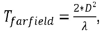
- the aperture of such an antenna array and the wavelength of the signals determine the beginning of the far field of the radiation pattern radiated by the antenna array which is often located far away from the wireless communication device itself, for instance several meters.
- the wireless communication device is typically measured in the near field as each individual antenna element of the antenna array is measured by a near field measuring antenna.
- the far field characteristics of the antenna array, in particular its radiation pattern, cannot be determined due to the fact that only the near field characteristics of the antenna array can be measured.
- tests of the antenna array are performed by conventional over-the-air-measurements (OTA measurements).
- OTA measurements over-the-air-measurements
- the invention provides a wireless communication device comprising a first signal transmitting and/or receiving unit with at least one antenna element for transmitting and/or receiving a communication link signal and a phase reference unit with at least one phase reference member for receiving and/or transmitting a phase reference signal.
- the invention further provides an antenna test device for testing antenna beam characteristics of a wireless communication device, comprising at least one near field measuring antenna for measuring the near field characteristics of a first signal transmitting and/or receiving unit of the wireless communication device and a wireless phase reference interface for receiving and/or transmitting a phase reference signal from and/or to the wireless communication device.
- the invention is based on the finding that a separately formed phase reference unit can be used in order to provide a phase reference used for determining phase relationships appropriately.
- the phase reference is provided in an easy and effective manner such that the measurements can be performed without any greater efforts which reduce the testing time and costs significantly.
- the phase relationship obtained is used for transforming the near field characteristics of the radiation pattern measured by the near field measuring antenna into far field characteristics of the radiation pattern, in particular the one of the first signal transmitting and/or receiving unit.
- beam forming/steering properties of the first signal transmitting and/or receiving unit can be determined.
- the phase reference signal may be a radio frequency, intermediate frequency or clock signal which is used as the reference for the signal(s) processed by the first signal transmitting and/or receiving unit, in particular the different radio waves generating the communication link signal.
- the first transmitting and/or receiving unit comprises an antenna array, in particular wherein the phase reference signal is a reference for all antenna elements of the antenna array.
- the phase reference signal can be used for all antenna elements of the antenna array in order to obtain a phase relationship between the radio waves transmitted and/or received by the individual antenna elements of the antenna array. Due to the phase relationship of the radio waves, the beam steering/forming properties can be determined easily as the phase relationship ensures to determine the far field characteristics of the radiation pattern.
- the resulting phase relationship obtained can be combined with a (conventional) coherent antenna measurement of the individual antenna elements of the antenna array.
- the coherent antenna measurements of the antenna elements can be performed in a phaseless manner. This means that it is not necessary to measure the phase of the radio waves as the separately formed phase reference unit is used for obtaining the phase information. Therefore, the test system can be simplified appropriately.
- the first signal transmitting and/or receiving unit comprises at least one of a transmitter and a receiver.
- the first signal transmitting and/or receiving unit is configured to transmit and/or receive radio waves related to the communication link signal and, further, to process the appropriate radio waves.
- phase reference signal and the communication link signal may be phase locked in a test mode.
- the phase lock of both signals can be selected or switched in the dedicated test mode.
- the phase lock can be activated and deactivated depending on the operation mode of the wireless communication device.
- the phase reference unit is a second signal transmitting and/or receiving unit of a wireless technology different to the one of the first signal transmitting and/or receiving unit. This ensures that no unwanted destructive interferences occur with regard to the communication link signal and the phase reference signal as the different wireless technologies do not interfere with each other.
- the phase reference unit is a light emitting/receiving device, in particular a flash light emitting diode, an infrared light emitting diode and/or a camera sensor. Accordingly, a different type of electromagnetic signal can be used for providing the phase reference signal with regard to the communication link signal, for instance light in the visible frequency range.
- the first signal transmitting and/or receiving unit and phase reference unit use different frequency bands.
- the different frequency bands ensure that unwanted interferences do not occur.
- the frequency bands used may correspond to the frequency bands D and F.
- the communication link signal has a frequency in the range of 3.5 GHz whereas the phase reference signal has a frequency in the range of 1.8 GHz.
- the at least one phase reference member of the phase reference unit is arranged perpendicular to the antenna element of the first signal transmitting and/or receiving unit or on the opposite side with respect to the antenna element of the first signal transmitting and/or receiving unit. This ensures that a maximum distance between the first signal transmitting and/or receiving unit as well as the phase reference unit is provided, in particular its phase reference member, such that unwanted interferences are minimized. Furthermore, the testing setup is simplified appropriately.
- the wireless communication device may be a base station, in particular an Evolved Node B (eNodeB). Accordingly, the wireless communication device may be established by a device that communicates with mobile handsets, also called user equipment such as mobile phones.
- the base station of the eNodeB type ensures inter alia high data rates.
- the phase reference interface is established by a light emitting/receiving device, in particular a flash light emitting diode, an infrared light emitting diode and/or a camera sensor.
- the phase reference interface may directly communicate with the phase reference unit of the wireless communication device that can be established by a light emitting/receiving device such as a flash light emitting diode, an infrared light emitting diode and/or a camera sensor.
- a light emitting/receiving device such as a flash light emitting diode, an infrared light emitting diode and/or a camera sensor.
- the antenna test device and the wireless communication device are enabled to exchange the phase reference signal with each other directly. This means that both devices are configured to receive and to transmit the respective phase reference signal.
- the invention provides a test system comprising at least one of a wireless communication device as described above and an antenna test device as described above.
- the test system is used to test the antenna beam characteristics of the wireless communication device.
- the invention provides a method for testing antenna beam characteristics of a wireless communication device, with the following steps:
- phase relationship of the radio wave used for inter alia generating the communication link signal can be determined while using the separate phase reference signal.
- the measurements to be performed are simplified and the overall measurement time is reduced with respect to the measurement known in the state of the art as the radio wave can be measured in a phaseless manner since the phase relationship is provided by the phase reference signal separately.
- the exchange of the at least one radio wave used for generating the communication link signal may correspond to a (conventional) coherent antenna measurement without any phase measurement of the individual radio wave inter alia generating the communication link signal.
- a phase relationship of the radio wave with respect to the phase reference signal is determined, in particular for the radio waves processed by each antenna element of an antenna array used for exchanging the communication link signal.
- the antenna elements of the antenna array can be measured in a conventional manner without any phase measurement which results in a simplified measurement of the antenna array being less time consuming.
- the antenna test device is configured to receive the separately outputted phase reference signal in order to determine the phase differences of the different radio waves received from the individual antenna elements.
- the antenna test device outputs the phase reference signal that is received by the wireless communication device.
- the phase differences of the radio waves radiated/received by the individual antenna elements can be determined.
- the near field measured may be transformed into a far field.
- the antenna test device is configured to transform the near field characteristics measured by using the near field measuring antenna into a far field in order to determine the beam steering/forming properties of the antenna array.
- a separately formed control and analyzing unit is configured to determine the far field characteristics based upon the near field characteristics determined and the phase reference signal.
- phase reference signal light emitted, light received or a signal using wireless technology different to the one of the communication link signal is used as the phase reference signal.
- a regular wireless communication device can be used for testing purposes wherein the light emitting/receiving unit, for instance a flash LED, is configured to act as the phase reference unit in a certain test mode.
- the light emitting/receiving unit for instance a flash LED
- the test system and the method provides a control and analyzing unit for controlling the wireless communication device and/or the antenna test device. Further, the control and analyzing unit is configured to process the signals received, in particular the radio waves generating the communication link signal as well as the phase reference signal.
- the control and analyzing unit may be formed separately with respect to the wireless communication device and/or the antenna test device.
- the control and analyzing unit is also configured to transform the radiation pattern characteristics appropriately, namely the near field characteristics into far field characteristics in order to determine the beam steering/forming properties of the wireless communication device, namely the antenna beam characteristics.
- a test system 10 for testing antenna beam characteristics of a wireless communication device comprises a wireless communication device 12 and an antenna test device 14.
- the antenna test device 14 has at least one near field measuring antenna element 16 for measuring the near field characteristics of the wireless communication device 12. Further, the antenna test device 14 has a wireless phase reference interface 18 for receiving and/or transmitting a phase reference signal. Generally, the near field measuring antenna element 16 can be used for receiving and/or transmitting radio waves.
- the wireless communication device 12 may be established by a base station, in particular an Evolved Node B, that is used for communicating with mobile end devices such as mobile phones.
- the wireless communication device 12 has a first signal transmitting and/or receiving unit 20 that is established by an antenna array 22 such that the first signal transmitting and/or receiving unit 20 comprises several antenna elements 24.
- the first signal transmitting and/or receiving unit 20 is connected to an internal transceiver 25.
- the wireless communication device 12 may comprise only a transmitter, only a receiver or a transmitter and a receiver separately formed.
- the first signal transmitting and/or receiving unit 20, in particular the several antenna elements 24, is configured to provide a communication link signal that is used to establish a communication channel between the wireless communication device 12 and another wireless communication device, for instance a mobile phone such as a smartphone.
- the wireless communication device 12 comprises a phase reference unit 26 with at least one phase reference member 28 for receiving and/or transmitting a phase reference signal as will be described later.
- the phase reference unit 26 is located at a side of the wireless communication device 12 that is perpendicular to the side of the wireless communication device 12 which comprises the first signal transmitting and/or receiving unit 20. This ensures that the signals of the phase reference unit 26 and the first signal transmitting and/or receiving unit 20 do not interfere with each other which might impair the testing.
- the phase reference unit 26, in particular its phase reference member 28, is provided by a light emitting unit 30, for instance a (flash) light emitting diode (LED) or a infrared light emitting diode.
- a light emitting unit 30 for instance a (flash) light emitting diode (LED) or a infrared light emitting diode.
- the wireless phase reference interface 18 of the antenna test device 14 communicating with the phase reference unit 26 is provided by a light receiving unit 32, for instance a camera sensor (connected to a waveguide such as an optical fiber).
- the testing procedure of the antenna beam characteristics of the radiation pattern comprises the step of exchanging at least one radio wave used for generating a communication link signal between the wireless communication device 12 and the antenna test device 14.
- the antenna array 22 in particular one of its antenna elements 24, may radiate a radio wave used for generating a communication link signal that is received by the near field measuring antenna element 16 of the antenna test device 14.
- the near field measuring antenna element 16 radiates a radio wave received by the antenna array 22, in particular each of the individual antenna elements 24.
- a phase reference signal is exchanged between the wireless communication device 12 and the antenna test device 14.
- the phase reference unit 26 emits a light used as the phase reference signal via its phase reference member 28 that is received by the wireless phase reference interface 18 of the antenna test device 14 such that a phase relationship of the several radio waves received by the antenna array 22 is obtained.
- the antenna test device 14 transmits the phase reference signal that is received by the wireless communication device 12.
- the phase reference signal and the communication link signal are phase locked such that the individual signals received via the antenna array 22, in particular via the individual antenna elements 24, can be put in relation with respect to each other such that the antenna test device 14 is enabled to determine any phase differences.
- This enables the antenna test device 14 to transform the near field characteristics measured into far field characteristics in an appropriate manner.
- control and analyzing unit (not shown in Figure 1 ) can be provided for controlling the wireless communication device 12 and the antenna test device 14 appropriately.
- the antenna array 22 of the wireless communication device 12 is schematically shown illustrating the dependency of the far field generated on the aperture D 2 of the antenna array 22 and the wavelength ⁇ of the signals processed.
- the aperture D 2 mainly corresponds to the (active) area of the antenna array 22 being square in the shown embodiment.
- FIG. 2 another wireless communication device 12 according to the invention is shown that is established by a mobile phone, in particular a smartphone.
- the wireless communication device 12 comprises besides the antenna array 22 establishing the first signal transmitting and/or receiving unit 20, a camera 32 having a camera sensor 34 and a flash light emitting diode 36 representing the light emitting unit 30. Accordingly, the camera 32 relates to a light receiving unit.
- the camera 32 as well as the flash light emitting diode 36 each may be used as the phase reference unit 26.
- the wireless communication device 12 comprises a second antenna array 38 that establishes a second signal transmitting and/or receiving unit 40.
- This second signal transmitting and/or receiving unit 40 can be used as the phase reference unit 26.
- the wireless communication device 12 has another antenna element 42 that can be used as the phase reference unit 26.
- the antenna element 42 may be configured to use a wireless technology being different to the one of the first signal transmitting and/or receiving unit 20 such that disturbing interferences are reduced.
- the communication link signal in particular the different radio waves generating the communication link signal, and the phase reference signal uses different frequency bands.
- the communication link signal uses a frequency band in the range of 3.5 GHz whereas the phase reference signal uses a frequency band in the range of 1.8 GHz.
- the frequency bands D and F may be used.
- the different technologies may relate to Bluetooth, Global System for Mobile Communications (GSM) and/or Long Term Evolution (LTE) or any other suitable wireless technologies.
- the phase reference unit 26 may be located on an opposite side of the wireless communication device 12 such that the interferences are minimized appropriately. This is shown in Figure 2 as the additional antenna elements 42 are on the front side of the wireless communication device 12 (dashed lines) whereas the first signal transmitting and/or receiving unit 20 is located on the respective rear side.
- the test system 10 as well as the method enable the user to determine the far field characteristics of the wireless communication device 12 even though the antenna test device 14 for testing the antenna beam characteristics of the wireless communication device 12 only comprises a near field measuring antenna element 16 that measures the near field characteristics of the radiation pattern appropriately.
- This is enabled as a phase reference is provided even though the individual antenna elements 24 of the first signal transmitting and/or receiving unit 20 used for transmitting/receiving the communication link signal are measured by coherent antenna measurements.
- the additional phase information is retrieved by taking the separate phase reference signal into account.
- phase reference unit 26 used for receiving and/or transmitting a phase reference signal, a phase relationship between the different radio waves of the individual antenna elements 24 of the antenna array 22 used for generating the communication link signal enables the antenna test device 14 to determine the far field characteristics appropriately.
- beam steering/forming properties of the wireless communication device 12 can be determined.
Landscapes
- Physics & Mathematics (AREA)
- Electromagnetism (AREA)
- Engineering & Computer Science (AREA)
- Computer Networks & Wireless Communication (AREA)
- Signal Processing (AREA)
- Radio Transmission System (AREA)
- Mobile Radio Communication Systems (AREA)
- Variable-Direction Aerials And Aerial Arrays (AREA)
Abstract
Description
- The invention relates to a wireless communication device, an antenna test device for testing antenna beam characteristics of a wireless communication device, a test system as well as a method for testing antenna beam characteristics of a wireless communication device.
- Mobile devices such as mobile phones may comprise antenna arrays for exchanging communication link signals with a base station having an antenna array for communication purposes. Accordingly, the base station as well as the mobile devices correspond to wireless communication devices. Generally, the antenna array comprises a set of multiple antenna elements connected to each other. The multiple antennas are interconnected and controlled such that they work together as a single antenna element. The antenna array can be connected to a transmitter and/or a receiver in order to transmit and/or receive electromagnetic signals, in particular radio waves.
- Antenna arrays are typically used for beam steering/forming purposes. Beam steering/forming relates to the changing of the direction of the main lobe of a radiation pattern provided by the antenna (array). This can be achieved by switching the individual antenna elements appropriately and/or by changing the relative phases of the radio waves radiated by the individual antenna elements of the antenna array. The individual radio waves radiated of each individual antenna element can be combined and superposed for beam steering/forming purposes such that they interfere constructively to enhance the power radiated in a direction intended whereas they interfere destructively to reduce the power radiated in directions not intended for signal transmission. For receiving purposes, the individual antenna elements are controlled in a similar manner. Beam steering/forming usually relates to the far field of the radiation pattern provided by the antenna array.
- The aperture of such an antenna array and the wavelength of the signals determine the beginning of the far field of the radiation pattern radiated by the antenna array which is often located far away from the wireless communication device itself, for instance several meters. The transition of the near field to the far field is typically defined by
- At present, tests of the antenna array are performed by conventional over-the-air-measurements (OTA measurements).
- Accordingly, there is a need for a possibility to retrieve information regarding the far field characteristics of the antenna array in an easy and efficient manner in order to determine the beam steering/forming properties.
- The invention provides a wireless communication device comprising a first signal transmitting and/or receiving unit with at least one antenna element for transmitting and/or receiving a communication link signal and a phase reference unit with at least one phase reference member for receiving and/or transmitting a phase reference signal.
- The invention further provides an antenna test device for testing antenna beam characteristics of a wireless communication device, comprising at least one near field measuring antenna for measuring the near field characteristics of a first signal transmitting and/or receiving unit of the wireless communication device and a wireless phase reference interface for receiving and/or transmitting a phase reference signal from and/or to the wireless communication device.
- The invention is based on the finding that a separately formed phase reference unit can be used in order to provide a phase reference used for determining phase relationships appropriately. The phase reference is provided in an easy and effective manner such that the measurements can be performed without any greater efforts which reduce the testing time and costs significantly. The phase relationship obtained is used for transforming the near field characteristics of the radiation pattern measured by the near field measuring antenna into far field characteristics of the radiation pattern, in particular the one of the first signal transmitting and/or receiving unit. Thus, beam forming/steering properties of the first signal transmitting and/or receiving unit can be determined. Generally, the phase reference signal may be a radio frequency, intermediate frequency or clock signal which is used as the reference for the signal(s) processed by the first signal transmitting and/or receiving unit, in particular the different radio waves generating the communication link signal.
- According to an aspect, the first transmitting and/or receiving unit comprises an antenna array, in particular wherein the phase reference signal is a reference for all antenna elements of the antenna array. Accordingly, the phase reference signal can be used for all antenna elements of the antenna array in order to obtain a phase relationship between the radio waves transmitted and/or received by the individual antenna elements of the antenna array. Due to the phase relationship of the radio waves, the beam steering/forming properties can be determined easily as the phase relationship ensures to determine the far field characteristics of the radiation pattern.
- The resulting phase relationship obtained can be combined with a (conventional) coherent antenna measurement of the individual antenna elements of the antenna array. Particularly, the coherent antenna measurements of the antenna elements can be performed in a phaseless manner. This means that it is not necessary to measure the phase of the radio waves as the separately formed phase reference unit is used for obtaining the phase information. Therefore, the test system can be simplified appropriately.
- According to another aspect, the first signal transmitting and/or receiving unit comprises at least one of a transmitter and a receiver. Thus, the first signal transmitting and/or receiving unit is configured to transmit and/or receive radio waves related to the communication link signal and, further, to process the appropriate radio waves.
- Moreover, the phase reference signal and the communication link signal may be phase locked in a test mode. The phase lock of both signals can be selected or switched in the dedicated test mode. Thus, the phase lock can be activated and deactivated depending on the operation mode of the wireless communication device.
- According to an embodiment, the phase reference unit is a second signal transmitting and/or receiving unit of a wireless technology different to the one of the first signal transmitting and/or receiving unit. This ensures that no unwanted destructive interferences occur with regard to the communication link signal and the phase reference signal as the different wireless technologies do not interfere with each other.
- According to another embodiment, the phase reference unit is a light emitting/receiving device, in particular a flash light emitting diode, an infrared light emitting diode and/or a camera sensor. Accordingly, a different type of electromagnetic signal can be used for providing the phase reference signal with regard to the communication link signal, for instance light in the visible frequency range.
- Particularly, the first signal transmitting and/or receiving unit and phase reference unit use different frequency bands. The different frequency bands ensure that unwanted interferences do not occur. The frequency bands used may correspond to the frequency bands D and F. For instance, the communication link signal has a frequency in the range of 3.5 GHz whereas the phase reference signal has a frequency in the range of 1.8 GHz.
- According to another aspect, the at least one phase reference member of the phase reference unit is arranged perpendicular to the antenna element of the first signal transmitting and/or receiving unit or on the opposite side with respect to the antenna element of the first signal transmitting and/or receiving unit. This ensures that a maximum distance between the first signal transmitting and/or receiving unit as well as the phase reference unit is provided, in particular its phase reference member, such that unwanted interferences are minimized. Furthermore, the testing setup is simplified appropriately.
- Moreover, the wireless communication device may be a base station, in particular an Evolved Node B (eNodeB). Accordingly, the wireless communication device may be established by a device that communicates with mobile handsets, also called user equipment such as mobile phones. The base station of the eNodeB type ensures inter alia high data rates.
- According to another aspect, the phase reference interface is established by a light emitting/receiving device, in particular a flash light emitting diode, an infrared light emitting diode and/or a camera sensor. Thus, the phase reference interface may directly communicate with the phase reference unit of the wireless communication device that can be established by a light emitting/receiving device such as a flash light emitting diode, an infrared light emitting diode and/or a camera sensor. Generally, it is ensured that the antenna test device and the wireless communication device are enabled to exchange the phase reference signal with each other directly. This means that both devices are configured to receive and to transmit the respective phase reference signal.
- Further, the invention provides a test system comprising at least one of a wireless communication device as described above and an antenna test device as described above. The test system is used to test the antenna beam characteristics of the wireless communication device. The advantages mentioned above also apply to the test system in a similar manner.
- In addition, the invention provides a method for testing antenna beam characteristics of a wireless communication device, with the following steps:
- Providing a wireless communication device, in particular a wireless communication device as mentioned above,
- Providing an antenna test device, in particular an antenna test device as mentioned above,
- Exchanging at least one radio wave used for generating a communication link signal between the wireless communication device and the antenna test device, and
- Exchanging a phase reference signal between the wireless communication device and the antenna test device.
- Therefore, it is possible that a phase relationship of the radio wave used for inter alia generating the communication link signal can be determined while using the separate phase reference signal. The measurements to be performed are simplified and the overall measurement time is reduced with respect to the measurement known in the state of the art as the radio wave can be measured in a phaseless manner since the phase relationship is provided by the phase reference signal separately.
- The exchange of the at least one radio wave used for generating the communication link signal may correspond to a (conventional) coherent antenna measurement without any phase measurement of the individual radio wave inter alia generating the communication link signal.
- According to an aspect, a phase relationship of the radio wave with respect to the phase reference signal is determined, in particular for the radio waves processed by each antenna element of an antenna array used for exchanging the communication link signal. Thus, the antenna elements of the antenna array can be measured in a conventional manner without any phase measurement which results in a simplified measurement of the antenna array being less time consuming. The antenna test device is configured to receive the separately outputted phase reference signal in order to determine the phase differences of the different radio waves received from the individual antenna elements. Alternatively, the antenna test device outputs the phase reference signal that is received by the wireless communication device.
- As the several phase relationships for each individual antenna element of the antenna array are determined, the phase differences of the radio waves radiated/received by the individual antenna elements can be determined.
- Moreover, the near field measured may be transformed into a far field. Thus, the antenna test device is configured to transform the near field characteristics measured by using the near field measuring antenna into a far field in order to determine the beam steering/forming properties of the antenna array. Alternatively or supplementary, a separately formed control and analyzing unit is configured to determine the far field characteristics based upon the near field characteristics determined and the phase reference signal.
- According to another aspect, light emitted, light received or a signal using wireless technology different to the one of the communication link signal is used as the phase reference signal. Thus, it is ensured that no interferences between the communication link signal and the phase reference signal occur which might impair the testing of the antenna beam characteristics of the wireless communication device.
- Moreover, a regular wireless communication device can be used for testing purposes wherein the light emitting/receiving unit, for instance a flash LED, is configured to act as the phase reference unit in a certain test mode.
- Alternatively or supplementary, the test system and the method provides a control and analyzing unit for controlling the wireless communication device and/or the antenna test device. Further, the control and analyzing unit is configured to process the signals received, in particular the radio waves generating the communication link signal as well as the phase reference signal.
- The control and analyzing unit may be formed separately with respect to the wireless communication device and/or the antenna test device.
- The control and analyzing unit is also configured to transform the radiation pattern characteristics appropriately, namely the near field characteristics into far field characteristics in order to determine the beam steering/forming properties of the wireless communication device, namely the antenna beam characteristics.
- The invention will now be described with reference to the accompanied drawings. In the drawings:
-
Figure 1 shows a test system according to the invention comprising a wireless communication device according to the invention and an antenna test device according to the invention, -
Figure 2 shows a wireless communication device according to another embodiment of the invention, -
Figure 3 shows an antenna array used in the wireless communication device according to the invention, and -
Figure 4 shows a flow chart representing a method for testing antenna beam characteristics of a wireless communication device according to the invention. - In
Figure 1 , atest system 10 for testing antenna beam characteristics of a wireless communication device is shown that comprises awireless communication device 12 and anantenna test device 14. - The
antenna test device 14 has at least one near field measuringantenna element 16 for measuring the near field characteristics of thewireless communication device 12. Further, theantenna test device 14 has a wirelessphase reference interface 18 for receiving and/or transmitting a phase reference signal. Generally, the near field measuringantenna element 16 can be used for receiving and/or transmitting radio waves. - In the shown embodiment, the
wireless communication device 12 may be established by a base station, in particular an Evolved Node B, that is used for communicating with mobile end devices such as mobile phones. - The
wireless communication device 12 has a first signal transmitting and/or receivingunit 20 that is established by anantenna array 22 such that the first signal transmitting and/or receivingunit 20 comprisesseveral antenna elements 24. The first signal transmitting and/or receivingunit 20 is connected to aninternal transceiver 25. Alternatively to thetransceiver 25, thewireless communication device 12 may comprise only a transmitter, only a receiver or a transmitter and a receiver separately formed. - In general, the first signal transmitting and/or receiving
unit 20, in particular theseveral antenna elements 24, is configured to provide a communication link signal that is used to establish a communication channel between thewireless communication device 12 and another wireless communication device, for instance a mobile phone such as a smartphone. - Moreover, the
wireless communication device 12 comprises aphase reference unit 26 with at least onephase reference member 28 for receiving and/or transmitting a phase reference signal as will be described later. - As shown, the
phase reference unit 26 is located at a side of thewireless communication device 12 that is perpendicular to the side of thewireless communication device 12 which comprises the first signal transmitting and/or receivingunit 20. This ensures that the signals of thephase reference unit 26 and the first signal transmitting and/or receivingunit 20 do not interfere with each other which might impair the testing. - In the shown embodiment, the
phase reference unit 26, in particular itsphase reference member 28, is provided by alight emitting unit 30, for instance a (flash) light emitting diode (LED) or a infrared light emitting diode. - Thus, the wireless
phase reference interface 18 of theantenna test device 14 communicating with thephase reference unit 26 is provided by alight receiving unit 32, for instance a camera sensor (connected to a waveguide such as an optical fiber). - As shown in
Figure 4 , the testing procedure of the antenna beam characteristics of the radiation pattern comprises the step of exchanging at least one radio wave used for generating a communication link signal between thewireless communication device 12 and theantenna test device 14. - Thus, the
antenna array 22, in particular one of itsantenna elements 24, may radiate a radio wave used for generating a communication link signal that is received by the near field measuringantenna element 16 of theantenna test device 14. Alternatively, the near field measuringantenna element 16 radiates a radio wave received by theantenna array 22, in particular each of theindividual antenna elements 24. - Simultaneously, a phase reference signal is exchanged between the
wireless communication device 12 and theantenna test device 14. For instance, thephase reference unit 26 emits a light used as the phase reference signal via itsphase reference member 28 that is received by the wirelessphase reference interface 18 of theantenna test device 14 such that a phase relationship of the several radio waves received by theantenna array 22 is obtained. Alternatively, theantenna test device 14 transmits the phase reference signal that is received by thewireless communication device 12. - In a test mode, the phase reference signal and the communication link signal are phase locked such that the individual signals received via the
antenna array 22, in particular via theindividual antenna elements 24, can be put in relation with respect to each other such that theantenna test device 14 is enabled to determine any phase differences. This enables theantenna test device 14 to transform the near field characteristics measured into far field characteristics in an appropriate manner. - Alternatively or supplementary, a separately formed control and analyzing unit (not shown in
Figure 1 ) can be provided for controlling thewireless communication device 12 and theantenna test device 14 appropriately. - In
Figure 3 , theantenna array 22 of thewireless communication device 12 is schematically shown illustrating the dependency of the far field generated on the aperture D2 of theantenna array 22 and the wavelength λ of the signals processed. The aperture D2 mainly corresponds to the (active) area of theantenna array 22 being square in the shown embodiment. - In
Figure 2 , anotherwireless communication device 12 according to the invention is shown that is established by a mobile phone, in particular a smartphone. - The
wireless communication device 12 comprises besides theantenna array 22 establishing the first signal transmitting and/or receivingunit 20, acamera 32 having acamera sensor 34 and a flashlight emitting diode 36 representing thelight emitting unit 30. Accordingly, thecamera 32 relates to a light receiving unit. Thecamera 32 as well as the flashlight emitting diode 36 each may be used as thephase reference unit 26. - Furthermore, the
wireless communication device 12 comprises asecond antenna array 38 that establishes a second signal transmitting and/or receivingunit 40. This second signal transmitting and/or receivingunit 40 can be used as thephase reference unit 26. - Moreover, the
wireless communication device 12 has anotherantenna element 42 that can be used as thephase reference unit 26. Theantenna element 42 may be configured to use a wireless technology being different to the one of the first signal transmitting and/or receivingunit 20 such that disturbing interferences are reduced. - Thus, the communication link signal, in particular the different radio waves generating the communication link signal, and the phase reference signal uses different frequency bands. For instance, the communication link signal uses a frequency band in the range of 3.5 GHz whereas the phase reference signal uses a frequency band in the range of 1.8 GHz. Accordingly, the frequency bands D and F may be used. Further, the different technologies may relate to Bluetooth, Global System for Mobile Communications (GSM) and/or Long Term Evolution (LTE) or any other suitable wireless technologies.
- In order to reduce the interferences, the
phase reference unit 26 may be located on an opposite side of thewireless communication device 12 such that the interferences are minimized appropriately. This is shown inFigure 2 as theadditional antenna elements 42 are on the front side of the wireless communication device 12 (dashed lines) whereas the first signal transmitting and/or receivingunit 20 is located on the respective rear side. - In general, the
test system 10 as well as the method enable the user to determine the far field characteristics of thewireless communication device 12 even though theantenna test device 14 for testing the antenna beam characteristics of thewireless communication device 12 only comprises a near field measuringantenna element 16 that measures the near field characteristics of the radiation pattern appropriately. This is enabled as a phase reference is provided even though theindividual antenna elements 24 of the first signal transmitting and/or receivingunit 20 used for transmitting/receiving the communication link signal are measured by coherent antenna measurements. The additional phase information is retrieved by taking the separate phase reference signal into account. - Due to the additional
phase reference unit 26 used for receiving and/or transmitting a phase reference signal, a phase relationship between the different radio waves of theindividual antenna elements 24 of theantenna array 22 used for generating the communication link signal enables theantenna test device 14 to determine the far field characteristics appropriately. Thus, beam steering/forming properties of thewireless communication device 12 can be determined.
Claims (15)
- A wireless communication device (12) comprising a first signal transmitting and/or receiving unit (20) with at least one antenna element (24) for transmitting and/or receiving a communication link signal and a phase reference unit (26) with at least one phase reference member (28) for receiving and/or transmitting a phase reference signal.
- The wireless communication device (12) according to claim 1, wherein the first signal transmitting and/or receiving unit (20) comprises an antenna array (22), in particular wherein the phase reference signal is a reference for all antenna elements (24) of the antenna array (22).
- The wireless communication device (12) according to claim 1 or 2, wherein the first signal transmitting and/or receiving unit (20) comprises at least one of a transmitter and a receiver.
- The wireless communication device (12) according to any of the preceding claims, wherein the phase reference signal and the communication link signal are phase locked in a test mode.
- The wireless communication device (12) according to any of the preceding claims, wherein the phase reference unit (26) is a second signal transmitting and/or receiving unit (40) of a wireless technology different to the one of the first signal transmitting and/or receiving unit (20).
- The wireless communication device (12) according to any of the claims 1 to 4, wherein the phase reference unit (26) is a light emitting/receiving unit (30), in particular a flash light emitting diode (36), an infrared light emitting diode and/or a camera sensor (34).
- The wireless communication device (12) according to any of the preceding claims, wherein the first signal transmitting and/or receiving unit (20) and phase reference unit (26) use different frequency bands.
- The wireless communication device (12) according to any of the preceding claims, wherein the at least one phase reference member (28) of the phase reference unit (26) is arranged perpendicular to the antenna element (24) of the first signal transmitting and/or receiving unit (20) or on the opposite side with respect to the antenna element (24) of the first signal transmitting and/or receiving unit (20).
- The wireless communication device (12) according to any of the preceding claims, wherein the wireless communication device (12) is a base station, in particular an Evolved Node B.
- An antenna test device (14) for testing antenna beam characteristics of a wireless communication device (12), comprising at least one near field measuring antenna (16) for measuring the near field characteristics of a first signal transmitting and/or receiving unit of the wireless communication device (12) and a wireless phase reference interface (18) for receiving and/or transmitting a phase reference signal from and/or to the wireless communication device (12).
- The antenna test device (14) according to claim 10, wherein the phase reference interface (18) is established by a light emitting/receiving device (32), in particular a flash light emitting diode, an infrared light emitting diode and/or a camera sensor.
- A test system (10), comprising at least one of a wireless communication device (12) according to any of claims 1 to 9 and an antenna test device (14) according to claim 10 or 11.
- A method for testing antenna beam characteristics of a wireless communication device (12), with the following steps:- Providing a wireless communication device (12), in particular a wireless communication device (12) according to any of claims 1 to 9,- Providing an antenna test device (14), in particular an antenna test device (14) according to claim 10 or 11,- Exchanging at least one radio wave used for generating a communication link signal between the wireless communication device (12) and the antenna test device (14), and- Exchanging a phase reference signal between the wireless communication device (12) and the antenna test device (14).
- The method according to claim 13, wherein a phase relationship of the radio wave with respect to the phase reference signal is determined, in particular for the radio waves processed by each antenna element (24) of an antenna array (22) used for exchanging the communication link signal.
- The method according to claim 13 or 14, wherein the near field measured is transformed into a far field.
Priority Applications (1)
| Application Number | Priority Date | Filing Date | Title |
|---|---|---|---|
| EP17182571.4A EP3432491B1 (en) | 2017-07-21 | 2017-07-21 | Wireless communication device, antenna test device, a test system and method for testing antenna beam characteristics |
Applications Claiming Priority (1)
| Application Number | Priority Date | Filing Date | Title |
|---|---|---|---|
| EP17182571.4A EP3432491B1 (en) | 2017-07-21 | 2017-07-21 | Wireless communication device, antenna test device, a test system and method for testing antenna beam characteristics |
Publications (2)
| Publication Number | Publication Date |
|---|---|
| EP3432491A1 true EP3432491A1 (en) | 2019-01-23 |
| EP3432491B1 EP3432491B1 (en) | 2022-01-05 |
Family
ID=59399263
Family Applications (1)
| Application Number | Title | Priority Date | Filing Date |
|---|---|---|---|
| EP17182571.4A Active EP3432491B1 (en) | 2017-07-21 | 2017-07-21 | Wireless communication device, antenna test device, a test system and method for testing antenna beam characteristics |
Country Status (1)
| Country | Link |
|---|---|
| EP (1) | EP3432491B1 (en) |
Cited By (1)
| Publication number | Priority date | Publication date | Assignee | Title |
|---|---|---|---|---|
| EP3945325A1 (en) * | 2020-07-28 | 2022-02-02 | Rohde & Schwarz GmbH & Co. KG | Field probe and method for conducting antenna measurements |
-
2017
- 2017-07-21 EP EP17182571.4A patent/EP3432491B1/en active Active
Non-Patent Citations (3)
| Title |
|---|
| ERICSSON: "On Near-Field testing of AAS BS", vol. TSG RAN, no. Anaheim US; 20151116 - 20151120, 16 November 2015 (2015-11-16), XP051010236, Retrieved from the Internet <URL:http://www.3gpp.org/ftp/Meetings_3GPP_SYNC/RAN4/Docs/> [retrieved on 20151116] * |
| KATHREIN: "Text proposal: Near Field Measurement Method using Standard 3GPP Interfaces", vol. RAN WG4, no. Gothenburg, Sweden; 20160822 - 20160826, 10 August 2016 (2016-08-10), XP051142926, Retrieved from the Internet <URL:http://www.3gpp.org/ftp/tsg_ran/WG4_Radio/TSGR4_80/Docs/> [retrieved on 20160810] * |
| ROHDE AND SCHWARZ: "Antenna Array Testing -Conducted and Over the Air: The Way to 5G White Paper Table of Contents 1MA286_2e Rohde & Schwarz Antenna Array Testing -Conducted and Over the Air: The Way to 5G 2 1 Introduction: What is 5G?", 20 March 2017 (2017-03-20), XP055429495, Retrieved from the Internet <URL:https://cdn.rohde-schwarz.com/pws/dl_downloads/dl_application/application_notes/1ma286/1MA286_2e_AntArrTest_5G.pdf> [retrieved on 20171128] * |
Cited By (2)
| Publication number | Priority date | Publication date | Assignee | Title |
|---|---|---|---|---|
| EP3945325A1 (en) * | 2020-07-28 | 2022-02-02 | Rohde & Schwarz GmbH & Co. KG | Field probe and method for conducting antenna measurements |
| US11835565B2 (en) | 2020-07-28 | 2023-12-05 | Rohde & Schwarz Gmbh & Co. Kg | Field probe and method for conducting antenna measurements |
Also Published As
| Publication number | Publication date |
|---|---|
| EP3432491B1 (en) | 2022-01-05 |
Similar Documents
| Publication | Publication Date | Title |
|---|---|---|
| US11824272B2 (en) | In-field millimeter-wave phased array radiation pattern estimation and validation | |
| US12292522B2 (en) | Determining a position of user equipment by using adaptive phase-changing devices | |
| US12095171B2 (en) | Antenna array calibration systems and methods | |
| CN101916919B (en) | Method of calibrating an active antenna and active antenna | |
| EP3890199B1 (en) | Method and system for testing wireless performance of wireless terminal | |
| KR102079590B1 (en) | A method and apparatus for measuring channel information and feedback in a communication system using beamforming | |
| EP2567478B1 (en) | System and method for simulating electromagnetic environments comprising an array including a plurality of probes | |
| KR101970625B1 (en) | Method and equipment for establishing millimetre connection | |
| CN110402548B (en) | Equipment for configuring reference signal beams based on user equipment positioning accuracy | |
| EP3319242A1 (en) | Device and method for beam forming for estimating direction of terminal | |
| CN107979424B (en) | Test system and method for testing a device under test | |
| US20180146389A1 (en) | Mobile station, base station and radio communication method | |
| US10469183B1 (en) | Antenna device and method for calibrating antenna device | |
| US20200333456A1 (en) | Radar probing employing pilot signals | |
| US9871570B1 (en) | Beam determining unit and beam-searching method for a wireless heterogeneous network | |
| JP6760592B2 (en) | Beacon device, direction estimation method using the beacon device, position estimation method, and communication terminal device | |
| US10110329B2 (en) | System and method for testing with respect to a far-field region | |
| KR20130106236A (en) | Method for analyzing interference between heterogeneous wireless communication system | |
| EP3432491B1 (en) | Wireless communication device, antenna test device, a test system and method for testing antenna beam characteristics | |
| JP2017212673A (en) | Radio communication method and radio communication system | |
| JP2009147687A (en) | Antenna measuring apparatus and method | |
| WO2016180116A1 (en) | Method and device for using beam | |
| US20240421919A1 (en) | Power measurement method and apparatus, and storage medium and program product | |
| US20200213162A1 (en) | Millimeter wave channel estimation method | |
| KR101706204B1 (en) | Method of correcting transceiver of radio channel measurement system with multiple antennas |
Legal Events
| Date | Code | Title | Description |
|---|---|---|---|
| PUAI | Public reference made under article 153(3) epc to a published international application that has entered the european phase |
Free format text: ORIGINAL CODE: 0009012 |
|
| STAA | Information on the status of an ep patent application or granted ep patent |
Free format text: STATUS: THE APPLICATION HAS BEEN PUBLISHED |
|
| AK | Designated contracting states |
Kind code of ref document: A1 Designated state(s): AL AT BE BG CH CY CZ DE DK EE ES FI FR GB GR HR HU IE IS IT LI LT LU LV MC MK MT NL NO PL PT RO RS SE SI SK SM TR |
|
| AX | Request for extension of the european patent |
Extension state: BA ME |
|
| STAA | Information on the status of an ep patent application or granted ep patent |
Free format text: STATUS: REQUEST FOR EXAMINATION WAS MADE |
|
| 17P | Request for examination filed |
Effective date: 20190709 |
|
| RBV | Designated contracting states (corrected) |
Designated state(s): AL AT BE BG CH CY CZ DE DK EE ES FI FR GB GR HR HU IE IS IT LI LT LU LV MC MK MT NL NO PL PT RO RS SE SI SK SM TR |
|
| STAA | Information on the status of an ep patent application or granted ep patent |
Free format text: STATUS: EXAMINATION IS IN PROGRESS |
|
| 17Q | First examination report despatched |
Effective date: 20200214 |
|
| REG | Reference to a national code |
Ref country code: DE Ref legal event code: R079 Ref document number: 602017051786 Country of ref document: DE Free format text: PREVIOUS MAIN CLASS: H04B0017120000 Ipc: H01Q0001240000 |
|
| RIC1 | Information provided on ipc code assigned before grant |
Ipc: H01Q 1/24 20060101AFI20210726BHEP Ipc: H01Q 1/06 20060101ALI20210726BHEP Ipc: H01Q 1/28 20060101ALI20210726BHEP Ipc: H04B 7/06 20060101ALI20210726BHEP Ipc: H04B 17/12 20150101ALI20210726BHEP Ipc: H04B 17/00 20150101ALI20210726BHEP Ipc: G01R 29/10 20060101ALI20210726BHEP Ipc: H01Q 3/26 20060101ALI20210726BHEP Ipc: H01Q 21/06 20060101ALI20210726BHEP Ipc: H01Q 21/28 20060101ALI20210726BHEP |
|
| GRAP | Despatch of communication of intention to grant a patent |
Free format text: ORIGINAL CODE: EPIDOSNIGR1 |
|
| STAA | Information on the status of an ep patent application or granted ep patent |
Free format text: STATUS: GRANT OF PATENT IS INTENDED |
|
| INTG | Intention to grant announced |
Effective date: 20210915 |
|
| GRAS | Grant fee paid |
Free format text: ORIGINAL CODE: EPIDOSNIGR3 |
|
| GRAA | (expected) grant |
Free format text: ORIGINAL CODE: 0009210 |
|
| STAA | Information on the status of an ep patent application or granted ep patent |
Free format text: STATUS: THE PATENT HAS BEEN GRANTED |
|
| RBV | Designated contracting states (corrected) |
Designated state(s): AL AT BE BG CY CZ DE DK EE ES FI FR GB GR HR HU IS IT LT LU LV MC MK MT NL NO PL PT RO RS SE SI SK SM TR |
|
| AK | Designated contracting states |
Kind code of ref document: B1 Designated state(s): AL AT BE BG CY CZ DE DK EE ES FI FR GB GR HR HU IS IT LT LU LV MC MK MT NL NO PL PT RO RS SE SI SK SM TR |
|
| REG | Reference to a national code |
Ref country code: GB Ref legal event code: FG4D |
|
| REG | Reference to a national code |
Ref country code: AT Ref legal event code: REF Ref document number: 1461398 Country of ref document: AT Kind code of ref document: T Effective date: 20220115 |
|
| REG | Reference to a national code |
Ref country code: DE Ref legal event code: R096 Ref document number: 602017051786 Country of ref document: DE |
|
| REG | Reference to a national code |
Ref country code: LT Ref legal event code: MG9D |
|
| REG | Reference to a national code |
Ref country code: NL Ref legal event code: MP Effective date: 20220105 |
|
| REG | Reference to a national code |
Ref country code: AT Ref legal event code: MK05 Ref document number: 1461398 Country of ref document: AT Kind code of ref document: T Effective date: 20220105 |
|
| PG25 | Lapsed in a contracting state [announced via postgrant information from national office to epo] |
Ref country code: NL Free format text: LAPSE BECAUSE OF FAILURE TO SUBMIT A TRANSLATION OF THE DESCRIPTION OR TO PAY THE FEE WITHIN THE PRESCRIBED TIME-LIMIT Effective date: 20220105 |
|
| PG25 | Lapsed in a contracting state [announced via postgrant information from national office to epo] |
Ref country code: SE Free format text: LAPSE BECAUSE OF FAILURE TO SUBMIT A TRANSLATION OF THE DESCRIPTION OR TO PAY THE FEE WITHIN THE PRESCRIBED TIME-LIMIT Effective date: 20220105 Ref country code: RS Free format text: LAPSE BECAUSE OF FAILURE TO SUBMIT A TRANSLATION OF THE DESCRIPTION OR TO PAY THE FEE WITHIN THE PRESCRIBED TIME-LIMIT Effective date: 20220105 Ref country code: PT Free format text: LAPSE BECAUSE OF FAILURE TO SUBMIT A TRANSLATION OF THE DESCRIPTION OR TO PAY THE FEE WITHIN THE PRESCRIBED TIME-LIMIT Effective date: 20220505 Ref country code: NO Free format text: LAPSE BECAUSE OF FAILURE TO SUBMIT A TRANSLATION OF THE DESCRIPTION OR TO PAY THE FEE WITHIN THE PRESCRIBED TIME-LIMIT Effective date: 20220405 Ref country code: LT Free format text: LAPSE BECAUSE OF FAILURE TO SUBMIT A TRANSLATION OF THE DESCRIPTION OR TO PAY THE FEE WITHIN THE PRESCRIBED TIME-LIMIT Effective date: 20220105 Ref country code: HR Free format text: LAPSE BECAUSE OF FAILURE TO SUBMIT A TRANSLATION OF THE DESCRIPTION OR TO PAY THE FEE WITHIN THE PRESCRIBED TIME-LIMIT Effective date: 20220105 Ref country code: ES Free format text: LAPSE BECAUSE OF FAILURE TO SUBMIT A TRANSLATION OF THE DESCRIPTION OR TO PAY THE FEE WITHIN THE PRESCRIBED TIME-LIMIT Effective date: 20220105 Ref country code: BG Free format text: LAPSE BECAUSE OF FAILURE TO SUBMIT A TRANSLATION OF THE DESCRIPTION OR TO PAY THE FEE WITHIN THE PRESCRIBED TIME-LIMIT Effective date: 20220405 |
|
| PG25 | Lapsed in a contracting state [announced via postgrant information from national office to epo] |
Ref country code: PL Free format text: LAPSE BECAUSE OF FAILURE TO SUBMIT A TRANSLATION OF THE DESCRIPTION OR TO PAY THE FEE WITHIN THE PRESCRIBED TIME-LIMIT Effective date: 20220105 Ref country code: LV Free format text: LAPSE BECAUSE OF FAILURE TO SUBMIT A TRANSLATION OF THE DESCRIPTION OR TO PAY THE FEE WITHIN THE PRESCRIBED TIME-LIMIT Effective date: 20220105 Ref country code: GR Free format text: LAPSE BECAUSE OF FAILURE TO SUBMIT A TRANSLATION OF THE DESCRIPTION OR TO PAY THE FEE WITHIN THE PRESCRIBED TIME-LIMIT Effective date: 20220406 Ref country code: FI Free format text: LAPSE BECAUSE OF FAILURE TO SUBMIT A TRANSLATION OF THE DESCRIPTION OR TO PAY THE FEE WITHIN THE PRESCRIBED TIME-LIMIT Effective date: 20220105 Ref country code: AT Free format text: LAPSE BECAUSE OF FAILURE TO SUBMIT A TRANSLATION OF THE DESCRIPTION OR TO PAY THE FEE WITHIN THE PRESCRIBED TIME-LIMIT Effective date: 20220105 |
|
| PG25 | Lapsed in a contracting state [announced via postgrant information from national office to epo] |
Ref country code: IS Free format text: LAPSE BECAUSE OF FAILURE TO SUBMIT A TRANSLATION OF THE DESCRIPTION OR TO PAY THE FEE WITHIN THE PRESCRIBED TIME-LIMIT Effective date: 20220505 |
|
| REG | Reference to a national code |
Ref country code: DE Ref legal event code: R097 Ref document number: 602017051786 Country of ref document: DE |
|
| PG25 | Lapsed in a contracting state [announced via postgrant information from national office to epo] |
Ref country code: SM Free format text: LAPSE BECAUSE OF FAILURE TO SUBMIT A TRANSLATION OF THE DESCRIPTION OR TO PAY THE FEE WITHIN THE PRESCRIBED TIME-LIMIT Effective date: 20220105 Ref country code: SK Free format text: LAPSE BECAUSE OF FAILURE TO SUBMIT A TRANSLATION OF THE DESCRIPTION OR TO PAY THE FEE WITHIN THE PRESCRIBED TIME-LIMIT Effective date: 20220105 Ref country code: RO Free format text: LAPSE BECAUSE OF FAILURE TO SUBMIT A TRANSLATION OF THE DESCRIPTION OR TO PAY THE FEE WITHIN THE PRESCRIBED TIME-LIMIT Effective date: 20220105 Ref country code: EE Free format text: LAPSE BECAUSE OF FAILURE TO SUBMIT A TRANSLATION OF THE DESCRIPTION OR TO PAY THE FEE WITHIN THE PRESCRIBED TIME-LIMIT Effective date: 20220105 Ref country code: DK Free format text: LAPSE BECAUSE OF FAILURE TO SUBMIT A TRANSLATION OF THE DESCRIPTION OR TO PAY THE FEE WITHIN THE PRESCRIBED TIME-LIMIT Effective date: 20220105 Ref country code: CZ Free format text: LAPSE BECAUSE OF FAILURE TO SUBMIT A TRANSLATION OF THE DESCRIPTION OR TO PAY THE FEE WITHIN THE PRESCRIBED TIME-LIMIT Effective date: 20220105 |
|
| PLBE | No opposition filed within time limit |
Free format text: ORIGINAL CODE: 0009261 |
|
| STAA | Information on the status of an ep patent application or granted ep patent |
Free format text: STATUS: NO OPPOSITION FILED WITHIN TIME LIMIT |
|
| PG25 | Lapsed in a contracting state [announced via postgrant information from national office to epo] |
Ref country code: AL Free format text: LAPSE BECAUSE OF FAILURE TO SUBMIT A TRANSLATION OF THE DESCRIPTION OR TO PAY THE FEE WITHIN THE PRESCRIBED TIME-LIMIT Effective date: 20220105 |
|
| 26N | No opposition filed |
Effective date: 20221006 |
|
| PG25 | Lapsed in a contracting state [announced via postgrant information from national office to epo] |
Ref country code: SI Free format text: LAPSE BECAUSE OF FAILURE TO SUBMIT A TRANSLATION OF THE DESCRIPTION OR TO PAY THE FEE WITHIN THE PRESCRIBED TIME-LIMIT Effective date: 20220105 Ref country code: MC Free format text: LAPSE BECAUSE OF FAILURE TO SUBMIT A TRANSLATION OF THE DESCRIPTION OR TO PAY THE FEE WITHIN THE PRESCRIBED TIME-LIMIT Effective date: 20220105 |
|
| REG | Reference to a national code |
Ref country code: BE Ref legal event code: MM Effective date: 20220731 |
|
| PG25 | Lapsed in a contracting state [announced via postgrant information from national office to epo] |
Ref country code: LU Free format text: LAPSE BECAUSE OF NON-PAYMENT OF DUE FEES Effective date: 20220721 |
|
| PG25 | Lapsed in a contracting state [announced via postgrant information from national office to epo] |
Ref country code: BE Free format text: LAPSE BECAUSE OF NON-PAYMENT OF DUE FEES Effective date: 20220731 |
|
| PG25 | Lapsed in a contracting state [announced via postgrant information from national office to epo] |
Ref country code: IT Free format text: LAPSE BECAUSE OF FAILURE TO SUBMIT A TRANSLATION OF THE DESCRIPTION OR TO PAY THE FEE WITHIN THE PRESCRIBED TIME-LIMIT Effective date: 20220105 |
|
| PG25 | Lapsed in a contracting state [announced via postgrant information from national office to epo] |
Ref country code: HU Free format text: LAPSE BECAUSE OF FAILURE TO SUBMIT A TRANSLATION OF THE DESCRIPTION OR TO PAY THE FEE WITHIN THE PRESCRIBED TIME-LIMIT; INVALID AB INITIO Effective date: 20170721 |
|
| PG25 | Lapsed in a contracting state [announced via postgrant information from national office to epo] |
Ref country code: MK Free format text: LAPSE BECAUSE OF FAILURE TO SUBMIT A TRANSLATION OF THE DESCRIPTION OR TO PAY THE FEE WITHIN THE PRESCRIBED TIME-LIMIT Effective date: 20220105 Ref country code: CY Free format text: LAPSE BECAUSE OF FAILURE TO SUBMIT A TRANSLATION OF THE DESCRIPTION OR TO PAY THE FEE WITHIN THE PRESCRIBED TIME-LIMIT Effective date: 20220105 |
|
| PG25 | Lapsed in a contracting state [announced via postgrant information from national office to epo] |
Ref country code: MT Free format text: LAPSE BECAUSE OF FAILURE TO SUBMIT A TRANSLATION OF THE DESCRIPTION OR TO PAY THE FEE WITHIN THE PRESCRIBED TIME-LIMIT Effective date: 20220105 |
|
| P01 | Opt-out of the competence of the unified patent court (upc) registered |
Free format text: CASE NUMBER: UPC_APP_414906/2023 Effective date: 20230525 |
|
| PGFP | Annual fee paid to national office [announced via postgrant information from national office to epo] |
Ref country code: DE Payment date: 20250722 Year of fee payment: 9 |
|
| PGFP | Annual fee paid to national office [announced via postgrant information from national office to epo] |
Ref country code: GB Payment date: 20250724 Year of fee payment: 9 |
|
| PGFP | Annual fee paid to national office [announced via postgrant information from national office to epo] |
Ref country code: FR Payment date: 20250723 Year of fee payment: 9 |
|
| PG25 | Lapsed in a contracting state [announced via postgrant information from national office to epo] |
Ref country code: TR Free format text: LAPSE BECAUSE OF FAILURE TO SUBMIT A TRANSLATION OF THE DESCRIPTION OR TO PAY THE FEE WITHIN THE PRESCRIBED TIME-LIMIT Effective date: 20220105 |