EP3432187A1 - Identity information - Google Patents
Identity information Download PDFInfo
- Publication number
- EP3432187A1 EP3432187A1 EP17305947.8A EP17305947A EP3432187A1 EP 3432187 A1 EP3432187 A1 EP 3432187A1 EP 17305947 A EP17305947 A EP 17305947A EP 3432187 A1 EP3432187 A1 EP 3432187A1
- Authority
- EP
- European Patent Office
- Prior art keywords
- rendering apparatus
- identity information
- user equipment
- rendering
- data
- Prior art date
- Legal status (The legal status is an assumption and is not a legal conclusion. Google has not performed a legal analysis and makes no representation as to the accuracy of the status listed.)
- Granted
Links
Images


Classifications
-
- G—PHYSICS
- G06—COMPUTING OR CALCULATING; COUNTING
- G06F—ELECTRIC DIGITAL DATA PROCESSING
- G06F3/00—Input arrangements for transferring data to be processed into a form capable of being handled by the computer; Output arrangements for transferring data from processing unit to output unit, e.g. interface arrangements
- G06F3/12—Digital output to print unit, e.g. line printer, chain printer
- G06F3/1201—Dedicated interfaces to print systems
- G06F3/1202—Dedicated interfaces to print systems specifically adapted to achieve a particular effect
- G06F3/1203—Improving or facilitating administration, e.g. print management
- G06F3/1204—Improving or facilitating administration, e.g. print management resulting in reduced user or operator actions, e.g. presetting, automatic actions, using hardware token storing data
-
- G—PHYSICS
- G06—COMPUTING OR CALCULATING; COUNTING
- G06F—ELECTRIC DIGITAL DATA PROCESSING
- G06F21/00—Security arrangements for protecting computers, components thereof, programs or data against unauthorised activity
- G06F21/60—Protecting data
- G06F21/606—Protecting data by securing the transmission between two devices or processes
- G06F21/608—Secure printing
-
- G—PHYSICS
- G06—COMPUTING OR CALCULATING; COUNTING
- G06F—ELECTRIC DIGITAL DATA PROCESSING
- G06F3/00—Input arrangements for transferring data to be processed into a form capable of being handled by the computer; Output arrangements for transferring data from processing unit to output unit, e.g. interface arrangements
- G06F3/12—Digital output to print unit, e.g. line printer, chain printer
- G06F3/1201—Dedicated interfaces to print systems
- G06F3/1202—Dedicated interfaces to print systems specifically adapted to achieve a particular effect
- G06F3/1222—Increasing security of the print job
-
- G—PHYSICS
- G06—COMPUTING OR CALCULATING; COUNTING
- G06F—ELECTRIC DIGITAL DATA PROCESSING
- G06F3/00—Input arrangements for transferring data to be processed into a form capable of being handled by the computer; Output arrangements for transferring data from processing unit to output unit, e.g. interface arrangements
- G06F3/12—Digital output to print unit, e.g. line printer, chain printer
- G06F3/1201—Dedicated interfaces to print systems
- G06F3/1223—Dedicated interfaces to print systems specifically adapted to use a particular technique
- G06F3/1224—Client or server resources management
- G06F3/1226—Discovery of devices having required properties
-
- G—PHYSICS
- G06—COMPUTING OR CALCULATING; COUNTING
- G06F—ELECTRIC DIGITAL DATA PROCESSING
- G06F3/00—Input arrangements for transferring data to be processed into a form capable of being handled by the computer; Output arrangements for transferring data from processing unit to output unit, e.g. interface arrangements
- G06F3/12—Digital output to print unit, e.g. line printer, chain printer
- G06F3/1201—Dedicated interfaces to print systems
- G06F3/1223—Dedicated interfaces to print systems specifically adapted to use a particular technique
- G06F3/1237—Print job management
- G06F3/1238—Secure printing, e.g. user identification, user rights for device usage, unallowed content, blanking portions or fields of a page, releasing held jobs
Definitions
- An IT department can manage the identities of rendering apparatus, such as 2D and 3D printers for example, and a pull-print process exists in which a user's print job is held on a server or a user's workstation and released by the user at a printing device, users manually enrol identities of rendering apparatus onto a workstation.
- rendering apparatus such as 2D and 3D printers for example
- a rendering apparatus such as a printer, which may be a 2D or 3D printer for example
- a user can locate information on or near the apparatus that can then be recorded by the user and entered to a user workstation.
- a rendering apparatus can be network addressable from a workstation.
- the apparatus may not be physically suitable for or reachable by the user.
- a user can capture identity information of closely spatially located apparatus. Accordingly, the probability of a user selecting an inappropriate printer is reduced.
- a method for gathering identity certificates of rendering apparatus using a short proximity transport mechanism A physical proximity of the collection process enables rendering apparatus that are nearby the user to be detected.
- a strong cryptographic binding to the apparatus can be delivered to user equipment, such as user's mobile device for example. These certificates can then be provided to the user's workstation from the user equipment to enrol a rendering apparatus and complete the setup process.
- user equipment can be used to to passively capture identities broadcast by rendering apparatus over a short proximity transport mechanism, which can be a low energy radio frequency wireless communication mechanism, peer-to-peer network radio or physical medium (image / sound) for example.
- a short proximity transport mechanism which can be a low energy radio frequency wireless communication mechanism, peer-to-peer network radio or physical medium (image / sound) for example.
- Figure 1 is a schematic representation of a system according to an example.
- user equipment 103 can be a mobile device such as a smart phone, PDA, tablet and so on.
- User equipment 103 can receive data 102 representing identity information broadcast by a rendering apparatus 101 a-c.
- user equipment 103 receives data from three such rendering apparatus, 101a-c, which are located in a region 107.
- the data can be received by the user equipment 103 over a passive non-contact short proximity data transport mechanism when the user equipment 103 is proximate the rendering apparatus.
- User equipment 103 can push the gathered identity information 102 to a workstation 105, to enable the workstation to 105 connect with the rendering apparatus 101a-c.
- the user equipment 103 can passively push the data 102 to the workstation 105 or the workstation 105 can poll or query the user equipment 103 for the data 102.
- the passive non-contact short proximity data transport mechanism can be a low energy radio frequency communication mechanism, such as Bluetooth low energy for example.
- the user equipment 103 can comprise a transceiver 111 to receive data 102 using such a mechanism and transmit data, such as to workstation 105 for example.
- rendering apparatus 101 a-f can broadcast their identity over any low-power broadcast protocol.
- identities can also be displayed on a display of the apparatus, such as an LCD display for example, or can be broadcast via audio.
- transceiver 111 may be replaced by or augmented with an imaging module 120 to capture image data representing the identity information of the rendering apparatus, and/or an acoustic receiver 121 to receive audio data representing the identity information of the rendering apparatus.
- an identity can take the form of a X.509 certificate for use with TLS, or in the form of a public key, a pre-shared key for use with TLS PSK suites, and any suitable metadata.
- the user equipment 103 can passively capture the identity of one or more rendering apparatus 101 a-f and store it internally in a memory 113.
- user equipment 103 is proximate rendering apparatus 101a-c to enable an identity broadcast of these apparatus to be received by user equipment 103 using any of the mechanisms described above.
- Rendering apparatus 101d is in the same region 107 as rendering apparatus 101a-c, but may be located behind a door for example. Therefore, although it may appear (e.g. based on network addressability of apparatus 101d) to be a suitable candidate for use with workstation 105, it may in fact be inaccessible to the user and so any print job sent to the apparatus may be difficult to retrieve.
- the user equipment 103 Since the user equipment 103 is unable to come within range of a broadcast of apparatus 101d given its location behind a door for example, the user equipment does not receive identity information for this apparatus. The same is true for rendering apparatus 101e and 101f in region 109. They may appear (e.g. based on network addressability) to be suitable, but the region 109 may be inaccessible to a user.
- the user equipment can passively transport all captured identities and enroll them at the workstation 105.
- captured identity data can be transmitted 125 to workstation 105 using a wireless data transport mechanism such as wifi or Bluetooth and so on.
- user equipment 103 may communicate a captured identity to workstation 105 over a wired link between the user equipment and the workstation.
- multiple rendering apparatus can act as a mesh network, and periodically poll nearby apparatus for new identities.
- rendering apparatus can aggregate sets of identities, and a user can therefore encounter an increases probability that they will capture a suitable identity.
- Figure 2 is a schematic representation of a mesh network according to an example.
- User equipment 202 in region 220 receives an identity 204 from rendering apparatus 201.
- Other apparatus shown in figure 2 are not within range of user equipment 202.
- apparatus 201 can poll apparatus 203 for its identity along with the identity of any other rendering apparatus that it (203) is in contact with, which in the example, of figure 2 is apparatus 205.
- Apparatus 205 is in contact with apparatus 207, 211 and 213, and apparatus 207 is in contact with apparatus 209.
- a mesh network is formed in which apparatus 203 may ultimately pass the identities of itself and apparatus 205, 207, 209, 211 and 213 to apparatus 201.
- user equipment 202 receives the data 204 it may comprise the identities of the other apparatus in the network 200.
- any captured cryptographic material received as part of an identity can be used in a secure printing protocol. For example, to encrypt a print job under a printer's key.
- FIG 3 is a schematic representation of a rendering apparatus according to an example.
- Rendering apparatus 301 can be a printer, such as a 2D or 3D printer for example.
- the apparatus 301 comprises a processor 303.
- the processor 303 is configured to execute instructions 305 to generate or receive data representing identity information of the rendering apparatus.
- the apparatus can be configured to receive an identity at time of deployment which can be subsequently modified or updated, such as if the apparatus is moved within an environment for example.
- the processor 303 can execute instructions 305 to generate identity information for the apparatus 301.
- the identity information can be broadcast by the apparatus 301 using a passive non-contact short proximity data transport mechanism of the rendering apparatus.
- apparatus 301 comprises a transceiver 307 to enable the apparatus 301 to broadcast its identity over a low-power broadcast protocol.
- the apparatus can display an identity on a display 309 of the apparatus, such as an LCD display for example, or can broadcast an identity via audio using a speaker 311 for example.
- transceiver 307 may be replaced by or augmented with a display 309 and/or an acoustic transmitter 311.
- identity information 313, which may be generated or received by apparatus 301 can be a certificate, public cryptographic or shared key, metadata, visual or acoustic data.
- apparatus 301 comprises a memory 315 to store data representing a set of aggregate identities of multiple other rendering apparatus along with the identity 313 for example.
- identify data of multiple other rendering apparatus can be stored in memory 307 and can be broadcast by apparatus 301. The apparatus 301 can therefore poll multiple other rendering apparatus for their respective identity information to generate a set of aggregate identities 317.
- FIG. 4 is a flow chart of a method according to an example.
- data is received at a mobile user apparatus (user equipment) that is temporarily proximate a rendering apparatus.
- a user equipment can pass a rendering apparatus as a user holding the equipment walks past it.
- the apparatus may be continuously or intermittently broadcast its identity information to enable devices to easily enrol the apparatus at a workstation. That is, the apparatus can broadcast data representing identity information of the rendering apparatus using a passive non-contact short proximity data transport mechanism as described above.
- the user equipment can passively transmit the identity information to an apparatus (such as a workstation for example), to enable the apparatus to connect with the rendering apparatus.
- user equipment can receive data broadcast from the rendering apparatus that provides identity information of the rendering apparatus.
- the data may also include identity information of one or more other rendering apparatus as described above with reference to figure 2 for example.
- the user equipment can store the data.
- the user equipment When the user equipment is within communication range of a workstation, for example, or linked to the workstation using a cable or dock and so on, it can push the data representing the identity information of the one or more rendering apparatus to the workstation in order to enable the rendering apparatus to be enrolled at the workstation.
- a user can gain access to one or more rendering apparatus without having to manually enrol them. Furthermore, usability of rendering apparatus is increased since the probability of a user finding a suitable apparatus without having to do any explicit discovery work themselves is increased. In an example therefore, a user, potentially, does not have to perform any interactions at all.
- the identity information can be transmitted from user equipment to a workstation over a second data transport mechanism.
- the second data transport mechanism can be the same as or different to the mechanism used to receive the identity information from a rendering apparatus.
- FIG. 5 is a flow chart of a method according to an example.
- an identity received at a user equipment as a certificate, public cryptographic or shared key, metadata, visual or acoustic data (block 501) is enrolled (503) at an apparatus such as a workstation for example.
- the identity can be pushed to the workstation using a wireless or wired link.
- the workstation may poll user equipment for any new identity information data.
- Examples in the present disclosure can be provided as methods, systems or machine-readable instructions, such as any combination of software, hardware, firmware or the like.
- Such machine-readable instructions may be included on a computer readable storage medium (including but not limited to disc storage, CD-ROM, optical storage, etc.) having computer readable program codes therein or thereon.
- the machine-readable instructions may, for example, be executed by a general-purpose computer, a special purpose computer, an embedded processor or processors of other programmable data processing devices to realize the functions described in the description and diagrams.
- a processor or processing apparatus may execute the machine-readable instructions.
- modules of a user equipment or rendering apparatus may be implemented by a processor executing machine readable instructions stored in a memory, or a processor operating in accordance with instructions embedded in logic circuitry.
- the term 'processor' is to be interpreted broadly to include a CPU, processing unit, ASIC, logic unit, or programmable gate set etc.
- the methods and modules may all be performed by a single processor or divided amongst several processors.
- Such machine-readable instructions may also be stored in a computer readable storage that can guide the computer or other programmable data processing devices to operate in a specific mode.
- the instructions may be provided on a non-transitory computer readable storage medium encoded with instructions, executable by a processor.
- Figure 6 shows an example of an apparatus 600 comprising a processor 650 associated with a memory 652.
- the apparatus may be user equipment or a rendering apparatus, as described above.
- the memory 652 comprises computer readable instructions 654 which are executable by the processor 650.
- the instructions 654 can comprise one or more of:
- Such machine-readable instructions may also be loaded onto a computer or other programmable data processing devices, so that the computer or other programmable data processing devices perform a series of operations to produce computer-implemented processing, thus the instructions executed on the computer or other programmable devices provide an operation for realizing functions specified by flow(s) in the flow charts and/or block(s) in the block diagrams.
- teachings herein may be implemented in the form of a computer software product, the computer software product being stored in a storage medium and comprising a plurality of instructions for making a computer device implement the methods recited in the examples of the present disclosure.
Landscapes
- Engineering & Computer Science (AREA)
- Theoretical Computer Science (AREA)
- Physics & Mathematics (AREA)
- General Engineering & Computer Science (AREA)
- General Physics & Mathematics (AREA)
- Human Computer Interaction (AREA)
- Computer Security & Cryptography (AREA)
- Health & Medical Sciences (AREA)
- Bioethics (AREA)
- General Health & Medical Sciences (AREA)
- Computer Hardware Design (AREA)
- Software Systems (AREA)
- Mobile Radio Communication Systems (AREA)
Abstract
Description
- An IT department can manage the identities of rendering apparatus, such as 2D and 3D printers for example, and a pull-print process exists in which a user's print job is held on a server or a user's workstation and released by the user at a printing device, users manually enrol identities of rendering apparatus onto a workstation.
- Various features of certain examples will be apparent from the detailed description which follows, taken in conjunction with the accompanying drawings, which together illustrate, by way of example only, a number of features, and wherein:
-
Figure 1 is a schematic representation of a system according to an example; -
Figure 2 is a schematic representation of a mesh network according to an example; -
Figure 3 is a schematic representation of a rendering apparatus according to an example; -
Figure 4 is a flow chart of a method according to an example; -
Figure 5 is a flow chart of a method according to an example; and -
Figure 6 is a schematic representation of an apparatus comprising a processor associated with a memory according to an example. - In the following description, for purposes of explanation, numerous specific details of certain examples are set forth. Reference in the specification to "an example" or similar language means that a particular feature, structure, or characteristic described in connection with the example is included in at least that one example, but not necessarily in other examples.
- To manually enrol an identity of a rendering apparatus, such as a printer, which may be a 2D or 3D printer for example, a user can locate information on or near the apparatus that can then be recorded by the user and entered to a user workstation.
- In some cases, a rendering apparatus can be network addressable from a workstation. However, the apparatus may not be physically suitable for or reachable by the user. In an example, a user can capture identity information of closely spatially located apparatus. Accordingly, the probability of a user selecting an inappropriate printer is reduced.
- According to an example, there is provided a method for gathering identity certificates of rendering apparatus using a short proximity transport mechanism. A physical proximity of the collection process enables rendering apparatus that are nearby the user to be detected. In an example, a strong cryptographic binding to the apparatus can be delivered to user equipment, such as user's mobile device for example. These certificates can then be provided to the user's workstation from the user equipment to enrol a rendering apparatus and complete the setup process.
- Accordingly, user equipment can be used to to passively capture identities broadcast by rendering apparatus over a short proximity transport mechanism, which can be a low energy radio frequency wireless communication mechanism, peer-to-peer network radio or physical medium (image / sound) for example.
-
Figure 1 is a schematic representation of a system according to an example. In an example,user equipment 103 can be a mobile device such as a smart phone, PDA, tablet and so on.User equipment 103 can receivedata 102 representing identity information broadcast by a rendering apparatus 101 a-c. In the example offigure 1 ,user equipment 103 receives data from three such rendering apparatus, 101a-c, which are located in aregion 107. The data can be received by theuser equipment 103 over a passive non-contact short proximity data transport mechanism when theuser equipment 103 is proximate the rendering apparatus. -
User equipment 103 can push the gatheredidentity information 102 to aworkstation 105, to enable the workstation to 105 connect with therendering apparatus 101a-c. In an example, theuser equipment 103 can passively push thedata 102 to theworkstation 105 or theworkstation 105 can poll or query theuser equipment 103 for thedata 102. - According to an example, the passive non-contact short proximity data transport mechanism can be a low energy radio frequency communication mechanism, such as Bluetooth low energy for example. The
user equipment 103 can comprise atransceiver 111 to receivedata 102 using such a mechanism and transmit data, such as toworkstation 105 for example. - In an example, rendering apparatus 101 a-f can broadcast their identity over any low-power broadcast protocol. However, such identities can also be displayed on a display of the apparatus, such as an LCD display for example, or can be broadcast via audio. Accordingly,
transceiver 111 may be replaced by or augmented with animaging module 120 to capture image data representing the identity information of the rendering apparatus, and/or anacoustic receiver 121 to receive audio data representing the identity information of the rendering apparatus. - In an example, an identity can take the form of a X.509 certificate for use with TLS, or in the form of a public key, a pre-shared key for use with TLS PSK suites, and any suitable metadata.
- According to an example, as a user walks around a location, such as n office in their normal course of work for example, the
user equipment 103 can passively capture the identity of one or more rendering apparatus 101 a-f and store it internally in amemory 113. In the example offigure 1 for example,user equipment 103 isproximate rendering apparatus 101a-c to enable an identity broadcast of these apparatus to be received byuser equipment 103 using any of the mechanisms described above. Renderingapparatus 101d is in thesame region 107 as renderingapparatus 101a-c, but may be located behind a door for example. Therefore, although it may appear (e.g. based on network addressability ofapparatus 101d) to be a suitable candidate for use withworkstation 105, it may in fact be inaccessible to the user and so any print job sent to the apparatus may be difficult to retrieve. - Since the
user equipment 103 is unable to come within range of a broadcast ofapparatus 101d given its location behind a door for example, the user equipment does not receive identity information for this apparatus. The same is true for renderingapparatus region 109. They may appear (e.g. based on network addressability) to be suitable, but theregion 109 may be inaccessible to a user. - When the user returns to their desk for example, the user equipment can passively transport all captured identities and enroll them at the
workstation 105. For example, usingtransceiver 111, captured identity data can be transmitted 125 toworkstation 105 using a wireless data transport mechanism such as wifi or Bluetooth and so on. Alternatively,user equipment 103 may communicate a captured identity toworkstation 105 over a wired link between the user equipment and the workstation. - According to an example, multiple rendering apparatus can act as a mesh network, and periodically poll nearby apparatus for new identities. In this manner, rendering apparatus can aggregate sets of identities, and a user can therefore encounter an increases probability that they will capture a suitable identity.
-
Figure 2 is a schematic representation of a mesh network according to an example.User equipment 202 inregion 220 receives anidentity 204 from renderingapparatus 201. Other apparatus shown infigure 2 are not within range ofuser equipment 202. However,apparatus 201 can pollapparatus 203 for its identity along with the identity of any other rendering apparatus that it (203) is in contact with, which in the example, offigure 2 isapparatus 205.Apparatus 205 is in contact withapparatus apparatus 207 is in contact withapparatus 209. Accordingly, a mesh network is formed in whichapparatus 203 may ultimately pass the identities of itself andapparatus apparatus 201. Whenuser equipment 202 receives thedata 204 it may comprise the identities of the other apparatus in thenetwork 200. - In an example, any captured cryptographic material received as part of an identity can be used in a secure printing protocol. For example, to encrypt a print job under a printer's key.
-
Figure 3 is a schematic representation of a rendering apparatus according to an example. Renderingapparatus 301 can be a printer, such as a 2D or 3D printer for example. In an example, theapparatus 301 comprises aprocessor 303. Theprocessor 303 is configured to executeinstructions 305 to generate or receive data representing identity information of the rendering apparatus. For example, the apparatus can be configured to receive an identity at time of deployment which can be subsequently modified or updated, such as if the apparatus is moved within an environment for example. Theprocessor 303 can executeinstructions 305 to generate identity information for theapparatus 301. In either case, the identity information can be broadcast by theapparatus 301 using a passive non-contact short proximity data transport mechanism of the rendering apparatus. - In an example,
apparatus 301 comprises atransceiver 307 to enable theapparatus 301 to broadcast its identity over a low-power broadcast protocol. In addition, or in place of the use oftransceiver 307 to broadcast an identity, the apparatus can display an identity on adisplay 309 of the apparatus, such as an LCD display for example, or can broadcast an identity via audio using aspeaker 311 for example. Accordingly,transceiver 307 may be replaced by or augmented with adisplay 309 and/or anacoustic transmitter 311. - According to an example,
identity information 313, which may be generated or received byapparatus 301, can be a certificate, public cryptographic or shared key, metadata, visual or acoustic data. In an example,apparatus 301 comprises amemory 315 to store data representing a set of aggregate identities of multiple other rendering apparatus along with theidentity 313 for example. With reference tofigure 2 , identify data of multiple other rendering apparatus can be stored inmemory 307 and can be broadcast byapparatus 301. Theapparatus 301 can therefore poll multiple other rendering apparatus for their respective identity information to generate a set ofaggregate identities 317. -
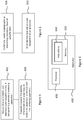
Figure 4 is a flow chart of a method according to an example. Inblock 401 data is received at a mobile user apparatus (user equipment) that is temporarily proximate a rendering apparatus. For example, a user equipment can pass a rendering apparatus as a user holding the equipment walks past it. The apparatus may be continuously or intermittently broadcast its identity information to enable devices to easily enrol the apparatus at a workstation. That is, the apparatus can broadcast data representing identity information of the rendering apparatus using a passive non-contact short proximity data transport mechanism as described above. Inblock 403, the user equipment can passively transmit the identity information to an apparatus (such as a workstation for example), to enable the apparatus to connect with the rendering apparatus. - Accordingly, as user equipment passes a rendering apparatus, it can receive data broadcast from the rendering apparatus that provides identity information of the rendering apparatus. The data may also include identity information of one or more other rendering apparatus as described above with reference to
figure 2 for example. The user equipment can store the data. When the user equipment is within communication range of a workstation, for example, or linked to the workstation using a cable or dock and so on, it can push the data representing the identity information of the one or more rendering apparatus to the workstation in order to enable the rendering apparatus to be enrolled at the workstation. - Therefore, a user can gain access to one or more rendering apparatus without having to manually enrol them. Furthermore, usability of rendering apparatus is increased since the probability of a user finding a suitable apparatus without having to do any explicit discovery work themselves is increased. In an example therefore, a user, potentially, does not have to perform any interactions at all.
- In an example, the identity information can be transmitted from user equipment to a workstation over a second data transport mechanism. The second data transport mechanism can be the same as or different to the mechanism used to receive the identity information from a rendering apparatus.
-
Figure 5 is a flow chart of a method according to an example. Inblock 503, an identity received at a user equipment as a certificate, public cryptographic or shared key, metadata, visual or acoustic data (block 501) is enrolled (503) at an apparatus such as a workstation for example. As noted above, the identity can be pushed to the workstation using a wireless or wired link. In an example, the workstation may poll user equipment for any new identity information data. - Examples in the present disclosure can be provided as methods, systems or machine-readable instructions, such as any combination of software, hardware, firmware or the like. Such machine-readable instructions may be included on a computer readable storage medium (including but not limited to disc storage, CD-ROM, optical storage, etc.) having computer readable program codes therein or thereon.
- The present disclosure is described with reference to flow charts and/or block diagrams of the method, devices and systems according to examples of the present disclosure. Although the flow diagrams described above show a specific order of execution, the order of execution may differ from that which is depicted. Blocks described in relation to one flow chart may be combined with those of another flow chart. In some examples, some blocks of the flow diagrams may not be necessary and/or additional blocks may be added. It shall be understood that each flow and/or block in the flow charts and/or block diagrams, as well as combinations of the flows and/or diagrams in the flow charts and/or block diagrams can be realized by machine readable instructions.
- The machine-readable instructions may, for example, be executed by a general-purpose computer, a special purpose computer, an embedded processor or processors of other programmable data processing devices to realize the functions described in the description and diagrams. In particular, a processor or processing apparatus may execute the machine-readable instructions. Thus, modules of a user equipment or rendering apparatus may be implemented by a processor executing machine readable instructions stored in a memory, or a processor operating in accordance with instructions embedded in logic circuitry. The term 'processor' is to be interpreted broadly to include a CPU, processing unit, ASIC, logic unit, or programmable gate set etc. The methods and modules may all be performed by a single processor or divided amongst several processors.
- Such machine-readable instructions may also be stored in a computer readable storage that can guide the computer or other programmable data processing devices to operate in a specific mode.
- For example, the instructions may be provided on a non-transitory computer readable storage medium encoded with instructions, executable by a processor.
-
Figure 6 shows an example of anapparatus 600 comprising aprocessor 650 associated with amemory 652. The apparatus may be user equipment or a rendering apparatus, as described above. Thememory 652 comprises computerreadable instructions 654 which are executable by theprocessor 650. Theinstructions 654 can comprise one or more of: - Instructions to receive data, at a mobile user apparatus temporarily proximate the rendering apparatus, representing identity information broadcast by the rendering apparatus over a passive non-contact short proximity data transport mechanism;
- Instruction to passively transmit the identity information to an apparatus, to enable the apparatus to connect with the rendering apparatus;
- Instructions to transmit identity information from a rendering apparatus, periodically or continuously; and
- Instructions to poll a rendering apparatus for identity information.
- Such machine-readable instructions may also be loaded onto a computer or other programmable data processing devices, so that the computer or other programmable data processing devices perform a series of operations to produce computer-implemented processing, thus the instructions executed on the computer or other programmable devices provide an operation for realizing functions specified by flow(s) in the flow charts and/or block(s) in the block diagrams.
- Further, the teachings herein may be implemented in the form of a computer software product, the computer software product being stored in a storage medium and comprising a plurality of instructions for making a computer device implement the methods recited in the examples of the present disclosure.
- While the method, apparatus and related aspects have been described with reference to certain examples, various modifications, changes, omissions, and substitutions can be made without departing from the spirit of the present disclosure. In particular, a feature or block from one example may be combined with or substituted by a feature/block of another example.
- The word "comprising" does not exclude the presence of elements other than those listed in a claim, "a" or "an" does not exclude a plurality, and a single processor or other unit may fulfil the functions of several units recited in the claims.
- The features of any dependent claim may be combined with the features of any of the independent claims or other dependent claims.
Claims (15)
- User equipment, the user equipment to:receive data representing identity information broadcast by a rendering apparatus over a passive non-contact short proximity data transport mechanism when the user equipment is proximate the rendering apparatus; andpush the gathered identity information to a workstation, to enable the workstation to connect with the rendering apparatus.
- User equipment as claimed in claim 1, further comprising a memory to store data representing multiple rendering apparatus.
- User equipment as claimed in claim 1, further comprising an imaging module to capture image data representing the identity information of the rendering apparatus.
- User equipment as claimed in claim 1, further comprising an acoustic receiver to receive audio data representing the identity information of the rendering apparatus.
- A method for determining the identity of a rendering apparatus, the method comprising:receiving data, at a mobile user apparatus temporarily proximate the rendering apparatus, representing identity information broadcast by the rendering apparatus over a passive non-contact short proximity data transport mechanism; andpassively transmitting the identity information to an apparatus, to enable the apparatus to connect with the rendering apparatus.
- A method as claimed in claim 5, wherein the identity information is in the form of a certificate, public cryptographic or shared key, metadata, visual or acoustic data.
- A method as claimed in claim 5, further comprising enrolling the identity information at the apparatus.
- A method as claimed in claim 5, wherein transmitting the identity information comprises transmitting over a second data transport mechanism.
- A method as claimed in claim 5, further comprising:receiving identity information at the rendering apparatus from multiple other rendering apparatus.
- A method as claimed in claim 10, further comprising;
polling the multiple other rendering apparatus for their respective identity information. - A method as claimed in claim 9, further comprising aggregating the identity information from the multiple other rendering apparatus to generate a set of identities.
- A rendering apparatus comprising a processor to execute instructions to:generate or receive data representing identity information of the rendering apparatus; andbroadcast the data using a passive non-contact short proximity data transport mechanism of the rendering apparatus.
- A rendering apparatus as claimed in claim 12, wherein the identity information is a certificate, public cryptographic or shared key, metadata, visual or acoustic data.
- A rendering apparatus as claimed in claim 12, further comprising a memory to store data representing a set of aggregate identities of multiple other rendering apparatus.
- A rendering apparatus as claimed in claim 14, the rendering apparatus to poll the multiple other rendering apparatus for their respective identity information to generate the set of aggregate identities.
Priority Applications (3)
| Application Number | Priority Date | Filing Date | Title |
|---|---|---|---|
| EP17305947.8A EP3432187B1 (en) | 2017-07-17 | 2017-07-17 | Identity information |
| US16/628,755 US11137948B2 (en) | 2017-07-17 | 2018-07-13 | User equipment to capture identity information from rendering apparatuses |
| PCT/US2018/041941 WO2019018216A1 (en) | 2017-07-17 | 2018-07-13 | Identity information |
Applications Claiming Priority (1)
| Application Number | Priority Date | Filing Date | Title |
|---|---|---|---|
| EP17305947.8A EP3432187B1 (en) | 2017-07-17 | 2017-07-17 | Identity information |
Publications (2)
| Publication Number | Publication Date |
|---|---|
| EP3432187A1 true EP3432187A1 (en) | 2019-01-23 |
| EP3432187B1 EP3432187B1 (en) | 2020-10-21 |
Family
ID=59388032
Family Applications (1)
| Application Number | Title | Priority Date | Filing Date |
|---|---|---|---|
| EP17305947.8A Not-in-force EP3432187B1 (en) | 2017-07-17 | 2017-07-17 | Identity information |
Country Status (3)
| Country | Link |
|---|---|
| US (1) | US11137948B2 (en) |
| EP (1) | EP3432187B1 (en) |
| WO (1) | WO2019018216A1 (en) |
Citations (4)
| Publication number | Priority date | Publication date | Assignee | Title |
|---|---|---|---|---|
| US20130027741A1 (en) * | 2011-07-29 | 2013-01-31 | Eric Liu | Printer registration |
| US20130141755A1 (en) * | 2011-12-02 | 2013-06-06 | Apple Inc. | Facilitating communication between portable electronic devices and printers |
| US20140093079A1 (en) * | 2012-09-29 | 2014-04-03 | Microsoft Corporation | Securely joining a secure wireless communications network |
| EP2928172A2 (en) * | 2014-04-02 | 2015-10-07 | Samsung Electronics Co., Ltd. | Image forming aparatus supporting function of near field communication and method of setting nfc operation mode thereof |
Family Cites Families (16)
| Publication number | Priority date | Publication date | Assignee | Title |
|---|---|---|---|---|
| ES2318611T3 (en) | 2001-06-18 | 2009-05-01 | Research In Motion Limited | SYSTEM AND METHOD FOR MANAGING ATTACHED MESSAGE ELEMENTS. |
| TWI276325B (en) | 2005-09-16 | 2007-03-11 | Hon Hai Prec Ind Co Ltd | Mobile communication device and method for downloading configuration files thereof and wireless communication system |
| KR101415033B1 (en) | 2007-07-06 | 2014-07-07 | 삼성전자주식회사 | Print control method using mobile communication device, print control system and mobile communication device |
| JP5473471B2 (en) * | 2009-08-11 | 2014-04-16 | キヤノン株式会社 | COMMUNICATION SYSTEM, COMMUNICATION DEVICE, AND ITS CONTROL METHOD |
| EP2817708B1 (en) | 2012-02-21 | 2020-08-26 | Zebra Technologies Corporation | Method and apparatus for implementing near field communications with a printer |
| CN103257835A (en) | 2013-04-12 | 2013-08-21 | 博韩伟业(北京)科技有限公司 | Printing system with Bluetooth function and working method of printing system with Bluetooth function |
| JP6546372B2 (en) * | 2014-01-27 | 2019-07-17 | ブラザー工業株式会社 | Wireless communication device |
| KR20150138797A (en) * | 2014-06-02 | 2015-12-10 | 삼성전자주식회사 | Image forming apparatus and method for controllng of printing |
| KR20160001530A (en) * | 2014-06-27 | 2016-01-06 | 삼성전자주식회사 | Image forming apparatus and image forming method |
| KR101868444B1 (en) * | 2014-07-01 | 2018-07-23 | 에이치피프린팅코리아 주식회사 | Image forming apparatus, position guiding method thereof and image forming system |
| JP2016062232A (en) * | 2014-09-17 | 2016-04-25 | 株式会社リコー | Information processing system, information processing apparatus, program, and information processing method |
| US9367271B2 (en) | 2014-10-28 | 2016-06-14 | Xerox Corporation | System and method for achieving tap-to-print functionality on a mobile device |
| JP6589314B2 (en) * | 2015-03-19 | 2019-10-16 | 富士ゼロックス株式会社 | Image forming system, image processing apparatus, image forming method, and program |
| JP6314920B2 (en) * | 2015-06-25 | 2018-04-25 | 京セラドキュメントソリューションズ株式会社 | Image forming apparatus |
| CN106878917B (en) | 2015-12-11 | 2021-07-09 | 比亚迪股份有限公司 | Information transmission control method, system, terminal and data collector |
| JP2018207246A (en) * | 2017-06-01 | 2018-12-27 | コニカミノルタ株式会社 | Information processing apparatus, data transmission method, and computer program |
-
2017
- 2017-07-17 EP EP17305947.8A patent/EP3432187B1/en not_active Not-in-force
-
2018
- 2018-07-13 US US16/628,755 patent/US11137948B2/en not_active Expired - Fee Related
- 2018-07-13 WO PCT/US2018/041941 patent/WO2019018216A1/en not_active Ceased
Patent Citations (4)
| Publication number | Priority date | Publication date | Assignee | Title |
|---|---|---|---|---|
| US20130027741A1 (en) * | 2011-07-29 | 2013-01-31 | Eric Liu | Printer registration |
| US20130141755A1 (en) * | 2011-12-02 | 2013-06-06 | Apple Inc. | Facilitating communication between portable electronic devices and printers |
| US20140093079A1 (en) * | 2012-09-29 | 2014-04-03 | Microsoft Corporation | Securely joining a secure wireless communications network |
| EP2928172A2 (en) * | 2014-04-02 | 2015-10-07 | Samsung Electronics Co., Ltd. | Image forming aparatus supporting function of near field communication and method of setting nfc operation mode thereof |
Non-Patent Citations (1)
| Title |
|---|
| JORDAN PUSEY: "Setting Up Proximity Printing with Citrix", 30 March 2016 (2016-03-30), XP055403669, Retrieved from the Internet <URL:https://www.printerlogic.com/blog/setting-proximity-printing-citrix/> [retrieved on 20170904] * |
Also Published As
| Publication number | Publication date |
|---|---|
| EP3432187B1 (en) | 2020-10-21 |
| US20200293234A1 (en) | 2020-09-17 |
| WO2019018216A1 (en) | 2019-01-24 |
| US11137948B2 (en) | 2021-10-05 |
Similar Documents
| Publication | Publication Date | Title |
|---|---|---|
| US11259178B2 (en) | Bluetooth mesh network provisioning authentication | |
| JP6759011B2 (en) | Communication equipment, communication methods, and programs | |
| CN108762791B (en) | Firmware upgrading method and device | |
| EP3266179B1 (en) | Discovery and connection to a service controller | |
| US20180227279A1 (en) | Method for communication between devices and devices thereof | |
| US10862961B2 (en) | Discovery and formation of local communication group | |
| JP2019537871A5 (en) | ||
| JP2018037978A (en) | Communication device, communication method, and program | |
| JP2017135519A5 (en) | ||
| WO2018176312A1 (en) | Pairing method, apparatus, machine readable storage medium, and system | |
| CN106412819A (en) | Method and device for positioning device | |
| CN104009837A (en) | Method and device for updating key and terminal | |
| JP2017005705A (en) | Information transmission device, information transmission method, program and mobile terminal | |
| EP3326427B1 (en) | Communication apparatus, communication method, and program | |
| US20150235061A1 (en) | Tag reading apparatus and method, tag identification system | |
| JP6576129B2 (en) | COMMUNICATION DEVICE, COMMUNICATION METHOD, AND PROGRAM | |
| JP2019106091A5 (en) | ||
| US10856147B2 (en) | Identification information providing system, identification information providing apparatus, identification information providing method, and non-transitory recording medium | |
| JP2019208181A5 (en) | ||
| US11137948B2 (en) | User equipment to capture identity information from rendering apparatuses | |
| US9148608B2 (en) | Video entertainment system | |
| EP3622732B1 (en) | Apparatus and method for real-time public safety evidentiary data collection | |
| US20140344568A1 (en) | Server node discovery mechanism applied in cloud envionment capable of searching server node within cloud service cluster | |
| JP2008186049A (en) | Wireless tag, mobile terminal, ID information receiving apparatus, ID information concealment method, and ID information inquiry method | |
| CN113923167A (en) | Data transmission optimization method in federal learning |
Legal Events
| Date | Code | Title | Description |
|---|---|---|---|
| PUAI | Public reference made under article 153(3) epc to a published international application that has entered the european phase |
Free format text: ORIGINAL CODE: 0009012 |
|
| STAA | Information on the status of an ep patent application or granted ep patent |
Free format text: STATUS: THE APPLICATION HAS BEEN PUBLISHED |
|
| AK | Designated contracting states |
Kind code of ref document: A1 Designated state(s): AL AT BE BG CH CY CZ DE DK EE ES FI FR GB GR HR HU IE IS IT LI LT LU LV MC MK MT NL NO PL PT RO RS SE SI SK SM TR |
|
| AX | Request for extension of the european patent |
Extension state: BA ME |
|
| RAP1 | Party data changed (applicant data changed or rights of an application transferred) |
Owner name: HEWLETT-PACKARD DEVELOPMENT COMPANY, L.P. |
|
| STAA | Information on the status of an ep patent application or granted ep patent |
Free format text: STATUS: REQUEST FOR EXAMINATION WAS MADE |
|
| 17P | Request for examination filed |
Effective date: 20190718 |
|
| RBV | Designated contracting states (corrected) |
Designated state(s): AL AT BE BG CH CY CZ DE DK EE ES FI FR GB GR HR HU IE IS IT LI LT LU LV MC MK MT NL NO PL PT RO RS SE SI SK SM TR |
|
| GRAP | Despatch of communication of intention to grant a patent |
Free format text: ORIGINAL CODE: EPIDOSNIGR1 |
|
| STAA | Information on the status of an ep patent application or granted ep patent |
Free format text: STATUS: GRANT OF PATENT IS INTENDED |
|
| RIC1 | Information provided on ipc code assigned before grant |
Ipc: G06F 21/60 20130101AFI20200630BHEP |
|
| INTG | Intention to grant announced |
Effective date: 20200716 |
|
| GRAS | Grant fee paid |
Free format text: ORIGINAL CODE: EPIDOSNIGR3 |
|
| GRAA | (expected) grant |
Free format text: ORIGINAL CODE: 0009210 |
|
| STAA | Information on the status of an ep patent application or granted ep patent |
Free format text: STATUS: THE PATENT HAS BEEN GRANTED |
|
| RIN1 | Information on inventor provided before grant (corrected) |
Inventor name: SCHIFFMAN, JOSHUA Inventor name: MATHER, LUKE Inventor name: BALACHEFF, BORIS |
|
| AK | Designated contracting states |
Kind code of ref document: B1 Designated state(s): AL AT BE BG CH CY CZ DE DK EE ES FI FR GB GR HR HU IE IS IT LI LT LU LV MC MK MT NL NO PL PT RO RS SE SI SK SM TR |
|
| REG | Reference to a national code |
Ref country code: GB Ref legal event code: FG4D |
|
| REG | Reference to a national code |
Ref country code: CH Ref legal event code: EP |
|
| REG | Reference to a national code |
Ref country code: IE Ref legal event code: FG4D |
|
| REG | Reference to a national code |
Ref country code: AT Ref legal event code: REF Ref document number: 1326563 Country of ref document: AT Kind code of ref document: T Effective date: 20201115 |
|
| REG | Reference to a national code |
Ref country code: DE Ref legal event code: R096 Ref document number: 602017025793 Country of ref document: DE |
|
| REG | Reference to a national code |
Ref country code: AT Ref legal event code: MK05 Ref document number: 1326563 Country of ref document: AT Kind code of ref document: T Effective date: 20201021 |
|
| REG | Reference to a national code |
Ref country code: NL Ref legal event code: MP Effective date: 20201021 |
|
| PG25 | Lapsed in a contracting state [announced via postgrant information from national office to epo] |
Ref country code: GR Free format text: LAPSE BECAUSE OF FAILURE TO SUBMIT A TRANSLATION OF THE DESCRIPTION OR TO PAY THE FEE WITHIN THE PRESCRIBED TIME-LIMIT Effective date: 20210122 Ref country code: FI Free format text: LAPSE BECAUSE OF FAILURE TO SUBMIT A TRANSLATION OF THE DESCRIPTION OR TO PAY THE FEE WITHIN THE PRESCRIBED TIME-LIMIT Effective date: 20201021 Ref country code: RS Free format text: LAPSE BECAUSE OF FAILURE TO SUBMIT A TRANSLATION OF THE DESCRIPTION OR TO PAY THE FEE WITHIN THE PRESCRIBED TIME-LIMIT Effective date: 20201021 Ref country code: PT Free format text: LAPSE BECAUSE OF FAILURE TO SUBMIT A TRANSLATION OF THE DESCRIPTION OR TO PAY THE FEE WITHIN THE PRESCRIBED TIME-LIMIT Effective date: 20210222 Ref country code: NO Free format text: LAPSE BECAUSE OF FAILURE TO SUBMIT A TRANSLATION OF THE DESCRIPTION OR TO PAY THE FEE WITHIN THE PRESCRIBED TIME-LIMIT Effective date: 20210121 |
|
| REG | Reference to a national code |
Ref country code: LT Ref legal event code: MG4D |
|
| PG25 | Lapsed in a contracting state [announced via postgrant information from national office to epo] |
Ref country code: SE Free format text: LAPSE BECAUSE OF FAILURE TO SUBMIT A TRANSLATION OF THE DESCRIPTION OR TO PAY THE FEE WITHIN THE PRESCRIBED TIME-LIMIT Effective date: 20201021 Ref country code: BG Free format text: LAPSE BECAUSE OF FAILURE TO SUBMIT A TRANSLATION OF THE DESCRIPTION OR TO PAY THE FEE WITHIN THE PRESCRIBED TIME-LIMIT Effective date: 20210121 Ref country code: IS Free format text: LAPSE BECAUSE OF FAILURE TO SUBMIT A TRANSLATION OF THE DESCRIPTION OR TO PAY THE FEE WITHIN THE PRESCRIBED TIME-LIMIT Effective date: 20210221 Ref country code: PL Free format text: LAPSE BECAUSE OF FAILURE TO SUBMIT A TRANSLATION OF THE DESCRIPTION OR TO PAY THE FEE WITHIN THE PRESCRIBED TIME-LIMIT Effective date: 20201021 Ref country code: LV Free format text: LAPSE BECAUSE OF FAILURE TO SUBMIT A TRANSLATION OF THE DESCRIPTION OR TO PAY THE FEE WITHIN THE PRESCRIBED TIME-LIMIT Effective date: 20201021 Ref country code: ES Free format text: LAPSE BECAUSE OF FAILURE TO SUBMIT A TRANSLATION OF THE DESCRIPTION OR TO PAY THE FEE WITHIN THE PRESCRIBED TIME-LIMIT Effective date: 20201021 Ref country code: AT Free format text: LAPSE BECAUSE OF FAILURE TO SUBMIT A TRANSLATION OF THE DESCRIPTION OR TO PAY THE FEE WITHIN THE PRESCRIBED TIME-LIMIT Effective date: 20201021 |
|
| PG25 | Lapsed in a contracting state [announced via postgrant information from national office to epo] |
Ref country code: HR Free format text: LAPSE BECAUSE OF FAILURE TO SUBMIT A TRANSLATION OF THE DESCRIPTION OR TO PAY THE FEE WITHIN THE PRESCRIBED TIME-LIMIT Effective date: 20201021 Ref country code: NL Free format text: LAPSE BECAUSE OF FAILURE TO SUBMIT A TRANSLATION OF THE DESCRIPTION OR TO PAY THE FEE WITHIN THE PRESCRIBED TIME-LIMIT Effective date: 20201021 |
|
| REG | Reference to a national code |
Ref country code: DE Ref legal event code: R097 Ref document number: 602017025793 Country of ref document: DE |
|
| PG25 | Lapsed in a contracting state [announced via postgrant information from national office to epo] |
Ref country code: SK Free format text: LAPSE BECAUSE OF FAILURE TO SUBMIT A TRANSLATION OF THE DESCRIPTION OR TO PAY THE FEE WITHIN THE PRESCRIBED TIME-LIMIT Effective date: 20201021 Ref country code: RO Free format text: LAPSE BECAUSE OF FAILURE TO SUBMIT A TRANSLATION OF THE DESCRIPTION OR TO PAY THE FEE WITHIN THE PRESCRIBED TIME-LIMIT Effective date: 20201021 Ref country code: SM Free format text: LAPSE BECAUSE OF FAILURE TO SUBMIT A TRANSLATION OF THE DESCRIPTION OR TO PAY THE FEE WITHIN THE PRESCRIBED TIME-LIMIT Effective date: 20201021 Ref country code: EE Free format text: LAPSE BECAUSE OF FAILURE TO SUBMIT A TRANSLATION OF THE DESCRIPTION OR TO PAY THE FEE WITHIN THE PRESCRIBED TIME-LIMIT Effective date: 20201021 Ref country code: CZ Free format text: LAPSE BECAUSE OF FAILURE TO SUBMIT A TRANSLATION OF THE DESCRIPTION OR TO PAY THE FEE WITHIN THE PRESCRIBED TIME-LIMIT Effective date: 20201021 Ref country code: LT Free format text: LAPSE BECAUSE OF FAILURE TO SUBMIT A TRANSLATION OF THE DESCRIPTION OR TO PAY THE FEE WITHIN THE PRESCRIBED TIME-LIMIT Effective date: 20201021 |
|
| PGFP | Annual fee paid to national office [announced via postgrant information from national office to epo] |
Ref country code: FR Payment date: 20210622 Year of fee payment: 5 |
|
| PLBE | No opposition filed within time limit |
Free format text: ORIGINAL CODE: 0009261 |
|
| STAA | Information on the status of an ep patent application or granted ep patent |
Free format text: STATUS: NO OPPOSITION FILED WITHIN TIME LIMIT |
|
| PG25 | Lapsed in a contracting state [announced via postgrant information from national office to epo] |
Ref country code: DK Free format text: LAPSE BECAUSE OF FAILURE TO SUBMIT A TRANSLATION OF THE DESCRIPTION OR TO PAY THE FEE WITHIN THE PRESCRIBED TIME-LIMIT Effective date: 20201021 |
|
| PGFP | Annual fee paid to national office [announced via postgrant information from national office to epo] |
Ref country code: GB Payment date: 20210623 Year of fee payment: 5 |
|
| 26N | No opposition filed |
Effective date: 20210722 |
|
| PG25 | Lapsed in a contracting state [announced via postgrant information from national office to epo] |
Ref country code: AL Free format text: LAPSE BECAUSE OF FAILURE TO SUBMIT A TRANSLATION OF THE DESCRIPTION OR TO PAY THE FEE WITHIN THE PRESCRIBED TIME-LIMIT Effective date: 20201021 Ref country code: IT Free format text: LAPSE BECAUSE OF FAILURE TO SUBMIT A TRANSLATION OF THE DESCRIPTION OR TO PAY THE FEE WITHIN THE PRESCRIBED TIME-LIMIT Effective date: 20201021 |
|
| PG25 | Lapsed in a contracting state [announced via postgrant information from national office to epo] |
Ref country code: SI Free format text: LAPSE BECAUSE OF FAILURE TO SUBMIT A TRANSLATION OF THE DESCRIPTION OR TO PAY THE FEE WITHIN THE PRESCRIBED TIME-LIMIT Effective date: 20201021 |
|
| PGFP | Annual fee paid to national office [announced via postgrant information from national office to epo] |
Ref country code: DE Payment date: 20210622 Year of fee payment: 5 |
|
| REG | Reference to a national code |
Ref country code: CH Ref legal event code: PL |
|
| PG25 | Lapsed in a contracting state [announced via postgrant information from national office to epo] |
Ref country code: MC Free format text: LAPSE BECAUSE OF FAILURE TO SUBMIT A TRANSLATION OF THE DESCRIPTION OR TO PAY THE FEE WITHIN THE PRESCRIBED TIME-LIMIT Effective date: 20201021 |
|
| REG | Reference to a national code |
Ref country code: BE Ref legal event code: MM Effective date: 20210731 |
|
| PG25 | Lapsed in a contracting state [announced via postgrant information from national office to epo] |
Ref country code: LI Free format text: LAPSE BECAUSE OF NON-PAYMENT OF DUE FEES Effective date: 20210731 Ref country code: CH Free format text: LAPSE BECAUSE OF NON-PAYMENT OF DUE FEES Effective date: 20210731 |
|
| PG25 | Lapsed in a contracting state [announced via postgrant information from national office to epo] |
Ref country code: IS Free format text: LAPSE BECAUSE OF FAILURE TO SUBMIT A TRANSLATION OF THE DESCRIPTION OR TO PAY THE FEE WITHIN THE PRESCRIBED TIME-LIMIT Effective date: 20210221 Ref country code: LU Free format text: LAPSE BECAUSE OF NON-PAYMENT OF DUE FEES Effective date: 20210717 |
|
| PG25 | Lapsed in a contracting state [announced via postgrant information from national office to epo] |
Ref country code: IE Free format text: LAPSE BECAUSE OF NON-PAYMENT OF DUE FEES Effective date: 20210717 Ref country code: BE Free format text: LAPSE BECAUSE OF NON-PAYMENT OF DUE FEES Effective date: 20210731 |
|
| REG | Reference to a national code |
Ref country code: DE Ref legal event code: R119 Ref document number: 602017025793 Country of ref document: DE |
|
| GBPC | Gb: european patent ceased through non-payment of renewal fee |
Effective date: 20220717 |
|
| PG25 | Lapsed in a contracting state [announced via postgrant information from national office to epo] |
Ref country code: FR Free format text: LAPSE BECAUSE OF NON-PAYMENT OF DUE FEES Effective date: 20220731 |
|
| PG25 | Lapsed in a contracting state [announced via postgrant information from national office to epo] |
Ref country code: GB Free format text: LAPSE BECAUSE OF NON-PAYMENT OF DUE FEES Effective date: 20220717 Ref country code: DE Free format text: LAPSE BECAUSE OF NON-PAYMENT OF DUE FEES Effective date: 20230201 |
|
| PG25 | Lapsed in a contracting state [announced via postgrant information from national office to epo] |
Ref country code: CY Free format text: LAPSE BECAUSE OF FAILURE TO SUBMIT A TRANSLATION OF THE DESCRIPTION OR TO PAY THE FEE WITHIN THE PRESCRIBED TIME-LIMIT Effective date: 20201021 |
|
| PG25 | Lapsed in a contracting state [announced via postgrant information from national office to epo] |
Ref country code: HU Free format text: LAPSE BECAUSE OF FAILURE TO SUBMIT A TRANSLATION OF THE DESCRIPTION OR TO PAY THE FEE WITHIN THE PRESCRIBED TIME-LIMIT; INVALID AB INITIO Effective date: 20170717 |
|
| PG25 | Lapsed in a contracting state [announced via postgrant information from national office to epo] |
Ref country code: MK Free format text: LAPSE BECAUSE OF FAILURE TO SUBMIT A TRANSLATION OF THE DESCRIPTION OR TO PAY THE FEE WITHIN THE PRESCRIBED TIME-LIMIT Effective date: 20201021 |
|
| PG25 | Lapsed in a contracting state [announced via postgrant information from national office to epo] |
Ref country code: MT Free format text: LAPSE BECAUSE OF FAILURE TO SUBMIT A TRANSLATION OF THE DESCRIPTION OR TO PAY THE FEE WITHIN THE PRESCRIBED TIME-LIMIT Effective date: 20201021 |
|
| PG25 | Lapsed in a contracting state [announced via postgrant information from national office to epo] |
Ref country code: TR Free format text: LAPSE BECAUSE OF FAILURE TO SUBMIT A TRANSLATION OF THE DESCRIPTION OR TO PAY THE FEE WITHIN THE PRESCRIBED TIME-LIMIT Effective date: 20201021 |