EP3432040A1 - Optical lens, optical system and method of manufacturing optical lens - Google Patents
Optical lens, optical system and method of manufacturing optical lens Download PDFInfo
- Publication number
- EP3432040A1 EP3432040A1 EP18173702.4A EP18173702A EP3432040A1 EP 3432040 A1 EP3432040 A1 EP 3432040A1 EP 18173702 A EP18173702 A EP 18173702A EP 3432040 A1 EP3432040 A1 EP 3432040A1
- Authority
- EP
- European Patent Office
- Prior art keywords
- lenticular lens
- units
- lens units
- optical lens
- optical
- Prior art date
- Legal status (The legal status is an assumption and is not a legal conclusion. Google has not performed a legal analysis and makes no representation as to the accuracy of the status listed.)
- Granted
Links
Images





Classifications
-
- G—PHYSICS
- G02—OPTICS
- G02B—OPTICAL ELEMENTS, SYSTEMS OR APPARATUS
- G02B3/00—Simple or compound lenses
- G02B3/0006—Arrays
- G02B3/0037—Arrays characterized by the distribution or form of lenses
- G02B3/005—Arrays characterized by the distribution or form of lenses arranged along a single direction only, e.g. lenticular sheets
-
- G—PHYSICS
- G02—OPTICS
- G02B—OPTICAL ELEMENTS, SYSTEMS OR APPARATUS
- G02B3/00—Simple or compound lenses
- G02B3/0006—Arrays
- G02B3/0012—Arrays characterised by the manufacturing method
- G02B3/0031—Replication or moulding, e.g. hot embossing, UV-casting, injection moulding
-
- G—PHYSICS
- G02—OPTICS
- G02B—OPTICAL ELEMENTS, SYSTEMS OR APPARATUS
- G02B3/00—Simple or compound lenses
- G02B3/0006—Arrays
- G02B3/0037—Arrays characterized by the distribution or form of lenses
- G02B3/0043—Inhomogeneous or irregular arrays, e.g. varying shape, size, height
-
- G—PHYSICS
- G02—OPTICS
- G02B—OPTICAL ELEMENTS, SYSTEMS OR APPARATUS
- G02B26/00—Optical devices or arrangements for the control of light using movable or deformable optical elements
- G02B26/08—Optical devices or arrangements for the control of light using movable or deformable optical elements for controlling the direction of light
- G02B26/10—Scanning systems
-
- G—PHYSICS
- G02—OPTICS
- G02B—OPTICAL ELEMENTS, SYSTEMS OR APPARATUS
- G02B27/00—Optical systems or apparatus not provided for by any of the groups G02B1/00 - G02B26/00, G02B30/00
- G02B27/0093—Optical systems or apparatus not provided for by any of the groups G02B1/00 - G02B26/00, G02B30/00 with means for monitoring data relating to the user, e.g. head-tracking, eye-tracking
Definitions
- the disclosure relates to an optical lens, an optical system and a method of manufacturing an optical lens.
- Linear light obtained by projecting laser light through a lenticular lens may be used as an emission source for optical tracking.
- this emission source may be applied in a positioning and tracking system in virtual reality (VR).
- VR virtual reality
- laser light emitted by a laser light source in a base station or a lighthouse passes through a lenticular lens to form linear light, and a motor in the base station or the lighthouse having the lenticular lens mounted thereon continuously rotates to thus enable the linear light to continuously scan a specific space.
- a plurality of light sensors are disposed on a head mounted display (HMD) or a controller to detect the linear light emitted from the base station or the lighthouse. According to rotation angle and frequency of the motor as well as a time difference between time points at which the linear light is detected by each of the light sensors, the system can determine six-axis coordinates of the HMD or the controller in the space.
- the disclosure provides an optical lens causing light projected therethrough to be uniform in brightness.
- the disclosure provides an optical system projecting light which is uniform in brightness.
- the disclosure provides a method of manufacturing the aforesaid optical lens.
- An embodiment of the disclosure provides an optical lens adapted to be disposed on a transmission path of a light beam.
- the optical lens includes a plurality of lenticular lens units extending along the same direction, and the lenticular lens units are disposed side by side along a direction perpendicular to the extension direction thereof, wherein each of the lenticular lens units has a height relative to a bottom surface of the optical lens, adjacent two of the lenticular lens units have a height difference D therebetween, and the optical lens satisfies D ⁇ 2 ln 2 ⁇ n ⁇ 2 ⁇ , wherein n represents a refractive index of the optical lens, ⁇ represents a central wavelength of the light beam, and ⁇ represents a spectral bandwidth of the light beam.
- An embodiment of the disclosure provides an optical system including a light source and an optical lens.
- the light source is adapted to emit a light beam.
- the optical lens is disposed on a transmission path of the light beam.
- the optical lens includes a plurality of lenticular lens units extending along the same direction, and the lenticular lens units are disposed side by side along a direction perpendicular to the extension direction thereof, wherein each of the lenticular lens units has a height relative to a bottom surface of the optical lens, adjacent two of the lenticular lens units have a height difference D therebetween, and the optical lens satisfies D ⁇ 2 ln 2 ⁇ n ⁇ 2 ⁇ , wherein n represents a refractive index of the optical lens, ⁇ represents a central wavelength of the light beam, and ⁇ represents a spectral bandwidth of the light beam.
- An embodiment of the disclosure provides a method of manufacturing the aforesaid optical lens, the method including the following steps.
- a mold having a cavity having a shape corresponding to the lens units is provided.
- a lens material is filled into the cavity.
- the lens material is cured.
- the cured lens material is separated from the mold.
- an embodiment of the disclosure proposes an optical lens including a plurality of lenticular lens units, and adjacent two of the lenticular lens units have the height difference D therebetween.
- the optical lens satisfies D ⁇ 2 ln 2 ⁇ n ⁇ 2 ⁇ , wherein n represents the refractive index of the optical lens, ⁇ represents the central wavelength of the light beam, and ⁇ represents the spectral bandwidth of the light beam.
- adjacent two of the lenticular lens units have a height difference therebetween, in the light obtained by projecting the light beam through the optical lens, formation of dark regions with relatively low brightness can be prevented, so that the light obtained by projecting the light beam through the optical lens is more uniform in brightness.
- FIG. 1A is a side view of an optical system according to an embodiment of the disclosure.
- FIG. 1B is a three-dimensional view of the optical system in FIG. 1A .
- an optical system 10 of the present embodiment includes a light source 12 and an optical lens 100.
- the light source 12 is adapted to emit a light beam L.
- the optical lens 100 is disposed on a transmission path of the light beam L.
- the optical lens 100 includes a plurality of lenticular lens units 110 extending along the same direction (for example, a direction d1 perpendicular to the drawing sheet of FIG.
- a material of the optical lens 100 includes, for example, polycarbonate (PC) or other suitable transparent material.
- the lenticular lens units 110 of the present embodiment include two first lenticular lens units 110a and one second lenticular lens unit 110b, and the second lenticular lens unit 110b is disposed between the two first lenticular lens units 110a.
- the first lenticular lens units 110a have a first curved surface 112a opposing a bottom surface BS
- the second lenticular lens unit 110b has a second curved surface 112b opposing the bottom surface BS
- the first curved surface 112a and the second curved surface 112b have the same curvature.
- the first lenticular lens units 110a and the second lenticular lens unit 110b are similar in appearance.
- the first curved surface 112a and the second curved surface 112b may have different curvatures, and the disclosure is not limited thereto.
- each of the first lenticular lens units 110a has the same first height H1 relative to the bottom surface BS of the optical lens 100
- the second lenticular lens unit 110b has a second height H2 relative to the bottom surface BS of the optical lens 100, wherein the first height H1 is different from the second height H2.
- the first lenticular lens unit 110a and the second lenticular lens unit 110b adjacent thereto have a height difference D therebetween, and the optical lens 100 satisfies D ⁇ 2 ln 2 ⁇ n ⁇ 2 ⁇ , wherein n represents a refractive index of the optical lens 100, ⁇ represents a central wavelength of the light beam L, and ⁇ represents a spectral bandwidth of the light beam L.
- the central wavelength of the light beam L emitted by the light source 12 is 800 nm and the spectral bandwidth of the light beam L is 10 nm, as long as the height difference D between the first lenticular lens unit 110a and the second lenticular lens unit 110b adjacent thereto is greater than or equal to 34.75 ⁇ m, the formation of dark regions with relatively low brightness can be prevented in the light obtained by passing the light beam L through the optical lens 100.
- the light source 12 is disposed on a side closer to the bottom surface BS.
- the light beam L emitted by the light source 12 enters the optical lens 100 via the bottom surface BS and exits the optical lens 100 via the first curved surface 112a or the second curved surface 112b.
- the light source 12 may be disposed on a side away from the bottom surface BS.
- the light beam L emitted by the light source 12 enters the optical lens 100 via the first curved surface 112a or the second curved surface 112b and exits the optical lens 100 via the bottom surface BS.
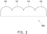
- FIG. 2 is a side view of an optical lens having a plurality of lenticular lens units with the same height.
- FIG. 3 illustrates light intensity distribution of an optical system including the optical lens in FIG. 2 .
- FIG. 4 illustrates light intensity distribution of the optical system in FIG. 1A .
- a plurality of lenticular lens units 110 of an optical lens 100a in FIG. 2 are identical, and there is no height difference between adjacent lenticular lens units 110.
- Such optical lens 100a has a common problem that the light obtained by projecting a light beam through the optical lens 100a is likely to be non-uniform in brightness.
- FIG. 3 in the light projected by an optical system including the optical lens 100a in FIG.
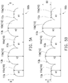
- FIG. 5A is a side view of an optical lens according to an embodiment of the disclosure.
- the optical lens 100b of the present embodiment includes a plurality of first lenticular lens units 110a and a plurality of second lenticular lens units 110b, and the first lenticular lens units 110a and the second lenticular lens units 110b are alternately arranged.
- the number of the first lenticular lens units 110a is three
- the number of the second lenticular lens units 110b is two.
- the numbers of the first lenticular lens units 110a and the second lenticular lens units 110b are not limited to the above.
- FIG. 5B is a side view of an optical lens according to an embodiment of the disclosure.
- the optical lens 100c differs from the optical lens 100 in that, the optical lens 100c of the present embodiment includes a plurality of first lenticular lens units 110a and a plurality of second lenticular lens units 110b, and the first lenticular lens units 110a and the second lenticular lens units 110b are alternately arranged.
- the first lenticular lens units 110a have the same first height H1.
- the second lenticular lens units 110b have different heights from each other.
- the second lenticular lens unit 110b closer to the left side has a second height H2
- the second lenticular lens unit 110b closer to the right side has a third height H3, wherein the second height H2 is different from the third height H3.
- the second lenticular lens unit 110b closer to the left side and the first lenticular lens unit 110a adjacent thereto has a first height difference D1 therebetween
- the second lenticular lens unit 110b closer to the right side and the first lenticular lens unit 110a adjacent thereto has a second height difference D2 therebetween, wherein the first height difference D1 is different from the second height difference D2.
- the second lenticular lens units 110b have two different heights.
- the second lenticular lens units 110b may have three, four or more different heights, and the disclosure is not limited thereto.
- FIG. 5C is a side view of an optical lens according to an embodiment of the disclosure.
- the optical lens 100d of the present embodiment includes a plurality of first lenticular lens units 110a and a plurality of second lenticular lens units 110b, and the first lenticular lens units 110a and the second lenticular lens units 110b are alternately arranged.
- the first lenticular lens units 110a have the same first width W1.
- the second lenticular lens units 110b have different widths from each other.
- the second lenticular lens unit 110b closer to the left side has a second width W2
- the second lenticular lens unit 110b closer to the right side has a third height W3, wherein the second width W2 is different from the third height W3.
- the second lenticular lens units 110b have two different widths.
- the second lenticular lens units 110b may have three, four or more different widths.
- the first lenticular lens units 110a may also have different widths from each other, and the width of the first lenticular lens units may be the same as or different from the width of the second lenticular lens units 110b. The disclosure is not limited thereto.
- FIG. 6A to FIG. 6C are schematic views illustrating a method of manufacturing an optical lens according to an embodiment of the disclosure.
- the schematic views of the manufacturing method shown in the present embodiment illustrate an example of manufacturing the optical lens 100b as shown in FIG. 5A .
- the manufacturing method shown in the present embodiment may also be used to manufacture an optical lens in a different form, such as the optical lens 100 and the optical lens 100c of the aforesaid embodiments, an optical lens having other number of lenticular lens units, or an optical lens having lenticular lens units with other different height.
- the disclosure is not limited thereto.
- a mold 200 is provided, and the mold 200 has a cavity C having a shape corresponding to the lenticular lens units 110 as shown in FIG. 5A .
- a lens material 200b is filled into the cavity C and cured.
- the cured lens material 200b is separated from the mold 200. In this way, the manufacture of the optical lens 100b is completed.
- the optical lens 100b is formed by, for example, an injection molding process. In other embodiments, the optical lens may be formed by thermoforming or other suitable optical lens manufacturing process.
- the mold 200 is made, for example, by directly cutting a mold material or by performing molding using a mold core. However, the disclosure is not limited thereto.
- FIG. 7A to FIG. 7B are schematic views illustrating a method of manufacturing the mold in FIG. 6A .
- a plurality of mold units 210, 220, 230, 240 and 250 independent of each other are provided.
- the mold units 210, 220, 230, 240 and 250 respectively have partial cavity surfaces 212, 222, 232, 242 and 252 corresponding to the lenticular lens units 110.
- the mold units 210, 220, 230, 240 and 250 are disposed side by side to constitute the mold 200.
- FIG. 8A to FIG. 8D are schematic views illustrating another method of manufacturing the mold in FIG. 6A .
- a plurality of mold core units 310, 320, 330, 340 and 350 independent of each other are provided.
- the mold core units 310, 320, 330, 340 and 350 respectively have the same shapes and sizes as the lenticular lens units 110.
- the mold core units 310, 320, 330, 340 and 350 are disposed side by side for performing molding.
- a mold material 300 is pressed onto the mold core units 310, 320, 330, 340 and 350 and cured.
- the cured mold material 300 is separated from the mold core units 310, 320, 330, 340 and 350 to complete the manufacture of the mold 200.
- a material of the mold core units 310, 320, 330, 340 and 350 includes, for example, metal or other suitable material.
- a material of the mold material 300 includes, for example, gypsum or other suitable material. The disclosure is not limited thereto.
- the mold units 210, 220, 230, 240 and 250 as well as the mold core units 310, 320, 330, 340 and 350 may be respectively independently made, and then combined with each other to obtain a required complete mold or mold core.
- the mold units or mold core units which are independently made can be combined to obtain a surface profile including a sharp ridge line or valley line.
- sharp ridge lines or valley lines may be formed at connected parts between adjacent mold units 210, 220, 230, 240 and 250 or adjacent mold core units 310, 320, 330, 340 and 350.
- each of the mold units or mold core units may be subjected to an appearance and size inspection, which facilitates easy and precise control of manufacturing accuracy of the mold units or mold core units.
- an appearance and size inspection may be carried out again thereon to ensure that the appearance and size of the entire optical lens meet the requirements.
- FIG. 9A to FIG. 9B are schematic views illustrating a method of manufacturing an optical lens according to an embodiment of the disclosure.
- a plurality of first lenticular lens units 410a and second lenticular lens units 410b independent of each other are provided.
- the number of the first lenticular lens units 410a is, for example, three, and the first lenticular lens units 410a have the same shape and size as, for example, the first lenticular lens units 110a as shown in FIG. 1A .
- the number of the second lenticular lens units 410b is, for example, two, and the second lenticular lens units 410b have the same shape and size as, for example, the second lenticular lens units 110b as shown in FIG. 1A .
- the first lenticular lens units 410a and the second lenticular lens units 410b are disposed side by side so as to be alternately arranged.
- An optically clear adhesive (OCA) is used to stick the first lenticular lens units 410a and the second lenticular lens units 410b together to form an optical lens 400.
- the manufacturing methods of an optical lens or a mold according to the embodiments of the disclosure are capable of manufacturing, for example but not limited to, any of the optical lenses of the aforesaid embodiments and the mold corresponding thereto.
- the manufacturing methods of an optical lens or a mold according to the embodiments of the disclosure are applicable to an optical lens or a mold in any form in which the formation of an ideal ridge line or valley line between any two adjacent units of the optical lens or the mold is unlikely due to the limits of processing accuracy.
- the manufacturing accuracy of the optical lens or the mold can be easily and precisely controlled, so as to form an ideal ridge line or valley line, thereby ensuring that the appearance and size of the entire optical lens meet the requirements, so that the optical lens has ideal imaging quality.
- an embodiment of the disclosure proposes an optical lens including a plurality of lenticular lens units, wherein adjacent two of the lenticular lens units have the height difference D therebetween.
- the optical lens satisfies D ⁇ 2 ln 2 ⁇ n ⁇ 2 ⁇ , wherein n represents the refractive index of the optical lens, ⁇ represents the central wavelength of the light beam, and ⁇ represents the spectral bandwidth of the light beam.
Landscapes
- Physics & Mathematics (AREA)
- General Physics & Mathematics (AREA)
- Optics & Photonics (AREA)
- Engineering & Computer Science (AREA)
- Manufacturing & Machinery (AREA)
Abstract
Description
- This application claims the priority benefit of
U.S. provisional application serial no. 62/535,221, filed on July 20, 2017 - The disclosure relates to an optical lens, an optical system and a method of manufacturing an optical lens.
- Linear light obtained by projecting laser light through a lenticular lens may be used as an emission source for optical tracking. For example, this emission source may be applied in a positioning and tracking system in virtual reality (VR). More specifically, laser light emitted by a laser light source in a base station or a lighthouse passes through a lenticular lens to form linear light, and a motor in the base station or the lighthouse having the lenticular lens mounted thereon continuously rotates to thus enable the linear light to continuously scan a specific space. A plurality of light sensors are disposed on a head mounted display (HMD) or a controller to detect the linear light emitted from the base station or the lighthouse. According to rotation angle and frequency of the motor as well as a time difference between time points at which the linear light is detected by each of the light sensors, the system can determine six-axis coordinates of the HMD or the controller in the space.
- However, in light pattern distribution of such linear light, a problem of non-uniform brightness often arises in, for example, bright regions and dark regions of the linear light. More specifically, when the dark regions of the linear light scan over the light sensors, the dark regions of the linear light may not be detected by the light sensors, and positioning accuracy is thus affected.
- The disclosure provides an optical lens causing light projected therethrough to be uniform in brightness.
- The disclosure provides an optical system projecting light which is uniform in brightness.
- The disclosure provides a method of manufacturing the aforesaid optical lens.
- An embodiment of the disclosure provides an optical lens adapted to be disposed on a transmission path of a light beam. The optical lens includes a plurality of lenticular lens units extending along the same direction, and the lenticular lens units are disposed side by side along a direction perpendicular to the extension direction thereof, wherein each of the lenticular lens units has a height relative to a bottom surface of the optical lens, adjacent two of the lenticular lens units have a height difference D therebetween, and the optical lens satisfies

- An embodiment of the disclosure provides an optical system including a light source and an optical lens. The light source is adapted to emit a light beam. The optical lens is disposed on a transmission path of the light beam. The optical lens includes a plurality of lenticular lens units extending along the same direction, and the lenticular lens units are disposed side by side along a direction perpendicular to the extension direction thereof, wherein each of the lenticular lens units has a height relative to a bottom surface of the optical lens, adjacent two of the lenticular lens units have a height difference D therebetween, and the optical lens satisfies

- An embodiment of the disclosure provides a method of manufacturing the aforesaid optical lens, the method including the following steps. A mold having a cavity having a shape corresponding to the lens units is provided. A lens material is filled into the cavity. The lens material is cured. The cured lens material is separated from the mold.
- Based on the above, an embodiment of the disclosure proposes an optical lens including a plurality of lenticular lens units, and adjacent two of the lenticular lens units have the height difference D therebetween. The optical lens satisfies

- To make the above features and advantages of the disclosure more comprehensible, examples accompanied with drawings are described in detail as follows.
-
-
FIG. 1A is a side view of an optical system according to an embodiment of the disclosure. -
FIG. 1B is a three-dimensional view of the optical system inFIG. 1A . -
FIG. 2 is a side view of an optical lens having a plurality of lenticular lens units with the same height. -
FIG. 3 illustrates light intensity distribution of an optical system including the optical lens inFIG. 2 . -
FIG. 4 illustrates light intensity distribution of the optical system inFIG. 1A . -
FIG. 5A is a side view of an optical lens according to an embodiment of the disclosure. -
FIG. 5B is a side view of an optical lens according to an embodiment of the disclosure. -
FIG. 5C is a side view of an optical lens according to an embodiment of the disclosure. -
FIG. 6A to FIG. 6C are schematic views illustrating a method of manufacturing an optical lens according to an embodiment of the disclosure. -
FIG. 7A to FIG. 7B are schematic views illustrating a method of manufacturing a mold inFIG. 6A . -
FIG. 8A to FIG. 8D are schematic views illustrating another method of manufacturing the mold inFIG. 6A . -
FIG. 9A to FIG. 9B are schematic views illustrating a method of manufacturing an optical lens according to an embodiment of the disclosure. -
FIG. 1A is a side view of an optical system according to an embodiment of the disclosure.FIG. 1B is a three-dimensional view of the optical system inFIG. 1A . As shown inFIG. 1A and FIG. 1B , anoptical system 10 of the present embodiment includes alight source 12 and anoptical lens 100. Thelight source 12 is adapted to emit a light beam L. Theoptical lens 100 is disposed on a transmission path of the light beam L. Theoptical lens 100 includes a plurality oflenticular lens units 110 extending along the same direction (for example, a direction d1 perpendicular to the drawing sheet ofFIG. 1A ), and thelenticular lens units 110 are disposed side by side along a direction (for example, a left-right direction d2 of the drawing sheet ofFIG. 1A ) perpendicular to the extension direction. In the present embodiment, a material of theoptical lens 100 includes, for example, polycarbonate (PC) or other suitable transparent material. - Specifically, the
lenticular lens units 110 of the present embodiment include two firstlenticular lens units 110a and one secondlenticular lens unit 110b, and the secondlenticular lens unit 110b is disposed between the two firstlenticular lens units 110a. - In the present embodiment, the first
lenticular lens units 110a have a firstcurved surface 112a opposing a bottom surface BS, the secondlenticular lens unit 110b has a secondcurved surface 112b opposing the bottom surface BS, and the firstcurved surface 112a and the secondcurved surface 112b have the same curvature. Thus, the firstlenticular lens units 110a and the secondlenticular lens unit 110b are similar in appearance. In other embodiments, the firstcurved surface 112a and the secondcurved surface 112b may have different curvatures, and the disclosure is not limited thereto. By controlling the curvatures of the firstcurved surface 112a and the secondcurved surface 112b, a range of light pattern distribution can be adjusted. - In the present embodiment, each of the first
lenticular lens units 110a has the same first height H1 relative to the bottom surface BS of theoptical lens 100, and the secondlenticular lens unit 110b has a second height H2 relative to the bottom surface BS of theoptical lens 100, wherein the first height H1 is different from the second height H2. Herein, the firstlenticular lens unit 110a and the secondlenticular lens unit 110b adjacent thereto have a height difference D therebetween, and theoptical lens 100 satisfies
optical lens 100, λ represents a central wavelength of the light beam L, and Δλ represents a spectral bandwidth of the light beam L. - With the above design, it can be prevented that, after the light beam L passes through two adjacent
lenticular lens units 110 with no height difference therebetween, interference occurs and affects uniformity of the light. In addition, since a distance between two identical firstlenticular lens units 110a increases and the firstlenticular lens unit 110a and the secondlenticular lens unit 110b adjacent thereto have the height difference D therebetween, in the light obtained by projecting the light beam L through theoptical lens 100, formation of dark regions with relatively low brightness can be prevented. - For example, in the case where n=1.5, λ=800 nm and Δλ=10 nm, which means that the refractive index of the
optical lens 100 is 1.5, the central wavelength of the light beam L emitted by thelight source 12 is 800 nm and the spectral bandwidth of the light beam L is 10 nm, as long as the height difference D between the firstlenticular lens unit 110a and the secondlenticular lens unit 110b adjacent thereto is greater than or equal to 34.75 µm, the formation of dark regions with relatively low brightness can be prevented in the light obtained by passing the light beam L through theoptical lens 100. - In addition, in the present embodiment, the
light source 12 is disposed on a side closer to the bottom surface BS. The light beam L emitted by thelight source 12 enters theoptical lens 100 via the bottom surface BS and exits theoptical lens 100 via the firstcurved surface 112a or the secondcurved surface 112b. In other embodiments, thelight source 12 may be disposed on a side away from the bottom surface BS. The light beam L emitted by thelight source 12 enters theoptical lens 100 via the firstcurved surface 112a or the secondcurved surface 112b and exits theoptical lens 100 via the bottom surface BS. -
FIG. 2 is a side view of an optical lens having a plurality of lenticular lens units with the same height.FIG. 3 illustrates light intensity distribution of an optical system including the optical lens inFIG. 2 .FIG. 4 illustrates light intensity distribution of the optical system inFIG. 1A . As shown inFIG. 2 , a plurality oflenticular lens units 110 of anoptical lens 100a inFIG. 2 are identical, and there is no height difference between adjacentlenticular lens units 110. Suchoptical lens 100a has a common problem that the light obtained by projecting a light beam through theoptical lens 100a is likely to be non-uniform in brightness. As shown inFIG. 3 , in the light projected by an optical system including theoptical lens 100a inFIG. 2 , there are significant differences in light intensity between different space coordinates. That is, there are apparent bright regions and dark regions in light intensity distribution, and thus an inferior light pattern distribution is provided. However, it is clear fromFIG. 3 andFIG. 4 that, compared to the case of theoptical lens 100a inFIG. 2 , the light obtained by projecting the light beam L through theoptical lens 100 inFIG. 1A shows smaller differences in light intensity between different space coordinates. That is, there are no dark regions with relatively low brightness in light pattern distribution, and thus more uniform brightness is achieved. -
FIG. 5A is a side view of an optical lens according to an embodiment of the disclosure. As shown inFIG. 5A , components and related descriptions of anoptical lens 100b of the present embodiment can be understood from theoptical lens 100 of the embodiment ofFIG. 1A , and will not be repeated herein. Theoptical lens 100b differs from theoptical lens 100 in that, theoptical lens 100b of the present embodiment includes a plurality of firstlenticular lens units 110a and a plurality of secondlenticular lens units 110b, and the firstlenticular lens units 110a and the secondlenticular lens units 110b are alternately arranged. In the present embodiment, the number of the firstlenticular lens units 110a is three, and the number of the secondlenticular lens units 110b is two. However, in other embodiments, the numbers of the firstlenticular lens units 110a and the secondlenticular lens units 110b are not limited to the above. -
FIG. 5B is a side view of an optical lens according to an embodiment of the disclosure. As shown inFIG. 5B , components and related descriptions of anoptical lens 100c of the present embodiment can be understood from theoptical lens 100 of the embodiment ofFIG. 1A , and will not be repeated herein. Theoptical lens 100c differs from theoptical lens 100 in that, theoptical lens 100c of the present embodiment includes a plurality of firstlenticular lens units 110a and a plurality of secondlenticular lens units 110b, and the firstlenticular lens units 110a and the secondlenticular lens units 110b are alternately arranged. The firstlenticular lens units 110a have the same first height H1. The secondlenticular lens units 110b have different heights from each other. For example, inFIG. 5B , the secondlenticular lens unit 110b closer to the left side has a second height H2, and the secondlenticular lens unit 110b closer to the right side has a third height H3, wherein the second height H2 is different from the third height H3. Thus, the secondlenticular lens unit 110b closer to the left side and the firstlenticular lens unit 110a adjacent thereto has a first height difference D1 therebetween, and the secondlenticular lens unit 110b closer to the right side and the firstlenticular lens unit 110a adjacent thereto has a second height difference D2 therebetween, wherein the first height difference D1 is different from the second height difference D2. In the present embodiment, the secondlenticular lens units 110b have two different heights. However, in other embodiments, the secondlenticular lens units 110b may have three, four or more different heights, and the disclosure is not limited thereto. -
FIG. 5C is a side view of an optical lens according to an embodiment of the disclosure. As shown inFIG. 5C , components and related descriptions of anoptical lens 100d of the present embodiment can be understood from theoptical lens 100 of the embodiment ofFIG. 1A , and will not be repeated herein. Theoptical lens 100d differs from theoptical lens 100 in that, theoptical lens 100d of the present embodiment includes a plurality of firstlenticular lens units 110a and a plurality of secondlenticular lens units 110b, and the firstlenticular lens units 110a and the secondlenticular lens units 110b are alternately arranged. The firstlenticular lens units 110a have the same first width W1. The secondlenticular lens units 110b have different widths from each other. For example, inFIG. 5C , the secondlenticular lens unit 110b closer to the left side has a second width W2, and the secondlenticular lens unit 110b closer to the right side has a third height W3, wherein the second width W2 is different from the third height W3. In the present embodiment, the secondlenticular lens units 110b have two different widths. However, in other embodiments, the secondlenticular lens units 110b may have three, four or more different widths. In addition, the firstlenticular lens units 110a may also have different widths from each other, and the width of the first lenticular lens units may be the same as or different from the width of the secondlenticular lens units 110b. The disclosure is not limited thereto. -
FIG. 6A to FIG. 6C are schematic views illustrating a method of manufacturing an optical lens according to an embodiment of the disclosure. The schematic views of the manufacturing method shown in the present embodiment illustrate an example of manufacturing theoptical lens 100b as shown inFIG. 5A . However, the manufacturing method shown in the present embodiment may also be used to manufacture an optical lens in a different form, such as theoptical lens 100 and theoptical lens 100c of the aforesaid embodiments, an optical lens having other number of lenticular lens units, or an optical lens having lenticular lens units with other different height. The disclosure is not limited thereto. - Firstly, as shown in
FIG. 6A , amold 200 is provided, and themold 200 has a cavity C having a shape corresponding to thelenticular lens units 110 as shown inFIG. 5A . Next, as shown inFIG. 6B , alens material 200b is filled into the cavity C and cured. Finally, as shown inFIG. 6C , the curedlens material 200b is separated from themold 200. In this way, the manufacture of theoptical lens 100b is completed. - In the present embodiment, the
optical lens 100b is formed by, for example, an injection molding process. In other embodiments, the optical lens may be formed by thermoforming or other suitable optical lens manufacturing process. In the present embodiment, themold 200 is made, for example, by directly cutting a mold material or by performing molding using a mold core. However, the disclosure is not limited thereto. -
FIG. 7A to FIG. 7B are schematic views illustrating a method of manufacturing the mold inFIG. 6A . Firstly, as shown inFIG. 7A , a plurality ofmold units mold units lenticular lens units 110. Next, as shown inFIG. 7B , themold units mold 200. -
FIG. 8A to FIG. 8D are schematic views illustrating another method of manufacturing the mold inFIG. 6A . Firstly, as shown inFIG. 8A , a plurality ofmold core units mold core units lenticular lens units 110. Next, as shown inFIG. 8B , themold core units FIG. 8C , amold material 300 is pressed onto themold core units FIG. 8D , the curedmold material 300 is separated from themold core units mold 200. - In the present embodiment, a material of the
mold core units mold material 300 includes, for example, gypsum or other suitable material. The disclosure is not limited thereto. - In the embodiments shown in
FIGs. 7A to 7B andFIGs. 8A to 8D , themold units mold core units adjacent mold units mold core units - In another respect, after the process of the respectively independent mold units or mold core units is completed, each of the mold units or mold core units may be subjected to an appearance and size inspection, which facilitates easy and precise control of manufacturing accuracy of the mold units or mold core units. In addition, after the mold units or mold core units are combined to obtain a complete mold or mold core, an appearance and size inspection may be carried out again thereon to ensure that the appearance and size of the entire optical lens meet the requirements.
-
FIG. 9A to FIG. 9B are schematic views illustrating a method of manufacturing an optical lens according to an embodiment of the disclosure. Firstly, as shown inFIG. 9A , a plurality of firstlenticular lens units 410a and secondlenticular lens units 410b independent of each other are provided. In the present embodiment, the number of the firstlenticular lens units 410a is, for example, three, and the firstlenticular lens units 410a have the same shape and size as, for example, the firstlenticular lens units 110a as shown inFIG. 1A . The number of the secondlenticular lens units 410b is, for example, two, and the secondlenticular lens units 410b have the same shape and size as, for example, the secondlenticular lens units 110b as shown inFIG. 1A . In other embodiments, there may be other numbers of firstlenticular lens units 410a and secondlenticular lens units 410b, or the firstlenticular lens units 410a and the secondlenticular lens units 410b may be in other shapes or sizes. The disclosure is not limited thereto. - Next, as shown in
FIG. 9B , the firstlenticular lens units 410a and the secondlenticular lens units 410b are disposed side by side so as to be alternately arranged. An optically clear adhesive (OCA) is used to stick the firstlenticular lens units 410a and the secondlenticular lens units 410b together to form anoptical lens 400. - It should be noted that, the manufacturing methods of an optical lens or a mold according to the embodiments of the disclosure are capable of manufacturing, for example but not limited to, any of the optical lenses of the aforesaid embodiments and the mold corresponding thereto. The manufacturing methods of an optical lens or a mold according to the embodiments of the disclosure are applicable to an optical lens or a mold in any form in which the formation of an ideal ridge line or valley line between any two adjacent units of the optical lens or the mold is unlikely due to the limits of processing accuracy.
- By providing a plurality of lenticular lens units, mold units and mold core units which are independent of each other, in the manufacturing methods of an optical lens or a mold according to the embodiments of the disclosure, the manufacturing accuracy of the optical lens or the mold can be easily and precisely controlled, so as to form an ideal ridge line or valley line, thereby ensuring that the appearance and size of the entire optical lens meet the requirements, so that the optical lens has ideal imaging quality.
- In summary, an embodiment of the disclosure proposes an optical lens including a plurality of lenticular lens units, wherein adjacent two of the lenticular lens units have the height difference D therebetween. The optical lens satisfies

- Although the disclosure has been described with reference to the above examples, it will be apparent to one of ordinary skill in the art that modifications to the described examples may be made without departing from the spirit of the disclosure. Accordingly, the scope of the disclosure will be defined by the attached claims and not by the above detailed descriptions.
Claims (14)
- An optical lens adapted to be disposed on a transmission path of a light beam, the optical lens comprising:
a plurality of lenticular lens units extending along a same direction, the lenticular lens units being disposed side by side along a direction perpendicular to the extension direction thereof, wherein each of the lenticular lens units has a height relative to a bottom surface of the optical lens, adjacent two of the lenticular lens units have a height difference D therebetween, and the optical lens satisfies
- The optical lens of claim 1, wherein the lenticular lens units comprise a plurality of first lenticular lens units and a plurality of second lenticular lens units, the first lenticular lens units and the second lenticular lens units are alternately arranged, the first lenticular lens units have a same first height and the second lenticular lens units have a same second height.
- The optical lens of claim 1, wherein the lenticular lens units comprise a plurality of first lenticular lens units and a plurality of second lenticular lens units, the first lenticular lens units and the second lenticular lens units are alternately arranged, the first lenticular lens units have a same first height and the second lenticular lens units have different heights from each other.
- The optical lens of claim 1, wherein each of the lenticular lens units has a curved surface opposing the bottom surface, and the curved surfaces have the same curvature.
- The optical lens of claim 1, wherein each of the lenticular lens units has a curved surface opposing the bottom surface, and the curved surfaces have different curvatures.
- An optical system, comprising:a light source adapted to emit a light beam; andan optical lens disposed on a transmission path of the light beam, the optical lens comprising:
a plurality of lenticular lens units extending along a same direction, the lenticular lens units being disposed side by side along a direction perpendicular to the extension direction thereof, wherein each of the lenticular lens units has a height relative to a bottom surface of the optical lens, adjacent two of the lenticular lens units have a height difference D therebetween, and the optical lens satisfies
- The optical system of claim 6, wherein the lenticular lens units of the optical lens comprise a plurality of first lenticular lens units and a plurality of second lenticular lens units, the first lenticular lens units and the second lenticular lens units are alternately arranged, the first lenticular lens units have a same first height and the second lenticular lens units have a same second height.
- The optical system of claim 6, wherein the lenticular lens units of the optical lens comprise a plurality of first lenticular lens units and a plurality of second lenticular lens units, the first lenticular lens units and the second lenticular lens units are alternately arranged, the first lenticular lens units have a same first height and the second lenticular lens unit have different heights from each other.
- The optical system of claim 6, wherein each of the lenticular lens units has a curved surface opposing the bottom surface, and the curved surfaces have the same curvature.
- The optical system of claim 6, wherein each of the lenticular lens units has a curved surface opposing the bottom surface, and the curved surfaces have different curvatures.
- A method of manufacturing the optical lens of claim 1, comprising:providing a mold, the mold having a cavity having a shape corresponding to the lenticular lens units;filling a lens material into the cavity;curing the lens material; andseparating the cured lens material from the mold.
- The method of claim 11, wherein a method of providing the mold comprises:providing a plurality of mold units independent of each other, the mold units respectively having a partial mold surface corresponding to the lenticular lens units; anddisposing the mold units side by side to constitute the mold.
- The method of claim 11, wherein a method of providing the mold comprises:providing a plurality of mold core units independent of each other, the mold core units respectively having the same shapes and sizes as the lenticular lens units;disposing the mold core units side by side, and performing molding to form the mold.
- A method of manufacturing the optical lens of claim 1, comprising:providing a plurality of lenticular lens units independent of each other; andsticking the lenticular lens units independent of each other together by using an optically clear adhesive, so as to form the optical lens.
Applications Claiming Priority (2)
| Application Number | Priority Date | Filing Date | Title |
|---|---|---|---|
| US201762535221P | 2017-07-20 | 2017-07-20 | |
| US15/896,072 US10670778B2 (en) | 2017-07-20 | 2018-02-14 | Optical lens, optical system and method of manufacturing optical lens |
Publications (2)
| Publication Number | Publication Date |
|---|---|
| EP3432040A1 true EP3432040A1 (en) | 2019-01-23 |
| EP3432040B1 EP3432040B1 (en) | 2024-06-12 |
Family
ID=62235841
Family Applications (1)
| Application Number | Title | Priority Date | Filing Date |
|---|---|---|---|
| EP18173702.4A Active EP3432040B1 (en) | 2017-07-20 | 2018-05-22 | Optical lens, optical system and method of manufacturing optical lens |
Country Status (2)
| Country | Link |
|---|---|
| US (1) | US10670778B2 (en) |
| EP (1) | EP3432040B1 (en) |
Families Citing this family (4)
| Publication number | Priority date | Publication date | Assignee | Title |
|---|---|---|---|---|
| JP7092112B2 (en) * | 2017-03-22 | 2022-06-28 | 大日本印刷株式会社 | Information recorder |
| US12411342B2 (en) | 2020-03-11 | 2025-09-09 | Hypervision Ltd | Head mounted display (HMD) apparatus, method, and system |
| CN115704929A (en) * | 2021-08-06 | 2023-02-17 | 华为技术有限公司 | Lens, laser emission system and electronics |
| KR20240074501A (en) * | 2022-11-21 | 2024-05-28 | 현대모비스 주식회사 | Lens sheet and vehicle lamp |
Citations (3)
| Publication number | Priority date | Publication date | Assignee | Title |
|---|---|---|---|---|
| EP2884332A1 (en) * | 2012-08-08 | 2015-06-17 | Sony Corporation | Display apparatus and illuminating apparatus |
| WO2016163125A1 (en) * | 2015-04-08 | 2016-10-13 | 株式会社クラレ | Composite diffusion plate |
| EP3170674A1 (en) * | 2014-07-15 | 2017-05-24 | Toppan Printing Co., Ltd. | Resin sheet and booklet |
Family Cites Families (8)
| Publication number | Priority date | Publication date | Assignee | Title |
|---|---|---|---|---|
| US6624934B1 (en) | 1999-06-18 | 2003-09-23 | 3M Innovative Properties Company | Projection screen using variable power lenticular lens for asymmetric viewing angle |
| GB0427607D0 (en) | 2004-12-16 | 2005-01-19 | Microsharp Corp Ltd | Structured optical film |
| TWI411819B (en) | 2007-04-03 | 2013-10-11 | Optivision Technology Inc | An optical film having a surface structure |
| KR101683938B1 (en) | 2009-06-02 | 2016-12-07 | 쓰리엠 이노베이티브 프로퍼티즈 컴파니 | Light redirecting film and display using this film |
| KR101330763B1 (en) * | 2011-06-29 | 2013-11-18 | 엘지이노텍 주식회사 | Lighting device |
| US9389355B2 (en) | 2012-03-20 | 2016-07-12 | 3M Innovative Properties Company | Structured optical film |
| AU2014294412B2 (en) | 2013-07-26 | 2017-08-03 | Jx Nippon Oil & Energy Corporation | Method for manufacturing substrate having textured structure |
| WO2015104968A1 (en) | 2014-01-10 | 2015-07-16 | Jx日鉱日石エネルギー株式会社 | Optical substrate, mold to be used in optical substrate manufacture, and light emitting element including optical substrate |
-
2018
- 2018-02-14 US US15/896,072 patent/US10670778B2/en active Active
- 2018-05-22 EP EP18173702.4A patent/EP3432040B1/en active Active
Patent Citations (4)
| Publication number | Priority date | Publication date | Assignee | Title |
|---|---|---|---|---|
| EP2884332A1 (en) * | 2012-08-08 | 2015-06-17 | Sony Corporation | Display apparatus and illuminating apparatus |
| EP3170674A1 (en) * | 2014-07-15 | 2017-05-24 | Toppan Printing Co., Ltd. | Resin sheet and booklet |
| WO2016163125A1 (en) * | 2015-04-08 | 2016-10-13 | 株式会社クラレ | Composite diffusion plate |
| EP3282293A1 (en) * | 2015-04-08 | 2018-02-14 | Kuraray Co., Ltd. | Composite diffusion plate |
Also Published As
| Publication number | Publication date |
|---|---|
| EP3432040B1 (en) | 2024-06-12 |
| US20190025472A1 (en) | 2019-01-24 |
| US10670778B2 (en) | 2020-06-02 |
Similar Documents
| Publication | Publication Date | Title |
|---|---|---|
| US10670778B2 (en) | Optical lens, optical system and method of manufacturing optical lens | |
| US10443811B2 (en) | Microlens array and optical system including the same | |
| CN107223207B (en) | Quality assessment device, method, system and the storage medium of optical module | |
| EP3644110B1 (en) | Optical element and optical system | |
| CN106030376B (en) | In waveguide and relevant improvement | |
| KR101945661B1 (en) | Diffusion plate | |
| KR101185616B1 (en) | Methods of cutting or forming cavities in a substrate for use in making optical films, components or wave guides | |
| KR102026005B1 (en) | Composite diffusion plate | |
| US10895759B2 (en) | Optical device and method of three-dimensional display | |
| EP2531882B1 (en) | A method of manufacturing a lens for providing an optical display | |
| KR20190010605A (en) | A waveguide for a head-up display, comprising a reflective output coupling structure | |
| EP3163333A1 (en) | Retroreflector, and stereoscopic image display device and method using same | |
| KR20140005380A (en) | Mold for forming optical sheet, and method for manufacturing mold | |
| US20170082843A1 (en) | Marker | |
| CN103080995A (en) | Light-emitting device | |
| US20210191024A1 (en) | Optical body and light emitting device | |
| IT202000003653A1 (en) | Predictive method and relative apparatus for isotropic stereolithographic 3D printing with hybrid light source at variable speed and power | |
| CN101295055A (en) | Processing method for laser processing block boundary fuzzification | |
| CN109283780B (en) | Optical lens, optical system and method for manufacturing optical lens | |
| JP5609216B2 (en) | Shape correction method for molded plastic member and shape correction device for plastic member | |
| US20250162337A1 (en) | Locally modified waveguide total thickness variation | |
| US20210164774A1 (en) | Marker | |
| JP7151256B2 (en) | Diffractive optical element, multifaceted body, inspection method for multifaceted body, light irradiation device, method for adjusting light irradiation device | |
| JP4892939B2 (en) | Backlight light guide plate for liquid crystal display device and manufacturing method thereof | |
| KR101835213B1 (en) | Light guide plate and the manufacturing apparatus therefor, Display apparatus having the light guide plate |
Legal Events
| Date | Code | Title | Description |
|---|---|---|---|
| PUAI | Public reference made under article 153(3) epc to a published international application that has entered the european phase |
Free format text: ORIGINAL CODE: 0009012 |
|
| STAA | Information on the status of an ep patent application or granted ep patent |
Free format text: STATUS: EXAMINATION IS IN PROGRESS |
|
| 17P | Request for examination filed |
Effective date: 20180522 |
|
| AK | Designated contracting states |
Kind code of ref document: A1 Designated state(s): AL AT BE BG CH CY CZ DE DK EE ES FI FR GB GR HR HU IE IS IT LI LT LU LV MC MK MT NL NO PL PT RO RS SE SI SK SM TR |
|
| AX | Request for extension of the european patent |
Extension state: BA ME |
|
| RBV | Designated contracting states (corrected) |
Designated state(s): AL AT BE BG CH CY CZ DE DK EE ES FI FR GB GR HR HU IE IS IT LI LT LU LV MC MK MT NL NO PL PT RO RS SE SI SK SM TR |
|
| RIC1 | Information provided on ipc code assigned before grant |
Ipc: G02B 27/00 20060101ALN20231212BHEP Ipc: G02B 26/10 20060101ALN20231212BHEP Ipc: G02B 3/00 20060101AFI20231212BHEP |
|
| GRAP | Despatch of communication of intention to grant a patent |
Free format text: ORIGINAL CODE: EPIDOSNIGR1 |
|
| STAA | Information on the status of an ep patent application or granted ep patent |
Free format text: STATUS: GRANT OF PATENT IS INTENDED |
|
| INTG | Intention to grant announced |
Effective date: 20240122 |
|
| RIC1 | Information provided on ipc code assigned before grant |
Ipc: G02B 27/00 20060101ALN20240111BHEP Ipc: G02B 26/10 20060101ALN20240111BHEP Ipc: G02B 3/00 20060101AFI20240111BHEP |
|
| GRAS | Grant fee paid |
Free format text: ORIGINAL CODE: EPIDOSNIGR3 |
|
| GRAA | (expected) grant |
Free format text: ORIGINAL CODE: 0009210 |
|
| STAA | Information on the status of an ep patent application or granted ep patent |
Free format text: STATUS: THE PATENT HAS BEEN GRANTED |
|
| AK | Designated contracting states |
Kind code of ref document: B1 Designated state(s): AL AT BE BG CH CY CZ DE DK EE ES FI FR GB GR HR HU IE IS IT LI LT LU LV MC MK MT NL NO PL PT RO RS SE SI SK SM TR |
|
| REG | Reference to a national code |
Ref country code: GB Ref legal event code: FG4D |
|
| REG | Reference to a national code |
Ref country code: CH Ref legal event code: EP |
|
| REG | Reference to a national code |
Ref country code: DE Ref legal event code: R096 Ref document number: 602018070462 Country of ref document: DE |
|
| REG | Reference to a national code |
Ref country code: IE Ref legal event code: FG4D |
|
| PG25 | Lapsed in a contracting state [announced via postgrant information from national office to epo] |
Ref country code: BG Free format text: LAPSE BECAUSE OF FAILURE TO SUBMIT A TRANSLATION OF THE DESCRIPTION OR TO PAY THE FEE WITHIN THE PRESCRIBED TIME-LIMIT Effective date: 20240612 |
|
| PG25 | Lapsed in a contracting state [announced via postgrant information from national office to epo] |
Ref country code: HR Free format text: LAPSE BECAUSE OF FAILURE TO SUBMIT A TRANSLATION OF THE DESCRIPTION OR TO PAY THE FEE WITHIN THE PRESCRIBED TIME-LIMIT Effective date: 20240612 Ref country code: FI Free format text: LAPSE BECAUSE OF FAILURE TO SUBMIT A TRANSLATION OF THE DESCRIPTION OR TO PAY THE FEE WITHIN THE PRESCRIBED TIME-LIMIT Effective date: 20240612 |
|
| REG | Reference to a national code |
Ref country code: LT Ref legal event code: MG9D |
|
| PG25 | Lapsed in a contracting state [announced via postgrant information from national office to epo] |
Ref country code: GR Free format text: LAPSE BECAUSE OF FAILURE TO SUBMIT A TRANSLATION OF THE DESCRIPTION OR TO PAY THE FEE WITHIN THE PRESCRIBED TIME-LIMIT Effective date: 20240913 |
|
| REG | Reference to a national code |
Ref country code: NL Ref legal event code: MP Effective date: 20240612 |
|
| PG25 | Lapsed in a contracting state [announced via postgrant information from national office to epo] |
Ref country code: ES Free format text: LAPSE BECAUSE OF FAILURE TO SUBMIT A TRANSLATION OF THE DESCRIPTION OR TO PAY THE FEE WITHIN THE PRESCRIBED TIME-LIMIT Effective date: 20240612 |
|
| PG25 | Lapsed in a contracting state [announced via postgrant information from national office to epo] |
Ref country code: LV Free format text: LAPSE BECAUSE OF FAILURE TO SUBMIT A TRANSLATION OF THE DESCRIPTION OR TO PAY THE FEE WITHIN THE PRESCRIBED TIME-LIMIT Effective date: 20240612 |
|
| PG25 | Lapsed in a contracting state [announced via postgrant information from national office to epo] |
Ref country code: NO Free format text: LAPSE BECAUSE OF FAILURE TO SUBMIT A TRANSLATION OF THE DESCRIPTION OR TO PAY THE FEE WITHIN THE PRESCRIBED TIME-LIMIT Effective date: 20240912 Ref country code: LV Free format text: LAPSE BECAUSE OF FAILURE TO SUBMIT A TRANSLATION OF THE DESCRIPTION OR TO PAY THE FEE WITHIN THE PRESCRIBED TIME-LIMIT Effective date: 20240612 Ref country code: HR Free format text: LAPSE BECAUSE OF FAILURE TO SUBMIT A TRANSLATION OF THE DESCRIPTION OR TO PAY THE FEE WITHIN THE PRESCRIBED TIME-LIMIT Effective date: 20240612 Ref country code: GR Free format text: LAPSE BECAUSE OF FAILURE TO SUBMIT A TRANSLATION OF THE DESCRIPTION OR TO PAY THE FEE WITHIN THE PRESCRIBED TIME-LIMIT Effective date: 20240913 Ref country code: FI Free format text: LAPSE BECAUSE OF FAILURE TO SUBMIT A TRANSLATION OF THE DESCRIPTION OR TO PAY THE FEE WITHIN THE PRESCRIBED TIME-LIMIT Effective date: 20240612 Ref country code: ES Free format text: LAPSE BECAUSE OF FAILURE TO SUBMIT A TRANSLATION OF THE DESCRIPTION OR TO PAY THE FEE WITHIN THE PRESCRIBED TIME-LIMIT Effective date: 20240612 Ref country code: BG Free format text: LAPSE BECAUSE OF FAILURE TO SUBMIT A TRANSLATION OF THE DESCRIPTION OR TO PAY THE FEE WITHIN THE PRESCRIBED TIME-LIMIT Effective date: 20240612 Ref country code: RS Free format text: LAPSE BECAUSE OF FAILURE TO SUBMIT A TRANSLATION OF THE DESCRIPTION OR TO PAY THE FEE WITHIN THE PRESCRIBED TIME-LIMIT Effective date: 20240912 |
|
| PG25 | Lapsed in a contracting state [announced via postgrant information from national office to epo] |
Ref country code: NL Free format text: LAPSE BECAUSE OF FAILURE TO SUBMIT A TRANSLATION OF THE DESCRIPTION OR TO PAY THE FEE WITHIN THE PRESCRIBED TIME-LIMIT Effective date: 20240612 |
|
| REG | Reference to a national code |
Ref country code: AT Ref legal event code: MK05 Ref document number: 1694730 Country of ref document: AT Kind code of ref document: T Effective date: 20240612 |
|
| PG25 | Lapsed in a contracting state [announced via postgrant information from national office to epo] |
Ref country code: NL Free format text: LAPSE BECAUSE OF FAILURE TO SUBMIT A TRANSLATION OF THE DESCRIPTION OR TO PAY THE FEE WITHIN THE PRESCRIBED TIME-LIMIT Effective date: 20240612 |
|
| PG25 | Lapsed in a contracting state [announced via postgrant information from national office to epo] |
Ref country code: PT Free format text: LAPSE BECAUSE OF FAILURE TO SUBMIT A TRANSLATION OF THE DESCRIPTION OR TO PAY THE FEE WITHIN THE PRESCRIBED TIME-LIMIT Effective date: 20241014 |
|
| PG25 | Lapsed in a contracting state [announced via postgrant information from national office to epo] |
Ref country code: PT Free format text: LAPSE BECAUSE OF FAILURE TO SUBMIT A TRANSLATION OF THE DESCRIPTION OR TO PAY THE FEE WITHIN THE PRESCRIBED TIME-LIMIT Effective date: 20241014 |
|
| PG25 | Lapsed in a contracting state [announced via postgrant information from national office to epo] |
Ref country code: PL Free format text: LAPSE BECAUSE OF FAILURE TO SUBMIT A TRANSLATION OF THE DESCRIPTION OR TO PAY THE FEE WITHIN THE PRESCRIBED TIME-LIMIT Effective date: 20240612 |
|
| PG25 | Lapsed in a contracting state [announced via postgrant information from national office to epo] |
Ref country code: EE Free format text: LAPSE BECAUSE OF FAILURE TO SUBMIT A TRANSLATION OF THE DESCRIPTION OR TO PAY THE FEE WITHIN THE PRESCRIBED TIME-LIMIT Effective date: 20240612 |
|
| PG25 | Lapsed in a contracting state [announced via postgrant information from national office to epo] |
Ref country code: AT Free format text: LAPSE BECAUSE OF FAILURE TO SUBMIT A TRANSLATION OF THE DESCRIPTION OR TO PAY THE FEE WITHIN THE PRESCRIBED TIME-LIMIT Effective date: 20240612 Ref country code: IS Free format text: LAPSE BECAUSE OF FAILURE TO SUBMIT A TRANSLATION OF THE DESCRIPTION OR TO PAY THE FEE WITHIN THE PRESCRIBED TIME-LIMIT Effective date: 20241012 |
|
| PG25 | Lapsed in a contracting state [announced via postgrant information from national office to epo] |
Ref country code: CZ Free format text: LAPSE BECAUSE OF FAILURE TO SUBMIT A TRANSLATION OF THE DESCRIPTION OR TO PAY THE FEE WITHIN THE PRESCRIBED TIME-LIMIT Effective date: 20240612 |
|
| PG25 | Lapsed in a contracting state [announced via postgrant information from national office to epo] |
Ref country code: SK Free format text: LAPSE BECAUSE OF FAILURE TO SUBMIT A TRANSLATION OF THE DESCRIPTION OR TO PAY THE FEE WITHIN THE PRESCRIBED TIME-LIMIT Effective date: 20240612 Ref country code: RO Free format text: LAPSE BECAUSE OF FAILURE TO SUBMIT A TRANSLATION OF THE DESCRIPTION OR TO PAY THE FEE WITHIN THE PRESCRIBED TIME-LIMIT Effective date: 20240612 |
|
| PG25 | Lapsed in a contracting state [announced via postgrant information from national office to epo] |
Ref country code: SM Free format text: LAPSE BECAUSE OF FAILURE TO SUBMIT A TRANSLATION OF THE DESCRIPTION OR TO PAY THE FEE WITHIN THE PRESCRIBED TIME-LIMIT Effective date: 20240612 |
|
| PG25 | Lapsed in a contracting state [announced via postgrant information from national office to epo] |
Ref country code: SM Free format text: LAPSE BECAUSE OF FAILURE TO SUBMIT A TRANSLATION OF THE DESCRIPTION OR TO PAY THE FEE WITHIN THE PRESCRIBED TIME-LIMIT Effective date: 20240612 Ref country code: SK Free format text: LAPSE BECAUSE OF FAILURE TO SUBMIT A TRANSLATION OF THE DESCRIPTION OR TO PAY THE FEE WITHIN THE PRESCRIBED TIME-LIMIT Effective date: 20240612 Ref country code: RO Free format text: LAPSE BECAUSE OF FAILURE TO SUBMIT A TRANSLATION OF THE DESCRIPTION OR TO PAY THE FEE WITHIN THE PRESCRIBED TIME-LIMIT Effective date: 20240612 Ref country code: PL Free format text: LAPSE BECAUSE OF FAILURE TO SUBMIT A TRANSLATION OF THE DESCRIPTION OR TO PAY THE FEE WITHIN THE PRESCRIBED TIME-LIMIT Effective date: 20240612 Ref country code: IS Free format text: LAPSE BECAUSE OF FAILURE TO SUBMIT A TRANSLATION OF THE DESCRIPTION OR TO PAY THE FEE WITHIN THE PRESCRIBED TIME-LIMIT Effective date: 20241012 Ref country code: EE Free format text: LAPSE BECAUSE OF FAILURE TO SUBMIT A TRANSLATION OF THE DESCRIPTION OR TO PAY THE FEE WITHIN THE PRESCRIBED TIME-LIMIT Effective date: 20240612 Ref country code: CZ Free format text: LAPSE BECAUSE OF FAILURE TO SUBMIT A TRANSLATION OF THE DESCRIPTION OR TO PAY THE FEE WITHIN THE PRESCRIBED TIME-LIMIT Effective date: 20240612 Ref country code: AT Free format text: LAPSE BECAUSE OF FAILURE TO SUBMIT A TRANSLATION OF THE DESCRIPTION OR TO PAY THE FEE WITHIN THE PRESCRIBED TIME-LIMIT Effective date: 20240612 |
|
| PG25 | Lapsed in a contracting state [announced via postgrant information from national office to epo] |
Ref country code: IT Free format text: LAPSE BECAUSE OF FAILURE TO SUBMIT A TRANSLATION OF THE DESCRIPTION OR TO PAY THE FEE WITHIN THE PRESCRIBED TIME-LIMIT Effective date: 20240612 |
|
| REG | Reference to a national code |
Ref country code: DE Ref legal event code: R097 Ref document number: 602018070462 Country of ref document: DE |
|
| PG25 | Lapsed in a contracting state [announced via postgrant information from national office to epo] |
Ref country code: DK Free format text: LAPSE BECAUSE OF FAILURE TO SUBMIT A TRANSLATION OF THE DESCRIPTION OR TO PAY THE FEE WITHIN THE PRESCRIBED TIME-LIMIT Effective date: 20240612 |
|
| PLBE | No opposition filed within time limit |
Free format text: ORIGINAL CODE: 0009261 |
|
| STAA | Information on the status of an ep patent application or granted ep patent |
Free format text: STATUS: NO OPPOSITION FILED WITHIN TIME LIMIT |
|
| 26N | No opposition filed |
Effective date: 20250313 |
|
| PG25 | Lapsed in a contracting state [announced via postgrant information from national office to epo] |
Ref country code: SE Free format text: LAPSE BECAUSE OF FAILURE TO SUBMIT A TRANSLATION OF THE DESCRIPTION OR TO PAY THE FEE WITHIN THE PRESCRIBED TIME-LIMIT Effective date: 20240612 |
|
| REG | Reference to a national code |
Ref country code: CH Ref legal event code: H13 Free format text: ST27 STATUS EVENT CODE: U-0-0-H10-H13 (AS PROVIDED BY THE NATIONAL OFFICE) Effective date: 20251223 |
|
| PG25 | Lapsed in a contracting state [announced via postgrant information from national office to epo] |
Ref country code: LU Free format text: LAPSE BECAUSE OF NON-PAYMENT OF DUE FEES Effective date: 20250522 |
|
| PG25 | Lapsed in a contracting state [announced via postgrant information from national office to epo] |
Ref country code: CH Free format text: LAPSE BECAUSE OF NON-PAYMENT OF DUE FEES Effective date: 20250531 |
|
| REG | Reference to a national code |
Ref country code: BE Ref legal event code: MM Effective date: 20250531 |
|
| PG25 | Lapsed in a contracting state [announced via postgrant information from national office to epo] |
Ref country code: MC Free format text: LAPSE BECAUSE OF FAILURE TO SUBMIT A TRANSLATION OF THE DESCRIPTION OR TO PAY THE FEE WITHIN THE PRESCRIBED TIME-LIMIT Effective date: 20240612 |
|
| PGFP | Annual fee paid to national office [announced via postgrant information from national office to epo] |
Ref country code: GB Payment date: 20260312 Year of fee payment: 9 |
|
| PG25 | Lapsed in a contracting state [announced via postgrant information from national office to epo] |
Ref country code: IE Free format text: LAPSE BECAUSE OF NON-PAYMENT OF DUE FEES Effective date: 20250522 |
|
| PG25 | Lapsed in a contracting state [announced via postgrant information from national office to epo] |
Ref country code: BE Free format text: LAPSE BECAUSE OF NON-PAYMENT OF DUE FEES Effective date: 20250531 |
|
| PG25 | Lapsed in a contracting state [announced via postgrant information from national office to epo] |
Ref country code: LT Free format text: LAPSE BECAUSE OF FAILURE TO SUBMIT A TRANSLATION OF THE DESCRIPTION OR TO PAY THE FEE WITHIN THE PRESCRIBED TIME-LIMIT Effective date: 20240612 |
|
| PGFP | Annual fee paid to national office [announced via postgrant information from national office to epo] |
Ref country code: DE Payment date: 20260324 Year of fee payment: 9 |
|
| PGFP | Annual fee paid to national office [announced via postgrant information from national office to epo] |
Ref country code: FR Payment date: 20260401 Year of fee payment: 9 |
|
| PG25 | Lapsed in a contracting state [announced via postgrant information from national office to epo] |
Ref country code: CY Free format text: LAPSE BECAUSE OF FAILURE TO SUBMIT A TRANSLATION OF THE DESCRIPTION OR TO PAY THE FEE WITHIN THE PRESCRIBED TIME-LIMIT Effective date: 20240612 |