EP3432013A1 - System for diagnosing insulating element in bms - Google Patents
System for diagnosing insulating element in bms Download PDFInfo
- Publication number
- EP3432013A1 EP3432013A1 EP17873081.8A EP17873081A EP3432013A1 EP 3432013 A1 EP3432013 A1 EP 3432013A1 EP 17873081 A EP17873081 A EP 17873081A EP 3432013 A1 EP3432013 A1 EP 3432013A1
- Authority
- EP
- European Patent Office
- Prior art keywords
- insulation element
- comparing
- voltage region
- bms
- signal
- Prior art date
- Legal status (The legal status is an assumption and is not a legal conclusion. Google has not performed a legal analysis and makes no representation as to the accuracy of the status listed.)
- Granted
Links
Images


Classifications
-
- G—PHYSICS
- G01—MEASURING; TESTING
- G01R—MEASURING ELECTRIC VARIABLES; MEASURING MAGNETIC VARIABLES
- G01R31/00—Arrangements for testing electric properties; Arrangements for locating electric faults; Arrangements for electrical testing characterised by what is being tested not provided for elsewhere
- G01R31/12—Testing dielectric strength or breakdown voltage ; Testing or monitoring effectiveness or level of insulation, e.g. of a cable or of an apparatus, for example using partial discharge measurements; Electrostatic testing
- G01R31/1227—Testing dielectric strength or breakdown voltage ; Testing or monitoring effectiveness or level of insulation, e.g. of a cable or of an apparatus, for example using partial discharge measurements; Electrostatic testing of components, parts or materials
-
- G—PHYSICS
- G01—MEASURING; TESTING
- G01R—MEASURING ELECTRIC VARIABLES; MEASURING MAGNETIC VARIABLES
- G01R31/00—Arrangements for testing electric properties; Arrangements for locating electric faults; Arrangements for electrical testing characterised by what is being tested not provided for elsewhere
- G01R31/12—Testing dielectric strength or breakdown voltage ; Testing or monitoring effectiveness or level of insulation, e.g. of a cable or of an apparatus, for example using partial discharge measurements; Electrostatic testing
-
- G—PHYSICS
- G01—MEASURING; TESTING
- G01R—MEASURING ELECTRIC VARIABLES; MEASURING MAGNETIC VARIABLES
- G01R31/00—Arrangements for testing electric properties; Arrangements for locating electric faults; Arrangements for electrical testing characterised by what is being tested not provided for elsewhere
- G01R31/12—Testing dielectric strength or breakdown voltage ; Testing or monitoring effectiveness or level of insulation, e.g. of a cable or of an apparatus, for example using partial discharge measurements; Electrostatic testing
- G01R31/14—Circuits therefor, e.g. for generating test voltages, sensing circuits
-
- G—PHYSICS
- G01—MEASURING; TESTING
- G01R—MEASURING ELECTRIC VARIABLES; MEASURING MAGNETIC VARIABLES
- G01R31/00—Arrangements for testing electric properties; Arrangements for locating electric faults; Arrangements for electrical testing characterised by what is being tested not provided for elsewhere
- G01R31/36—Arrangements for testing, measuring or monitoring the electrical condition of accumulators or electric batteries, e.g. capacity or state of charge [SoC]
- G01R31/3644—Constructional arrangements
- G01R31/3648—Constructional arrangements comprising digital calculation means, e.g. for performing an algorithm
-
- G—PHYSICS
- G01—MEASURING; TESTING
- G01R—MEASURING ELECTRIC VARIABLES; MEASURING MAGNETIC VARIABLES
- G01R31/00—Arrangements for testing electric properties; Arrangements for locating electric faults; Arrangements for electrical testing characterised by what is being tested not provided for elsewhere
- G01R31/36—Arrangements for testing, measuring or monitoring the electrical condition of accumulators or electric batteries, e.g. capacity or state of charge [SoC]
- G01R31/382—Arrangements for monitoring battery or accumulator variables, e.g. SoC
Definitions
- the present invention relates to a system for diagnosing an insulation element within a battery management system (BMS), and more particularly, to a system for diagnosing an insulation element within a BMS, in which when abnormality of an insulation element dividing a BMS according to a voltage region is diagnosed, an input terminal and an output terminal of an insulation element obtain a battery pack diagnosis signal that is output through a battery monitoring circuit and passes through the insulation element, and then abnormality of the insulation element is diagnosed based on a bit operation value of the obtained battery pack diagnosis signal, or an input terminal and an output terminal of the insulation element obtain a transceived communication signal and then abnormality of the insulation element is diagnosed based on a bit operation value of the obtained transceived communication signal.
- BMS battery management system
- a battery management system applied to an electric vehicle is connected with a battery pack including a plurality of battery cells to manage various battery states of the battery pack.
- the BMS may be generally divided into a high-voltage region that is connected with a battery cell and senses a voltage of the battery cell, and a low-voltage region that is connected with a vehicle, and in this case, the high-voltage region and the low-voltage region maintain an insulation state by means of an insulation element interposed therebetween.
- various diagnosis information about the battery cell sensed in the high-voltage region may be transmitted to an operation processing unit (micro controller unit (MCU)) positioned in the low-voltage region through the insulation element.
- MCU micro controller unit
- an erroneous operation of the BMS such as the opening of a contactor
- the opening of a contactor may be caused due to a generation of a problem in the transmitted various diagnosis information of the battery cell, and there is no technology for autonomously diagnosing the generation of abnormality of the insulation element, so that actually, there is a problem in stability, such as explosion of a battery pack, due to a failure of the reception of a diagnosis result.
- the present inventors developed a system for diagnosing an insulation element within a BMS, in which an input terminal and an output terminal of an insulation element obtain a battery pack diagnosis signal that is output through a battery monitoring circuit and passes through the insulation element, and then abnormality of the insulation element is diagnosed based on a bit operation value of the obtained battery pack diagnosis signal, or an input terminal and an output terminal of the insulation element obtain a transceived communication signal and then abnormality of the insulation element is diagnosed based on a bit operation value of the obtained transceived communication signal.
- the present invention is conceived to solve the foregoing problems, and an object of the present invention is to provide a system for diagnosing an insulation element within a battery management system (BMS) in which when abnormality of an insulation element dividing a BMS according to a voltage region is diagnosed, an input terminal and an output terminal of an insulation element obtain a battery pack diagnosis signal that is output through a battery monitoring circuit and passes through the insulation element, and then abnormality of the insulation element is diagnosed based on a bit operation value of the obtained battery pack diagnosis signal, or an input terminal and an output terminal of the insulation element obtain a transceived communication signal and then abnormality of the insulation element is diagnosed based on a bit operation value of the obtained transceived communication signal.
- BMS battery management system
- An exemplary embodiment of the present invention provides a system for diagnosing an insulation element within a battery management system (BMS), the system including: in a BMS divided into a first voltage region and a second voltage region by an insulation element, a comparing unit which compares an input signal input through an input terminal of the insulation element in the first voltage region with an output signal output to the second voltage region through an output terminal of the insulation element and then outputs a comparison result; and first and second operation units which determine whether the insulation element is erroneously operated based on the comparison result.
- BMS battery management system
- the comparing unit may include at least one of a first comparing unit which compares a front-end battery diagnosis signal input through the input terminal of the insulation element in the first voltage region with a rear-end battery diagnosis signal output to the second voltage region through the output terminal of the insulation element and then provides a first operation unit within the BMS with a comparison result, and a second comparing unit which compares a communication signal for transmission transmitted from the first voltage region to the second voltage region through the insulation element with a communication signal for reception transmitted from the second voltage region to the first voltage region through the insulation element and then provides the second operation unit within the BMS with a comparison result.
- the first comparing unit may include at least one of: a first differential amplifying and comparing device which amplifies a difference between the obtained front-end battery diagnosis signal and the obtained rear-end battery diagnosis signal and then provides the first operation unit with an amplified result value; and a first adding and comparing device which adds a bit value of the obtained front-end battery diagnosis signal and a bit value of the obtained rear-end battery diagnosis signal and then provides the first operation unit with an added result value.
- the first differential amplifying and comparing device may be a differential amplifier (operational amplifier (OP AMP)) and the first adding and comparing device may be an XOR gate, and the bit value of the obtained front-end battery diagnosis signal and the bit value of the obtained rear-end battery diagnosis signal may be added by using an XOR gate circuit.
- OP AMP operational amplifier
- the first operation unit may determine that the insulation element is erroneously operated.
- the first operation unit may determine that the insulation element is erroneously operated.
- the second comparing unit may include: a second differential amplifying and comparing device which amplifies a difference between a communication signal for front-end transmission obtained through the input terminal of the insulation element and a communication signal for rear-end transmission obtained through the output terminal of the insulation element among the communication signals for transmission and then outputs an amplified result value; a third differential amplifying and comparing device which amplifies a difference between a communication signal for front-end reception obtained through the input terminal of the insulation element and a communication signal for rear-end reception obtained through the output terminal of the insulation element among the communication signals for reception and then outputs an amplified result value; and a second adding and comparing device which OR-operates the result value output from each of the second and third differential amplifying and comparing devices and then provides the second operation unit with an operated result value.
- the second and third differential amplifying and comparing devices may be differential amplifiers (OP AMPs), and the second adding and comparing device may be an OR gate.
- OP AMPs differential amplifiers
- OR gate an OR gate
- the second operation unit may determine that the insulation element may be erroneously operated.
- an input terminal and an output terminal of an insulation element obtain a battery pack diagnosis signal that is output through a battery monitoring circuit and passes through the insulation element, and then abnormality of the insulation element is diagnosed based on a bit operation value of the obtained battery pack diagnosis signal, or an input terminal and an output terminal of the insulation element obtain a transceived communication signal and then abnormality of the insulation element is diagnosed based on a bit operation value of the obtained transceived communication signal, so that there is an advantage in that it is possible to diagnose the generation of abnormality of a communication function by using the insulation element in advance and improve stability of an operation of the BMS.
- FIG. 1 is a diagram schematically illustrating a configuration of a battery management system (BMS) 2 to which a system 100 for diagnosing an insulation element within a BMS according to an exemplary embodiment of the present invention is applied
- FIG. 2 is a diagram illustrating an exemplary embodiment of the system 100 for diagnosing an insulation element within a BMS illustrated in FIG. 1 .
- BMS battery management system
- the system 100 for diagnosing an insulation element within a BMS according to the present invention may be provided inside the BMS 2 which obtains voltage information, temperature information, and the like of each battery cell 1a from a battery pack 1.
- the BMS 2 may be generally divided into a first region and a second region through an insulation element 4, and in this case, the first region may mean a high-voltage region in which a battery monitoring circuit 3 is provided, and may mean a low-voltage region in which a comparing device 110, a first operation unit 120, a second operation unit 130, a controller 5, and the like according to the present invention are provided.
- the first operation unit may be a central processing unit (micro controller unit (MCU)) which is capable of wirelessly communicating with the battery monitoring circuit 3, and the second operation unit 130 may mean a safe central processing unit (safe microcontroller unit) which receives a battery pack diagnosis signal from the battery monitoring circuit 3.
- MCU micro controller unit
- safe microcontroller unit safe central processing unit
- the BMS 2 may be divided into the first region and the second region through the insulation element 4, the first region and the second region may correspond to insulation states, and all of various information about the battery cell 1a provided from the battery monitoring circuit 3 or a communication signal for communication with the first operation unit 120 may be transmitted from the first region to the second region, or from the second region to the first region through the insulation element 4.
- system 100 for diagnosing an insulation element within a BMS may have the configurations through various exemplary embodiments as illustrated in FIGS. 2 to 4 , so that the system 100 will be described in more detail with reference to FIGS. 2 to 4 .
- FIG. 2 is a diagram illustrating an exemplary embodiment of the system 100 for diagnosing an insulation element within a BMS illustrated in FIG. 1
- FIG. 3 is a diagram illustrating a configuration of a system 100' for diagnosing an insulation element within a BMS implemented through another exemplary embodiment of the system 100 for diagnosing an insulation element within a BMS illustrated in FIG. 2
- FIG. 4 is a diagram illustrating a configuration of a system 100" for diagnosing an insulation element within a BMS implemented through another exemplary embodiment of the system 100 and 100' for diagnosing an insulation element within a BMS illustrated in FIGS. 2 and 3 .
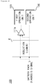
- the comparing device 110 of the system 100 for diagnosing an insulation element within a BMS illustrated in FIG. 2 may include a first comparing unit 111 which compares a front-end battery diagnosis signal input through an input terminal of the insulation element 4 in a first voltage region with a rear-end battery diagnosis signal output to a second voltage region through an output terminal of the insulation element 4, and then provides the first operation unit 120 with a comparison result.
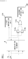
- the first comparing unit 111 may include a first differential amplifying and comparing device 111a which amplifies a difference between the obtained front-end battery diagnosis signal and the obtained rear-end battery diagnosis signal and then provides the first operation unit 120 with an amplified result value, or a first adding and comparing device 111b which adds a bit value of the obtained front-end battery diagnosis signal and a bit value of the obtained rear-end battery diagnosis signal and provides the first operation unit 120 with a result value of the addition as illustrated in FIG. 3 .
- a first differential amplifying and comparing device 111a which amplifies a difference between the obtained front-end battery diagnosis signal and the obtained rear-end battery diagnosis signal and then provides the first operation unit 120 with an amplified result value
- a first adding and comparing device 111b which adds a bit value of the obtained front-end battery diagnosis signal and a bit value of the obtained rear-end battery diagnosis signal and provides the first operation unit 120 with a result value of the addition as illustrated in FIG. 3 .
- the system 100 of FIG. 2 has the same configuration as that of FIG. 3 , but the first adding and comparing device 111b may be applied instead of the first differential amplifying and comparing device 111a of FIG. 2 .
- the first differential amplifying and comparing device 111a may mean a general differential amplifier (operational amplifier (OP AMP)), and the first adding and comparing device 111b may mean an exclusive OR gate (XOR gate).
- OP AMP operational amplifier
- XOR gate exclusive OR gate
- the first differential amplifying and comparing device 111a may serve to amplify a difference between a front-end battery diagnosis signal and a rear-end battery diagnosis signal and then transmit the amplified value to the first operation unit 120, and when the result value amplified through the first differential amplifying and comparing device 111a is less than a specific threshold value, the first operation unit 120 determines that abnormality is generated in the insulation element 4.
- the case where the result value amplified through the first differential amplifying and comparing device 111a is less than the specific threshold value means that there is no difference in a voltage between the first voltage region that is an input terminal side of the insulation element and the second voltage region that is an output terminal side of the insulation element, and may mean that the insulation is not properly performed, so that the first differential amplifying and comparing device 111a may be applied for detecting the improper insulation.
- the first adding and comparing device 111b XOR-operates a low bit (0) and a high bit (1) that are bit values of the front-end battery diagnosis signal and a low bit (0) and a high bit (1) that are bit values of the rear-end battery diagnosis signal, so that when a result value of the operation is the high bit value corresponding to 1, it is determined that abnormality is generated in the insulation element 4.
- a system 100" for diagnosing an insulation element within a BMS illustrated in FIG. 4 may include a second comparing unit 112 which compares a communication signal TX for transmission transmitted from the first voltage region to the second voltage region through the insulation element with a communication signal RX for reception transmitted from the second voltage region to the first voltage region through the insulation element, and then provides the second operation unit 130 with a comparison result, instead of the first differential amplifying and comparing device 111a and the first adding and comparing device 111b included in FIGS. 2 and 3 .
- the second comparing unit 112 may include a second differential amplifying and comparing device 112a which amplifies a difference between a communication signal for front-end transmission obtained through the input terminal of the insulation element 4 and a communication signal for rear-end transmission obtained through the output terminal of the insulation element 4 among the communication signals for transmission transmitted to from the first voltage region to the first operation unit 120 through the insulation element 4 and then outputs an amplified result value, a third differential amplifying and comparing device 112b which amplifies a difference between a communication signal for front-end reception obtained through the input terminal of the insulation element 4 (herein, the input terminal may mean the output terminal through which the communication signal for rear-end transmission is output) and a communication signal for rear-end reception obtained through the output terminal of the insulation element 4 (herein, the output terminal may mean the input terminal to which the communication signal for front-end transmission is input) among the communication signals for transmission transmitted from the second voltage region to the first voltage region through the insulation element 4 and then outputs an amplified result value, and a second adding
- the second and third differential amplifying and comparing devices 112a and 112b may be differential amplifiers (OP AMPs), and the second adding and comparing device 112c may be an OR gate.
- OP AMPs differential amplifiers
- the second adding and comparing device 112c may be an OR gate.
- the second and third differential amplifying and comparing devices 112a and 112b amplify the difference between the communication signal for front-end transmission and the communication signal for rear-end transmission and the difference between the communication signal for front-end reception and the communication signal for rear-end reception, respectively, and then transmit the amplified values to the second adding and comparing unit 112c.
- the second adding and comparing device 112c OR-operates the bit values of the amplified values and determines that abnormality is generated in the insulation element 4 when a result value of the operation is the high bit value corresponding to 1.
Landscapes
- Physics & Mathematics (AREA)
- General Physics & Mathematics (AREA)
- Secondary Cells (AREA)
- Tests Of Electric Status Of Batteries (AREA)
- Charge And Discharge Circuits For Batteries Or The Like (AREA)
- Testing Electric Properties And Detecting Electric Faults (AREA)
- Electric Propulsion And Braking For Vehicles (AREA)
Abstract
Description
- This application claims priority to and the benefit of Korean Patent Application No.
10-2016-0158504 - The present invention relates to a system for diagnosing an insulation element within a battery management system (BMS), and more particularly, to a system for diagnosing an insulation element within a BMS, in which when abnormality of an insulation element dividing a BMS according to a voltage region is diagnosed, an input terminal and an output terminal of an insulation element obtain a battery pack diagnosis signal that is output through a battery monitoring circuit and passes through the insulation element, and then abnormality of the insulation element is diagnosed based on a bit operation value of the obtained battery pack diagnosis signal, or an input terminal and an output terminal of the insulation element obtain a transceived communication signal and then abnormality of the insulation element is diagnosed based on a bit operation value of the obtained transceived communication signal.
- In general, a battery management system (BMS) applied to an electric vehicle is connected with a battery pack including a plurality of battery cells to manage various battery states of the battery pack.
- In this case, the BMS may be generally divided into a high-voltage region that is connected with a battery cell and senses a voltage of the battery cell, and a low-voltage region that is connected with a vehicle, and in this case, the high-voltage region and the low-voltage region maintain an insulation state by means of an insulation element interposed therebetween.
- Further, various diagnosis information about the battery cell sensed in the high-voltage region may be transmitted to an operation processing unit (micro controller unit (MCU)) positioned in the low-voltage region through the insulation element. In this case, when abnormality is generated in the insulation element, an erroneous operation of the BMS, such as the opening of a contactor, may be caused due to a generation of a problem in the transmitted various diagnosis information of the battery cell, and there is no technology for autonomously diagnosing the generation of abnormality of the insulation element, so that actually, there is a problem in stability, such as explosion of a battery pack, due to a failure of the reception of a diagnosis result.
- In this respect, in order to solve the problems and the limits of the insulation element to which the BMS is applied in the related art, the present inventors developed a system for diagnosing an insulation element within a BMS, in which an input terminal and an output terminal of an insulation element obtain a battery pack diagnosis signal that is output through a battery monitoring circuit and passes through the insulation element, and then abnormality of the insulation element is diagnosed based on a bit operation value of the obtained battery pack diagnosis signal, or an input terminal and an output terminal of the insulation element obtain a transceived communication signal and then abnormality of the insulation element is diagnosed based on a bit operation value of the obtained transceived communication signal.
- The present invention is conceived to solve the foregoing problems, and an object of the present invention is to provide a system for diagnosing an insulation element within a battery management system (BMS) in which when abnormality of an insulation element dividing a BMS according to a voltage region is diagnosed, an input terminal and an output terminal of an insulation element obtain a battery pack diagnosis signal that is output through a battery monitoring circuit and passes through the insulation element, and then abnormality of the insulation element is diagnosed based on a bit operation value of the obtained battery pack diagnosis signal, or an input terminal and an output terminal of the insulation element obtain a transceived communication signal and then abnormality of the insulation element is diagnosed based on a bit operation value of the obtained transceived communication signal.
- An exemplary embodiment of the present invention provides a system for diagnosing an insulation element within a battery management system (BMS), the system including: in a BMS divided into a first voltage region and a second voltage region by an insulation element, a comparing unit which compares an input signal input through an input terminal of the insulation element in the first voltage region with an output signal output to the second voltage region through an output terminal of the insulation element and then outputs a comparison result; and first and second operation units which determine whether the insulation element is erroneously operated based on the comparison result.
- In the exemplary embodiment, the comparing unit may include at least one of a first comparing unit which compares a front-end battery diagnosis signal input through the input terminal of the insulation element in the first voltage region with a rear-end battery diagnosis signal output to the second voltage region through the output terminal of the insulation element and then provides a first operation unit within the BMS with a comparison result, and a second comparing unit which compares a communication signal for transmission transmitted from the first voltage region to the second voltage region through the insulation element with a communication signal for reception transmitted from the second voltage region to the first voltage region through the insulation element and then provides the second operation unit within the BMS with a comparison result.
- In the exemplary embodiment, the first comparing unit may include at least one of: a first differential amplifying and comparing device which amplifies a difference between the obtained front-end battery diagnosis signal and the obtained rear-end battery diagnosis signal and then provides the first operation unit with an amplified result value; and a first adding and comparing device which adds a bit value of the obtained front-end battery diagnosis signal and a bit value of the obtained rear-end battery diagnosis signal and then provides the first operation unit with an added result value.
- In the exemplary embodiment, the first differential amplifying and comparing device may be a differential amplifier (operational amplifier (OP AMP)) and the first adding and comparing device may be an XOR gate, and the bit value of the obtained front-end battery diagnosis signal and the bit value of the obtained rear-end battery diagnosis signal may be added by using an XOR gate circuit.
- In the exemplary embodiment, when the result value amplified by the first differential amplifying and comparing device is less than a specific threshold value, the first operation unit may determine that the insulation element is erroneously operated.
- In the exemplary embodiment, when the result value added by the first adding and comparing device corresponds to a high bit value corresponding to 1, the first operation unit may determine that the insulation element is erroneously operated.
- In the exemplary embodiment, the second comparing unit may include: a second differential amplifying and comparing device which amplifies a difference between a communication signal for front-end transmission obtained through the input terminal of the insulation element and a communication signal for rear-end transmission obtained through the output terminal of the insulation element among the communication signals for transmission and then outputs an amplified result value; a third differential amplifying and comparing device which amplifies a difference between a communication signal for front-end reception obtained through the input terminal of the insulation element and a communication signal for rear-end reception obtained through the output terminal of the insulation element among the communication signals for reception and then outputs an amplified result value; and a second adding and comparing device which OR-operates the result value output from each of the second and third differential amplifying and comparing devices and then provides the second operation unit with an operated result value.
- In the exemplary embodiment, the second and third differential amplifying and comparing devices may be differential amplifiers (OP AMPs), and the second adding and comparing device may be an OR gate.
- In the exemplary embodiment, when the result value OR-operated by the second adding and comparing device corresponds to a high bit value corresponding to 1, the second operation unit may determine that the insulation element may be erroneously operated.
- According to one aspect of the present invention, an input terminal and an output terminal of an insulation element obtain a battery pack diagnosis signal that is output through a battery monitoring circuit and passes through the insulation element, and then abnormality of the insulation element is diagnosed based on a bit operation value of the obtained battery pack diagnosis signal, or an input terminal and an output terminal of the insulation element obtain a transceived communication signal and then abnormality of the insulation element is diagnosed based on a bit operation value of the obtained transceived communication signal, so that there is an advantage in that it is possible to diagnose the generation of abnormality of a communication function by using the insulation element in advance and improve stability of an operation of the BMS.
-
-
FIG. 1 is a diagram schematically illustrating a configuration of a battery management system (BMS) 2 to which asystem 100 for diagnosing an insulation element within a BMS according to an exemplary embodiment of the present invention is applied. -
FIG. 2 is a diagram illustrating an exemplary embodiment of thesystem 100 for diagnosing an insulation element within a BMS illustrated inFIG. 1 . -
FIG. 3 is a diagram illustrating a configuration of a system 100' for diagnosing an insulation element within a BMS implemented through another exemplary embodiment of thesystem 100 for diagnosing an insulation element within a BMS illustrated inFIG. 2 . -
FIG. 4 is a diagram illustrating a configuration of asystem 100" for diagnosing an insulation element within a BMS implemented through another exemplary embodiment of thesystem 100 and 100' for diagnosing an insulation element within a BMS illustrated inFIGS. 2 and3 . - Hereinafter, an exemplary embodiment is presented for helping understanding of the present invention. However, the exemplary embodiment below is simply provided for easier understanding of the present invention, and the contents of the present invention are not limited by the exemplary embodiment.
-
FIG. 1 is a diagram schematically illustrating a configuration of a battery management system (BMS) 2 to which asystem 100 for diagnosing an insulation element within a BMS according to an exemplary embodiment of the present invention is applied, andFIG. 2 is a diagram illustrating an exemplary embodiment of thesystem 100 for diagnosing an insulation element within a BMS illustrated inFIG. 1 . - Referring to
FIGS. 1 and2 , thesystem 100 for diagnosing an insulation element within a BMS according to the present invention may be provided inside theBMS 2 which obtains voltage information, temperature information, and the like of eachbattery cell 1a from a battery pack 1. - The
BMS 2 may be generally divided into a first region and a second region through aninsulation element 4, and in this case, the first region may mean a high-voltage region in which abattery monitoring circuit 3 is provided, and may mean a low-voltage region in which acomparing device 110, afirst operation unit 120, asecond operation unit 130, acontroller 5, and the like according to the present invention are provided. - Herein, the first operation unit may be a central processing unit (micro controller unit (MCU)) which is capable of wirelessly communicating with the
battery monitoring circuit 3, and thesecond operation unit 130 may mean a safe central processing unit (safe microcontroller unit) which receives a battery pack diagnosis signal from thebattery monitoring circuit 3. - That is, the
BMS 2 may be divided into the first region and the second region through theinsulation element 4, the first region and the second region may correspond to insulation states, and all of various information about thebattery cell 1a provided from thebattery monitoring circuit 3 or a communication signal for communication with thefirst operation unit 120 may be transmitted from the first region to the second region, or from the second region to the first region through theinsulation element 4. - In the meantime, the
system 100 for diagnosing an insulation element within a BMS according to the present invention may have the configurations through various exemplary embodiments as illustrated inFIGS. 2 to 4 , so that thesystem 100 will be described in more detail with reference toFIGS. 2 to 4 . -
FIG. 2 is a diagram illustrating an exemplary embodiment of thesystem 100 for diagnosing an insulation element within a BMS illustrated inFIG. 1 ,FIG. 3 is a diagram illustrating a configuration of a system 100' for diagnosing an insulation element within a BMS implemented through another exemplary embodiment of thesystem 100 for diagnosing an insulation element within a BMS illustrated inFIG. 2 , andFIG. 4 is a diagram illustrating a configuration of asystem 100" for diagnosing an insulation element within a BMS implemented through another exemplary embodiment of thesystem 100 and 100' for diagnosing an insulation element within a BMS illustrated inFIGS. 2 and3 . - The comparing
device 110 of thesystem 100 for diagnosing an insulation element within a BMS illustrated inFIG. 2 may include a first comparing unit 111 which compares a front-end battery diagnosis signal input through an input terminal of theinsulation element 4 in a first voltage region with a rear-end battery diagnosis signal output to a second voltage region through an output terminal of theinsulation element 4, and then provides thefirst operation unit 120 with a comparison result. - The first comparing unit 111 may include a first differential amplifying and comparing
device 111a which amplifies a difference between the obtained front-end battery diagnosis signal and the obtained rear-end battery diagnosis signal and then provides thefirst operation unit 120 with an amplified result value, or a first adding and comparingdevice 111b which adds a bit value of the obtained front-end battery diagnosis signal and a bit value of the obtained rear-end battery diagnosis signal and provides thefirst operation unit 120 with a result value of the addition as illustrated inFIG. 3 . - That is, the
system 100 ofFIG. 2 has the same configuration as that ofFIG. 3 , but the first adding and comparingdevice 111b may be applied instead of the first differential amplifying and comparingdevice 111a ofFIG. 2 . - Herein, the first differential amplifying and comparing
device 111a may mean a general differential amplifier (operational amplifier (OP AMP)), and the first adding and comparingdevice 111b may mean an exclusive OR gate (XOR gate). - The first differential amplifying and comparing
device 111a may serve to amplify a difference between a front-end battery diagnosis signal and a rear-end battery diagnosis signal and then transmit the amplified value to thefirst operation unit 120, and when the result value amplified through the first differential amplifying and comparingdevice 111a is less than a specific threshold value, thefirst operation unit 120 determines that abnormality is generated in theinsulation element 4. - Herein, the case where the result value amplified through the first differential amplifying and comparing
device 111a is less than the specific threshold value means that there is no difference in a voltage between the first voltage region that is an input terminal side of the insulation element and the second voltage region that is an output terminal side of the insulation element, and may mean that the insulation is not properly performed, so that the first differential amplifying and comparingdevice 111a may be applied for detecting the improper insulation. - First, the first adding and comparing
device 111b XOR-operates a low bit (0) and a high bit (1) that are bit values of the front-end battery diagnosis signal and a low bit (0) and a high bit (1) that are bit values of the rear-end battery diagnosis signal, so that when a result value of the operation is the high bit value corresponding to 1, it is determined that abnormality is generated in theinsulation element 4. - Next, referring to
FIG. 4 , asystem 100" for diagnosing an insulation element within a BMS illustrated inFIG. 4 may include a second comparing unit 112 which compares a communication signal TX for transmission transmitted from the first voltage region to the second voltage region through the insulation element with a communication signal RX for reception transmitted from the second voltage region to the first voltage region through the insulation element, and then provides thesecond operation unit 130 with a comparison result, instead of the first differential amplifying and comparingdevice 111a and the first adding and comparingdevice 111b included inFIGS. 2 and3 . - The second comparing unit 112 may include a second differential amplifying and comparing
device 112a which amplifies a difference between a communication signal for front-end transmission obtained through the input terminal of theinsulation element 4 and a communication signal for rear-end transmission obtained through the output terminal of theinsulation element 4 among the communication signals for transmission transmitted to from the first voltage region to thefirst operation unit 120 through theinsulation element 4 and then outputs an amplified result value, a third differential amplifying and comparingdevice 112b which amplifies a difference between a communication signal for front-end reception obtained through the input terminal of the insulation element 4 (herein, the input terminal may mean the output terminal through which the communication signal for rear-end transmission is output) and a communication signal for rear-end reception obtained through the output terminal of the insulation element 4 (herein, the output terminal may mean the input terminal to which the communication signal for front-end transmission is input) among the communication signals for transmission transmitted from the second voltage region to the first voltage region through theinsulation element 4 and then outputs an amplified result value, and a second adding and comparingdevice 112c which OR-operates the result value output from each of the second and third differential amplifying and comparingdevices second operation unit 130 with an operated result value. - Herein, similar to the first differential amplifying and comparing
device 111a, the second and third differential amplifying and comparingdevices device 112c may be an OR gate. - Accordingly, the second and third differential amplifying and comparing
devices unit 112c. - The second adding and comparing
device 112c OR-operates the bit values of the amplified values and determines that abnormality is generated in theinsulation element 4 when a result value of the operation is the high bit value corresponding to 1. - In the forgoing, the present invention has been described with reference to the exemplary embodiment of the present invention, but those skilled in the art may appreciate that the present invention may be variously corrected and changed within the range without departing from the spirit and the area of the present invention described in the appending claims.
Claims (10)
- A system for diagnosing an insulation element within a battery management system (BMS), the system comprising:in a BMS divided into a first voltage region and a second voltage region by an insulation element,a comparing unit which compares an input signal input through an input terminal of the insulation element in the first voltage region with an output signal output to the second voltage region through an output terminal of the insulation element and then output a comparison result; andfirst and second operation units which determine whether the insulation element is erroneously operated based on the comparison result.
- The system of claim 1, wherein the comparing unit includes a first comparing unit which compares a front-end battery diagnosis signal input through the input terminal of the insulation element in the first voltage region with a rear-end battery diagnosis signal output to the second voltage region through the output terminal of the insulation element and then provides a first operation unit within the BMS with a comparison result.
- The system of claim 2, wherein the first comparing unit includes at least one of:a first differential amplifying and comparing device which amplifies a difference between the obtained front-end battery diagnosis signal and the obtained rear-end battery diagnosis signal and then provides the first operation unit with an amplified result value; anda first adding and comparing device which adds a bit value of the obtained front-end battery diagnosis signal and a bit value of the obtained rear-end battery diagnosis signal and then provides the first operation unit with an added result value.
- The system of claim 3, wherein the first differential amplifying and comparing device is a differential amplifier (operational amplifier (OP AMP)) and the first adding and comparing device is an XOR gate, and
the bit value of the obtained front-end battery diagnosis signal and the bit value of the obtained rear-end battery diagnosis signal are added by using an XOR gate circuit. - The system of claim 3, wherein when the result value amplified by the first differential amplifying and comparing device is less than a specific threshold value, the first operation unit determines that the insulation element is erroneously operated.
- The system of claim 3, wherein when the result value added by the first adding and comparing device corresponding to a high bit value corresponding to 1, the first operation unit determines that the insulation element is erroneously operated.
- The system of claim 1, wherein the comparing unit includes a second comparing unit which compares a communication signal for transmission transmitted from the first voltage region to the second voltage region through the insulation element with a communication signal for reception transmitted from the second voltage region to the first voltage region through the insulation element and then provides the second operation unit within the BMS with a comparison result.
- The system of claim 7, wherein the second comparing unit includes:a second differential amplifying and comparing device which amplifies a difference between a communication signal for front-end transmission obtained through the input terminal of the insulation element and a communication signal for rear-end transmission obtained through the output terminal of the insulation element among the communication signals for transmission and then outputs an amplified result value;a third differential amplifying and comparing device which amplifies a difference between a communication signal for front-end reception obtained through the input terminal of the insulation element and a communication signal for rear-end reception obtained through the output terminal of the insulation element among the communication signals for reception and then outputs an amplified result value; anda second adding and comparing device which OR-operates the result value output from each of the second and third differential amplifying and comparing devices and then provides the second operation unit with an operated result value.
- The system of claim 8, wherein the second and third differential amplifying and comparing devices are differential amplifiers (OP AMPs), and the second adding and comparing device is an OR gate.
- The system of claim 8, wherein when the result value OR-operated by the second adding and comparing device corresponds to a high bit value corresponding to 1, the second operation unit determines that the insulation element is erroneously operated.
Applications Claiming Priority (2)
| Application Number | Priority Date | Filing Date | Title |
|---|---|---|---|
| KR1020160158504A KR102032020B1 (en) | 2016-11-25 | 2016-11-25 | System for diagnosing insulation elemets in bms |
| PCT/KR2017/007477 WO2018097444A1 (en) | 2016-11-25 | 2017-07-12 | System for diagnosing insulating element in bms |
Publications (3)
| Publication Number | Publication Date |
|---|---|
| EP3432013A1 true EP3432013A1 (en) | 2019-01-23 |
| EP3432013A4 EP3432013A4 (en) | 2019-05-08 |
| EP3432013B1 EP3432013B1 (en) | 2022-08-31 |
Family
ID=62195505
Family Applications (1)
| Application Number | Title | Priority Date | Filing Date |
|---|---|---|---|
| EP17873081.8A Active EP3432013B1 (en) | 2016-11-25 | 2017-07-12 | System for diagnosing insulating element in bms |
Country Status (7)
| Country | Link |
|---|---|
| US (1) | US10989753B2 (en) |
| EP (1) | EP3432013B1 (en) |
| JP (1) | JP6738435B2 (en) |
| KR (1) | KR102032020B1 (en) |
| CN (1) | CN109073703B (en) |
| PL (1) | PL3432013T3 (en) |
| WO (1) | WO2018097444A1 (en) |
Families Citing this family (3)
| Publication number | Priority date | Publication date | Assignee | Title |
|---|---|---|---|---|
| KR20200100967A (en) | 2019-02-19 | 2020-08-27 | 주식회사 엘지화학 | Integrated circuit chip and circuit system using the same |
| KR20230090024A (en) * | 2021-12-14 | 2023-06-21 | 주식회사 엘지에너지솔루션 | Apparatus and method for diagnosing relays |
| KR20260029546A (en) * | 2024-08-22 | 2026-03-05 | 주식회사 아나배틱세미 | Battery management system and communication method thereof |
Family Cites Families (24)
| Publication number | Priority date | Publication date | Assignee | Title |
|---|---|---|---|---|
| JPH04317216A (en) | 1991-04-17 | 1992-11-09 | Nec Corp | Driver circuit |
| JP2599637Y2 (en) | 1993-07-19 | 1999-09-13 | 多摩川精機株式会社 | Photo coupler testing equipment |
| JP5469813B2 (en) | 2008-01-29 | 2014-04-16 | 株式会社日立製作所 | Battery system for vehicles |
| JP2010078490A (en) | 2008-09-26 | 2010-04-08 | Fujitsu Microelectronics Ltd | Semiconductor device |
| CN101793944A (en) | 2009-01-21 | 2010-08-04 | 清华大学 | Fault simulation system used for developing, marking and testing battery management system |
| JP5221468B2 (en) * | 2009-02-27 | 2013-06-26 | 株式会社日立製作所 | Battery monitoring device |
| KR101114317B1 (en) * | 2009-03-23 | 2012-02-14 | 에스케이이노베이션 주식회사 | Insulation resistance measuring circuit not affected by battery voltage |
| CN101609127B (en) * | 2009-07-24 | 2012-12-05 | 美的集团有限公司 | Relay fault detection circuit |
| DE102010040713A1 (en) * | 2010-09-14 | 2012-03-15 | Sb Limotive Company Ltd. | Battery with detection of cell voltages and battery current and only one potential separation device |
| CN102004222B (en) * | 2010-09-26 | 2013-03-06 | 奇瑞汽车股份有限公司 | Method and device for monitoring state of relay in vehicle-mounted battery management system |
| CN102467091B (en) | 2010-11-11 | 2017-03-01 | 帝斯贝思数字信号处理和控制工程有限公司 | There is battery simulator and the method for fault simulation |
| CN202159120U (en) | 2011-04-22 | 2012-03-07 | 上海恒动汽车电池有限公司 | Power storage battery high voltage relay fault diagnosing circuit |
| KR101473396B1 (en) * | 2012-05-15 | 2014-12-16 | 주식회사 엘지화학 | Apparatus and method for measuring isolation resistance of battery using extended kalman filter |
| KR101332871B1 (en) * | 2012-05-22 | 2013-11-25 | 엘에스산전 주식회사 | Apparatus for relay monitoring of electric vehicle and method thereof |
| US9297860B2 (en) * | 2012-12-03 | 2016-03-29 | Lg Chem, Ltd. | High voltage service disconnect assembly and method for determining an isolation resistance fault of a battery pack |
| EP4382341A3 (en) * | 2013-04-15 | 2024-09-11 | Hitachi Astemo, Ltd. | Battery system |
| WO2015060576A1 (en) | 2013-10-25 | 2015-04-30 | 주식회사 엘지화학 | Battery management system capable of transmitting secondary protection signal and diagnostic signal using few insulation elements |
| KR20150048006A (en) * | 2013-11-25 | 2015-05-06 | 주식회사 엘지화학 | Battery management system sending 2nd protection and dignosis signal using fewer isolation devices |
| JP2015114223A (en) | 2013-12-12 | 2015-06-22 | 株式会社デンソー | Battery pack monitoring unit and monitoring device |
| JP6448655B2 (en) * | 2014-02-17 | 2019-01-09 | エルジー・ケム・リミテッド | BATTERY MANAGEMENT SYSTEM AND BATTERY DRIVE SYSTEM INCLUDING THE SAME |
| JP6326309B2 (en) | 2014-07-02 | 2018-05-16 | ルネサスエレクトロニクス株式会社 | Isolator, semiconductor device, and control method of isolator |
| KR101622193B1 (en) * | 2014-10-22 | 2016-05-19 | 영화테크(주) | Insulation Resistance Measuring Unit for Vehicles and Power Distribution Apparatus Including the Same |
| JP6390454B2 (en) * | 2015-02-02 | 2018-09-19 | オムロン株式会社 | Relay unit and control method of relay circuit |
| CN205484533U (en) * | 2016-01-28 | 2016-08-17 | 安徽江淮汽车股份有限公司 | Battery voltage monitored control system |
-
2016
- 2016-11-25 KR KR1020160158504A patent/KR102032020B1/en active Active
-
2017
- 2017-07-12 WO PCT/KR2017/007477 patent/WO2018097444A1/en not_active Ceased
- 2017-07-12 EP EP17873081.8A patent/EP3432013B1/en active Active
- 2017-07-12 CN CN201780023938.7A patent/CN109073703B/en active Active
- 2017-07-12 PL PL17873081.8T patent/PL3432013T3/en unknown
- 2017-07-12 JP JP2018552252A patent/JP6738435B2/en active Active
- 2017-07-12 US US16/088,316 patent/US10989753B2/en active Active
Also Published As
| Publication number | Publication date |
|---|---|
| PL3432013T3 (en) | 2022-11-14 |
| EP3432013A4 (en) | 2019-05-08 |
| US20200011922A1 (en) | 2020-01-09 |
| CN109073703B (en) | 2021-01-15 |
| US10989753B2 (en) | 2021-04-27 |
| CN109073703A (en) | 2018-12-21 |
| KR20180059209A (en) | 2018-06-04 |
| KR102032020B1 (en) | 2019-11-08 |
| WO2018097444A1 (en) | 2018-05-31 |
| JP2019518935A (en) | 2019-07-04 |
| EP3432013B1 (en) | 2022-08-31 |
| JP6738435B2 (en) | 2020-08-12 |
Similar Documents
| Publication | Publication Date | Title |
|---|---|---|
| JP7249129B2 (en) | Communication method between master controller and slave controller, slave controller therefor, and battery management system using same | |
| KR102329913B1 (en) | Battery management system for monitoring and regulating the operation of a battery and battery system having such a battery management system | |
| EP2595275B1 (en) | Assembled-battery voltage equalization apparatus | |
| US10585828B2 (en) | Serial communication safety controller | |
| US9981559B2 (en) | Battery control system, and battery system | |
| EP3790229A1 (en) | Slave bms inspection system and method | |
| US20130176042A1 (en) | Circuit for measuring insulation resistance | |
| CN102804476B (en) | Secondary battery | |
| EP3432013B1 (en) | System for diagnosing insulating element in bms | |
| US10826138B2 (en) | Method and apparatus for contact detection in battery packs | |
| US9970991B2 (en) | Diagnostic system for a battery system | |
| JP2015122864A (en) | Relay error detection method | |
| KR102036269B1 (en) | Battery management system that detects communication faults | |
| EP3958371A1 (en) | Battery management device and method, and battery system including same | |
| US10070202B2 (en) | Electromechanical adapter for communicating between interfaces | |
| US9203235B2 (en) | Method for monitoring a disconnection device, in particular a service plug or a service socket, in a battery system, and corresponding monitoring device | |
| KR102047055B1 (en) | Battery cell management system | |
| US10734690B2 (en) | Self-diagnosing battery cell monitoring system | |
| JP5742745B2 (en) | Battery status monitoring device | |
| KR102948767B1 (en) | System and method for managing battery | |
| US11831464B2 (en) | Network routing device and method | |
| US12255474B2 (en) | Battery pack power cutting off apparatus | |
| US11398647B2 (en) | Battery management system |
Legal Events
| Date | Code | Title | Description |
|---|---|---|---|
| STAA | Information on the status of an ep patent application or granted ep patent |
Free format text: STATUS: THE INTERNATIONAL PUBLICATION HAS BEEN MADE |
|
| PUAI | Public reference made under article 153(3) epc to a published international application that has entered the european phase |
Free format text: ORIGINAL CODE: 0009012 |
|
| STAA | Information on the status of an ep patent application or granted ep patent |
Free format text: STATUS: REQUEST FOR EXAMINATION WAS MADE |
|
| 17P | Request for examination filed |
Effective date: 20181019 |
|
| AK | Designated contracting states |
Kind code of ref document: A1 Designated state(s): AL AT BE BG CH CY CZ DE DK EE ES FI FR GB GR HR HU IE IS IT LI LT LU LV MC MK MT NL NO PL PT RO RS SE SI SK SM TR |
|
| AX | Request for extension of the european patent |
Extension state: BA ME |
|
| A4 | Supplementary search report drawn up and despatched |
Effective date: 20190405 |
|
| RIC1 | Information provided on ipc code assigned before grant |
Ipc: G01R 31/14 20060101ALI20190401BHEP Ipc: G01R 31/12 20060101AFI20190401BHEP |
|
| DAV | Request for validation of the european patent (deleted) | ||
| DAX | Request for extension of the european patent (deleted) | ||
| RAP1 | Party data changed (applicant data changed or rights of an application transferred) |
Owner name: LG ENERGY SOLUTION LTD. |
|
| GRAP | Despatch of communication of intention to grant a patent |
Free format text: ORIGINAL CODE: EPIDOSNIGR1 |
|
| STAA | Information on the status of an ep patent application or granted ep patent |
Free format text: STATUS: GRANT OF PATENT IS INTENDED |
|
| RAP3 | Party data changed (applicant data changed or rights of an application transferred) |
Owner name: LG ENERGY SOLUTION, LTD. |
|
| RIC1 | Information provided on ipc code assigned before grant |
Ipc: G01R 31/14 20060101ALI20220303BHEP Ipc: G01R 31/12 20060101AFI20220303BHEP |
|
| INTG | Intention to grant announced |
Effective date: 20220323 |
|
| GRAS | Grant fee paid |
Free format text: ORIGINAL CODE: EPIDOSNIGR3 |
|
| GRAA | (expected) grant |
Free format text: ORIGINAL CODE: 0009210 |
|
| STAA | Information on the status of an ep patent application or granted ep patent |
Free format text: STATUS: THE PATENT HAS BEEN GRANTED |
|
| AK | Designated contracting states |
Kind code of ref document: B1 Designated state(s): AL AT BE BG CH CY CZ DE DK EE ES FI FR GB GR HR HU IE IS IT LI LT LU LV MC MK MT NL NO PL PT RO RS SE SI SK SM TR |
|
| REG | Reference to a national code |
Ref country code: CH Ref legal event code: EP Ref country code: GB Ref legal event code: FG4D |
|
| REG | Reference to a national code |
Ref country code: AT Ref legal event code: REF Ref document number: 1515676 Country of ref document: AT Kind code of ref document: T Effective date: 20220915 |
|
| REG | Reference to a national code |
Ref country code: DE Ref legal event code: R096 Ref document number: 602017061357 Country of ref document: DE |
|
| REG | Reference to a national code |
Ref country code: IE Ref legal event code: FG4D |
|
| REG | Reference to a national code |
Ref country code: SE Ref legal event code: TRGR |
|
| REG | Reference to a national code |
Ref country code: LT Ref legal event code: MG9D |
|
| REG | Reference to a national code |
Ref country code: NL Ref legal event code: MP Effective date: 20220831 |
|
| PG25 | Lapsed in a contracting state [announced via postgrant information from national office to epo] |
Ref country code: RS Free format text: LAPSE BECAUSE OF FAILURE TO SUBMIT A TRANSLATION OF THE DESCRIPTION OR TO PAY THE FEE WITHIN THE PRESCRIBED TIME-LIMIT Effective date: 20220831 Ref country code: NO Free format text: LAPSE BECAUSE OF FAILURE TO SUBMIT A TRANSLATION OF THE DESCRIPTION OR TO PAY THE FEE WITHIN THE PRESCRIBED TIME-LIMIT Effective date: 20221130 Ref country code: LV Free format text: LAPSE BECAUSE OF FAILURE TO SUBMIT A TRANSLATION OF THE DESCRIPTION OR TO PAY THE FEE WITHIN THE PRESCRIBED TIME-LIMIT Effective date: 20220831 Ref country code: LT Free format text: LAPSE BECAUSE OF FAILURE TO SUBMIT A TRANSLATION OF THE DESCRIPTION OR TO PAY THE FEE WITHIN THE PRESCRIBED TIME-LIMIT Effective date: 20220831 Ref country code: FI Free format text: LAPSE BECAUSE OF FAILURE TO SUBMIT A TRANSLATION OF THE DESCRIPTION OR TO PAY THE FEE WITHIN THE PRESCRIBED TIME-LIMIT Effective date: 20220831 |
|
| REG | Reference to a national code |
Ref country code: AT Ref legal event code: MK05 Ref document number: 1515676 Country of ref document: AT Kind code of ref document: T Effective date: 20220831 |
|
| PG25 | Lapsed in a contracting state [announced via postgrant information from national office to epo] |
Ref country code: IS Free format text: LAPSE BECAUSE OF FAILURE TO SUBMIT A TRANSLATION OF THE DESCRIPTION OR TO PAY THE FEE WITHIN THE PRESCRIBED TIME-LIMIT Effective date: 20221231 Ref country code: HR Free format text: LAPSE BECAUSE OF FAILURE TO SUBMIT A TRANSLATION OF THE DESCRIPTION OR TO PAY THE FEE WITHIN THE PRESCRIBED TIME-LIMIT Effective date: 20220831 Ref country code: GR Free format text: LAPSE BECAUSE OF FAILURE TO SUBMIT A TRANSLATION OF THE DESCRIPTION OR TO PAY THE FEE WITHIN THE PRESCRIBED TIME-LIMIT Effective date: 20221201 |
|
| PG25 | Lapsed in a contracting state [announced via postgrant information from national office to epo] |
Ref country code: SM Free format text: LAPSE BECAUSE OF FAILURE TO SUBMIT A TRANSLATION OF THE DESCRIPTION OR TO PAY THE FEE WITHIN THE PRESCRIBED TIME-LIMIT Effective date: 20220831 Ref country code: RO Free format text: LAPSE BECAUSE OF FAILURE TO SUBMIT A TRANSLATION OF THE DESCRIPTION OR TO PAY THE FEE WITHIN THE PRESCRIBED TIME-LIMIT Effective date: 20220831 Ref country code: PT Free format text: LAPSE BECAUSE OF FAILURE TO SUBMIT A TRANSLATION OF THE DESCRIPTION OR TO PAY THE FEE WITHIN THE PRESCRIBED TIME-LIMIT Effective date: 20230102 Ref country code: ES Free format text: LAPSE BECAUSE OF FAILURE TO SUBMIT A TRANSLATION OF THE DESCRIPTION OR TO PAY THE FEE WITHIN THE PRESCRIBED TIME-LIMIT Effective date: 20220831 Ref country code: DK Free format text: LAPSE BECAUSE OF FAILURE TO SUBMIT A TRANSLATION OF THE DESCRIPTION OR TO PAY THE FEE WITHIN THE PRESCRIBED TIME-LIMIT Effective date: 20220831 Ref country code: CZ Free format text: LAPSE BECAUSE OF FAILURE TO SUBMIT A TRANSLATION OF THE DESCRIPTION OR TO PAY THE FEE WITHIN THE PRESCRIBED TIME-LIMIT Effective date: 20220831 Ref country code: AT Free format text: LAPSE BECAUSE OF FAILURE TO SUBMIT A TRANSLATION OF THE DESCRIPTION OR TO PAY THE FEE WITHIN THE PRESCRIBED TIME-LIMIT Effective date: 20220831 |
|
| PG25 | Lapsed in a contracting state [announced via postgrant information from national office to epo] |
Ref country code: SK Free format text: LAPSE BECAUSE OF FAILURE TO SUBMIT A TRANSLATION OF THE DESCRIPTION OR TO PAY THE FEE WITHIN THE PRESCRIBED TIME-LIMIT Effective date: 20220831 Ref country code: EE Free format text: LAPSE BECAUSE OF FAILURE TO SUBMIT A TRANSLATION OF THE DESCRIPTION OR TO PAY THE FEE WITHIN THE PRESCRIBED TIME-LIMIT Effective date: 20220831 |
|
| REG | Reference to a national code |
Ref country code: DE Ref legal event code: R097 Ref document number: 602017061357 Country of ref document: DE |
|
| P01 | Opt-out of the competence of the unified patent court (upc) registered |
Effective date: 20230512 |
|
| PG25 | Lapsed in a contracting state [announced via postgrant information from national office to epo] |
Ref country code: NL Free format text: LAPSE BECAUSE OF FAILURE TO SUBMIT A TRANSLATION OF THE DESCRIPTION OR TO PAY THE FEE WITHIN THE PRESCRIBED TIME-LIMIT Effective date: 20220831 Ref country code: AL Free format text: LAPSE BECAUSE OF FAILURE TO SUBMIT A TRANSLATION OF THE DESCRIPTION OR TO PAY THE FEE WITHIN THE PRESCRIBED TIME-LIMIT Effective date: 20220831 |
|
| PLBE | No opposition filed within time limit |
Free format text: ORIGINAL CODE: 0009261 |
|
| STAA | Information on the status of an ep patent application or granted ep patent |
Free format text: STATUS: NO OPPOSITION FILED WITHIN TIME LIMIT |
|
| 26N | No opposition filed |
Effective date: 20230601 |
|
| PG25 | Lapsed in a contracting state [announced via postgrant information from national office to epo] |
Ref country code: SI Free format text: LAPSE BECAUSE OF FAILURE TO SUBMIT A TRANSLATION OF THE DESCRIPTION OR TO PAY THE FEE WITHIN THE PRESCRIBED TIME-LIMIT Effective date: 20220831 |
|
| PG25 | Lapsed in a contracting state [announced via postgrant information from national office to epo] |
Ref country code: MC Free format text: LAPSE BECAUSE OF FAILURE TO SUBMIT A TRANSLATION OF THE DESCRIPTION OR TO PAY THE FEE WITHIN THE PRESCRIBED TIME-LIMIT Effective date: 20220831 |
|
| PG25 | Lapsed in a contracting state [announced via postgrant information from national office to epo] |
Ref country code: MC Free format text: LAPSE BECAUSE OF FAILURE TO SUBMIT A TRANSLATION OF THE DESCRIPTION OR TO PAY THE FEE WITHIN THE PRESCRIBED TIME-LIMIT Effective date: 20220831 |
|
| REG | Reference to a national code |
Ref country code: CH Ref legal event code: PL |
|
| REG | Reference to a national code |
Ref country code: BE Ref legal event code: MM Effective date: 20230731 |
|
| PG25 | Lapsed in a contracting state [announced via postgrant information from national office to epo] |
Ref country code: LU Free format text: LAPSE BECAUSE OF NON-PAYMENT OF DUE FEES Effective date: 20230712 |
|
| PG25 | Lapsed in a contracting state [announced via postgrant information from national office to epo] |
Ref country code: LU Free format text: LAPSE BECAUSE OF NON-PAYMENT OF DUE FEES Effective date: 20230712 |
|
| REG | Reference to a national code |
Ref country code: IE Ref legal event code: MM4A |
|
| PG25 | Lapsed in a contracting state [announced via postgrant information from national office to epo] |
Ref country code: CH Free format text: LAPSE BECAUSE OF NON-PAYMENT OF DUE FEES Effective date: 20230731 |
|
| PG25 | Lapsed in a contracting state [announced via postgrant information from national office to epo] |
Ref country code: IT Free format text: LAPSE BECAUSE OF FAILURE TO SUBMIT A TRANSLATION OF THE DESCRIPTION OR TO PAY THE FEE WITHIN THE PRESCRIBED TIME-LIMIT Effective date: 20220831 Ref country code: BE Free format text: LAPSE BECAUSE OF NON-PAYMENT OF DUE FEES Effective date: 20230731 |
|
| PG25 | Lapsed in a contracting state [announced via postgrant information from national office to epo] |
Ref country code: IE Free format text: LAPSE BECAUSE OF NON-PAYMENT OF DUE FEES Effective date: 20230712 |
|
| PG25 | Lapsed in a contracting state [announced via postgrant information from national office to epo] |
Ref country code: IE Free format text: LAPSE BECAUSE OF NON-PAYMENT OF DUE FEES Effective date: 20230712 |
|
| PG25 | Lapsed in a contracting state [announced via postgrant information from national office to epo] |
Ref country code: BG Free format text: LAPSE BECAUSE OF FAILURE TO SUBMIT A TRANSLATION OF THE DESCRIPTION OR TO PAY THE FEE WITHIN THE PRESCRIBED TIME-LIMIT Effective date: 20220831 |
|
| PG25 | Lapsed in a contracting state [announced via postgrant information from national office to epo] |
Ref country code: BG Free format text: LAPSE BECAUSE OF FAILURE TO SUBMIT A TRANSLATION OF THE DESCRIPTION OR TO PAY THE FEE WITHIN THE PRESCRIBED TIME-LIMIT Effective date: 20220831 |
|
| PGFP | Annual fee paid to national office [announced via postgrant information from national office to epo] |
Ref country code: PL Payment date: 20250625 Year of fee payment: 9 |
|
| PGFP | Annual fee paid to national office [announced via postgrant information from national office to epo] |
Ref country code: GB Payment date: 20250624 Year of fee payment: 9 |
|
| PGFP | Annual fee paid to national office [announced via postgrant information from national office to epo] |
Ref country code: FR Payment date: 20250624 Year of fee payment: 9 |
|
| PG25 | Lapsed in a contracting state [announced via postgrant information from national office to epo] |
Ref country code: CY Free format text: LAPSE BECAUSE OF FAILURE TO SUBMIT A TRANSLATION OF THE DESCRIPTION OR TO PAY THE FEE WITHIN THE PRESCRIBED TIME-LIMIT; INVALID AB INITIO Effective date: 20170712 |
|
| PGFP | Annual fee paid to national office [announced via postgrant information from national office to epo] |
Ref country code: SE Payment date: 20250624 Year of fee payment: 9 |
|
| PG25 | Lapsed in a contracting state [announced via postgrant information from national office to epo] |
Ref country code: HU Free format text: LAPSE BECAUSE OF FAILURE TO SUBMIT A TRANSLATION OF THE DESCRIPTION OR TO PAY THE FEE WITHIN THE PRESCRIBED TIME-LIMIT; INVALID AB INITIO Effective date: 20170712 |
|
| PGFP | Annual fee paid to national office [announced via postgrant information from national office to epo] |
Ref country code: DE Payment date: 20250624 Year of fee payment: 9 |
|
| PG25 | Lapsed in a contracting state [announced via postgrant information from national office to epo] |
Ref country code: TR Free format text: LAPSE BECAUSE OF FAILURE TO SUBMIT A TRANSLATION OF THE DESCRIPTION OR TO PAY THE FEE WITHIN THE PRESCRIBED TIME-LIMIT Effective date: 20220831 |