EP3431907A1 - Apparatus for storing consumables - Google Patents
Apparatus for storing consumables Download PDFInfo
- Publication number
- EP3431907A1 EP3431907A1 EP17182449.3A EP17182449A EP3431907A1 EP 3431907 A1 EP3431907 A1 EP 3431907A1 EP 17182449 A EP17182449 A EP 17182449A EP 3431907 A1 EP3431907 A1 EP 3431907A1
- Authority
- EP
- European Patent Office
- Prior art keywords
- compartment
- sub
- compartments
- drink
- food
- Prior art date
- Legal status (The legal status is an assumption and is not a legal conclusion. Google has not performed a legal analysis and makes no representation as to the accuracy of the status listed.)
- Withdrawn
Links
Images



Classifications
-
- F—MECHANICAL ENGINEERING; LIGHTING; HEATING; WEAPONS; BLASTING
- F25—REFRIGERATION OR COOLING; COMBINED HEATING AND REFRIGERATION SYSTEMS; HEAT PUMP SYSTEMS; MANUFACTURE OR STORAGE OF ICE; LIQUEFACTION SOLIDIFICATION OF GASES
- F25D—REFRIGERATORS; COLD ROOMS; ICE-BOXES; COOLING OR FREEZING APPARATUS NOT OTHERWISE PROVIDED FOR
- F25D23/00—General constructional features
- F25D23/06—Walls
- F25D23/062—Walls defining a cabinet
-
- F—MECHANICAL ENGINEERING; LIGHTING; HEATING; WEAPONS; BLASTING
- F25—REFRIGERATION OR COOLING; COMBINED HEATING AND REFRIGERATION SYSTEMS; HEAT PUMP SYSTEMS; MANUFACTURE OR STORAGE OF ICE; LIQUEFACTION SOLIDIFICATION OF GASES
- F25D—REFRIGERATORS; COLD ROOMS; ICE-BOXES; COOLING OR FREEZING APPARATUS NOT OTHERWISE PROVIDED FOR
- F25D2400/00—General features of, or devices for refrigerators, cold rooms, ice-boxes, or for cooling or freezing apparatus not covered by any other subclass
- F25D2400/16—Convertible refrigerators
Definitions
- the present disclosure relates to apparatus for storing consumables.
- Consumables including in particular food and drink, may conveniently be stored in apparatus, such as furniture (e.g. cupboards, cabinets, etc.) and domestic appliances such as refrigeration apparatus (e.g. refrigerators, freezers, etc.).
- apparatus typically includes at least one closed compartment so as to limit the effect of heat and/or light on the food and drink, which may degrade the quality of the food and drink.
- Some domestic appliances such as refrigeration apparatus is used to reduce the temperature of food and drink to keep it fresher for longer.
- the closed compartment in domestic and industrial refrigerators and freezers is thermally isolated from the outside environment and the refrigerator/freezer includes a heat pump that transfers heat from the inside of the apparatus to the outside environment so that the temperature of the inside of the apparatus is reduced. This lower temperature lowers the rate of reproduction of bacteria, which lowers the rate of spoilage of food and drink.
- apparatus for storing consumables, the apparatus comprising: a first compartment and a second compartment, the first compartment being nestable within the second compartment; and one or more driving elements attached between the first and second compartments and being constructed and arranged to drive the second compartment between a first position and a second position relative to the first compartment, wherein, when in the second position, the first and second compartments are spaced away from one another such that the volume defined by the apparatus when the second compartment is in the second position is larger than the volume defined by the apparatus when the second compartment is in the first position.
- the apparatus has improved functionality by allowing for a change in its volume.
- the apparatus is a domestic appliance that reduces the temperature of food and drink such as refrigeration apparatus (e.g. a freezer or a refrigerator)
- the user is able to adapt the volume defined by the apparatus to accommodate the volume of food and drink to be stored. This means that energy is not lost on cooling empty space, which improves the overall energy efficiency of the apparatus, reducing running costs.
- the apparatus is a domestic appliance.
- the apparatus is refrigeration apparatus.
- the refrigerator is a refrigerator or a freezer.
- the second compartment is divided into at least two sub-compartments.
- the one or more driving elements comprise actuators.
- the actuators are hydraulic or pneumatic actuators.
- each actuator is attached to the first compartment and a second end of each actuator is attached to the second compartment.
- the one or more driving elements are attached between the first and second compartments such that the second compartment or at least one sub-compartment of the second compartment is driven horizontally relative to the first compartment into the second position
- the one or more driving elements are attached between the first and second compartments such that the second compartment or at least one sub-compartment of the second compartment is driven vertically relative to the first compartment into the second position.
- the apparatus comprises one or more wheels mounted to the apparatus for facilitating movement of the second compartment into the second position.
- the second compartment when the second compartment is in the first position, the second compartment fully envelops the first compartment.
- Consumables such as food and drink
- apparatus such as furniture (e.g. cupboards, cabinets etc.) and domestic appliances such as refrigeration apparatus (e.g. refrigerator, freezer etc.).
- refrigeration apparatus e.g. refrigerator, freezer etc.
- Such apparatus typically includes at least one closed compartment so as to limit the effect of heat and/or light on the food and drink, which may degrade the quality of the food and drink.
- Some domestic appliances such as refrigeration apparatus is used to reduce the temperature of food and drink to keep it fresher for longer.
- the closed compartment in domestic and industrial refrigerators and freezers is thermally isolated from the outside environment and the refrigerator/freezer includes a heat pump that transfers heat from the inside of the apparatus to the outside environment so that the temperature of the inside of the apparatus is reduced. This lower temperature decreases the rate of reproduction of bacteria, which lowers the rate of spoilage of food and drink.
- the thermally isolated compartment of a refrigerator/freezer has a fixed volume. Consequently, only a certain amount of food and drink can be stored therein before the compartment becomes full. This problem can be addressed by using a refrigerator or freezer with a very large compartment. However, using a very large compartment is only cost effective when a very large amount of food and drink is stored in the refrigerator/freezer because otherwise the refrigerator/freezer is wasting energy by cooling a large volume of empty space.
- the apparatus 1 is a domestic freezer.
- the apparatus 1 may be, for example, another refrigeration apparatus, such as an industrial freezer, a domestic refrigerator or an industrial refrigerator.
- the apparatus 1 has a first compartment 2 which is nestable within a second compartment 3.
- Each compartment 2, 3 is suitable for storing a certain quantity of consumables, such as food and drink.
- the first compartment 2 is a single compartment and the second compartment 3 is divided into a first sub-compartment 4 and a second sub-compartment 5.
- the first sub-compartment 4 is completely separated from the second sub-compartment 5.
- the first compartment 2 is completely separate from the first and second sub-compartments 4, 5.
- Other configurations are possible.
- first compartment 2, first sub-compartment 4 and second sub-compartment 5 may be fluidly connected to one another so that the interior of each compartment or sub-compartment can be accessed through the interior of another compartment or sub-compartment.
- the first compartment 2 has a cuboid shape. In other examples, the first compartment 2 may be another shape so long as the shape is suitable for storing a quantity of food and drink.
- the first compartment 2 has a number of faces including a first face 6 and a second face 7. In normal use, the first face 6 is the top face of the first compartment 2 and the second face 7 is the front face of the first compartment 2.
- a door 8 is provided for allowing a user access into the internal volume of the first compartment 2.
- the door 8 is attached to the first compartment 2 by use of a hinge, and includes a handle. In this example, the door 8 is attached to the first face 6 of the first compartment 2.
- the door 8 may be provided at any face of the first compartment 2 that allows for a user to access and reach into the internal volume of the first compartment 2, such as the second face 7.
- the walls and the door 8 of the first compartment 2 include thermal insulation to thermally isolate the first compartment 2 from the environment. This allows for the temperature inside the first compartment 2 to be maintained and limits the effect of the external temperature on its internal temperature.
- the first compartment 2 in this example is supported off of the ground by the second compartment 3.
- the second compartment 3 is divided into a first sub-compartment 4 and a second sub-compartment 5.
- the second compartment 3 may be a single compartment.
- Each sub-compartment 4, 5 has a cuboid shape.
- the sub-compartments 4, 5 have substantially the same size and shape.
- the first sub-compartment 4 and the second sub-compartment 5 may another shape so long as the shape is suitable for storing a quantity of food and drink.
- the sub-compartments 4, 5 may also be different shapes.
- the first sub-compartment 4 has a number of faces including a first face 9 and a second face 10.
- the second sub-compartment 5 has a number of faces including a first face 11 and a second face 12.
- the first faces 9, 11 are the top faces of the first sub-compartment 4 and the second sub-compartment 5, respectively.
- the second faces 10, 12 are the front faces of the first sub-compartment 4 and the second sub-compartment 5, respectively.
- a door 13 is provided for allowing a user access into the internal volume of the first sub-compartment 4.
- the door 13 is attached to the first sub-compartment 4 by use of a hinge, and includes a handle.
- the door 13 is attached to the first face 9 of the first sub-compartment 4.
- a door 14 is provided for allowing a user access into the internal volume of the second sub-compartment 5.
- the door 14 is attached to the second sub-compartment 5 by use of a hinge, and includes a handle.
- the door 14 is attached to the first face 11 of the second sub-compartment 5.
- the doors 13, 14 may be provided at any face of the sub-compartments 5, 6 that allows for a user to access and reach into the internal volume of the particular sub-compartment 5,6, such as the second face 10, 12.
- the walls and the doors 13, 14 of the sub-compartments 4, 5 include thermal insulation for thermally isolating the sub-compartments 4, 5 from the environment. This allows for the temperature inside the sub-compartments 4, 5 to be maintained and limits the effect of the external temperature on their internal temperature.
- the first sub-compartment 4 includes a first wheel 15 which elevates it off of the ground.
- the second sub-compartment 5 includes a second wheel 16 which elevates it off of the ground.
- the wheels 15, 16 are mounted to the apparatus 1 so as to assist in allowing the second compartment 3 to move between a first, closed position (as shown in Figure 1 ) and a second, open position (as shown in Figure 2 ). These positions and the significance thereof will be described in further detail below.
- the wheels 15, 16 are mounted to their respective sub-compartment 4, 5 by using an axle that is approximately perpendicular to the longitudinal axis of the apparatus 1.
- the apparatus 1 also includes one or more driving elements constructed and arranged to drive the second compartment 3 between the first (or closed) position (as shown in Figure 1 ) and the second (or open) position (as shown in Figure 2 ).
- Each driving element may be any suitable mechanism that can drive the second compartment 3 between the first position and the second position.
- each driving element in this example is a double-acting hydraulic or pneumatic actuator 17 that can extend and contract to provide unidirectional force.
- a first end 18 of each actuator 17 is attached to the first compartment 2 and a second end 19 of each actuator 17 is attached to the second compartment 3.
- the one or more driving elements are therefore connected between the first compartment 2 and the first sub-compartment 4, and the first compartment 2 and the second sub-compartment 5.
- each actuator 17 is attached to the first compartment 2 and the second end 19 of each actuator is attached to either the first sub-compartment 4 or the second sub-compartment 5.
- the driving elements/actuators 17 can also drive the second compartment 3 to, and maintain it at, any position between the first and second positions.
- a plurality of driving elements are provided.
- the apparatus 1 includes eight driving elements, which are hydraulic or pneumatic actuators 17.
- a hydraulic or pneumatic drive system is also provided within the apparatus 1.
- the drive system includes components that are known to a person skilled in the art that allow it to function and supply hydraulic or pneumatic fluid to extend and contract the actuators 17, such as a generator or hydraulic or pneumatic pump, which is driven by a motor or an engine, valves, filters and piping, etc.
- each driving element 17 may be an actuator powered by an electric motor.
- the first compartment 2 and the second compartment 3 are adjacent or near to one another.
- the second compartment 3 is entirely contained or nested within the first compartment 2.
- the usable internal volume of the apparatus 1 is minimised and corresponds to the internal volume of the second compartment 3.
- the second compartment 3 is in the second position (as shown in Figure 2 )
- the first compartment 2 and the second compartment 3 are spaced away from one another such that the volume (e.g. the internal volume) defined by the apparatus 1 when the second compartment 3 is in the second position is larger than the volume defined by the apparatus 1 when the second compartment 3 is in the first position.
- the usable internal volume of the apparatus 1 is maximised and corresponds to the total internal volume of the first compartment 3 and the second compartment 3.
- the apparatus 1 includes a switch 18.
- the switch 18 is positioned at a location where it can be easily accessed and operated by a user.
- the switch 18 is provided on the second face 10 of the first sub-compartment 13.
- the switch 18 controls the operation of the motor that powers the pump of the hydraulic or pneumatic drive system, which supplies and purges fluid to and from the actuators 17, thus causing the actuators 17 to extend or contract.
- the apparatus 1 in the example shown in Figures 1 , 2 and 3 is a freezer, the apparatus 1 also includes the necessary equipment to allow the internal volume of the first compartment 2 and the second compartment 3 to be cooled, as would be understood by a person skilled in the art.
- the apparatus 1 may include a heat pump that transfers heat from the internal volume of the apparatus 1 to the surrounding environment.
- the apparatus 1 may include a compressor, a condenser, an expander and an evaporator, together with valves, piping, refrigerant, a power source etc.
- the second compartment 3 of the apparatus 1 is in the first position.
- the first position defines a certain volume of the apparatus 1.
- a user can therefore store a certain quantity of food and drink in the apparatus 1.
- the user can access the interior of the apparatus 1 so that they can put the food and drink into the apparatus 1 by lifting either of the doors 13, 14. Since the apparatus 1 in this example is a freezer, the temperature of any food and drink stored in the apparatus 1 will decreased until it becomes frozen.
- the user presses the switch 18. Pressing the switch 18 activates the motor that powers the pump of the hydraulic or pneumatic drive system.
- the pump thus supplies fluid to the actuators 17, which drives each of them to extend from their contracted position to their extended position.
- This drives the second compartment 3 from the first position (as shown in Figure 1 ) towards and ultimately to the second position (as shown in Figures 2 and 3 ).
- the wheels 15, 16 mounted to the apparatus 1 facilitate this movement by reducing the friction between the apparatus 1 and the ground upon which it is positioned.
- the second compartment 3 is in the second position where each of the sub-compartments 4, 5 are spaced away from the first compartment 2. Consequently, the volume defined by the apparatus 1 is now increased because it is the equivalent of the volume of the first compartment 2 plus the volume of the first and second sub-compartments 4, 5. Therefore, when the second compartment 3 is in this second position, a user can store more food and drink in the interior of the apparatus 1 than they can when the second compartment 3 is in the first position.
- the user can decrease the volume of the apparatus 1 by moving the second compartment 3 back to the first position.
- the user presses the switch 18, which activates the motor powering pump.
- the pump then supplies fluid to the plurality of actuators 17, which drives each of them to contract towards their contracted position.
- This drives the second compartment 3 from second position (as shown in Figures 2 and 3 ) towards and ultimately to the first position (as shown in Figure 1 ).
- the smaller volume defined by the apparatus 1 when the second compartment is in the first position is more energy efficient when a low quantity/volume of food and drink is being stored in the apparatus 1 because a large volume of empty space is not required to be cooled.
- the second compartment 3 is divided down its middle into a first sub-compartment 3 and a second sub-compartment 4.
- the driving elements which in this example are a plurality of actuators 17, drive the first sub-compartment 3 and second sub-compartment 4 laterally away from the first compartment 2 (and from one another in this example).
- the second compartment 3 is driven away from the first compartment 2 such that volume defined by the apparatus 1 when the second compartment 3 is in the second position is larger than the volume defined by the apparatus 1 when the second compartment 3 is in the first position.
- Figures 4 and 5 show a second example of apparatus 201 for storing consumables.
- the apparatus 201 of the second example has a first compartment 202 which is nestable within a second compartment 203. Each compartment is suitable for storing a certain quantity of consumables, such as food and drink.
- the apparatus 201 shown in Figures 4 and 5 has a substantially similar structure and substantially similar features to the apparatus 1 shown in Figures 1 , 2 and 3 .
- the second compartment 3 in the example shown in Figures 1 , 2 and 3 is divided into two sub-compartments
- the second compartment 203 in the example shown in Figures 4 and 5 is a single compartment. This is a first difference between the apparatus 1 of Figures 1 to 3 and the apparatus 201 of Figures 4 and 5 .
- a second difference is that the second compartment 203 is positioned so that it sits over and envelops the first compartment 203 when it is in the first position (as shown in Figure 4 ).
- a third difference is that the plurality of actuators (not shown in Figures 4 and 5 ) are mounted in a vertically oriented position so that they can drive the second compartment 203 vertically to the second position (as shown in Figure 5 ) by lifting it upwards and away from the first compartment 202.
- the apparatus 1 shown in Figures 1 , 2 and 3 the actuators are mounted in a horizontally oriented position for driving the first and second sub-compartments 3, 4 horizontally to their second positions.
- the volume defined by the apparatus 201 is adjustable by operating the switch 218.
- the switch 218 controls a motor which powers a pump.
- the pump supplies fluid to the plurality of actuators (not shown), which are consequently driven to move between their extended position and contracted positions.
- Driving the actuators from their contracted position to their extended position drives the second compartment 203 from the first position (as shown in Figure 4 ) towards and ultimately to the second position (as shown in Figure 5 ).
- Driving the actuators from their extended position to their contracted position drives the second compartment 203 from the second position (as shown in Figure 5 ) towards and ultimately to the first position (as shown in Figure 4 ).
- An advantage of the above arrangements is that the interior volume defined by the apparatus 1, 201, in which consumables such as food and drink may be stored for freezing, can be adjusted depending on the quantity and volume of food and drink that is required to be stored/frozen.
- This improved functionality which is provided by having compartments that are nestable or telescopic, allows a user to adapt the volume defined by the apparatus 1, 201 to suit their requirements.
- the apparatus 1, 201 provides the practical benefit of improved flexibility.
- the apparatus 1, 201 is refrigeration apparatus, such as a freezer or a refrigerator, it is more energy efficient because the volume of space being cooled can be adjusted so that energy is not used on cooling large unused and empty spaces.
Landscapes
- Engineering & Computer Science (AREA)
- Chemical & Material Sciences (AREA)
- Combustion & Propulsion (AREA)
- Physics & Mathematics (AREA)
- Mechanical Engineering (AREA)
- Thermal Sciences (AREA)
- General Engineering & Computer Science (AREA)
- Devices That Are Associated With Refrigeration Equipment (AREA)
- Packaging Of Annular Or Rod-Shaped Articles, Wearing Apparel, Cassettes, Or The Like (AREA)
- Vending Machines For Individual Products (AREA)
Abstract
Apparatus (1) for storing consumables includes a first compartment (2) nested within a second compartment (3), and one or more driving elements (17) attached between the first and second compartments (2, 3). The one or more driving elements (17) are constructed and arranged to drive the second compartment (3) between a first position and a second position relative to the first compartment (2). When in the second position, the first and second compartments (2), (3) are spaced away from one another such that the volume defined by the apparatus (1) when the second compartment (3) is in the second position is larger than the volume defined by the apparatus (1) when the second compartment (3) is in the first position.
Description
- The present disclosure relates to apparatus for storing consumables.
- Consumables, including in particular food and drink, may conveniently be stored in apparatus, such as furniture (e.g. cupboards, cabinets, etc.) and domestic appliances such as refrigeration apparatus (e.g. refrigerators, freezers, etc.). Such apparatus typically includes at least one closed compartment so as to limit the effect of heat and/or light on the food and drink, which may degrade the quality of the food and drink. Some domestic appliances such as refrigeration apparatus is used to reduce the temperature of food and drink to keep it fresher for longer. The closed compartment in domestic and industrial refrigerators and freezers is thermally isolated from the outside environment and the refrigerator/freezer includes a heat pump that transfers heat from the inside of the apparatus to the outside environment so that the temperature of the inside of the apparatus is reduced. This lower temperature lowers the rate of reproduction of bacteria, which lowers the rate of spoilage of food and drink.
- According to an aspect disclosed herein, there is provided apparatus for storing consumables, the apparatus comprising: a first compartment and a second compartment, the first compartment being nestable within the second compartment; and one or more driving elements attached between the first and second compartments and being constructed and arranged to drive the second compartment between a first position and a second position relative to the first compartment, wherein, when in the second position, the first and second compartments are spaced away from one another such that the volume defined by the apparatus when the second compartment is in the second position is larger than the volume defined by the apparatus when the second compartment is in the first position.
- This allows a user to adjust the volume defined by the apparatus dependent on the quantity of consumables, such as food and drink, that is required to be stored in the apparatus. Therefore, a user can move the second compartment towards the second position in order to increase the volume defined by the apparatus if they want to store a large volume of consumables, such as food and drink, in the apparatus. Similarly, a user can move user can move the second compartment towards the first position in order to decrease the volume defined by the apparatus if they want to store a small volume of consumables, such as in the apparatus. Therefore, the apparatus has improved functionality by allowing for a change in its volume. Importantly, if the apparatus is a domestic appliance that reduces the temperature of food and drink such as refrigeration apparatus (e.g. a freezer or a refrigerator), the user is able to adapt the volume defined by the apparatus to accommodate the volume of food and drink to be stored. This means that energy is not lost on cooling empty space, which improves the overall energy efficiency of the apparatus, reducing running costs.
- In an example, the apparatus is a domestic appliance.
- In an example, the apparatus is refrigeration apparatus. In an example, the refrigerator is a refrigerator or a freezer.
- In an example, the second compartment is divided into at least two sub-compartments.
- In an example, the one or more driving elements comprise actuators.
- In an example, the actuators are hydraulic or pneumatic actuators.
- In an example, a first end of each actuator is attached to the first compartment and a second end of each actuator is attached to the second compartment.
- In an example, the one or more driving elements are attached between the first and second compartments such that the second compartment or at least one sub-compartment of the second compartment is driven horizontally relative to the first compartment into the second position
- In an example, the one or more driving elements are attached between the first and second compartments such that the second compartment or at least one sub-compartment of the second compartment is driven vertically relative to the first compartment into the second position.
- In an example, the apparatus comprises one or more wheels mounted to the apparatus for facilitating movement of the second compartment into the second position.
- In an example, when the second compartment is in the first position, the second compartment fully envelops the first compartment.
- To assist understanding of the present disclosure and to show how embodiments may be put into effect, reference is made by way of example to the accompanying drawings in which:
-
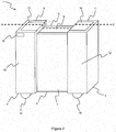
Figure 1 shows schematically a perspective view of a first example of apparatus for storing food and drink, with a second compartment in a first position; -
Figure 2 shows schematically a perspective view of the apparatus shown inFigure 1 , with the second compartment in a second position; -
Figure 3 shows schematically a cross-section of the apparatus shown inFigure 2 , the cross-section taken across line "A-A" ofFigure 2 ; -
Figure 4 shows schematically a perspective view of a second example of apparatus for storing food and drink, with a second compartment in a first position; and -
Figure 5 shows schematically a perspective view of the apparatus shown inFigure 4 , with the second compartment in a second position. - Consumables, such as food and drink, may conveniently be stored in apparatus, such as furniture (e.g. cupboards, cabinets etc.) and domestic appliances such as refrigeration apparatus (e.g. refrigerator, freezer etc.). Such apparatus typically includes at least one closed compartment so as to limit the effect of heat and/or light on the food and drink, which may degrade the quality of the food and drink. Some domestic appliances such as refrigeration apparatus is used to reduce the temperature of food and drink to keep it fresher for longer. The closed compartment in domestic and industrial refrigerators and freezers is thermally isolated from the outside environment and the refrigerator/freezer includes a heat pump that transfers heat from the inside of the apparatus to the outside environment so that the temperature of the inside of the apparatus is reduced. This lower temperature decreases the rate of reproduction of bacteria, which lowers the rate of spoilage of food and drink.
- The thermally isolated compartment of a refrigerator/freezer has a fixed volume. Consequently, only a certain amount of food and drink can be stored therein before the compartment becomes full. This problem can be addressed by using a refrigerator or freezer with a very large compartment. However, using a very large compartment is only cost effective when a very large amount of food and drink is stored in the refrigerator/freezer because otherwise the refrigerator/freezer is wasting energy by cooling a large volume of empty space.
- Referring now to
Figures 1 ,2 and3 , there is shown schematically an example ofapparatus 1 for storing food and drink. In this example, theapparatus 1 is a domestic freezer. In other examples, theapparatus 1 may be, for example, another refrigeration apparatus, such as an industrial freezer, a domestic refrigerator or an industrial refrigerator. - The
apparatus 1 has afirst compartment 2 which is nestable within asecond compartment 3. Eachcompartment first compartment 2 is a single compartment and thesecond compartment 3 is divided into afirst sub-compartment 4 and asecond sub-compartment 5. Thefirst sub-compartment 4 is completely separated from thesecond sub-compartment 5. Thefirst compartment 2 is completely separate from the first andsecond sub-compartments first compartment 2,first sub-compartment 4 and second sub-compartment 5 (or the second compartment 3) may be fluidly connected to one another so that the interior of each compartment or sub-compartment can be accessed through the interior of another compartment or sub-compartment. - The
first compartment 2 has a cuboid shape. In other examples, thefirst compartment 2 may be another shape so long as the shape is suitable for storing a quantity of food and drink. Thefirst compartment 2 has a number of faces including afirst face 6 and asecond face 7. In normal use, thefirst face 6 is the top face of thefirst compartment 2 and thesecond face 7 is the front face of thefirst compartment 2. Adoor 8 is provided for allowing a user access into the internal volume of thefirst compartment 2. Thedoor 8 is attached to thefirst compartment 2 by use of a hinge, and includes a handle. In this example, thedoor 8 is attached to thefirst face 6 of thefirst compartment 2. In other examples, thedoor 8 may be provided at any face of thefirst compartment 2 that allows for a user to access and reach into the internal volume of thefirst compartment 2, such as thesecond face 7. The walls and thedoor 8 of thefirst compartment 2 include thermal insulation to thermally isolate thefirst compartment 2 from the environment. This allows for the temperature inside thefirst compartment 2 to be maintained and limits the effect of the external temperature on its internal temperature. Thefirst compartment 2 in this example is supported off of the ground by thesecond compartment 3. - In this example, the
second compartment 3 is divided into afirst sub-compartment 4 and asecond sub-compartment 5. In other examples, thesecond compartment 3 may be a single compartment. Eachsub-compartment sub-compartments first sub-compartment 4 and thesecond sub-compartment 5 may another shape so long as the shape is suitable for storing a quantity of food and drink. Thesub-compartments - The
first sub-compartment 4 has a number of faces including afirst face 9 and asecond face 10. Thesecond sub-compartment 5 has a number of faces including afirst face 11 and asecond face 12. In normal use, the first faces 9, 11 are the top faces of thefirst sub-compartment 4 and thesecond sub-compartment 5, respectively. In normal use, the second faces 10, 12 are the front faces of thefirst sub-compartment 4 and thesecond sub-compartment 5, respectively. Adoor 13 is provided for allowing a user access into the internal volume of thefirst sub-compartment 4. Thedoor 13 is attached to thefirst sub-compartment 4 by use of a hinge, and includes a handle. In this example, thedoor 13 is attached to thefirst face 9 of thefirst sub-compartment 4. Adoor 14 is provided for allowing a user access into the internal volume of thesecond sub-compartment 5. Thedoor 14 is attached to thesecond sub-compartment 5 by use of a hinge, and includes a handle. In this example, thedoor 14 is attached to thefirst face 11 of thesecond sub-compartment 5. In other examples, thedoors sub-compartments particular sub-compartment second face doors sub-compartments sub-compartments sub-compartments - The
first sub-compartment 4 includes afirst wheel 15 which elevates it off of the ground. Similarly, thesecond sub-compartment 5 includes asecond wheel 16 which elevates it off of the ground. Thewheels apparatus 1 so as to assist in allowing thesecond compartment 3 to move between a first, closed position (as shown inFigure 1 ) and a second, open position (as shown inFigure 2 ). These positions and the significance thereof will be described in further detail below. In this example, thewheels respective sub-compartment apparatus 1. - The
apparatus 1 also includes one or more driving elements constructed and arranged to drive thesecond compartment 3 between the first (or closed) position (as shown inFigure 1 ) and the second (or open) position (as shown inFigure 2 ). Each driving element may be any suitable mechanism that can drive thesecond compartment 3 between the first position and the second position. As shown inFigure 3 , each driving element in this example is a double-acting hydraulic orpneumatic actuator 17 that can extend and contract to provide unidirectional force. Afirst end 18 of each actuator 17 is attached to thefirst compartment 2 and asecond end 19 of each actuator 17 is attached to thesecond compartment 3. In this example, the one or more driving elements are therefore connected between thefirst compartment 2 and thefirst sub-compartment 4, and thefirst compartment 2 and thesecond sub-compartment 5. Specifically, thefirst end 18 of each actuator 17 is attached to thefirst compartment 2 and thesecond end 19 of each actuator is attached to either thefirst sub-compartment 4 or thesecond sub-compartment 5. It should be noted that the driving elements/actuators 17 can also drive thesecond compartment 3 to, and maintain it at, any position between the first and second positions. In this example, a plurality of driving elements are provided. Specifically, theapparatus 1 includes eight driving elements, which are hydraulic orpneumatic actuators 17. A hydraulic or pneumatic drive system is also provided within theapparatus 1. The drive system includes components that are known to a person skilled in the art that allow it to function and supply hydraulic or pneumatic fluid to extend and contract theactuators 17, such as a generator or hydraulic or pneumatic pump, which is driven by a motor or an engine, valves, filters and piping, etc. In other examples, each drivingelement 17 may be an actuator powered by an electric motor. - When the
second compartment 3 is in the first position (as shown inFigure 1 ), thefirst compartment 2 and thesecond compartment 3 are adjacent or near to one another. In particular, in this example, when thesecond compartment 3 is in the first position, thesecond compartment 3 is entirely contained or nested within thefirst compartment 2. At this first position, therefore, in this example the usable internal volume of theapparatus 1 is minimised and corresponds to the internal volume of thesecond compartment 3. When thesecond compartment 3 is in the second position (as shown inFigure 2 ), thefirst compartment 2 and thesecond compartment 3 are spaced away from one another such that the volume (e.g. the internal volume) defined by theapparatus 1 when thesecond compartment 3 is in the second position is larger than the volume defined by theapparatus 1 when thesecond compartment 3 is in the first position. At this second position, therefore, in this example the usable internal volume of theapparatus 1 is maximised and corresponds to the total internal volume of thefirst compartment 3 and thesecond compartment 3. - The
apparatus 1 includes aswitch 18. Theswitch 18 is positioned at a location where it can be easily accessed and operated by a user. In this example, theswitch 18 is provided on thesecond face 10 of thefirst sub-compartment 13. Theswitch 18 controls the operation of the motor that powers the pump of the hydraulic or pneumatic drive system, which supplies and purges fluid to and from theactuators 17, thus causing theactuators 17 to extend or contract. - Given that the
apparatus 1 in the example shown inFigures 1 ,2 and3 is a freezer, theapparatus 1 also includes the necessary equipment to allow the internal volume of thefirst compartment 2 and thesecond compartment 3 to be cooled, as would be understood by a person skilled in the art. Theapparatus 1 may include a heat pump that transfers heat from the internal volume of theapparatus 1 to the surrounding environment. In particular, theapparatus 1 may include a compressor, a condenser, an expander and an evaporator, together with valves, piping, refrigerant, a power source etc. - An example of use of the
apparatus 1 will now be described with particular reference toFigures 1 and2 . - In
Figure 1 thesecond compartment 3 of theapparatus 1 is in the first position. The first position defines a certain volume of theapparatus 1. A user can therefore store a certain quantity of food and drink in theapparatus 1. The user can access the interior of theapparatus 1 so that they can put the food and drink into theapparatus 1 by lifting either of thedoors apparatus 1 in this example is a freezer, the temperature of any food and drink stored in theapparatus 1 will decreased until it becomes frozen. - If the user requires a larger volume of the
apparatus 1 in which to store food and drink (i.e. if the user has a higher quantity of food and drink to be stored than is permitted by the volume defined by theapparatus 1 when thesecond compartment 3 is in the first position), the user presses theswitch 18. Pressing theswitch 18 activates the motor that powers the pump of the hydraulic or pneumatic drive system. The pump thus supplies fluid to theactuators 17, which drives each of them to extend from their contracted position to their extended position. This drives thesecond compartment 3 from the first position (as shown inFigure 1 ) towards and ultimately to the second position (as shown inFigures 2 and3 ). Thewheels apparatus 1 facilitate this movement by reducing the friction between theapparatus 1 and the ground upon which it is positioned. - In
Figures 2 and3 , thesecond compartment 3 is in the second position where each of thesub-compartments first compartment 2. Consequently, the volume defined by theapparatus 1 is now increased because it is the equivalent of the volume of thefirst compartment 2 plus the volume of the first andsecond sub-compartments second compartment 3 is in this second position, a user can store more food and drink in the interior of theapparatus 1 than they can when thesecond compartment 3 is in the first position. - Due to using
actuators 17 to drive thesecond compartment 3 between the first and second positions, it is possible for a user to stop thesecond compartment 3 in an intermediary position between the first and second positions. This allows for use of an intermediary volume defined by theapparatus 1, between the volumes defined by theapparatus 1 when thesecond compartment 3 is in the first and second positions. - If, when the
second compartment 3 is in the second position, the user decides that the enlarged volume defined by theapparatus 1 is unnecessary because they only need to store a low quantity or volume of food and drink in theapparatus 1, the user can decrease the volume of theapparatus 1 by moving thesecond compartment 3 back to the first position. To this end, the user presses theswitch 18, which activates the motor powering pump. The pump then supplies fluid to the plurality ofactuators 17, which drives each of them to contract towards their contracted position. This drives thesecond compartment 3 from second position (as shown inFigures 2 and3 ) towards and ultimately to the first position (as shown inFigure 1 ). The smaller volume defined by theapparatus 1 when the second compartment is in the first position is more energy efficient when a low quantity/volume of food and drink is being stored in theapparatus 1 because a large volume of empty space is not required to be cooled. - In the example shown in
Figures 1 ,2 and3 , thesecond compartment 3 is divided down its middle into afirst sub-compartment 3 and asecond sub-compartment 4. To move thesecond compartment 3 in to the second position, the driving elements, which in this example are a plurality ofactuators 17, drive thefirst sub-compartment 3 andsecond sub-compartment 4 laterally away from the first compartment 2 (and from one another in this example). Other arrangements are possible, in which thesecond compartment 3 is driven away from thefirst compartment 2 such that volume defined by theapparatus 1 when thesecond compartment 3 is in the second position is larger than the volume defined by theapparatus 1 when thesecond compartment 3 is in the first position. -
Figures 4 and5 show a second example ofapparatus 201 for storing consumables. Theapparatus 201 of the second example has afirst compartment 202 which is nestable within asecond compartment 203. Each compartment is suitable for storing a certain quantity of consumables, such as food and drink. Theapparatus 201 shown inFigures 4 and5 has a substantially similar structure and substantially similar features to theapparatus 1 shown inFigures 1 ,2 and3 . - However, whilst the
second compartment 3 in the example shown inFigures 1 ,2 and3 is divided into two sub-compartments, thesecond compartment 203 in the example shown inFigures 4 and5 is a single compartment. This is a first difference between theapparatus 1 ofFigures 1 to 3 and theapparatus 201 ofFigures 4 and5 . - A second difference is that the
second compartment 203 is positioned so that it sits over and envelops thefirst compartment 203 when it is in the first position (as shown inFigure 4 ). - A third difference is that the plurality of actuators (not shown in
Figures 4 and5 ) are mounted in a vertically oriented position so that they can drive thesecond compartment 203 vertically to the second position (as shown inFigure 5 ) by lifting it upwards and away from thefirst compartment 202. In contrast, theapparatus 1 shown inFigures 1 ,2 and3 , the actuators are mounted in a horizontally oriented position for driving the first andsecond sub-compartments - As with the
apparatus 1 ofFigures 1 to 3 , the volume defined by theapparatus 201 is adjustable by operating theswitch 218. Theswitch 218 controls a motor which powers a pump. The pump supplies fluid to the plurality of actuators (not shown), which are consequently driven to move between their extended position and contracted positions. Driving the actuators from their contracted position to their extended position drives thesecond compartment 203 from the first position (as shown inFigure 4 ) towards and ultimately to the second position (as shown inFigure 5 ). Driving the actuators from their extended position to their contracted position drives thesecond compartment 203 from the second position (as shown inFigure 5 ) towards and ultimately to the first position (as shown inFigure 4 ). - An advantage of the above arrangements is that the interior volume defined by the
apparatus apparatus apparatus apparatus - The examples described herein are to be understood as illustrative examples of embodiments of the invention. Further embodiments and examples are envisaged. Any feature described in relation to any one example or embodiment may be used alone or in combination with other features. In addition, any feature described in relation to any one example or embodiment may also be used in combination with one or more features of any other of the examples or embodiments, or any combination of any other of the examples or embodiments. Furthermore, equivalents and modifications not described herein may also be employed within the scope of the invention, which is defined in the claims.
Claims (11)
- Apparatus for storing consumables, the apparatus comprising:a first compartment and a second compartment, the first compartment being nestable within the second compartment; andone or more driving elements attached between the first and second compartments and being constructed and arranged to drive the second compartment between a first position and a second position relative to the first compartment,wherein, when in the second position, the first and second compartments are spaced away from one another such that the volume defined by the apparatus when the second compartment is in the second position is larger than the volume defined by the apparatus when the second compartment is in the first position.
- Apparatus according to claim 1, wherein the apparatus is a domestic appliance.
- Apparatus according to claim 1 or claim 2, wherein the apparatus is refrigeration apparatus.
- Apparatus according to any preceding claim, wherein the second compartment is divided into at least two sub-compartments.
- Apparatus according to any preceding claim, wherein the one or more driving elements comprise actuators.
- Apparatus according to claim 5, wherein the actuators are hydraulic or pneumatic actuators.
- Apparatus according to claim 6, wherein a first end of each actuator is attached to the first compartment and a second end of each actuator is attached to the second compartment.
- Apparatus according to any preceding claim, wherein the one or more driving elements are attached between the first and second compartments such that the second compartment or at least one sub-compartment of the second compartment is driven horizontally relative to the first compartment into the second position.
- Apparatus according to any one of claims 1 to 7, wherein the one or more driving elements are attached between the first and second compartments such that the second compartment or at least one sub-compartment of the second compartment is driven vertically relative to the first compartment into the second position.
- Apparatus according to any preceding claim, comprising one or more wheels mounted to the apparatus for facilitating movement of the second compartment into the second position.
- Apparatus according to any preceding claim, wherein when the second compartment is in the first position, the second compartment fully envelops the first compartment.
Priority Applications (2)
| Application Number | Priority Date | Filing Date | Title |
|---|---|---|---|
| EP17182449.3A EP3431907A1 (en) | 2017-07-20 | 2017-07-20 | Apparatus for storing consumables |
| TR2017/19027A TR201719027A2 (en) | 2017-07-20 | 2017-11-28 | APPARATUS FOR STORAGE OF CONSUMABLE MATERIALS |
Applications Claiming Priority (1)
| Application Number | Priority Date | Filing Date | Title |
|---|---|---|---|
| EP17182449.3A EP3431907A1 (en) | 2017-07-20 | 2017-07-20 | Apparatus for storing consumables |
Publications (1)
| Publication Number | Publication Date |
|---|---|
| EP3431907A1 true EP3431907A1 (en) | 2019-01-23 |
Family
ID=59383517
Family Applications (1)
| Application Number | Title | Priority Date | Filing Date |
|---|---|---|---|
| EP17182449.3A Withdrawn EP3431907A1 (en) | 2017-07-20 | 2017-07-20 | Apparatus for storing consumables |
Country Status (2)
| Country | Link |
|---|---|
| EP (1) | EP3431907A1 (en) |
| TR (1) | TR201719027A2 (en) |
Cited By (1)
| Publication number | Priority date | Publication date | Assignee | Title |
|---|---|---|---|---|
| EP3816372A1 (en) * | 2019-10-28 | 2021-05-05 | Dzemil Djedovic | Mobile device for the temporary cooling of goods |
Citations (9)
| Publication number | Priority date | Publication date | Assignee | Title |
|---|---|---|---|---|
| JPH02133782A (en) * | 1988-11-14 | 1990-05-22 | Sanden Corp | Home delivery item receiving box with cooling device |
| US20050268622A1 (en) * | 2004-06-08 | 2005-12-08 | Vector Products, Inc. | Expandable cooler |
| WO2006067505A1 (en) * | 2004-12-23 | 2006-06-29 | Chris Piponides | Extendible refrigerator/appliance |
| DE202006005577U1 (en) * | 2006-04-04 | 2007-08-16 | Grass Gmbh | Device for moving a first furniture part relative to a second furniture part |
| EP2402688A1 (en) * | 2010-06-29 | 2012-01-04 | Indesit Company S.p.A. | Expandable refrigerating appliance |
| DE102012202940A1 (en) * | 2012-02-27 | 2013-08-29 | BSH Bosch und Siemens Hausgeräte GmbH | Domestic refrigerating appliance for use in kitchen, has thermally insulating end, storage chamber, door leaf formed for opening and closing storage chamber, and refrigerating device formed to cool storage chamber |
| CN103776225A (en) * | 2014-01-24 | 2014-05-07 | 张卫 | Telescopic refrigerator |
| CN104197600A (en) * | 2014-08-26 | 2014-12-10 | 浙江大学 | Telescopic refrigerator |
| DE102015102139A1 (en) * | 2015-02-13 | 2016-08-18 | Petratschek GmbH | Caddy-storage cabinet |
-
2017
- 2017-07-20 EP EP17182449.3A patent/EP3431907A1/en not_active Withdrawn
- 2017-11-28 TR TR2017/19027A patent/TR201719027A2/en unknown
Patent Citations (9)
| Publication number | Priority date | Publication date | Assignee | Title |
|---|---|---|---|---|
| JPH02133782A (en) * | 1988-11-14 | 1990-05-22 | Sanden Corp | Home delivery item receiving box with cooling device |
| US20050268622A1 (en) * | 2004-06-08 | 2005-12-08 | Vector Products, Inc. | Expandable cooler |
| WO2006067505A1 (en) * | 2004-12-23 | 2006-06-29 | Chris Piponides | Extendible refrigerator/appliance |
| DE202006005577U1 (en) * | 2006-04-04 | 2007-08-16 | Grass Gmbh | Device for moving a first furniture part relative to a second furniture part |
| EP2402688A1 (en) * | 2010-06-29 | 2012-01-04 | Indesit Company S.p.A. | Expandable refrigerating appliance |
| DE102012202940A1 (en) * | 2012-02-27 | 2013-08-29 | BSH Bosch und Siemens Hausgeräte GmbH | Domestic refrigerating appliance for use in kitchen, has thermally insulating end, storage chamber, door leaf formed for opening and closing storage chamber, and refrigerating device formed to cool storage chamber |
| CN103776225A (en) * | 2014-01-24 | 2014-05-07 | 张卫 | Telescopic refrigerator |
| CN104197600A (en) * | 2014-08-26 | 2014-12-10 | 浙江大学 | Telescopic refrigerator |
| DE102015102139A1 (en) * | 2015-02-13 | 2016-08-18 | Petratschek GmbH | Caddy-storage cabinet |
Cited By (1)
| Publication number | Priority date | Publication date | Assignee | Title |
|---|---|---|---|---|
| EP3816372A1 (en) * | 2019-10-28 | 2021-05-05 | Dzemil Djedovic | Mobile device for the temporary cooling of goods |
Also Published As
| Publication number | Publication date |
|---|---|
| TR201719027A2 (en) | 2019-02-21 |
Similar Documents
| Publication | Publication Date | Title |
|---|---|---|
| EP3023717B1 (en) | Refrigerator | |
| EP2278239B1 (en) | High efficiency refrigerator | |
| US20110072849A1 (en) | Combined refrigerant compressor and secondary liquid coolant pump | |
| US20150330678A1 (en) | Refrigerator | |
| KR102261114B1 (en) | Refrigerator | |
| EP2772707B1 (en) | Multiple evaporator control using pwm valve/compressor | |
| US20160282032A1 (en) | Multiple evaporator control using pwm valve/compressor | |
| KR102679833B1 (en) | Container and Refrigerator including the same | |
| US10591200B2 (en) | Low energy refrigerator heat source | |
| CN116472407A (en) | Variable capacity drive circuit for linear compressors in refrigeration appliances | |
| KR102418143B1 (en) | Refrigerator and Controlling method for the same | |
| KR101586537B1 (en) | Shelf including a cold storage material therein, and refrigerator having the same | |
| JP2006242463A (en) | refrigerator | |
| JP4189428B1 (en) | Storage | |
| KR102293702B1 (en) | Easy-to-use refrigerator of drawer type | |
| KR20130094042A (en) | Refrigerator having drawing out type sliding door | |
| US9347694B2 (en) | Dual suction compressor with rapid suction port switching mechanism for matching appliance compartment thermal loads with cooling capacity | |
| KR101369453B1 (en) | Refrigerator and method for control cool air of refrigerator | |
| US20160370073A1 (en) | Ice selector apparatus and method | |
| JP2005098605A (en) | refrigerator | |
| KR200221428Y1 (en) | Multipurpose Refrigerator | |
| KR101150946B1 (en) | refrigerator | |
| KR200498133Y1 (en) | A spice jar cabinet equipped with a refrigerator | |
| RU2402727C1 (en) | Domestic refrigerator | |
| KR100434395B1 (en) | Side-by-side type refrigerator having apparatus for fixation of 2nd cold storage |
Legal Events
| Date | Code | Title | Description |
|---|---|---|---|
| PUAI | Public reference made under article 153(3) epc to a published international application that has entered the european phase |
Free format text: ORIGINAL CODE: 0009012 |
|
| STAA | Information on the status of an ep patent application or granted ep patent |
Free format text: STATUS: THE APPLICATION HAS BEEN PUBLISHED |
|
| AK | Designated contracting states |
Kind code of ref document: A1 Designated state(s): AL AT BE BG CH CY CZ DE DK EE ES FI FR GB GR HR HU IE IS IT LI LT LU LV MC MK MT NL NO PL PT RO RS SE SI SK SM TR |
|
| AX | Request for extension of the european patent |
Extension state: BA ME |
|
| STAA | Information on the status of an ep patent application or granted ep patent |
Free format text: STATUS: THE APPLICATION IS DEEMED TO BE WITHDRAWN |
|
| 18D | Application deemed to be withdrawn |
Effective date: 20190724 |