EP3431905A1 - An apparatus and method for detecting freezing of a substance - Google Patents
An apparatus and method for detecting freezing of a substance Download PDFInfo
- Publication number
- EP3431905A1 EP3431905A1 EP17182095.4A EP17182095A EP3431905A1 EP 3431905 A1 EP3431905 A1 EP 3431905A1 EP 17182095 A EP17182095 A EP 17182095A EP 3431905 A1 EP3431905 A1 EP 3431905A1
- Authority
- EP
- European Patent Office
- Prior art keywords
- container
- substance
- solid
- contact
- brought
- Prior art date
- Legal status (The legal status is an assumption and is not a legal conclusion. Google has not performed a legal analysis and makes no representation as to the accuracy of the status listed.)
- Granted
Links
Images

Classifications
-
- F—MECHANICAL ENGINEERING; LIGHTING; HEATING; WEAPONS; BLASTING
- F25—REFRIGERATION OR COOLING; COMBINED HEATING AND REFRIGERATION SYSTEMS; HEAT PUMP SYSTEMS; MANUFACTURE OR STORAGE OF ICE; LIQUEFACTION SOLIDIFICATION OF GASES
- F25D—REFRIGERATORS; COLD ROOMS; ICE-BOXES; COOLING OR FREEZING APPARATUS NOT OTHERWISE PROVIDED FOR
- F25D21/00—Defrosting; Preventing frosting; Removing condensed or defrost water
- F25D21/02—Detecting the presence of frost or condensate
-
- F—MECHANICAL ENGINEERING; LIGHTING; HEATING; WEAPONS; BLASTING
- F25—REFRIGERATION OR COOLING; COMBINED HEATING AND REFRIGERATION SYSTEMS; HEAT PUMP SYSTEMS; MANUFACTURE OR STORAGE OF ICE; LIQUEFACTION SOLIDIFICATION OF GASES
- F25D—REFRIGERATORS; COLD ROOMS; ICE-BOXES; COOLING OR FREEZING APPARATUS NOT OTHERWISE PROVIDED FOR
- F25D2700/00—Means for sensing or measuring; Sensors therefor
- F25D2700/12—Sensors measuring the inside temperature
Definitions
- the present disclosure relates to an apparatus and method for detecting freezing of a substance.
- So-called frost-free refrigeration apparatus such as freezers and refrigerators and the like, employ various complex methods for preventing a build up of ice.
- One example of such a method is periodically heating the freezer or refrigerator to melt any ice that may have formed inside. This process can be wasteful and inefficient.
- an apparatus for detecting freezing of a substance comprising:
- the first member is rotatable such that rotation of the first member brings the container of the first member into contact with the second member.
- the apparatus comprises an electric motor for driving the first member to bring the container of the first member into contact with the second member.
- the apparatus comprises a current monitor for detecting a surge in the motor drive current at the time that the container is brought into contact with the second member when the substance in the container is solid.
- the second member is arranged to be driven to move when the container is brought into contact with the second member when the substance in the container is solid, the apparatus comprising a generator which is drivable by the second member and which produces a current when driven by the second member.
- the second member comprises at least one container, the container having flexible walls and containing a substance which has a freezing temperature below which the substance is solid and above which the substance is fluid.
- the first member comprises plural containers, each container having flexible walls and containing a substance which has a freezing temperature below which the substance is solid and above which the substance is fluid.
- the substance is water which in its fluid state is water or steam and in its solid state it is ice.
- refrigeration apparatus comprising apparatus as described above.
- the refrigeration apparatus may be for example a refrigerator or a freezer.
- a method for detecting freezing of a substance comprising:
- the method comprises rotating the first member such that the rotation of the first member brings the container of the first member into contact with the second member.
- the method comprises an electric motor which drives the first member to move to bring the container of the first member into contact with the second member.
- the method comprises an indication received by a current monitor, wherein the indication is a surge in the motor drive current at the time that the container is brought into contact with the second member when the substance in the container is solid.
- the second member is driven to move when the container is brought into contact with the second member when the substance in the container is solid, and wherein the second member is able to drive a generator, the generator being arranged to produce a current when driven by the second member.
- the second member comprises at least one container, the container having flexible walls and containing a substance which has a freezing temperature below which the substance is solid and above which the substance is fluid.
- refrigeration apparatus such as for example frost-free freezers and refrigerators and the like, prevent a build-up of ice, particularly on for example the heat exchanger, using relatively complex or inefficient methods.
- One such method is periodically heating a heater that is located on or near the heat exchanger to melt any ice that may have formed. Often these methods are wasteful, particularly if heaters are used excessively, and inefficient. These methods have no regard for whether ice has actually formed, and simply periodically heat the heat exchanger regardless.
- an apparatus is arranged to detect the freezing of a substance, which may be for example water/ice.
- the apparatus has a first member comprising a container.
- the container has flexible walls.
- the container contains a substance which has a freezing temperature below which the substance is solid, and above which the substance is a fluid.
- the apparatus also has a second member.
- the first member and second member are arranged such that when the substance in the container of the first member is solid at a time that the container makes contact with the second member, an engagement between the first and second members is detected.
- Such apparatus may be used in a refrigeration apparatus, such as a refrigerator or a freezer or the like.
- Such apparatus may also be used in other applications where it may be useful to determine or detect that a substance has solidified.
- Figure 1 shows a first example of an apparatus 100 for detecting that a substance has solidified.
- a first member 102 has one or more containers 104 attached to it or integrally formed with it.
- the or each container 102 contains a substance for which it is desired to detect that it has frozen.
- the or each container 102 has flexible walls.
- the or each container 102 may be in the form of a balloon, and may be made of for example a synthetic or natural rubber or other elastomeric or plastics material.
- the first member 102 is movable to bring the one or more containers 104 into contact with a second member 106.
- the first member 102 may be rotatable to bring the containers 104 in contact with the second member 106.
- the first member 106 is a wheel.
- other shapes may be used.
- the first member 102 may be a rod, an example of which will be discussed further below.
- the first member 102 may be driven to move by an electric motor 108.
- the second member 106 is static.
- the second member 106 may be for example a wall or the like against which the container 104 can strike.
- the second member 106 may have a protrusion 110 against which the container 104 can strike.
- the first member 102 and the second member 106 are arranged such that when the substance in a container 104 of the first member 102 is solid. i.e. has frozen, the contact between the container 104 and the second member 106 can be detected, whereas when the substance in a container 104 of the first member 102 is not solid, any contact between the container 104 and the second member 106 is not detected.
- This can be done in a number of ways. In one example, a sharp increase in the current that is driving the motor 108 may be observed when movement of the motor 108 is inhibited, i.e. when a container 104 containing the substance in solid form strikes the second member 106.
- the first member may be in the shape or a rod, which can be brought into engagement with a second member, such as the second member 106 described above.
- the rod may carry at least one container, such as a container 104 described above, wherein the container has flexible walls and contains a substance.
- the rod may be arranged to move in a rotating or reciprocating or translational movement so as to bring the container(s) into contact with a static second member.
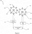
- FIG. 2 A second example of apparatus 200 for detecting freezing of a substance is shown in Figure 2 .
- a first member 202 similarly to the first example, a first member 202 has one or more containers 204 attached to it or integrally formed with it.
- the or each container 204 contains a substance for which it is desired to detect that it has frozen.
- the or each container 204 has flexible walls.
- the or each container 204 may be in the form of a balloon, and may be made of for example a synthetic or natural rubber or other elastomeric or plastics material.
- the first member 202 is movable to bring the one or more containers 204 into contact with a second member 206, in particular in contact with the containers 204 of the second member 206.
- the first member 206 is a wheel.
- the first member 202 may be driven to move by an electric motor 208.
- a first member is connected to a motor 208.
- the second member 206 is also rotatable and is in the form of a wheel. However, in other examples, other shapes may be used.
- the second member 206 has the one or more containers 204 attached to it or integrally formed with it.
- the containers 204 have flexible walls.
- the containers 204 of the second member 206 contain a substance which has a freezing temperature below which the substance is solid, and above which the substance is a fluid.
- the first member 202 and the second member 206 are arranged such that when a substance in a container 204 of the first member 202 is solid, the contact between the container(s) 204 of the first member 202 and the container(s) 204 of the second member 206 can be detected.
- the second member 206 is connected to a generator 212.
- the first member 202 is driven to rotate by the motor 208.
- a power supply unit 210 drives the motor 208.
- the containers 204 of the first member 202 are not stiff or rigid enough to connect with the containers 204 of the second member 206 in a manner that causes the second member 206 to move.
- the first member 202 causes the second member 206 to move.
- the movement of the second member 206 is a rotational movement.
- the movement of the second member may drive a generator 212.
- the output of the generator is connected to an ADC (analogue to digital conversion) unit 214.
- An output of the ADC unit 204 is passed to a microcontroller unit 216.
- the microcontroller unit 216 receives an indication that the second member 206 has driven the generator 212 to move.
- the microcontroller unit 216 in this example is connected to the power supply unit 210 which drives the motor 208 for the first member 202.
- the frictional force associated with movement of the generator 212 may be relatively high. This may help to ensure that movement of the second member 208 is minimized or prevented altogether when the substance in the containers 204 of the first member 202 is a fluid. The frictional force associated with movement of the motor 208 may be low.
- the microcontroller unit 216 may be arranged to control a component to heat the environment in which the first member and second member reside. The microcontroller unit may be arranged to continue to provide this control signal until the generator stops generating a current. Additionally or alternatively, the heating component may be arranged to heat the environment until the substance in the container returns to a fluid state. Additionally or alternatively, the heating component may be arranged to heat the environment up to a maximum period of time. Additionally or alternatively the heating component may be arrange to heat the environment for a fixed period of time. In the specific example here, the microcontroller unit 216 may trigger an environmental change to cause the substance in the containers 206 to return to a fluid state.
- the apparatus may be used in a refrigerator or freezer.
- the apparatus may be used to detect a build up of ice, especially in heat exchangers.
- the substance in the container(s) will be water or steam in the fluid state and ice when in the solid state.
- the apparatus 100, 200 may trigger heating of one or more components of the refrigerator or freezer, or the region near the one or more components of the refrigerator or freezer, so as to melt any ice that has built up on the one or more components. This includes particularly heating the heat exchanger or the region near the heat exchanger of the refrigerator or freezer so as to melt any ice that has built up on the heat exchanger.
Landscapes
- Engineering & Computer Science (AREA)
- Chemical & Material Sciences (AREA)
- Combustion & Propulsion (AREA)
- Physics & Mathematics (AREA)
- Mechanical Engineering (AREA)
- Thermal Sciences (AREA)
- General Engineering & Computer Science (AREA)
- Production, Working, Storing, Or Distribution Of Ice (AREA)
- Investigating Or Analyzing Materials Using Thermal Means (AREA)
Description
- The present disclosure relates to an apparatus and method for detecting freezing of a substance.
- So-called frost-free refrigeration apparatus, such as freezers and refrigerators and the like, employ various complex methods for preventing a build up of ice. One example of such a method is periodically heating the freezer or refrigerator to melt any ice that may have formed inside. This process can be wasteful and inefficient.
- According to a first aspect disclosed herein, there is provided an apparatus for detecting freezing of a substance, the apparatus comprising:
- a first member comprising at least one container, the container having flexible walls and containing a substance which has a freezing temperature below which the substance is solid and above which the substance is fluid; and
- a second member;
- the first and second members being arranged such that the container of the first member can be brought into contact with the second member;
- the arrangement being such that engagement between the first and second members is detected when the substance in the container is solid at the time that the container of the first member is brought into contact with the second member.
- In an example, the first member is rotatable such that rotation of the first member brings the container of the first member into contact with the second member.
- In an example, the apparatus comprises an electric motor for driving the first member to bring the container of the first member into contact with the second member.
- In an example, the apparatus comprises a current monitor for detecting a surge in the motor drive current at the time that the container is brought into contact with the second member when the substance in the container is solid.
- In an example, the second member is arranged to be driven to move when the container is brought into contact with the second member when the substance in the container is solid, the apparatus comprising a generator which is drivable by the second member and which produces a current when driven by the second member.
- In an example, the second member comprises at least one container, the container having flexible walls and containing a substance which has a freezing temperature below which the substance is solid and above which the substance is fluid.
- In an example, the first member comprises plural containers, each container having flexible walls and containing a substance which has a freezing temperature below which the substance is solid and above which the substance is fluid.
- In an example, the substance is water which in its fluid state is water or steam and in its solid state it is ice.
- In an example, there is provided refrigeration apparatus comprising apparatus as described above. The refrigeration apparatus may be for example a refrigerator or a freezer.
- According to a second aspect disclosed herein, there is provided a method for detecting freezing of a substance, the method comprising:
- moving a first member, the first member comprising at least one container, the container having flexible walls and containing a substance which has a freezing temperature below which the substance is solid and above which the substance is fluid;
- bringing the container of the first member into contact with a second member; and
- receiving an indication that the substance in the container is solid at the time that the container of the first member is brought into contact with the second member.
- In an example, the method comprises rotating the first member such that the rotation of the first member brings the container of the first member into contact with the second member.
- In an example, the method comprises an electric motor which drives the first member to move to bring the container of the first member into contact with the second member.
- In an example, the method comprises an indication received by a current monitor, wherein the indication is a surge in the motor drive current at the time that the container is brought into contact with the second member when the substance in the container is solid.
- In an example, the second member is driven to move when the container is brought into contact with the second member when the substance in the container is solid, and wherein the second member is able to drive a generator, the generator being arranged to produce a current when driven by the second member.
- In an example, the second member comprises at least one container, the container having flexible walls and containing a substance which has a freezing temperature below which the substance is solid and above which the substance is fluid.
- To assist understanding of the present disclosure and to show how embodiments may be put into effect, reference is made by way of example to the accompanying drawings in which:
-
Figure 1 shows schematically a first example of apparatus for detecting freezing of a substance; and -
Figure 2 shows schematically a second example of apparatus for detecting freezing of a substance. - As mentioned previously, refrigeration apparatus, such as for example frost-free freezers and refrigerators and the like, prevent a build-up of ice, particularly on for example the heat exchanger, using relatively complex or inefficient methods. One such method is periodically heating a heater that is located on or near the heat exchanger to melt any ice that may have formed. Often these methods are wasteful, particularly if heaters are used excessively, and inefficient. These methods have no regard for whether ice has actually formed, and simply periodically heat the heat exchanger regardless.
- According to examples described herein, an apparatus is arranged to detect the freezing of a substance, which may be for example water/ice. The apparatus has a first member comprising a container. The container has flexible walls. The container contains a substance which has a freezing temperature below which the substance is solid, and above which the substance is a fluid. The apparatus also has a second member. The first member and second member are arranged such that when the substance in the container of the first member is solid at a time that the container makes contact with the second member, an engagement between the first and second members is detected. Such apparatus may be used in a refrigeration apparatus, such as a refrigerator or a freezer or the like. Such apparatus may also be used in other applications where it may be useful to determine or detect that a substance has solidified.
-
Figure 1 shows a first example of anapparatus 100 for detecting that a substance has solidified. Afirst member 102 has one ormore containers 104 attached to it or integrally formed with it. The or eachcontainer 102 contains a substance for which it is desired to detect that it has frozen. The or eachcontainer 102 has flexible walls. The or eachcontainer 102 may be in the form of a balloon, and may be made of for example a synthetic or natural rubber or other elastomeric or plastics material. - The
first member 102 is movable to bring the one ormore containers 104 into contact with asecond member 106. Thefirst member 102 may be rotatable to bring thecontainers 104 in contact with thesecond member 106. In the example shown, thefirst member 106 is a wheel. However, in other examples, other shapes may be used. For example, thefirst member 102 may be a rod, an example of which will be discussed further below. - The
first member 102 may be driven to move by anelectric motor 108. In this example, thesecond member 106 is static. Thesecond member 106 may be for example a wall or the like against which thecontainer 104 can strike. Thesecond member 106 may have aprotrusion 110 against which thecontainer 104 can strike. - The
first member 102 and thesecond member 106 are arranged such that when the substance in acontainer 104 of thefirst member 102 is solid. i.e. has frozen, the contact between thecontainer 104 and thesecond member 106 can be detected, whereas when the substance in acontainer 104 of thefirst member 102 is not solid, any contact between thecontainer 104 and thesecond member 106 is not detected. This can be done in a number of ways. In one example, a sharp increase in the current that is driving themotor 108 may be observed when movement of themotor 108 is inhibited, i.e. when acontainer 104 containing the substance in solid form strikes thesecond member 106. In particular, when acontainer 104 of thefirst member 102 is brought into contact with thesecond member 106 and the substance in thecontainer 104 is solid, the motion of thefirst member 102 is dampened or supressed. As is known per se, this has the effect of causing the drive current in themotor 108 to rise sharply, which can be detected by a current monitoring circuit. - In another example (not shown), the first member may be in the shape or a rod, which can be brought into engagement with a second member, such as the
second member 106 described above. The rod may carry at least one container, such as acontainer 104 described above, wherein the container has flexible walls and contains a substance. The rod may be arranged to move in a rotating or reciprocating or translational movement so as to bring the container(s) into contact with a static second member. - A second example of
apparatus 200 for detecting freezing of a substance is shown inFigure 2 . In this example, similarly to the first example, afirst member 202 has one ormore containers 204 attached to it or integrally formed with it. The or eachcontainer 204 contains a substance for which it is desired to detect that it has frozen. The or eachcontainer 204 has flexible walls. The or eachcontainer 204 may be in the form of a balloon, and may be made of for example a synthetic or natural rubber or other elastomeric or plastics material. Thefirst member 202 is movable to bring the one ormore containers 204 into contact with asecond member 206, in particular in contact with thecontainers 204 of thesecond member 206. In the example shown, thefirst member 206 is a wheel. Thefirst member 202 may be driven to move by anelectric motor 208. A first member is connected to amotor 208. - In this example, the
second member 206 is also rotatable and is in the form of a wheel. However, in other examples, other shapes may be used. Thesecond member 206 has the one ormore containers 204 attached to it or integrally formed with it. Thecontainers 204 have flexible walls. Thecontainers 204 of thesecond member 206 contain a substance which has a freezing temperature below which the substance is solid, and above which the substance is a fluid. - The
first member 202 and thesecond member 206 are arranged such that when a substance in acontainer 204 of thefirst member 202 is solid, the contact between the container(s) 204 of thefirst member 202 and the container(s) 204 of thesecond member 206 can be detected. To achieve this, in this example thesecond member 206 is connected to agenerator 212. - In the example shown in
Figure 2 , thefirst member 202 is driven to rotate by themotor 208. Apower supply unit 210 drives themotor 208. When the substance in thecontainers 204 is fluid, thecontainers 204 of thefirst member 202 are not stiff or rigid enough to connect with thecontainers 204 of thesecond member 206 in a manner that causes thesecond member 206 to move. When the substance in thecontainers 204 is solid, thefirst member 202 causes thesecond member 206 to move. - In this example, the movement of the
second member 206 is a rotational movement. The movement of the second member may drive agenerator 212. The output of the generator is connected to an ADC (analogue to digital conversion)unit 214. An output of theADC unit 204 is passed to amicrocontroller unit 216. In use, themicrocontroller unit 216 receives an indication that thesecond member 206 has driven thegenerator 212 to move. Themicrocontroller unit 216 in this example is connected to thepower supply unit 210 which drives themotor 208 for thefirst member 202. - Additionally, the frictional force associated with movement of the
generator 212 may be relatively high. This may help to ensure that movement of thesecond member 208 is minimized or prevented altogether when the substance in thecontainers 204 of thefirst member 202 is a fluid. The frictional force associated with movement of themotor 208 may be low. - In an example embodiment, the
microcontroller unit 216 may be arranged to control a component to heat the environment in which the first member and second member reside. The microcontroller unit may be arranged to continue to provide this control signal until the generator stops generating a current. Additionally or alternatively, the heating component may be arranged to heat the environment until the substance in the container returns to a fluid state. Additionally or alternatively, the heating component may be arranged to heat the environment up to a maximum period of time. Additionally or alternatively the heating component may be arrange to heat the environment for a fixed period of time. In the specific example here, themicrocontroller unit 216 may trigger an environmental change to cause the substance in thecontainers 206 to return to a fluid state. - In one specific application of the examples of the
apparatus apparatus - The examples described herein are to be understood as illustrative examples of embodiments of the invention. Further embodiments and examples are envisaged. Any feature described in relation to any one example or embodiment may be used alone or in combination with other features. In addition, any feature described in relation to any one example or embodiment may also be used in combination with one or more features of any other of the examples or embodiments, or any combination of any other of the examples or embodiments. Furthermore, equivalents and modifications not described herein may also be employed within the scope of the invention, which is defined in the claims.
Claims (15)
- An apparatus for detecting freezing of a substance, the apparatus comprising:a first member (102, 202) comprising at least one container (104, 204), the container (104, 204) having flexible walls and containing a substance which has a freezing temperature below which the substance is solid and above which the substance is fluid; anda second member (106, 206);the first and second members (104, 204, 106, 206) being arranged such that the container (104, 204) of the first member (102, 202) can be brought into contact with the second member (106, 206);the arrangement being such that engagement between the first (102, 202) and second members (106, 206) is detected when the substance in the container (104, 204) is solid at the time that the container (104, 204) of the first member (102, 202) is brought into contact with the second member (106, 206).
- An apparatus according to claim 1, wherein the first member (102, 202) is rotatable such that rotation of the first member (102, 202) brings the container (104, 204) of the first member (102, 202) into contact with the second member (106, 206).
- An apparatus according to claim 1 or claim 2, comprising an electric motor (108, 208) for driving the first member (102, 202) to bring the container (104, 204) of the first member (102, 202) into contact with the second member (106, 206).
- An apparatus according to claim 3, comprising a current monitor for detecting a surge in the motor (108, 208) drive current at the time that the container (104, 204) is brought into contact with the second member (106, 206) when the substance in the container (104, 204) is solid.
- An apparatus according to any of claims 1 to 4, wherein the second member (106, 206) is arranged to be driven to move when the container (104, 204) is brought into contact with the second member (106, 206) when the substance in the container (104, 204) is solid, the apparatus comprising a generator which is drivable by the second member (106, 206) and which produces a current when driven by the second member (106, 206).
- An apparatus according to any of claims 1 to 5, wherein the second member (106, 206) comprises at least one container (104, 204), the container (104, 204) having flexible walls and containing a substance which has a freezing temperature below which the substance is solid and above which the substance is fluid.
- An apparatus according to any of claims 1 to 6, wherein the first member (102, 202) comprises plural containers (104, 204), each container (104, 204) having flexible walls and containing a substance which has a freezing temperature below which the substance is solid and above which the substance is fluid.
- An apparatus according to any of claims 1 to 7, wherein the substance is water which in its fluid state is water or steam and in its solid state it is ice.
- A refrigeration apparatus comprising apparatus according to any of claims 1 to 8.
- A method for detecting freezing of a substance, the method comprising:moving a first member (102, 202), the first member (102, 202) comprising at least one container (104, 204), the container (104, 204) having flexible walls and containing a substance which has a freezing temperature below which the substance is solid and above which the substance is fluid;bringing the container (104, 204) of the first member (102, 202) into contact with a second member (106, 206); andreceiving an indication that the substance in the container (104, 204) is solid at the time that the container (104, 204) of the first member (102, 202) is brought into contact with the second member (106, 206).
- A method according to claim 10, comprising rotating the first member (102, 202) such that the rotation of the first member (102, 202) brings the container (104, 204) of the first member (102, 202) into contact with the second member (106, 206).
- A method according to claim 10 or claim 11, wherein an electric motor (108, 208) drives the first member (102, 202) to move to bring the container (104, 204) of the first member (102, 202) into contact with the second member (106, 206).
- A method according to claim 12, wherein the indication is received by a current monitor, wherein the indication is a surge in the motor (108, 208) drive current at the time that the container (104, 204) is brought into contact with the second member (106, 206) when the substance in the container (104, 204) is solid.
- A method according to any of claims 10 to 13, wherein the second member (106, 206) is driven to move when the container (104, 204) is brought into contact with the second member (106, 206) when the substance in the container (104, 204) is solid, and wherein the second member (106, 206) is able to drive a generator (212), the generator (212) being arranged to produce a current when driven by the second member (106, 206).
- A method according to any of claims 10 to 14, wherein the second member (106, 206) comprises at least one container (104, 204), the container (104, 204) having flexible walls and containing a substance which has a freezing temperature below which the substance is solid and above which the substance is fluid.
Priority Applications (2)
| Application Number | Priority Date | Filing Date | Title |
|---|---|---|---|
| EP17182095.4A EP3431905B1 (en) | 2017-07-19 | 2017-07-19 | An apparatus and method for detecting freezing of a substance |
| TR2017/11023A TR201711023A2 (en) | 2017-07-19 | 2017-07-27 | AN APPARATUS AND METHOD FOR DETECTING THE FREEZING OF A SUBSTANCE |
Applications Claiming Priority (1)
| Application Number | Priority Date | Filing Date | Title |
|---|---|---|---|
| EP17182095.4A EP3431905B1 (en) | 2017-07-19 | 2017-07-19 | An apparatus and method for detecting freezing of a substance |
Publications (2)
| Publication Number | Publication Date |
|---|---|
| EP3431905A1 true EP3431905A1 (en) | 2019-01-23 |
| EP3431905B1 EP3431905B1 (en) | 2020-03-25 |
Family
ID=59381175
Family Applications (1)
| Application Number | Title | Priority Date | Filing Date |
|---|---|---|---|
| EP17182095.4A Active EP3431905B1 (en) | 2017-07-19 | 2017-07-19 | An apparatus and method for detecting freezing of a substance |
Country Status (2)
| Country | Link |
|---|---|
| EP (1) | EP3431905B1 (en) |
| TR (1) | TR201711023A2 (en) |
Citations (2)
| Publication number | Priority date | Publication date | Assignee | Title |
|---|---|---|---|---|
| DE656208C (en) * | 1936-07-11 | 1938-02-01 | Elektrolux Akt Ges | Process for defrosting the ice on the evaporator or cooling element of a cooling device |
| US2622923A (en) * | 1949-03-11 | 1952-12-23 | Missouri Automatic Contr Corp | Ice bank controller |
-
2017
- 2017-07-19 EP EP17182095.4A patent/EP3431905B1/en active Active
- 2017-07-27 TR TR2017/11023A patent/TR201711023A2/en unknown
Patent Citations (2)
| Publication number | Priority date | Publication date | Assignee | Title |
|---|---|---|---|---|
| DE656208C (en) * | 1936-07-11 | 1938-02-01 | Elektrolux Akt Ges | Process for defrosting the ice on the evaporator or cooling element of a cooling device |
| US2622923A (en) * | 1949-03-11 | 1952-12-23 | Missouri Automatic Contr Corp | Ice bank controller |
Also Published As
| Publication number | Publication date |
|---|---|
| TR201711023A2 (en) | 2019-02-21 |
| EP3431905B1 (en) | 2020-03-25 |
Similar Documents
| Publication | Publication Date | Title |
|---|---|---|
| US2941379A (en) | Ice making apparatus | |
| EP2585772B1 (en) | Ice making method | |
| US20110314842A1 (en) | Method and apparatus for harvesting ice in an ice maker system | |
| AU2006338360B2 (en) | Apparatus for supercooling, and method of operating the same | |
| EP3431905B1 (en) | An apparatus and method for detecting freezing of a substance | |
| EP2685626B1 (en) | BLDC motor driving apparatus and refrigerator using the same | |
| CN107677039B (en) | Intelligent refrigerator | |
| US9890985B2 (en) | Refrigeration device comprising an ice maker with double stops | |
| US9752813B2 (en) | Refrigerator with thermoelectric device control process for an icemaker | |
| JP2000199672A (en) | refrigerator | |
| CN114094768B (en) | Intelligent industrial robot with efficient heat dissipation type motor | |
| US10006687B2 (en) | Control circuit | |
| CN115570231A (en) | Can regulate and control tin cream temperature machine that returns of temperature | |
| KR200389103Y1 (en) | ice-bar freezer | |
| EP2994706A1 (en) | A refrigerator comprising a storage compartment | |
| CN102313427A (en) | Refrigerator | |
| EP2770282B1 (en) | Method for controlling a refrigerating appliance | |
| CN119353827B (en) | Air source water heater suitable for aquaculture | |
| US10174981B2 (en) | Icemaker, process for controlling same and making ice | |
| KR20160042513A (en) | Rapidly with brine solution Freezer units | |
| EP3435011B1 (en) | An apparatus and method for detecting freezing of a substance | |
| CN205156459U (en) | Thalposis ice machine is taken off to ejector pin type side | |
| JP2015081727A (en) | Refrigerator | |
| KR20190037851A (en) | Ice maker, refrigerator including the same and control method for deviating motor of the ice maker | |
| CN202973721U (en) | Refrigerator fan device |
Legal Events
| Date | Code | Title | Description |
|---|---|---|---|
| PUAI | Public reference made under article 153(3) epc to a published international application that has entered the european phase |
Free format text: ORIGINAL CODE: 0009012 |
|
| STAA | Information on the status of an ep patent application or granted ep patent |
Free format text: STATUS: THE APPLICATION HAS BEEN PUBLISHED |
|
| AK | Designated contracting states |
Kind code of ref document: A1 Designated state(s): AL AT BE BG CH CY CZ DE DK EE ES FI FR GB GR HR HU IE IS IT LI LT LU LV MC MK MT NL NO PL PT RO RS SE SI SK SM TR |
|
| AX | Request for extension of the european patent |
Extension state: BA ME |
|
| STAA | Information on the status of an ep patent application or granted ep patent |
Free format text: STATUS: REQUEST FOR EXAMINATION WAS MADE |
|
| 17P | Request for examination filed |
Effective date: 20190723 |
|
| RBV | Designated contracting states (corrected) |
Designated state(s): AL AT BE BG CH CY CZ DE DK EE ES FI FR GB GR HR HU IE IS IT LI LT LU LV MC MK MT NL NO PL PT RO RS SE SI SK SM TR |
|
| RIC1 | Information provided on ipc code assigned before grant |
Ipc: F25D 21/02 20060101AFI20190808BHEP |
|
| GRAP | Despatch of communication of intention to grant a patent |
Free format text: ORIGINAL CODE: EPIDOSNIGR1 |
|
| STAA | Information on the status of an ep patent application or granted ep patent |
Free format text: STATUS: GRANT OF PATENT IS INTENDED |
|
| INTG | Intention to grant announced |
Effective date: 20190923 |
|
| GRAS | Grant fee paid |
Free format text: ORIGINAL CODE: EPIDOSNIGR3 |
|
| GRAJ | Information related to disapproval of communication of intention to grant by the applicant or resumption of examination proceedings by the epo deleted |
Free format text: ORIGINAL CODE: EPIDOSDIGR1 |
|
| GRAL | Information related to payment of fee for publishing/printing deleted |
Free format text: ORIGINAL CODE: EPIDOSDIGR3 |
|
| STAA | Information on the status of an ep patent application or granted ep patent |
Free format text: STATUS: REQUEST FOR EXAMINATION WAS MADE |
|
| GRAP | Despatch of communication of intention to grant a patent |
Free format text: ORIGINAL CODE: EPIDOSNIGR1 |
|
| STAA | Information on the status of an ep patent application or granted ep patent |
Free format text: STATUS: GRANT OF PATENT IS INTENDED |
|
| GRAA | (expected) grant |
Free format text: ORIGINAL CODE: 0009210 |
|
| STAA | Information on the status of an ep patent application or granted ep patent |
Free format text: STATUS: THE PATENT HAS BEEN GRANTED |
|
| INTC | Intention to grant announced (deleted) | ||
| INTG | Intention to grant announced |
Effective date: 20200210 |
|
| AK | Designated contracting states |
Kind code of ref document: B1 Designated state(s): AL AT BE BG CH CY CZ DE DK EE ES FI FR GB GR HR HU IE IS IT LI LT LU LV MC MK MT NL NO PL PT RO RS SE SI SK SM TR |
|
| REG | Reference to a national code |
Ref country code: GB Ref legal event code: FG4D |
|
| REG | Reference to a national code |
Ref country code: AT Ref legal event code: REF Ref document number: 1249024 Country of ref document: AT Kind code of ref document: T Effective date: 20200415 Ref country code: IE Ref legal event code: FG4D |
|
| REG | Reference to a national code |
Ref country code: DE Ref legal event code: R096 Ref document number: 602017013491 Country of ref document: DE |
|
| PG25 | Lapsed in a contracting state [announced via postgrant information from national office to epo] |
Ref country code: NO Free format text: LAPSE BECAUSE OF FAILURE TO SUBMIT A TRANSLATION OF THE DESCRIPTION OR TO PAY THE FEE WITHIN THE PRESCRIBED TIME-LIMIT Effective date: 20200625 Ref country code: FI Free format text: LAPSE BECAUSE OF FAILURE TO SUBMIT A TRANSLATION OF THE DESCRIPTION OR TO PAY THE FEE WITHIN THE PRESCRIBED TIME-LIMIT Effective date: 20200325 Ref country code: RS Free format text: LAPSE BECAUSE OF FAILURE TO SUBMIT A TRANSLATION OF THE DESCRIPTION OR TO PAY THE FEE WITHIN THE PRESCRIBED TIME-LIMIT Effective date: 20200325 |
|
| PG25 | Lapsed in a contracting state [announced via postgrant information from national office to epo] |
Ref country code: GR Free format text: LAPSE BECAUSE OF FAILURE TO SUBMIT A TRANSLATION OF THE DESCRIPTION OR TO PAY THE FEE WITHIN THE PRESCRIBED TIME-LIMIT Effective date: 20200626 Ref country code: BG Free format text: LAPSE BECAUSE OF FAILURE TO SUBMIT A TRANSLATION OF THE DESCRIPTION OR TO PAY THE FEE WITHIN THE PRESCRIBED TIME-LIMIT Effective date: 20200625 Ref country code: LV Free format text: LAPSE BECAUSE OF FAILURE TO SUBMIT A TRANSLATION OF THE DESCRIPTION OR TO PAY THE FEE WITHIN THE PRESCRIBED TIME-LIMIT Effective date: 20200325 Ref country code: SE Free format text: LAPSE BECAUSE OF FAILURE TO SUBMIT A TRANSLATION OF THE DESCRIPTION OR TO PAY THE FEE WITHIN THE PRESCRIBED TIME-LIMIT Effective date: 20200325 Ref country code: HR Free format text: LAPSE BECAUSE OF FAILURE TO SUBMIT A TRANSLATION OF THE DESCRIPTION OR TO PAY THE FEE WITHIN THE PRESCRIBED TIME-LIMIT Effective date: 20200325 |
|
| REG | Reference to a national code |
Ref country code: NL Ref legal event code: MP Effective date: 20200325 |
|
| REG | Reference to a national code |
Ref country code: LT Ref legal event code: MG4D |
|
| PG25 | Lapsed in a contracting state [announced via postgrant information from national office to epo] |
Ref country code: NL Free format text: LAPSE BECAUSE OF FAILURE TO SUBMIT A TRANSLATION OF THE DESCRIPTION OR TO PAY THE FEE WITHIN THE PRESCRIBED TIME-LIMIT Effective date: 20200325 |
|
| PG25 | Lapsed in a contracting state [announced via postgrant information from national office to epo] |
Ref country code: IS Free format text: LAPSE BECAUSE OF FAILURE TO SUBMIT A TRANSLATION OF THE DESCRIPTION OR TO PAY THE FEE WITHIN THE PRESCRIBED TIME-LIMIT Effective date: 20200725 Ref country code: SK Free format text: LAPSE BECAUSE OF FAILURE TO SUBMIT A TRANSLATION OF THE DESCRIPTION OR TO PAY THE FEE WITHIN THE PRESCRIBED TIME-LIMIT Effective date: 20200325 Ref country code: EE Free format text: LAPSE BECAUSE OF FAILURE TO SUBMIT A TRANSLATION OF THE DESCRIPTION OR TO PAY THE FEE WITHIN THE PRESCRIBED TIME-LIMIT Effective date: 20200325 Ref country code: SM Free format text: LAPSE BECAUSE OF FAILURE TO SUBMIT A TRANSLATION OF THE DESCRIPTION OR TO PAY THE FEE WITHIN THE PRESCRIBED TIME-LIMIT Effective date: 20200325 Ref country code: CZ Free format text: LAPSE BECAUSE OF FAILURE TO SUBMIT A TRANSLATION OF THE DESCRIPTION OR TO PAY THE FEE WITHIN THE PRESCRIBED TIME-LIMIT Effective date: 20200325 Ref country code: PT Free format text: LAPSE BECAUSE OF FAILURE TO SUBMIT A TRANSLATION OF THE DESCRIPTION OR TO PAY THE FEE WITHIN THE PRESCRIBED TIME-LIMIT Effective date: 20200818 Ref country code: RO Free format text: LAPSE BECAUSE OF FAILURE TO SUBMIT A TRANSLATION OF THE DESCRIPTION OR TO PAY THE FEE WITHIN THE PRESCRIBED TIME-LIMIT Effective date: 20200325 Ref country code: LT Free format text: LAPSE BECAUSE OF FAILURE TO SUBMIT A TRANSLATION OF THE DESCRIPTION OR TO PAY THE FEE WITHIN THE PRESCRIBED TIME-LIMIT Effective date: 20200325 |
|
| PGFP | Annual fee paid to national office [announced via postgrant information from national office to epo] |
Ref country code: DE Payment date: 20200729 Year of fee payment: 4 |
|
| REG | Reference to a national code |
Ref country code: AT Ref legal event code: MK05 Ref document number: 1249024 Country of ref document: AT Kind code of ref document: T Effective date: 20200325 |
|
| REG | Reference to a national code |
Ref country code: DE Ref legal event code: R097 Ref document number: 602017013491 Country of ref document: DE |
|
| PG25 | Lapsed in a contracting state [announced via postgrant information from national office to epo] |
Ref country code: DK Free format text: LAPSE BECAUSE OF FAILURE TO SUBMIT A TRANSLATION OF THE DESCRIPTION OR TO PAY THE FEE WITHIN THE PRESCRIBED TIME-LIMIT Effective date: 20200325 Ref country code: IT Free format text: LAPSE BECAUSE OF FAILURE TO SUBMIT A TRANSLATION OF THE DESCRIPTION OR TO PAY THE FEE WITHIN THE PRESCRIBED TIME-LIMIT Effective date: 20200325 Ref country code: AT Free format text: LAPSE BECAUSE OF FAILURE TO SUBMIT A TRANSLATION OF THE DESCRIPTION OR TO PAY THE FEE WITHIN THE PRESCRIBED TIME-LIMIT Effective date: 20200325 Ref country code: ES Free format text: LAPSE BECAUSE OF FAILURE TO SUBMIT A TRANSLATION OF THE DESCRIPTION OR TO PAY THE FEE WITHIN THE PRESCRIBED TIME-LIMIT Effective date: 20200325 |
|
| PLBE | No opposition filed within time limit |
Free format text: ORIGINAL CODE: 0009261 |
|
| STAA | Information on the status of an ep patent application or granted ep patent |
Free format text: STATUS: NO OPPOSITION FILED WITHIN TIME LIMIT |
|
| PG25 | Lapsed in a contracting state [announced via postgrant information from national office to epo] |
Ref country code: PL Free format text: LAPSE BECAUSE OF FAILURE TO SUBMIT A TRANSLATION OF THE DESCRIPTION OR TO PAY THE FEE WITHIN THE PRESCRIBED TIME-LIMIT Effective date: 20200325 Ref country code: MC Free format text: LAPSE BECAUSE OF FAILURE TO SUBMIT A TRANSLATION OF THE DESCRIPTION OR TO PAY THE FEE WITHIN THE PRESCRIBED TIME-LIMIT Effective date: 20200325 |
|
| REG | Reference to a national code |
Ref country code: CH Ref legal event code: PL |
|
| 26N | No opposition filed |
Effective date: 20210112 |
|
| REG | Reference to a national code |
Ref country code: BE Ref legal event code: MM Effective date: 20200731 |
|
| PG25 | Lapsed in a contracting state [announced via postgrant information from national office to epo] |
Ref country code: CH Free format text: LAPSE BECAUSE OF NON-PAYMENT OF DUE FEES Effective date: 20200731 Ref country code: LU Free format text: LAPSE BECAUSE OF NON-PAYMENT OF DUE FEES Effective date: 20200719 Ref country code: LI Free format text: LAPSE BECAUSE OF NON-PAYMENT OF DUE FEES Effective date: 20200731 Ref country code: FR Free format text: LAPSE BECAUSE OF NON-PAYMENT OF DUE FEES Effective date: 20200731 |
|
| PG25 | Lapsed in a contracting state [announced via postgrant information from national office to epo] |
Ref country code: BE Free format text: LAPSE BECAUSE OF NON-PAYMENT OF DUE FEES Effective date: 20200731 Ref country code: SI Free format text: LAPSE BECAUSE OF FAILURE TO SUBMIT A TRANSLATION OF THE DESCRIPTION OR TO PAY THE FEE WITHIN THE PRESCRIBED TIME-LIMIT Effective date: 20200325 |
|
| PG25 | Lapsed in a contracting state [announced via postgrant information from national office to epo] |
Ref country code: IE Free format text: LAPSE BECAUSE OF NON-PAYMENT OF DUE FEES Effective date: 20200719 |
|
| REG | Reference to a national code |
Ref country code: DE Ref legal event code: R119 Ref document number: 602017013491 Country of ref document: DE |
|
| GBPC | Gb: european patent ceased through non-payment of renewal fee |
Effective date: 20210719 |
|
| PG25 | Lapsed in a contracting state [announced via postgrant information from national office to epo] |
Ref country code: GB Free format text: LAPSE BECAUSE OF NON-PAYMENT OF DUE FEES Effective date: 20210719 Ref country code: DE Free format text: LAPSE BECAUSE OF NON-PAYMENT OF DUE FEES Effective date: 20220201 |
|
| PG25 | Lapsed in a contracting state [announced via postgrant information from national office to epo] |
Ref country code: MT Free format text: LAPSE BECAUSE OF FAILURE TO SUBMIT A TRANSLATION OF THE DESCRIPTION OR TO PAY THE FEE WITHIN THE PRESCRIBED TIME-LIMIT Effective date: 20200325 Ref country code: CY Free format text: LAPSE BECAUSE OF FAILURE TO SUBMIT A TRANSLATION OF THE DESCRIPTION OR TO PAY THE FEE WITHIN THE PRESCRIBED TIME-LIMIT Effective date: 20200325 |
|
| PG25 | Lapsed in a contracting state [announced via postgrant information from national office to epo] |
Ref country code: MK Free format text: LAPSE BECAUSE OF FAILURE TO SUBMIT A TRANSLATION OF THE DESCRIPTION OR TO PAY THE FEE WITHIN THE PRESCRIBED TIME-LIMIT Effective date: 20200325 Ref country code: AL Free format text: LAPSE BECAUSE OF FAILURE TO SUBMIT A TRANSLATION OF THE DESCRIPTION OR TO PAY THE FEE WITHIN THE PRESCRIBED TIME-LIMIT Effective date: 20200325 |
|
| PGFP | Annual fee paid to national office [announced via postgrant information from national office to epo] |
Ref country code: TR Payment date: 20250718 Year of fee payment: 9 |