EP3431904A1 - Heat exchanger evaluating device, heat exchanger evaluating method, heat exchanger manufacturing method, and heat exchanger designing method - Google Patents
Heat exchanger evaluating device, heat exchanger evaluating method, heat exchanger manufacturing method, and heat exchanger designing method Download PDFInfo
- Publication number
- EP3431904A1 EP3431904A1 EP17766516.3A EP17766516A EP3431904A1 EP 3431904 A1 EP3431904 A1 EP 3431904A1 EP 17766516 A EP17766516 A EP 17766516A EP 3431904 A1 EP3431904 A1 EP 3431904A1
- Authority
- EP
- European Patent Office
- Prior art keywords
- refrigerant
- exchanging unit
- refrigerant flow
- heat exchanger
- heat exchanging
- Prior art date
- Legal status (The legal status is an assumption and is not a legal conclusion. Google has not performed a legal analysis and makes no representation as to the accuracy of the status listed.)
- Withdrawn
Links
Images



Classifications
-
- F—MECHANICAL ENGINEERING; LIGHTING; HEATING; WEAPONS; BLASTING
- F25—REFRIGERATION OR COOLING; COMBINED HEATING AND REFRIGERATION SYSTEMS; HEAT PUMP SYSTEMS; MANUFACTURE OR STORAGE OF ICE; LIQUEFACTION SOLIDIFICATION OF GASES
- F25B—REFRIGERATION MACHINES, PLANTS OR SYSTEMS; COMBINED HEATING AND REFRIGERATION SYSTEMS; HEAT PUMP SYSTEMS
- F25B41/00—Fluid-circulation arrangements
-
- F—MECHANICAL ENGINEERING; LIGHTING; HEATING; WEAPONS; BLASTING
- F25—REFRIGERATION OR COOLING; COMBINED HEATING AND REFRIGERATION SYSTEMS; HEAT PUMP SYSTEMS; MANUFACTURE OR STORAGE OF ICE; LIQUEFACTION SOLIDIFICATION OF GASES
- F25B—REFRIGERATION MACHINES, PLANTS OR SYSTEMS; COMBINED HEATING AND REFRIGERATION SYSTEMS; HEAT PUMP SYSTEMS
- F25B13/00—Compression machines, plants or systems, with reversible cycle
-
- F—MECHANICAL ENGINEERING; LIGHTING; HEATING; WEAPONS; BLASTING
- F25—REFRIGERATION OR COOLING; COMBINED HEATING AND REFRIGERATION SYSTEMS; HEAT PUMP SYSTEMS; MANUFACTURE OR STORAGE OF ICE; LIQUEFACTION SOLIDIFICATION OF GASES
- F25B—REFRIGERATION MACHINES, PLANTS OR SYSTEMS; COMBINED HEATING AND REFRIGERATION SYSTEMS; HEAT PUMP SYSTEMS
- F25B39/00—Evaporators; Condensers
- F25B39/02—Evaporators
- F25B39/028—Evaporators having distributing means
-
- F—MECHANICAL ENGINEERING; LIGHTING; HEATING; WEAPONS; BLASTING
- F28—HEAT EXCHANGE IN GENERAL
- F28D—HEAT-EXCHANGE APPARATUS, NOT PROVIDED FOR IN ANOTHER SUBCLASS, IN WHICH THE HEAT-EXCHANGE MEDIA DO NOT COME INTO DIRECT CONTACT
- F28D1/00—Heat-exchange apparatus having stationary conduit assemblies for one heat-exchange medium only, the media being in contact with different sides of the conduit wall, in which the other heat-exchange medium is a large body of fluid, e.g. domestic or motor car radiators
- F28D1/02—Heat-exchange apparatus having stationary conduit assemblies for one heat-exchange medium only, the media being in contact with different sides of the conduit wall, in which the other heat-exchange medium is a large body of fluid, e.g. domestic or motor car radiators with heat-exchange conduits immersed in the body of fluid
- F28D1/04—Heat-exchange apparatus having stationary conduit assemblies for one heat-exchange medium only, the media being in contact with different sides of the conduit wall, in which the other heat-exchange medium is a large body of fluid, e.g. domestic or motor car radiators with heat-exchange conduits immersed in the body of fluid with tubular conduits
Definitions
- the present invention relates to a heat exchanger evaluating device, a heat exchanger evaluating method, a heat exchanger manufacturing method, and a heat exchanger designing method.
- a known heat exchanger is provided with a plurality of multistage refrigerant flow paths arranged independently in a vertical direction, and a refrigerant distributor to which a first end side of each of the plurality of refrigerant flow paths is connected via a capillary tube (refer to Patent Document 1, for example).
- Patent Document 1 discloses a method of adjusting a height from a bottom edge of a lowermost refrigerant flow path to a top edge of a lowermost capillary tube to prevent a liquid refrigerant from accumulating in the lowermost refrigerant flow path and causing an excessive increase in the degree of subcooling when the heat exchanger functions as a condenser.
- Patent Document 1 JP 3985831 A
- the connecting positions of the plurality of refrigerant flow paths and the capillary tubes connected thereto are spaced apart at a constant interval across an entire region of the overall height of the heat exchanger in the vertical direction.
- a distance in the vertical direction between the connecting position of the uppermost refrigerant flow path and the capillary tube, and the connecting position of the lowermost refrigerant flow path and the capillary tube substantially matches the overall height of the heat exchanger.
- an object of the present invention is to provide a heat exchanger evaluating device, a heat exchanger evaluating method, a heat exchanger manufacturing method, and a heat exchanger designing method capable of significantly preventing a refrigerant from accumulating in a refrigerant flow path of a heat exchanger.
- a first aspect of the present invention is a heat exchanger evaluating device for a heat exchanger including a heat exchanging unit that causes a refrigerant to circulate through a plurality of multistage refrigerant flow paths arranged in a vertical direction, and performs heat exchange between the refrigerant and air, a refrigerant header that allows the refrigerant in a gas phase to circulate therethrough and is connected to a first end side of each of the plurality of refrigerant flow paths, a plurality of refrigerant distribution tubes connected to respective second end sides of the plurality of refrigerant flow paths, and a refrigerant distributor that joins the plurality of refrigerant distribution tubes at a joining position.
- the heat exchanger evaluating device is provided with a determination unit that determines, for each of the refrigerant flow paths, whether the refrigerant has accumulated in the heat exchanging unit on the basis of a relationship between a vertical height of the refrigerant flow path at an outlet of the heat exchanging unit, a first pressure loss of the refrigerant in the refrigerant flow path of the heat exchanging unit, a second pressure loss of the refrigerant in the corresponding refrigerant distribution tube, and a vertical height from a bottom edge of the heat exchanging unit to the vertically lowermost refrigerant flow path.
- the first aspect of the present invention it is determined, for each of the plurality of multistage refrigerant flow paths arranged in the vertical direction, whether the refrigerant has accumulated in the heat exchanging unit on the basis of a relationship between the vertical height of the refrigerant flow path at the outlet of the heat exchanging unit, the first pressure loss of the refrigerant in the refrigerant flow path of the heat exchanging unit that performs heat exchange between the air and the refrigerant, the second pressure loss of the refrigerant in the refrigerant distribution tube, and the vertical height from the bottom edge of the heat exchanging unit to the vertically lowermost multistage refrigerant flow path.
- the heat exchanging unit When the heat exchanging unit is made to function as a condenser and subcooled liquid is determined to have accumulated in the heat exchanging unit, the accumulation in the heat exchanging unit can be eliminated and a decrease in a condensing capacity of the condenser can be prevented by adjusting the relationship between the height of the refrigerant flow path of the heat exchanging unit, the pressure loss of the refrigerant in the heat exchanging unit, the pressure loss of the refrigerant in the refrigerant distribution tubes, and the height of the lowermost refrigerant flow path.
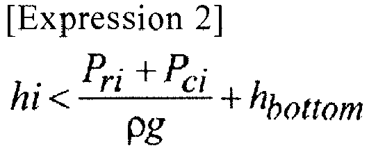
- the determination unit of the heat exchanger evaluating device may determine whether the refrigerant has accumulated in the heat exchanging unit on the basis of an expression below, given hi as the vertical height at the outlet of the heat exchanging unit, Pri as the first pressure loss, Pci as the second pressure loss, h bottom as the vertical height from the bottom edge of the heat exchanging unit to the vertically lowermost refrigerant flow path, p as a refrigerant density, and g as a gravitational acceleration.
- a second aspect of the present invention is a heat exchanger evaluating method of a heat exchanger including a heat exchanging unit that causes a refrigerant to circulate through a plurality of multistage refrigerant flow paths arranged in a vertical direction, and performs heat exchange between the refrigerant and air, a refrigerant header that allows the refrigerant in a gas phase to circulate therethrough and is connected to a first end side of each of the plurality of refrigerant flow paths, a plurality of refrigerant distribution tubes connected to respective second end sides of the plurality of refrigerant flow paths, and a refrigerant distributor that joins the plurality of refrigerant distribution tubes at a joining position.
- the heat exchanger evaluating method includes a first step of acquiring information on a vertical height of each of the refrigerant flow paths at an outlet of the heat exchanging unit of the heat exchanger to be evaluated, a first pressure loss of the refrigerant in the refrigerant flow paths of the heat exchanging unit, and a second pressure loss of the refrigerant in the refrigerant distribution tubes; and a second step of determining, for each of the refrigerant flow paths, whether the refrigerant has accumulated in the heat exchanging unit on the basis of a relationship between the vertical height of the refrigerant flow path of the heat exchanging unit, the first pressure loss, the second pressure loss, and a vertical height from a bottom edge of the heat exchanging unit to the vertically lowermost refrigerant flow path.
- the heat exchanger evaluating method may determine whether the refrigerant has accumulated in the heat exchanging unit on the basis of an expression below, given hi as the vertical height at the outlet of the heat exchanging unit, Pri as the first pressure loss, Pci as the second pressure loss, h bottom as the vertical height from the bottom edge of the heat exchanging unit to the vertically lowermost refrigerant flow path, p as a refrigerant density, and g as a gravitational acceleration.
- a third aspect of the present invention is a heat exchanger manufacturing method for a heat exchanger including a heat exchanging unit that causes a refrigerant to circulate through a plurality of multistage refrigerant flow paths arranged in a vertical direction, and performs heat exchange between the refrigerant and air, a refrigerant header that allows the refrigerant in a gas phase to circulate therethrough and is connected to a first end side of each of the plurality of refrigerant flow paths, a plurality of refrigerant distribution tubes connected to respective second end sides of the plurality of refrigerant flow paths, and a refrigerant distributor that joins the plurality of refrigerant distribution tubes at a joining position.
- the heat exchanger manufacturing method includes manufacturing the heat exchanger that satisfies an expression below, given hi as a vertical height of the refrigerant flow path at an outlet of the heat exchanging unit, Pri as a first pressure loss of the refrigerant in the refrigerant flow paths of the heat exchanging unit, Pci as a second pressure loss of the refrigerant in the refrigerant distribution tubes, h bottom as a vertical height from a bottom edge of the heat exchanging unit to the vertically lowermost refrigerant flow path, ⁇ as a refrigerant density, and g as a gravitational acceleration.
- a fourth aspect of the present invention is a heat exchanger designing method for a heat exchanger including a heat exchanging unit that causes a refrigerant to circulate through a plurality of multistage refrigerant flow paths arranged in a vertical direction, and performs heat exchange between the refrigerant and air, a refrigerant header that allows the refrigerant in a gas phase to circulate therethrough and is connected to a first end side of each of the plurality of refrigerant flow paths, a plurality of refrigerant distribution tubes connected to respective second end sides of the plurality of refrigerant flow paths, and a refrigerant distributor that joins the plurality of refrigerant distribution tubes at a joining position.
- the heat exchanger designing method includes designing the heat exchanger that satisfies an expression below, given hi as a vertical height of the refrigerant flow path at the outlet of the heat exchanging unit, Pri as a first pressure loss of the refrigerant in the refrigerant flow paths of the heat exchanging unit, Pci as a second pressure loss of the refrigerant in the refrigerant distribution tubes, h bottom as a vertical height from the bottom edge of the heat exchanging unit to the vertically lowermost refrigerant flow path, ⁇ as a refrigerant density, and g as a gravitational acceleration.
- the present invention achieves the effect of preventing a refrigerant from accumulating in a refrigerant flow path of a heat exchanger to the extent possible.
- a heat exchanger evaluating device, a heat exchanger evaluating method, a heat exchanger manufacturing method, and a heat exchanger designing method according to the present invention is described below with reference to the drawings.
- FIG. 1 illustrates a system configuration diagram of an evaluation system 3 of the present embodiment.
- the evaluation system 3 includes a heat exchanging system 1 and an evaluating device 30. While the evaluating device 30 according to the present embodiment may be used to evaluate an outdoor heat exchanger (heat exchanger) 100 or an indoor heat exchanger (heat exchanger) 200, the example described below is for evaluation of the outdoor heat exchanger 100.
- the heat exchanging system 1 is a system that connects the outdoor heat exchanger 100 and the indoor heat exchanger 200 by a refrigerant system to circulate the refrigerant.
- Examples of the heat exchanging system 1 include an air conditioning system in which one or a plurality of indoor heat exchangers are connected to a single outdoor heat exchanger.
- Other examples of the heat exchanging system 1 include a heat pump type hot water supply system that uses a CO2 refrigerant.
- the heat exchanging system 1 includes the outdoor heat exchanger 100, the indoor heat exchanger 200, a compressor 210 that compresses a refrigerant, an accumulator 220 that removes liquid components contained in a high-temperature, high-pressure refrigerant gas, a four-way valve 230, and an expansion valve 240, with these being connected by refrigerant piping.
- the heat exchanging system 1 illustrated in FIG. 1 allows selective execution of a cooling operation that cools an indoor area and a heating operation that heats an indoor area by switching a circulation direction of the refrigerant by the four-way valve 230.
- the four-way valve 230 sets the circulation direction of the refrigerant so that the refrigerant compressed by the compressor 210 is introduced into the indoor heat exchanger 200, causing the indoor heat exchanger 200 to function as a condenser, and the refrigerant heat-blocked and expanded by the expansion valve 240 is introduced into the outdoor heat exchanger 100, causing the outdoor heat exchanger 100 to function as an evaporator (the direction indicated by the solid arrows in FIG. 1 ).
- the four-way valve 230 sets the circulation direction of the refrigerant so that the refrigerant compressed by the compressor 210 is introduced into the outdoor heat exchanger 100, causing the outdoor heat exchanger 100 to function as a condenser, and the refrigerant heat-blocked and expanded by the expansion valve 240 is introduced into the indoor heat exchanger 200, causing the indoor heat exchanger 200 to function as an evaporator (the direction indicated by the dashed arrows in FIG. 1 ).
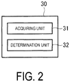
- the evaluating device 30 includes an acquiring unit 31 and a determination unit 32.
- FIG. 3 illustrates a refrigerant system of the outdoor heat exchanger 100 as viewed from the side.
- the acquiring unit 31 acquires information on vertical heights h 1 , h 2 , h i , h bottom of refrigerant flow paths 11, 12, 13, 14 at an outlet of the heat exchanging unit 10 of the heat exchanger (outdoor heat exchanger or indoor heat exchanger) to be evaluated from a bottom edge of a heat exchanging unit 10, a first pressure loss of the refrigerant in the refrigerant flow paths 11, 12, 13, 14 of the heat exchanging unit 10, and a second pressure loss of the refrigerant in capillary tubes 21 c1 , 21 c2 , 21 c1 ... 21 cbottom .
- the determination unit 32 determines, for each of the refrigerant flow paths 11, 12, 13, 14, whether refrigerant has accumulated in the heat exchanging unit 10 on the basis of the relationship of the vertical heights of the refrigerant flow paths 11, 12, 13, 14 at the outlet of the heat exchanging unit 10 from the bottom edge of the heat exchanging unit 10, the first pressure loss, the second pressure loss, and a vertical height from the bottom edge of the heat exchanging unit 10 to the vertically lowermost refrigerant flow path 14.
- the determination unit 32 determines whether refrigerant has accumulated in the heat exchanging unit on the basis of an expression below, given Pri as the first pressure loss, Pci as the second pressure loss, h bottom as the vertical height from the bottom edge of the heat exchanging unit 10 to the vertically lowermost refrigerant flow path 14, p as a refrigerant density, and g as a gravitational acceleration.
- the outdoor heat exchanger 100 includes the heat exchanging unit 10, the refrigerant distribution tubes 21, a refrigerant header 40, and a distributor (refrigerant distributor) 50.
- the heat exchanging unit 10 causes the refrigerant to circulate through the plurality of refrigerant flow paths (circuits) 11, 12, 13, 14 arranged in a vertical direction, and performs heat exchange with air blown by a blowing fan (not illustrated) provided to the outdoor heat exchanger 100.
- the refrigerant flow paths 11, 12, 13, 14 are tubular members formed by a metal member made of copper for example, and flow paths that circulate the refrigerant are formed in the interiors thereof.
- the heat exchanging unit 10 can be, for example, configured as a fin and tube type heat exchanger in which the plurality of refrigerant flow paths 11, 12, 13, 14 are inserted through insertion holes in a plurality of fins (not illustrated) having plate-like shapes, being made from aluminum, and being disposed consecutively in the horizontal direction.
- the refrigerant header 40 is piping that allows the refrigerant in a gas phase to circulate therethrough and is connected to a first end side of each of the plurality of refrigerant flow paths 11, 12, 13, 14 at a first connecting position C1.
- the refrigerant header 40 supplies the refrigerant in a gas phase to each of the plurality of refrigerant flow paths 11, 12, 13, 14.
- the refrigerant in a gas phase is supplied from each of the plurality of refrigerant flow paths 11, 12, 13, 14 to the refrigerant header 40.
- the refrigerant distribution tubes 21 include capillary tubes 21 c1 , 21 c2 , 21 ci ... 21 cbottom , each being connected to a second end side of the plurality of refrigerant flow paths 11, 12, 13, 14 at a second connecting position C2.
- the distributor 50 is a device that joins the capillary tubes 21 c1 , 21 c2 , 21 ci ... 21 cbottom at a joining position C3.
- the joining position C3 is disposed below the bottom edge of the heat exchanging unit 10 in a vertical direction (that is, up-down direction in FIG. 3 ) orthogonal to a mounting surface of the outdoor heat exchanger 100.
- the vertical heights of each of the refrigerant flow paths 11, 12, 13, 14 at the outlets of the heat exchanging unit 10 from the bottom surface of the heat exchanging unit 10 in the vertical direction (up-down direction in FIG. 3 ) orthogonal to the mounting surface of the outdoor heat exchanger 100 are set as heights h 1 , h 2 , h i , h bottom .
- FIG. 3 illustrates an example of a heat exchange model when the heat exchanger is used as a condenser.
- the up-down direction in FIG. 3 matches the vertical direction given the mounting surface on which the outdoor heat exchanger 100 is mounted as a reference.
- the heat exchanger is used as a condenser and therefore the refrigerant flows from left to right as viewed on the paper surface of FIG. 3 .
- the refrigerant passes through the refrigerant header 40 in a gas state, subsequently passes through the heat exchanging unit 10 in a two-phase state, and lastly passes through the capillary tubes 21 c1 , 21 c2 , 21 ci ... 21 cbottom in a liquid state, with the refrigerant from each of the refrigerant flow paths joining at the joining position C3 of the distributor 50.
- each subscript represents the number of refrigerant flow paths (circuits), and "bottom” refers to the lowermost refrigerant flow path.
- Pri denotes the pressure loss (Pa) in each of the refrigerant flow paths
- Pci denotes the pressure loss (Pa) in each of the capillary tubes
- h denotes the height (m) from the outlet of each of the refrigerant flow paths to the bottom edge of the heat exchanging unit 10
- h D denotes the height (m) from the bottom edge of the heat exchanging unit 10 to the bottom edge of the distributor 50
- Pin denotes the inlet pressure (Pa)
- Pout denotes the outlet pressure (Pa).
- the refrigerant header 40 In the refrigerant header 40, the refrigerant is in a gas state and therefore has low density. As a result, a position head pressure ⁇ gh is negligibly small compared to the pressure loss Pri in the refrigerant flow paths 11, 12, 13, 14 and the pressure loss Pci in the capillary tubes. Further, upon comparison with the refrigerant flow paths 11, 12, 13, 14, the refrigerant header 40 has a shorter piping length and a larger inner diameter than those of the refrigerant flow paths 11, 12, 13, 14, making the pressure loss in the refrigerant header 40 also negligibly small. Thus, the inlet pressures Pin of each of the refrigerant flow paths 11, 12, 13, 14 can be assumed as equal.
- the outlet pressures Pout of each of the refrigerant flow paths 11, 12, 13, 14 are designed as equal, and therefore the outlet pressures Pout can also be assumed as equal for the refrigerant flow paths 11, 12, 13, 14.
- the refrigerant in the capillary tubes 21 c1 , 21 c2 , 21 ci ,..., 21 cbottom is in a liquid state, and thus the refrigerant density ⁇ can be assumed as equal in the refrigerant flow paths 11, 12, 13, 14.
- Formula (2) the relationship between the inlet pressure Pin and the outlet pressure Pout is expressed as Formula (2) below from Formula (1).
- ⁇ is the refrigerant density (kg/m 3 )
- g is gravitational acceleration (m/s 2 ).
- the pressure loss is a function proportionate to the square of the refrigerant flow path Gr (kg/h) as shown below.
- ⁇ is a friction coefficient
- L is a piping length (m)
- d is a piping inner diameter (m)
- A is a piping cross-sectional area (m 2 )
- ⁇ L is a two-phase multiplier coefficient
- x is a dryness.
- P ⁇ L d G r 2 2 ⁇ A 2 Single phase region
- P ⁇ L 2 ⁇ L d 1 ⁇ x 2 2 ⁇ A 2 G r 2 Two-phase region , refrigerant flow path portion
- FIG. 4 illustrates an example of a heat exchange model when the heat exchanger is used as a condenser.
- the distributor 50 is disposed in a position above the bottom edge of the heat exchanging unit 10 in a vertical direction (that is, up-down direction in FIG. 4 ) orthogonal to the mounting surface of the outdoor heat exchanger 100.
- a vertical direction that is, up-down direction in FIG. 4
- the liquid head of the refrigerant at the capillary tube 21 cbottom of the lowermost refrigerant flow path 14 will be examined.
- the refrigerant moves upward and thus the liquid head works to decrease pressure.
- the refrigerant is positioned higher than a top edge of the distributor 50 at this time, the position decreases to the top edge of the distributor 50, causing the pressure to eventually increase by h D - h bottom .
- the relationship between the inlet pressure Pin and the outlet pressure Pout is expressed as follows.
- Formula (10) is equal to Formula (3) above. Accordingly, the exact same procedure as the process for deriving Formula (6) is used.
- Formula (10) is substituted into Formula (4), the formula becomes Formula (11) below, and Formula (11) and Formula (5) are exactly the same.
- Neither Formula (6) derived when the distributor 50 is assumed to be below the bottom edge of the heat exchanging unit 10 nor Formula (12) derived when the distributor 50 is assumed to be above the bottom edge of the heat exchanging unit 10 includes ho which represents the height from bottom edge of the heat exchanging unit 10 to the top edge of the distributor 50.
- liquid accumulation is not related to the height position of the distributor 50 when the heat exchanger is used as a condenser, and liquid accumulation will not occur as long as the sum of the pressure loss of each of the refrigerant flow paths 11, 12, 13, 14 and the pressure loss of each of the capillary tubes 21 c1 , 21 c2 , 21 ci ... 21 cbottom is greater than a liquid head pressure differential of each of the refrigerant flow paths 11, 12, 13, 14 and the lowermost refrigerant flow path 14.
- a heat exchanger already manufactured serves as the evaluation target, and the information acquired include the vertical height of the refrigerant flow paths 11, 12, 13, 14 at the outlets of the heat exchanging unit 10 of the heat exchanger to be evaluated, from the bottom edge of the heat exchanging unit 10, as well as the first pressure loss of the refrigerant in the refrigerant flow paths of the heat exchanging unit, and the second pressure loss of the refrigerant in the capillary tubes 21 c1 , 21 c2 , 21 ci ... 21 cbottom .
- each location may be adjusted so that Formula (7) holds.
- ways for remedying accumulation include changing the path assembly method of the refrigerant flow paths 11, 12, 13 of the heat exchanging unit 10 (that is, changing the circuit lengths of the heat exchanging unit 10), and adjusting the lengths of the capillary tubes 21 c1 , 21 c2 , 21 ci ... 21 cbottom .
- whether refrigerant has accumulated in the heat exchanging unit 10 is determined on the basis of the relationship between the vertical heights h 1 , h 2 , h i of the plurality of multistage refrigerant flow paths 11, 12, 13, arranged in the vertical direction, at the outlets of the heat exchanging unit 10, the first pressure loss of the refrigerant in the refrigerant flow paths 11, 12, 13, 14 in the heat exchanging unit 10 that performs heat exchange between the air and the refrigerant, the second pressure loss of the refrigerant in the capillary tubes 21 c1 , 21 c2 , 21 ci ... 21 cbottom , and the vertical height from the bottom edge of the heat exchanging unit 10 to the vertically lowermost multistage refrigerant flow path 14.
- outlet heights of the heat exchanging unit 10 for the refrigerant flow paths 11, 12, 13 above the refrigerant flow path 14 can be simply determined on the basis of the lowermost refrigerant flow path 14 using the expression for determining refrigerant accumulation.
- the heat exchanger When the heat exchanger is made to function as a condenser and subcooled liquid is determined to have accumulated in the heat exchanging unit 10, the accumulation in the heat exchanging unit can be eliminated and a decrease in a condensing capacity of the condenser can be prevented by adjusting the relationship between the heights of the refrigerant flow paths 11, 12, 13 of the heat exchanging unit 10, the pressure loss of the refrigerant in the heat exchanging unit 10, the pressure loss of the refrigerant in the refrigerant distribution tubes (capillary tubes) 21, and the height h cbottom of the lowermost refrigerant flow path 14.
- the evaluating device in the above embodiment has been described as a device that evaluates whether refrigerant has accumulated in the heat exchanging unit 10 for a heat exchanger that has already been manufactured, the present invention is not limited thereto.
- the evaluating device may be used in the stage of designing the heat exchanger.
- the evaluating device may be used in the stage of manufacturing the heat exchanger.
Landscapes
- Engineering & Computer Science (AREA)
- Physics & Mathematics (AREA)
- Mechanical Engineering (AREA)
- Thermal Sciences (AREA)
- General Engineering & Computer Science (AREA)
- Heat-Exchange Devices With Radiators And Conduit Assemblies (AREA)
- Other Air-Conditioning Systems (AREA)
Abstract
Description
- The present invention relates to a heat exchanger evaluating device, a heat exchanger evaluating method, a heat exchanger manufacturing method, and a heat exchanger designing method.
- A known heat exchanger is provided with a plurality of multistage refrigerant flow paths arranged independently in a vertical direction, and a refrigerant distributor to which a first end side of each of the plurality of refrigerant flow paths is connected via a capillary tube (refer to Patent Document 1, for example).
- Patent Document 1 discloses a method of adjusting a height from a bottom edge of a lowermost refrigerant flow path to a top edge of a lowermost capillary tube to prevent a liquid refrigerant from accumulating in the lowermost refrigerant flow path and causing an excessive increase in the degree of subcooling when the heat exchanger functions as a condenser.
- Patent Document 1:
JP 3985831 A - In Patent Document 1, the connecting positions of the plurality of refrigerant flow paths and the capillary tubes connected thereto are spaced apart at a constant interval across an entire region of the overall height of the heat exchanger in the vertical direction. As a result, a distance in the vertical direction between the connecting position of the uppermost refrigerant flow path and the capillary tube, and the connecting position of the lowermost refrigerant flow path and the capillary tube substantially matches the overall height of the heat exchanger.
- Thus, a large difference exists between the pressure of the liquid refrigerant from the connecting position of the uppermost refrigerant flow path to the refrigerant distributor caused by its own weight, and the pressure of the liquid refrigerant from the connecting position of the lowermost refrigerant flow path to the refrigerant distributor caused by its own weight. In consequence, the equalized pressure achieved after the liquid refrigerants from the plurality of capillary tubes join together in the refrigerant distributor increases, making it difficult for the liquid refrigerant to discharge from the lowermost refrigerant flow path to the capillary tube and resulting in problematic accumulation of liquid refrigerant in the interior of the refrigerant flow path.
- In light of the foregoing, an object of the present invention is to provide a heat exchanger evaluating device, a heat exchanger evaluating method, a heat exchanger manufacturing method, and a heat exchanger designing method capable of significantly preventing a refrigerant from accumulating in a refrigerant flow path of a heat exchanger.
- A first aspect of the present invention is a heat exchanger evaluating device for a heat exchanger including a heat exchanging unit that causes a refrigerant to circulate through a plurality of multistage refrigerant flow paths arranged in a vertical direction, and performs heat exchange between the refrigerant and air, a refrigerant header that allows the refrigerant in a gas phase to circulate therethrough and is connected to a first end side of each of the plurality of refrigerant flow paths, a plurality of refrigerant distribution tubes connected to respective second end sides of the plurality of refrigerant flow paths, and a refrigerant distributor that joins the plurality of refrigerant distribution tubes at a joining position. The heat exchanger evaluating device is provided with a determination unit that determines, for each of the refrigerant flow paths, whether the refrigerant has accumulated in the heat exchanging unit on the basis of a relationship between a vertical height of the refrigerant flow path at an outlet of the heat exchanging unit, a first pressure loss of the refrigerant in the refrigerant flow path of the heat exchanging unit, a second pressure loss of the refrigerant in the corresponding refrigerant distribution tube, and a vertical height from a bottom edge of the heat exchanging unit to the vertically lowermost refrigerant flow path.
- According to the first aspect of the present invention, it is determined, for each of the plurality of multistage refrigerant flow paths arranged in the vertical direction, whether the refrigerant has accumulated in the heat exchanging unit on the basis of a relationship between the vertical height of the refrigerant flow path at the outlet of the heat exchanging unit, the first pressure loss of the refrigerant in the refrigerant flow path of the heat exchanging unit that performs heat exchange between the air and the refrigerant, the second pressure loss of the refrigerant in the refrigerant distribution tube, and the vertical height from the bottom edge of the heat exchanging unit to the vertically lowermost multistage refrigerant flow path.
- Thus, whether the refrigerant has accumulated in the heat exchanging unit can be simply determined using the information of each location through which the refrigerant passes.
- When the heat exchanging unit is made to function as a condenser and subcooled liquid is determined to have accumulated in the heat exchanging unit, the accumulation in the heat exchanging unit can be eliminated and a decrease in a condensing capacity of the condenser can be prevented by adjusting the relationship between the height of the refrigerant flow path of the heat exchanging unit, the pressure loss of the refrigerant in the heat exchanging unit, the pressure loss of the refrigerant in the refrigerant distribution tubes, and the height of the lowermost refrigerant flow path.
- The determination unit of the heat exchanger evaluating device according to the first aspect of the present invention may determine whether the refrigerant has accumulated in the heat exchanging unit on the basis of an expression below, given hi as the vertical height at the outlet of the heat exchanging unit, Pri as the first pressure loss, Pci as the second pressure loss, hbottom as the vertical height from the bottom edge of the heat exchanging unit to the vertically lowermost refrigerant flow path, p as a refrigerant density, and g as a gravitational acceleration.

- This determination is simply made on the basis of the conditional expression.
- A second aspect of the present invention is a heat exchanger evaluating method of a heat exchanger including a heat exchanging unit that causes a refrigerant to circulate through a plurality of multistage refrigerant flow paths arranged in a vertical direction, and performs heat exchange between the refrigerant and air, a refrigerant header that allows the refrigerant in a gas phase to circulate therethrough and is connected to a first end side of each of the plurality of refrigerant flow paths, a plurality of refrigerant distribution tubes connected to respective second end sides of the plurality of refrigerant flow paths, and a refrigerant distributor that joins the plurality of refrigerant distribution tubes at a joining position. The heat exchanger evaluating method includes a first step of acquiring information on a vertical height of each of the refrigerant flow paths at an outlet of the heat exchanging unit of the heat exchanger to be evaluated, a first pressure loss of the refrigerant in the refrigerant flow paths of the heat exchanging unit, and a second pressure loss of the refrigerant in the refrigerant distribution tubes; and a second step of determining, for each of the refrigerant flow paths, whether the refrigerant has accumulated in the heat exchanging unit on the basis of a relationship between the vertical height of the refrigerant flow path of the heat exchanging unit, the first pressure loss, the second pressure loss, and a vertical height from a bottom edge of the heat exchanging unit to the vertically lowermost refrigerant flow path.
- The heat exchanger evaluating method may determine whether the refrigerant has accumulated in the heat exchanging unit on the basis of an expression below, given hi as the vertical height at the outlet of the heat exchanging unit, Pri as the first pressure loss, Pci as the second pressure loss, hbottom as the vertical height from the bottom edge of the heat exchanging unit to the vertically lowermost refrigerant flow path, p as a refrigerant density, and g as a gravitational acceleration.

- A third aspect of the present invention is a heat exchanger manufacturing method for a heat exchanger including a heat exchanging unit that causes a refrigerant to circulate through a plurality of multistage refrigerant flow paths arranged in a vertical direction, and performs heat exchange between the refrigerant and air, a refrigerant header that allows the refrigerant in a gas phase to circulate therethrough and is connected to a first end side of each of the plurality of refrigerant flow paths, a plurality of refrigerant distribution tubes connected to respective second end sides of the plurality of refrigerant flow paths, and a refrigerant distributor that joins the plurality of refrigerant distribution tubes at a joining position. The heat exchanger manufacturing method includes manufacturing the heat exchanger that satisfies an expression below, given hi as a vertical height of the refrigerant flow path at an outlet of the heat exchanging unit, Pri as a first pressure loss of the refrigerant in the refrigerant flow paths of the heat exchanging unit, Pci as a second pressure loss of the refrigerant in the refrigerant distribution tubes, hbottom as a vertical height from a bottom edge of the heat exchanging unit to the vertically lowermost refrigerant flow path, ρ as a refrigerant density, and g as a gravitational acceleration.

- A fourth aspect of the present invention is a heat exchanger designing method for a heat exchanger including a heat exchanging unit that causes a refrigerant to circulate through a plurality of multistage refrigerant flow paths arranged in a vertical direction, and performs heat exchange between the refrigerant and air, a refrigerant header that allows the refrigerant in a gas phase to circulate therethrough and is connected to a first end side of each of the plurality of refrigerant flow paths, a plurality of refrigerant distribution tubes connected to respective second end sides of the plurality of refrigerant flow paths, and a refrigerant distributor that joins the plurality of refrigerant distribution tubes at a joining position. The heat exchanger designing method includes designing the heat exchanger that satisfies an expression below, given hi as a vertical height of the refrigerant flow path at the outlet of the heat exchanging unit, Pri as a first pressure loss of the refrigerant in the refrigerant flow paths of the heat exchanging unit, Pci as a second pressure loss of the refrigerant in the refrigerant distribution tubes, hbottom as a vertical height from the bottom edge of the heat exchanging unit to the vertically lowermost refrigerant flow path, ρ as a refrigerant density, and g as a gravitational acceleration.

- The present invention achieves the effect of preventing a refrigerant from accumulating in a refrigerant flow path of a heat exchanger to the extent possible.
-
-
FIG. 1 is a system configuration diagram of a heat exchanging system according to the present invention. -
FIG. 2 is a function block diagram of an evaluating device according to the present invention. -
FIG. 3 illustrates an example of a heat exchange model during use as a condenser in a case where a distributer is below a bottom surface of a heat exchanger. -
FIG. 4 illustrates an example of a heat exchange model during use as a condenser in a case where the distributer is above the bottom surface of the heat exchanger. - A heat exchanger evaluating device, a heat exchanger evaluating method, a heat exchanger manufacturing method, and a heat exchanger designing method according to the present invention is described below with reference to the drawings.
-
FIG. 1 illustrates a system configuration diagram of anevaluation system 3 of the present embodiment. Theevaluation system 3 includes a heat exchanging system 1 and an evaluatingdevice 30. While the evaluatingdevice 30 according to the present embodiment may be used to evaluate an outdoor heat exchanger (heat exchanger) 100 or an indoor heat exchanger (heat exchanger) 200, the example described below is for evaluation of theoutdoor heat exchanger 100. - The heat exchanging system 1 is a system that connects the
outdoor heat exchanger 100 and theindoor heat exchanger 200 by a refrigerant system to circulate the refrigerant. - Examples of the heat exchanging system 1 include an air conditioning system in which one or a plurality of indoor heat exchangers are connected to a single outdoor heat exchanger. Other examples of the heat exchanging system 1 include a heat pump type hot water supply system that uses a CO2 refrigerant.
- As illustrated in the system configuration diagram in
FIG. 1 , the heat exchanging system 1 includes theoutdoor heat exchanger 100, theindoor heat exchanger 200, acompressor 210 that compresses a refrigerant, anaccumulator 220 that removes liquid components contained in a high-temperature, high-pressure refrigerant gas, a four-way valve 230, and anexpansion valve 240, with these being connected by refrigerant piping. - The heat exchanging system 1 illustrated in
FIG. 1 allows selective execution of a cooling operation that cools an indoor area and a heating operation that heats an indoor area by switching a circulation direction of the refrigerant by the four-way valve 230. - When the heating operation is performed, the four-
way valve 230 sets the circulation direction of the refrigerant so that the refrigerant compressed by thecompressor 210 is introduced into theindoor heat exchanger 200, causing theindoor heat exchanger 200 to function as a condenser, and the refrigerant heat-blocked and expanded by theexpansion valve 240 is introduced into theoutdoor heat exchanger 100, causing theoutdoor heat exchanger 100 to function as an evaporator (the direction indicated by the solid arrows inFIG. 1 ). - On the other hand, when the cooling operation is performed, the four-
way valve 230 sets the circulation direction of the refrigerant so that the refrigerant compressed by thecompressor 210 is introduced into theoutdoor heat exchanger 100, causing theoutdoor heat exchanger 100 to function as a condenser, and the refrigerant heat-blocked and expanded by theexpansion valve 240 is introduced into theindoor heat exchanger 200, causing theindoor heat exchanger 200 to function as an evaporator (the direction indicated by the dashed arrows inFIG. 1 ). - As illustrated in
FIG. 2 , the evaluatingdevice 30 includes an acquiringunit 31 and adetermination unit 32.FIG. 3 illustrates a refrigerant system of theoutdoor heat exchanger 100 as viewed from the side. - The acquiring
unit 31 acquires information on vertical heights h1, h2, hi, hbottom ofrefrigerant flow paths heat exchanging unit 10 of the heat exchanger (outdoor heat exchanger or indoor heat exchanger) to be evaluated from a bottom edge of aheat exchanging unit 10, a first pressure loss of the refrigerant in therefrigerant flow paths heat exchanging unit 10, and a second pressure loss of the refrigerant incapillary tubes - The
determination unit 32 determines, for each of therefrigerant flow paths heat exchanging unit 10 on the basis of the relationship of the vertical heights of therefrigerant flow paths heat exchanging unit 10 from the bottom edge of theheat exchanging unit 10, the first pressure loss, the second pressure loss, and a vertical height from the bottom edge of theheat exchanging unit 10 to the vertically lowermostrefrigerant flow path 14. Specifically, thedetermination unit 32 determines whether refrigerant has accumulated in the heat exchanging unit on the basis of an expression below, given Pri as the first pressure loss, Pci as the second pressure loss, hbottom as the vertical height from the bottom edge of theheat exchanging unit 10 to the vertically lowermostrefrigerant flow path 14, p as a refrigerant density, and g as a gravitational acceleration.

- The basis for use of the formula above is explained below.
- When the Distributer is Below the Bottom Surface of the Heat Exchanging Unit:
As illustrated inFIG. 3 , theoutdoor heat exchanger 100 includes theheat exchanging unit 10, therefrigerant distribution tubes 21, arefrigerant header 40, and a distributor (refrigerant distributor) 50. - The
heat exchanging unit 10 causes the refrigerant to circulate through the plurality of refrigerant flow paths (circuits) 11, 12, 13, 14 arranged in a vertical direction, and performs heat exchange with air blown by a blowing fan (not illustrated) provided to theoutdoor heat exchanger 100. - The
refrigerant flow paths - The
heat exchanging unit 10 can be, for example, configured as a fin and tube type heat exchanger in which the plurality ofrefrigerant flow paths - The
refrigerant header 40 is piping that allows the refrigerant in a gas phase to circulate therethrough and is connected to a first end side of each of the plurality ofrefrigerant flow paths - When the outdoor heat exchanger 100 functions as a condenser, the
refrigerant header 40 supplies the refrigerant in a gas phase to each of the plurality ofrefrigerant flow paths outdoor heat exchanger 100 functions as an evaporator, the refrigerant in a gas phase is supplied from each of the plurality ofrefrigerant flow paths refrigerant header 40. - The
refrigerant distribution tubes 21 includecapillary tubes refrigerant flow paths - The
distributor 50 is a device that joins thecapillary tubes heat exchanging unit 10 in a vertical direction (that is, up-down direction inFIG. 3 ) orthogonal to a mounting surface of theoutdoor heat exchanger 100. - When the
outdoor heat exchanger 100 functions as a condenser, subcooled liquid discharged from the second connecting positions C2 of the plurality ofrefrigerant flow paths capillary tubes distributor 50. - On the other hand, when the
outdoor heat exchanger 100 functions as an evaporator, subcooled liquid discharged from the joining position C3 of thedistributor 50 is guided to thecapillary tubes refrigerant flow paths - As illustrated in
FIG. 3 , the vertical heights of each of therefrigerant flow paths heat exchanging unit 10 from the bottom surface of theheat exchanging unit 10 in the vertical direction (up-down direction inFIG. 3 ) orthogonal to the mounting surface of theoutdoor heat exchanger 100 are set as heights h1, h2, hi, hbottom. -
FIG. 3 illustrates an example of a heat exchange model when the heat exchanger is used as a condenser. The up-down direction inFIG. 3 matches the vertical direction given the mounting surface on which theoutdoor heat exchanger 100 is mounted as a reference. - In the present embodiment, the heat exchanger is used as a condenser and therefore the refrigerant flows from left to right as viewed on the paper surface of
FIG. 3 . The refrigerant passes through therefrigerant header 40 in a gas state, subsequently passes through theheat exchanging unit 10 in a two-phase state, and lastly passes through thecapillary tubes distributor 50. - In
FIG. 3 , each subscript represents the number of refrigerant flow paths (circuits), and "bottom" refers to the lowermost refrigerant flow path. Here, Pri denotes the pressure loss (Pa) in each of the refrigerant flow paths, Pci denotes the pressure loss (Pa) in each of the capillary tubes, h denotes the height (m) from the outlet of each of the refrigerant flow paths to the bottom edge of theheat exchanging unit 10, hD denotes the height (m) from the bottom edge of theheat exchanging unit 10 to the bottom edge of thedistributor 50, Pin denotes the inlet pressure (Pa), and Pout denotes the outlet pressure (Pa). - In the
refrigerant header 40, the refrigerant is in a gas state and therefore has low density. As a result, a position head pressure ρgh is negligibly small compared to the pressure loss Pri in therefrigerant flow paths refrigerant flow paths refrigerant header 40 has a shorter piping length and a larger inner diameter than those of therefrigerant flow paths refrigerant header 40 also negligibly small. Thus, the inlet pressures Pin of each of therefrigerant flow paths - Further, the outlet pressures Pout of each of the
refrigerant flow paths refrigerant flow paths heat exchanging unit 10, the refrigerant in thecapillary tubes refrigerant flow paths - From the above assumed conditions, the relationship between the inlet pressure Pin and the outlet pressure Pout is expressed as Formula (2) below from Formula (1). Here, ρ is the refrigerant density (kg/m3), and g is gravitational acceleration (m/s2).
- [Expression 6]

- Here, the relationship between the uppermost
refrigerant flow path 11 and the lowermostrefrigerant flow path 14 will be examined. Because the outlet outputs Pout are equal for each of the refrigerant flow paths, Formulas (1) and (2) above are equal. Thus, Formula (3) below holds.
[Expression 7]
- Here, the pressure loss is a function proportionate to the square of the refrigerant flow path Gr (kg/h) as shown below. Note that λ is a friction coefficient, L is a piping length (m), d is a piping inner diameter (m), A is a piping cross-sectional area (m2), ϕL is a two-phase multiplier coefficient, and x is a dryness.

- Thus, the refrigerant flows to the lowermost
refrigerant flow path 14 as long as Prbottom > 0, and to the lowermostcapillary tube 21cbottom as long as Pcbottom > 0. As a result, the conditional expression for the flow of refrigerant without liquid accumulation in the lowermostrefrigerant flow path 14 is Formula (4) below.
[Expression 9]
- When Formula (3) is substituted into Formula (4) described above, Formula (5) below is achieved.
[Expression 10]
- From Formula (5) above, it is understood that a flow of refrigerant will exist in the lowermost
refrigerant flow path 14 and liquid accumulation will not occur as long as the sum of the pressure loss of the uppermostrefrigerant flow path 11 and the pressure loss of thecapillary tube 21c1 is greater than a liquid head pressure differential of the uppermostrefrigerant flow path 11 and the lowermostrefrigerant flow path 14. The relationships between the second and subsequentrefrigerant flow paths refrigerant flow path 14 can also each be found using a similar procedure. From this, it is understood that liquid accumulation will not occur in the lowermostrefrigerant flow path 14 as long as Formula (6) below (Formula (7) upon conversion) is satisfied in all of therefrigerant flow paths
[Expression 11]

- When the Distributer is Above the Bottom Surface of the Heat Exchanging Unit:
-
FIG. 4 illustrates an example of a heat exchange model when the heat exchanger is used as a condenser. UnlikeFIG. 3 , thedistributor 50 is disposed in a position above the bottom edge of theheat exchanging unit 10 in a vertical direction (that is, up-down direction inFIG. 4 ) orthogonal to the mounting surface of theoutdoor heat exchanger 100. In the following, descriptions of locations having the same configuration as that inFIG. 3 will be omitted, and differences therebetween will be mainly described. - Here, the liquid head of the refrigerant at the
capillary tube 21cbottom of the lowermostrefrigerant flow path 14 will be examined. In the lowermostrefrigerant flow path 14, the refrigerant moves upward and thus the liquid head works to decrease pressure. While the refrigerant is positioned higher than a top edge of thedistributor 50 at this time, the position decreases to the top edge of thedistributor 50, causing the pressure to eventually increase by hD - hbottom. Thus, the relationship between the inlet pressure Pin and the outlet pressure Pout is expressed as follows. - [Expression 12]

- Similar to the case where the
distributor 50 is below the bottom edge of theheat exchanging unit 10, the outlet pressure Pout are equal for each of therefrigerant flow paths
[Expression 13]
- Here, Formula (10) is equal to Formula (3) above. Accordingly, the exact same procedure as the process for deriving Formula (6) is used. When Formula (10) is substituted into Formula (4), the formula becomes Formula (11) below, and Formula (11) and Formula (5) are exactly the same.
[Expression 14]
- When the second and subsequent
refrigerant flow paths refrigerant flow path 14 are treated in the same manner, Formula (12) is found, and Formulas (12) and (6) are the same. It is then understood that liquid accumulation will not occur in the lowermostrefrigerant flow path 14 as long as Formula (12) (Formula (13) upon conversion) is satisfied in all of therefrigerant flow paths
[Expression 15]

- Neither Formula (6) derived when the
distributor 50 is assumed to be below the bottom edge of theheat exchanging unit 10 nor Formula (12) derived when thedistributor 50 is assumed to be above the bottom edge of theheat exchanging unit 10 includes ho which represents the height from bottom edge of theheat exchanging unit 10 to the top edge of thedistributor 50. - This indicates that liquid accumulation is not related to the height position of the
distributor 50 when the heat exchanger is used as a condenser, and liquid accumulation will not occur as long as the sum of the pressure loss of each of therefrigerant flow paths capillary tubes refrigerant flow paths refrigerant flow path 14. - The action of the evaluating
device 30 of an air-conditioning device according to the present embodiment will be described below with reference toFIGS. 1 to 4 . - A heat exchanger already manufactured serves as the evaluation target, and the information acquired include the vertical height of the
refrigerant flow paths heat exchanging unit 10 of the heat exchanger to be evaluated, from the bottom edge of theheat exchanging unit 10, as well as the first pressure loss of the refrigerant in the refrigerant flow paths of the heat exchanging unit, and the second pressure loss of the refrigerant in thecapillary tubes - Whether refrigerant has accumulated in the
heat exchanging unit 10 is determined in accordance with whether Formula (7) (Formula (13)) holds on the basis of the acquired information. - When Formula (7) holds, it is determined that refrigerant has not accumulated in the
heat exchanging unit 10. When Formula (7) does not hold, it is determined that refrigerant has accumulated in theheat exchanging unit 10. - When it has been determined that refrigerant has accumulated in the
heat exchanging unit 10, the value of each location may be adjusted so that Formula (7) holds. Examples of ways for remedying accumulation include changing the path assembly method of therefrigerant flow paths capillary tubes - As described above, according to the heat exchanger (
outdoor heat exchanger 100 and indoor heat exchanger 200) evaluating device, the heat exchanger evaluating method, the heat exchanging manufacturing method, and the heat exchanger designing method according to the present embodiment, whether refrigerant has accumulated in theheat exchanging unit 10 is determined on the basis of the relationship between the vertical heights h1, h2, hi of the plurality of multistagerefrigerant flow paths heat exchanging unit 10, the first pressure loss of the refrigerant in therefrigerant flow paths heat exchanging unit 10 that performs heat exchange between the air and the refrigerant, the second pressure loss of the refrigerant in thecapillary tubes heat exchanging unit 10 to the vertically lowermost multistagerefrigerant flow path 14. - Thus, whether refrigerant has accumulated in the
heat exchanging unit 10 can be simply determined using the information of each location through which the refrigerant passes. - Further, the outlet heights of the
heat exchanging unit 10 for therefrigerant flow paths refrigerant flow path 14 can be simply determined on the basis of the lowermostrefrigerant flow path 14 using the expression for determining refrigerant accumulation. - When the heat exchanger is made to function as a condenser and subcooled liquid is determined to have accumulated in the
heat exchanging unit 10, the accumulation in the heat exchanging unit can be eliminated and a decrease in a condensing capacity of the condenser can be prevented by adjusting the relationship between the heights of therefrigerant flow paths heat exchanging unit 10, the pressure loss of the refrigerant in theheat exchanging unit 10, the pressure loss of the refrigerant in the refrigerant distribution tubes (capillary tubes) 21, and the height hcbottom of the lowermostrefrigerant flow path 14. - While the evaluating device in the above embodiment has been described as a device that evaluates whether refrigerant has accumulated in the
heat exchanging unit 10 for a heat exchanger that has already been manufactured, the present invention is not limited thereto. For example, the evaluating device may be used in the stage of designing the heat exchanger. - Specifically, when the information on the height hi of each of the
refrigerant flow paths refrigerant flow paths capillary tubes refrigerant flow path 14 from theheat exchanging unit 10 derived in the design stage is substituted into Formula (7) above and Formula (7) holds, no refrigerant accumulation is assumed, and the design process transitions to another design process or the like. When Formula (7) above does not hold, refrigerant accumulation is assumed to have occurred, and the accumulation can be remedied by returning to the design procedure, adjusting the heights h1, h2, hi, hbottom of each of therefrigerant flow paths heat exchanging unit 10, adjusting the circuit lengths, and reselecting thecapillary tubes - Additionally, as another example, the evaluating device may be used in the stage of manufacturing the heat exchanger.
- Specifically, when the information on the height hi of each of the
refrigerant flow paths refrigerant flow paths capillary tubes refrigerant flow path 14 from theheat exchanging unit 10 obtained in the manufacturing stage is substituted into Formula (7) above and Formula (7) holds, no refrigerant accumulation is assumed and the manufacturing process proceeds. - When Formula (7) above does not hold, it is determined that refrigerant accumulation has occurred. The heat exchanger can then be manufactured so that Formula (7) above holds by adjusting the heights h1, h2, hi, hbottom of each of the
refrigerant flow paths heat exchanging unit 10, adjusting the circuit lengths, and reselecting thecapillary tubes - The embodiment of the present invention has been described above in detail with reference to the drawings, but the specific configurations are not limited to the embodiment, and design changes and the like that do not depart from the scope of the present invention are also included.
-
- 1 Heat exchanging system
- 10 Heat exchanging unit
- 11, 12, 13, 14 Refrigerant flow path
- 21c1, 21c2, 21ci... 21cbottom Capillary tube
- 40 Refrigerant header
- 50 Distributor (refrigerant distributor)
- 100 Outdoor heat exchanger (heat exchanger)
- 200 Indoor heat exchanger (heat exchanger)
Claims (6)
- A heat exchanger evaluating device for a heat exchanger comprising:a heat exchanging unit that causes a refrigerant to circulate through a plurality of multistage refrigerant flow paths arranged in a vertical direction, and performs heat exchange between the refrigerant and air;a refrigerant header that allows the refrigerant in a gas phase to circulate therethrough and is connected to a first end side of each of the plurality of refrigerant flow paths;a plurality of refrigerant distribution tubes connected to respective second end sides of the plurality of refrigerant flow paths; anda refrigerant distributor that joins the plurality of refrigerant distribution tubes at a joining position; the heat exchanger evaluating device comprising:a determination unit that determines, for each of the refrigerant flow paths, whether the refrigerant has accumulated in the heat exchanging unit on the basis of a relationship between a vertical height of the refrigerant flow path at an outlet of the heat exchanging unit, a first pressure loss of the refrigerant in the refrigerant flow path of the heat exchanging unit, a second pressure loss of the refrigerant in the corresponding refrigerant distribution tube, and a vertical height from a bottom edge of the heat exchanging unit to the vertically lowermost refrigerant flow path.
- The heat exchanger evaluating device according to claim 1, wherein the determination unit determines whether the refrigerant has accumulated in the heat exchanging unit on the basis of an expression below, given hi as the vertical height at the outlet of the heat exchanging unit, Pri as the first pressure loss, Pci as the second pressure loss, hbottom as the vertical height from the bottom edge of the heat exchanging unit to the vertically lowermost refrigerant flow path, p as a refrigerant density, and g as a gravitational acceleration:

- A heat exchanger evaluating method of a heat exchanger comprising a heat exchanging unit that causes a refrigerant to circulate through a plurality of multistage refrigerant flow paths arranged in a vertical direction, and performs heat exchange between the refrigerant and air, a refrigerant header that allows the refrigerant in a gas phase to circulate therethrough and is connected to a first end side of each of the plurality of refrigerant flow paths, a plurality of refrigerant distribution tubes connected to respective second end sides of the plurality of refrigerant flow paths, and a refrigerant distributor that joins the plurality of refrigerant distribution tubes at a joining position, the heat exchanger evaluating method comprising:a first step of acquiring information on a vertical height of each of the refrigerant flow paths at an outlet of the heat exchanging unit of the heat exchanger to be evaluated, a first pressure loss of the refrigerant in the refrigerant flow paths of the heat exchanging unit, and a second pressure loss of the refrigerant in the refrigerant distribution tubes; anda second step of determining, for each of the refrigerant flow paths, whether the refrigerant has accumulated in the heat exchanging unit on the basis of a relationship between the vertical height of the refrigerant flow path of the heat exchanging unit, the first pressure loss, the second pressure loss, and a vertical height from a bottom edge of the heat exchanging unit to the vertically lowermost refrigerant flow path.
- The heat exchanger evaluating method according to claim 3, wherein whether the refrigerant has accumulated in the heat exchanging unit is determined on the basis of an expression below, given hi as the vertical height at the outlet of the heat exchanging unit, Pri as the first pressure loss, Pci as the second pressure loss, hbottom as the vertical height from the bottom edge of the heat exchanging unit to the vertically lowermost refrigerant flow path, p as a refrigerant density, and g as a gravitational acceleration:
- A heat exchanger manufacturing method for a heat exchanger comprising a heat exchanging unit that causes a refrigerant to circulate through a plurality of multistage refrigerant flow paths arranged in a vertical direction, and performs heat exchange between the refrigerant and air, a refrigerant header that allows the refrigerant in a gas phase to circulate therethrough and is connected to a first end side of each of the plurality of refrigerant flow paths, a plurality of refrigerant distribution tubes connected to respective second end sides of the plurality of refrigerant flow paths, and a refrigerant distributor that joins the plurality of refrigerant distribution tubes at a joining position, the heat exchanger manufacturing method comprising:manufacturing the heat exchanger that satisfies an expression below, given hi as a vertical height of the refrigerant flow path at an outlet of the heat exchanging unit, Pri as a first pressure loss of the refrigerant in the refrigerant flow paths of the heat exchanging unit, Pci as a second pressure loss of the refrigerant in the refrigerant distribution tubes, hbottom as a vertical height from the bottom edge of the heat exchanging unit to the vertically lowermost refrigerant flow path, ρ as a refrigerant density, and g as a gravitational acceleration:

- A heat exchanger designing method for a heat exchanger comprising a heat exchanging unit that causes a refrigerant to circulate through a plurality of multistage refrigerant flow paths arranged in a vertical direction, and performs heat exchange between the refrigerant and air, a refrigerant header that allows the refrigerant in a gas phase to circulate therethrough and is connected to a first end side of each of the plurality of refrigerant flow paths, a plurality of refrigerant distribution tubes connected to respective second end sides of the plurality of refrigerant flow paths, and a refrigerant distributor that joins the plurality of refrigerant distribution tubes at a joining position, the heat exchanger designing method comprising:designing the heat exchanger that satisfies an expression below, given hi as a vertical height of the refrigerant flow path at an outlet of the heat exchanging unit, Pri as a first pressure loss of the refrigerant in the refrigerant flow paths of the heat exchanging unit, Pci as a second pressure loss of the refrigerant in the refrigerant distribution tubes, hbottom as a vertical height from the bottom edge of the heat exchanging unit to the vertically lowermost refrigerant flow path, ρ as a refrigerant density, and g as a gravitational acceleration:

Applications Claiming Priority (2)
| Application Number | Priority Date | Filing Date | Title |
|---|---|---|---|
| JP2016050950A JP2017166728A (en) | 2016-03-15 | 2016-03-15 | Heat exchanger evaluation device, heat exchanger evaluation method, heat exchanger manufacturing method, and heat exchanger design method |
| PCT/JP2017/009351 WO2017159515A1 (en) | 2016-03-15 | 2017-03-09 | Heat exchanger evaluating device, heat exchanger evaluating method, heat exchanger manufacturing method, and heat exchanger designing method |
Publications (2)
| Publication Number | Publication Date |
|---|---|
| EP3431904A1 true EP3431904A1 (en) | 2019-01-23 |
| EP3431904A4 EP3431904A4 (en) | 2019-04-17 |
Family
ID=59851509
Family Applications (1)
| Application Number | Title | Priority Date | Filing Date |
|---|---|---|---|
| EP17766516.3A Withdrawn EP3431904A4 (en) | 2016-03-15 | 2017-03-09 | HEAT EXCHANGER EVALUATION DEVICE AND METHOD, HEAT EXCHANGER MANUFACTURING METHOD, AND HEAT EXCHANGER DESIGN METHOD |
Country Status (4)
| Country | Link |
|---|---|
| EP (1) | EP3431904A4 (en) |
| JP (1) | JP2017166728A (en) |
| CN (1) | CN108474597A (en) |
| WO (1) | WO2017159515A1 (en) |
Family Cites Families (6)
| Publication number | Priority date | Publication date | Assignee | Title |
|---|---|---|---|---|
| JP3985831B2 (en) * | 2005-10-31 | 2007-10-03 | ダイキン工業株式会社 | Heat exchanger for outdoor unit |
| JP6064412B2 (en) * | 2012-07-30 | 2017-01-25 | 株式会社富士通ゼネラル | Air conditioner |
| EP2924368B1 (en) * | 2012-11-22 | 2019-02-06 | Mitsubishi Electric Corporation | Air conditioner and operation control method therefor |
| JP5790730B2 (en) * | 2012-12-25 | 2015-10-07 | ダイキン工業株式会社 | Heat exchanger |
| US9829230B2 (en) * | 2013-02-28 | 2017-11-28 | Mitsubishi Electric Corporation | Air conditioning apparatus |
| JP5984872B2 (en) * | 2014-05-13 | 2016-09-06 | 三菱電機株式会社 | Fuel supply device |
-
2016
- 2016-03-15 JP JP2016050950A patent/JP2017166728A/en active Pending
-
2017
- 2017-03-09 CN CN201780005295.3A patent/CN108474597A/en active Pending
- 2017-03-09 EP EP17766516.3A patent/EP3431904A4/en not_active Withdrawn
- 2017-03-09 WO PCT/JP2017/009351 patent/WO2017159515A1/en not_active Ceased
Also Published As
| Publication number | Publication date |
|---|---|
| CN108474597A (en) | 2018-08-31 |
| JP2017166728A (en) | 2017-09-21 |
| WO2017159515A1 (en) | 2017-09-21 |
| EP3431904A4 (en) | 2019-04-17 |
Similar Documents
| Publication | Publication Date | Title |
|---|---|---|
| US9651317B2 (en) | Heat exchanger and air conditioner | |
| EP3232139B1 (en) | Heat exchanger of an air-conditioning device | |
| EP3009771B1 (en) | Air-conditioning device | |
| US20210310672A1 (en) | Air-conditioning apparatus and method of using air-conditioning apparatus | |
| US9551539B2 (en) | Heat exchanger and manufacturing method thereof | |
| EP3569938B1 (en) | Air conditioner | |
| US11543185B2 (en) | Air-conditioning apparatus | |
| EP3264010A1 (en) | Heat exchange apparatus and air conditioner using same | |
| AU2022267168B2 (en) | Pipe Coupling Structure and Refrigeration Cycle Apparatus | |
| EP3062037A1 (en) | Heat exchanger and refrigeration cycle device using said heat exchanger | |
| WO2019039401A1 (en) | Condenser | |
| JP5677220B2 (en) | Refrigeration cycle equipment | |
| EP4043813A1 (en) | Cooling device | |
| US12152841B2 (en) | Refrigeration cycle apparatus | |
| JP6273838B2 (en) | Heat exchanger | |
| AU2017444848B2 (en) | Heat exchanger and refrigeration cycle device | |
| JPWO2017208419A1 (en) | Fin tube type heat exchanger and heat pump device provided with the fin tube type heat exchanger | |
| JP6391832B2 (en) | Air conditioner and heat source machine | |
| JP7292389B2 (en) | Heat exchanger and refrigeration cycle equipment | |
| KR20190089433A (en) | Outdoor Heat exchanger | |
| JP6537868B2 (en) | Heat exchanger | |
| CN111587350B (en) | Heat exchanger, outdoor unit, and refrigeration cycle device | |
| JP2020165578A (en) | Heat exchanger shunt | |
| JP7566155B2 (en) | Heat exchanger and air conditioning device | |
| WO2017159515A1 (en) | Heat exchanger evaluating device, heat exchanger evaluating method, heat exchanger manufacturing method, and heat exchanger designing method |
Legal Events
| Date | Code | Title | Description |
|---|---|---|---|
| STAA | Information on the status of an ep patent application or granted ep patent |
Free format text: STATUS: THE INTERNATIONAL PUBLICATION HAS BEEN MADE |
|
| PUAI | Public reference made under article 153(3) epc to a published international application that has entered the european phase |
Free format text: ORIGINAL CODE: 0009012 |
|
| STAA | Information on the status of an ep patent application or granted ep patent |
Free format text: STATUS: REQUEST FOR EXAMINATION WAS MADE |
|
| 17P | Request for examination filed |
Effective date: 20180626 |
|
| AK | Designated contracting states |
Kind code of ref document: A1 Designated state(s): AL AT BE BG CH CY CZ DE DK EE ES FI FR GB GR HR HU IE IS IT LI LT LU LV MC MK MT NL NO PL PT RO RS SE SI SK SM TR |
|
| AX | Request for extension of the european patent |
Extension state: BA ME |
|
| A4 | Supplementary search report drawn up and despatched |
Effective date: 20190318 |
|
| RIC1 | Information provided on ipc code assigned before grant |
Ipc: F25B 49/02 20060101ALI20190312BHEP Ipc: F28D 1/04 20060101ALI20190312BHEP Ipc: F25B 39/00 20060101AFI20190312BHEP Ipc: F25B 39/02 20060101ALI20190312BHEP Ipc: F25B 13/00 20060101ALI20190312BHEP Ipc: F25B 41/00 20060101ALI20190312BHEP |
|
| DAV | Request for validation of the european patent (deleted) | ||
| DAX | Request for extension of the european patent (deleted) | ||
| STAA | Information on the status of an ep patent application or granted ep patent |
Free format text: STATUS: THE APPLICATION IS DEEMED TO BE WITHDRAWN |
|
| 18D | Application deemed to be withdrawn |
Effective date: 20191015 |