EP3431840A1 - Valve arrangement for fluid power equipment - Google Patents
Valve arrangement for fluid power equipment Download PDFInfo
- Publication number
- EP3431840A1 EP3431840A1 EP17182296.8A EP17182296A EP3431840A1 EP 3431840 A1 EP3431840 A1 EP 3431840A1 EP 17182296 A EP17182296 A EP 17182296A EP 3431840 A1 EP3431840 A1 EP 3431840A1
- Authority
- EP
- European Patent Office
- Prior art keywords
- valve
- valve arrangement
- housing
- arrangement
- elastic member
- Prior art date
- Legal status (The legal status is an assumption and is not a legal conclusion. Google has not performed a legal analysis and makes no representation as to the accuracy of the status listed.)
- Granted
Links
Images


Classifications
-
- F—MECHANICAL ENGINEERING; LIGHTING; HEATING; WEAPONS; BLASTING
- F16—ENGINEERING ELEMENTS AND UNITS; GENERAL MEASURES FOR PRODUCING AND MAINTAINING EFFECTIVE FUNCTIONING OF MACHINES OR INSTALLATIONS; THERMAL INSULATION IN GENERAL
- F16K—VALVES; TAPS; COCKS; ACTUATING-FLOATS; DEVICES FOR VENTING OR AERATING
- F16K1/00—Lift valves or globe valves, i.e. cut-off apparatus with closure members having at least a component of their opening and closing motion perpendicular to the closing faces
- F16K1/32—Details
- F16K1/34—Cutting-off parts, e.g. valve members, seats
- F16K1/44—Details of seats or valve members of double-seat valves
-
- F—MECHANICAL ENGINEERING; LIGHTING; HEATING; WEAPONS; BLASTING
- F01—MACHINES OR ENGINES IN GENERAL; ENGINE PLANTS IN GENERAL; STEAM ENGINES
- F01D—NON-POSITIVE DISPLACEMENT MACHINES OR ENGINES, e.g. STEAM TURBINES
- F01D17/00—Regulating or controlling by varying flow
- F01D17/10—Final actuators
- F01D17/12—Final actuators arranged in stator parts
- F01D17/14—Final actuators arranged in stator parts varying effective cross-sectional area of nozzles or guide conduits
- F01D17/141—Final actuators arranged in stator parts varying effective cross-sectional area of nozzles or guide conduits by means of shiftable members or valves obturating part of the flow path
- F01D17/145—Final actuators arranged in stator parts varying effective cross-sectional area of nozzles or guide conduits by means of shiftable members or valves obturating part of the flow path by means of valves, e.g. for steam turbines
-
- F—MECHANICAL ENGINEERING; LIGHTING; HEATING; WEAPONS; BLASTING
- F16—ENGINEERING ELEMENTS AND UNITS; GENERAL MEASURES FOR PRODUCING AND MAINTAINING EFFECTIVE FUNCTIONING OF MACHINES OR INSTALLATIONS; THERMAL INSULATION IN GENERAL
- F16K—VALVES; TAPS; COCKS; ACTUATING-FLOATS; DEVICES FOR VENTING OR AERATING
- F16K1/00—Lift valves or globe valves, i.e. cut-off apparatus with closure members having at least a component of their opening and closing motion perpendicular to the closing faces
- F16K1/32—Details
- F16K1/34—Cutting-off parts, e.g. valve members, seats
- F16K1/42—Valve seats
-
- F—MECHANICAL ENGINEERING; LIGHTING; HEATING; WEAPONS; BLASTING
- F16—ENGINEERING ELEMENTS AND UNITS; GENERAL MEASURES FOR PRODUCING AND MAINTAINING EFFECTIVE FUNCTIONING OF MACHINES OR INSTALLATIONS; THERMAL INSULATION IN GENERAL
- F16K—VALVES; TAPS; COCKS; ACTUATING-FLOATS; DEVICES FOR VENTING OR AERATING
- F16K11/00—Multiple-way valves, e.g. mixing valves; Pipe fittings incorporating such valves
- F16K11/10—Multiple-way valves, e.g. mixing valves; Pipe fittings incorporating such valves with two or more closure members not moving as a unit
- F16K11/14—Multiple-way valves, e.g. mixing valves; Pipe fittings incorporating such valves with two or more closure members not moving as a unit operated by one actuating member, e.g. a handle
- F16K11/16—Multiple-way valves, e.g. mixing valves; Pipe fittings incorporating such valves with two or more closure members not moving as a unit operated by one actuating member, e.g. a handle which only slides, or only turns, or only swings in one plane
- F16K11/161—Multiple-way valves, e.g. mixing valves; Pipe fittings incorporating such valves with two or more closure members not moving as a unit operated by one actuating member, e.g. a handle which only slides, or only turns, or only swings in one plane only slides
Definitions
- the present invention relates to a valve arrangement for fluid power equipment, such as, a steam turbine. More particularly the present invention relates to a leak-free valve arrangement for fluid power equipment that controls flow of the fluid, such as, steam into the steam turbine.
- Fluid power equipment such as, steam turbines employed in power plants, for example, thermoelectric power plants, nuclear power plants, or the like, typically employ valve arrangements, in order to regulate flow of steam according to load changes or to stop the flow of steam altogether.
- valve arrangements typically constitute single seated valve arrangements and double seated valve arrangements.
- a single seated valve arrangement typically, employs one or more actuators and these are required to be operated at high pressures for circulating pressurized fluid such as oil through the actuators.
- the single seated valve arrangement involves complex piping design and is therefore, not only cumbersome in construction but also a costly arrangement.
- a double seated valve arrangement typically supports regulation of large volumes of fluid at a comparatively lower actuating force than the single seated valve arrangement.
- the double seated valve arrangement conventionally involves a pair of valve discs mutually separated from one another by a predefined distance, and designed to rest against a pair of valve seats during shut-off operation.
- manufacturing of a valve arrangement typically fails to achieve the precision desired, due to which positioning of valve seats within a valve arrangement is such that the valve discs fail to simultaneously rest on both the valve seats.
- the valve discs fail to completely rest against the valve seats, thereby failing to provide a secure sealing at at least one of the valve seats, which further results in an unwanted leakage of the steam leading to an uncontrolled steam turbine operation.
- the double seated valve arrangement remains largely unused due to non leak-free operation leading to failure of compliance with certain industry standards, for example, standards set by the American Petroleum Institute for steam turbines.
- valve arrangement to be employed, for example, in a fluid power equipment of the aforementioned kind, wherein the valve arrangement is simple in design, is cost effective, and ensures leak-free operation within the fluid power equipment.
- valve arrangement disclosed in the present invention achieves the aforementioned object, in that the valve arrangement comprises an elastic member biasable by the valve seats for secure closing of the valve discs bearing against the valve seats.
- a valve arrangement is provided.
- the valve arrangement is provided for fluid power equipment to control flow of fluid into the fluid power equipment.
- the valve arrangement is positioned such that it is aligned to be in direction of the flow of the fluid.
- fluid power equipment refers to turbomachinery, for example, a steam turbine.
- the valve arrangement disclosed herein includes a housing.
- the term "housing” refers to a valve chest unit enclosing a moveable member, at least one valve head, at least one valve seat, and an elastic member, of the valve arrangement.
- the housing is operably connected to a control mechanism of the turbomachinery, for operation of the valve arrangement, such that an outlet port of the housing is in connection with an inlet casing of a steam turbine and an inlet port of the housing is in connection with a steam inlet pipe of the steam turbine.
- the moveable member of the valve arrangement is displaceable inside the housing.
- the moveable member includes a spindle that axially reciprocates back and forth inside the housing, due to an actuating mechanism operably connected to the spindle.
- At least one valve head is positioned on the moveable member.
- the valve head is positioned axially orthogonal to the moveable member.
- At least one valve seat is positioned within the housing, for example, bearing against one or more inner surfaces of the housing.
- the valve head is displaceable between a closed position and an open position.
- closed position refers to a position when the valve head is bearing against the valve seat.
- the closed position indicates a shut-off operation of the valve arrangement, wherein, fluid passing through the valve arrangement is completely stopped.
- open position refers to a position when valve head axially clears from the valve seat, that is, displaces away from the valve seat thereby, allowing fluid to flow through the valve arrangement.
- the elastic member of the valve arrangement is positioned within the housing such that the elastic member, at least partially, bears against the housing, for example, one or more inner surfaces of the housing.
- the elastic member is biasable by the valve seat, in the closed position.
- the valve seat is slidably attached to the housing, such that the valve seat is laterally displaceable towards the valve head due to the elastic member.
- the housing acts as a counter bearing for biasing the elastic member.
- the moveable member is actuated and the displaceable valve head moves towards the valve seat thereby establishing contact with the valve seat and biasing, that is, compressing the elastic member positioned between the valve seat and the housing.
- the biased elastic member resists this compression by exerting an opposing force on the valve seat and pushing the valve seat away from the housing, towards the valve head.
- the elastic member thus, establishes a secure contact between the valve seat and the valve head in the closed position of the valve arrangement.
- the elastic member is selected from a group consisting of linear springs and nonlinear springs. The selection of elastic member is based on one or more parameters associated with the valve arrangement, for example, a pressure of fluid passing through the valve arrangement, an amount of force exerted by the valve head due to the actuating mechanism of the moveable member, physical dimensions of the housing, physical dimensions of the valve seat, etc.
- the elastic member comprises one or more disc springs which are easily available and are suited for majority of applications that require a high force to be exerted on a minor deflection of the spring.
- the valve arrangement is a double seated valve arrangement comprising two valve heads and two valve seats.
- the valve heads are connected via a flexible member allowing each of the valve heads to axially align with the valve seats in the closed position of the valve arrangement.
- the elastic member at least partially, bears against the housing and is biasable by one of the valve seats, when in the closed position.
- the elastic member is positioned proximal to one of these valve seats.
- one of the valve seats that is, the one which is biasing the elastic member, is configured to have smaller physical dimensions than the other valve seat. This facilitates an increase in design flexibility and provides ease of assembly of the valve arrangement.
- the smaller valve seat is configured to slidably attach to the housing for establishing secure contact with the valve head in the closed position of the valve arrangement.
- multiple valve arrangements for example, double seated valve arrangements as disclosed herein, are connected in a cascade, via a cascading member and wherein one of the valve seats for each valve arrangement, comprises an elastic member biasable by the respective valve seats.
- the cascading member allows each of the valve arrangements to sequentially attain an open position and a closed position.
- the sequential operation of the cascaded valve arrangements enables control of multiple load points in a turbomachinery.
- FIG 1 illustrates a sectional elevation view of a double seated valve arrangement 100 for a steam turbine (not shown) having steam flowing therein in a direction shown by the flow arrows 110, as an embodiment of the valve arrangement according to the present invention.
- the double seated valve arrangement 100 comprises a housing 101 in connection with flanges 111 of an actuating mechanism (not shown), a moveable member 102, valve heads 103 and 104, mutually spaced from one another and connected via a flexible member 108, valve seats 105 and 106, and elastic members 107 biasable by the valve seat 106.
- the moveable member 102 is displaceable inside the housing 101 by the actuating mechanism, between a closed position and an open position of the double seated valve arrangement 100 illustrated in FIGS 2A-2B .
- the valve seat 106 is slidably attached to the housing 101, via a sealing member 109 such that the valve seat 106 is laterally displaceable in a direction towards or away from the valve head 104 based on biasing and un-biasing of the elastic member 107.
- FIGS 2A-2B illustrate sectional elevation views of the double seated valve arrangement 100 shown in FIG 1 in an open position and a closed position of operation, according to an embodiment of the present invention.
- the valve heads 103 and 104 are bearing against the valve seats 105 and 106 respectively.
- the valve heads 103 and 104 are axially cleared from the valve seats 105 and 106.
- a default state of operation of the double seated valve arrangement 100 is the closed position, as shown in FIG 2A , where the elastic member 107 is in a biased state, that is, a compressed state.
- valve head 103 bears against the valve seat 105 and the valve head 104 bears against the valve seat 106 and biases the elastic member 107 to a compressed state.
- the valve seat 106 initially moves towards the housing 101 as a result of displacement of the moveable member 102, however, the elastic member 107 exerts an opposing force to resist movement of the valve seat 106 towards the housing 101, thereby, ensuring a secure connection of the valve seat 106 with the valve head 104.
- FIG 2B illustrates an open position of the double seated valve arrangement 100, wherein the moveable member 102 axially retracts thereby, clearing the valve heads 103 and 104 off the valve seats 105 and 106 respectively, and returning the elastic member 107 to its unbiased, that is, an uncompressed state.
- the valve seat 106 slides, along the sealing member 109, further away from the housing 101, as the elastic member 107 becomes completely uncompressed.
- a stopper member 112 precludes the valve seat 106 from sliding off the housing 101.
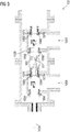
- FIG 3 illustrates a sectional elevation view of a valve arrangement 100 having a pair of double seated valve arrangements 100A and 100B connected in series, according to an embodiment of the present invention.
- the double seated valve arrangements 100A and 100B each are constructed as disclosed in the detailed description of FIG 1 and are connected in cascade, via a cascading member 301.
- a spindle spring 302 connects each of the moveable members 102A and 102B of the double seated valve arrangements 100A and 100B respectively.
- the valve seats 106A and 106B for each double seated valve arrangement 100A and 100B comprise an elastic member 107A and 107B biasable by the respective valve seats 106A and 106B.
- the cascading member 301 allows the double seated valve arrangements 100A and 100B to attain open and closed positions sequentially.
- a sequential opening and closing of the double seated valve arrangements 100A and 100B enables control of multiple load points in a steam turbine.
- the double seated valve arrangements 100A and 100B both are in their closed positions respectively as shown in FIG 3 .
- the moveable member 102A retracts in a direction away from the valve seats 105A and 106A, to a first predefined position due to which the double seated valve arrangement 100A attains an open position keeping the double seated valve arrangement 100B in the closed position.
- the moveable member 102A retracts further to a second predefined position thereby, displacing the moveable member 102B in a direction away from the valve seats 105B and 106B due to which the double seated valve arrangement 100B also attains an open position.
- the moveable member 102A moves axially forward to the first predefined position.
- the spindle spring 302 pushes the moveable member 102B so that the double seated valve arrangement 100B attains a closed position maintaining the double seated valve arrangement 100A in its open position.
- the moveable member 102A further moves axially forward to its initial position such that the double seated valve arrangement 100A also attains a closed position.
- Such a cascaded arrangement provides flexibility of design of the valve arrangement 100 and enables operation of multiple double seated valve arrangements 100A and 100B.
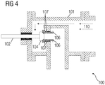
- FIG 4 illustrates a sectional elevation view of a single seated valve arrangement 100 as an embodiment of the valve arrangement according to the present invention.
- the single seated valve arrangement 100 comprises a housing 101, a moveable member 102 displaceable inside the housing 101, one valve head 104 positioned on the moveable member 102 and displaceable between a closed position when the valve head 104 is bearing against a valve seat 106 positioned within the housing 101, and an open position when the valve head 104 is axially cleared from the valve seat 106.
- the single seated valve arrangement 100 also includes an elastic member 107 at least east partially bearing against the housing 101 and biasable by the valve seat 106 in the closed position. The elastic member 107 establishes a secure contact between the valve seat 106 and the valve head 104 in the closed position, thereby, precluding uncontrolled flow of steam into the single seated valve arrangement 100, in a direction shown by the flow arrows 110.
Landscapes
- Engineering & Computer Science (AREA)
- General Engineering & Computer Science (AREA)
- Mechanical Engineering (AREA)
- Lift Valve (AREA)
Abstract
Description
- The present invention relates to a valve arrangement for fluid power equipment, such as, a steam turbine. More particularly the present invention relates to a leak-free valve arrangement for fluid power equipment that controls flow of the fluid, such as, steam into the steam turbine.
- Fluid power equipment, such as, steam turbines employed in power plants, for example, thermoelectric power plants, nuclear power plants, or the like, typically employ valve arrangements, in order to regulate flow of steam according to load changes or to stop the flow of steam altogether. Such valve arrangements typically constitute single seated valve arrangements and double seated valve arrangements. A single seated valve arrangement, typically, employs one or more actuators and these are required to be operated at high pressures for circulating pressurized fluid such as oil through the actuators. Moreover, the single seated valve arrangement involves complex piping design and is therefore, not only cumbersome in construction but also a costly arrangement.
- A double seated valve arrangement typically supports regulation of large volumes of fluid at a comparatively lower actuating force than the single seated valve arrangement. The double seated valve arrangement conventionally involves a pair of valve discs mutually separated from one another by a predefined distance, and designed to rest against a pair of valve seats during shut-off operation. However, in practicality manufacturing of a valve arrangement typically fails to achieve the precision desired, due to which positioning of valve seats within a valve arrangement is such that the valve discs fail to simultaneously rest on both the valve seats. Moreover, the valve discs fail to completely rest against the valve seats, thereby failing to provide a secure sealing at at least one of the valve seats, which further results in an unwanted leakage of the steam leading to an uncontrolled steam turbine operation. Therefore, despite of the advantages that a double seated valve arrangement poses over a single seated valve arrangement, the double seated valve arrangement remains largely unused due to non leak-free operation leading to failure of compliance with certain industry standards, for example, standards set by the American Petroleum Institute for steam turbines.
- Therefore, it is an object of the present invention to provide a valve arrangement to be employed, for example, in a fluid power equipment of the aforementioned kind, wherein the valve arrangement is simple in design, is cost effective, and ensures leak-free operation within the fluid power equipment.
- The valve arrangement disclosed in the present invention achieves the aforementioned object, in that the valve arrangement comprises an elastic member biasable by the valve seats for secure closing of the valve discs bearing against the valve seats.
- According to the present invention, a valve arrangement is provided. According to a preferred embodiment of the present invention, the valve arrangement is provided for fluid power equipment to control flow of fluid into the fluid power equipment. According to this preferred embodiment, the valve arrangement is positioned such that it is aligned to be in direction of the flow of the fluid. As used herein, "fluid power equipment" refers to turbomachinery, for example, a steam turbine.
- The valve arrangement disclosed herein, includes a housing. As used herein, the term "housing" refers to a valve chest unit enclosing a moveable member, at least one valve head, at least one valve seat, and an elastic member, of the valve arrangement. According to a preferred embodiment of the present invention, the housing is operably connected to a control mechanism of the turbomachinery, for operation of the valve arrangement, such that an outlet port of the housing is in connection with an inlet casing of a steam turbine and an inlet port of the housing is in connection with a steam inlet pipe of the steam turbine. The moveable member of the valve arrangement is displaceable inside the housing. The moveable member includes a spindle that axially reciprocates back and forth inside the housing, due to an actuating mechanism operably connected to the spindle. At least one valve head is positioned on the moveable member. The valve head is positioned axially orthogonal to the moveable member. At least one valve seat is positioned within the housing, for example, bearing against one or more inner surfaces of the housing. The valve head is displaceable between a closed position and an open position. As used herein, "closed position" refers to a position when the valve head is bearing against the valve seat. The closed position indicates a shut-off operation of the valve arrangement, wherein, fluid passing through the valve arrangement is completely stopped. As used herein, "open position" refers to a position when valve head axially clears from the valve seat, that is, displaces away from the valve seat thereby, allowing fluid to flow through the valve arrangement.
- The elastic member of the valve arrangement, is positioned within the housing such that the elastic member, at least partially, bears against the housing, for example, one or more inner surfaces of the housing. The elastic member is biasable by the valve seat, in the closed position. According to a preferred embodiment of the present invention, the valve seat is slidably attached to the housing, such that the valve seat is laterally displaceable towards the valve head due to the elastic member. The housing acts as a counter bearing for biasing the elastic member. In the closed position of the valve arrangement, the moveable member is actuated and the displaceable valve head moves towards the valve seat thereby establishing contact with the valve seat and biasing, that is, compressing the elastic member positioned between the valve seat and the housing. The biased elastic member resists this compression by exerting an opposing force on the valve seat and pushing the valve seat away from the housing, towards the valve head. The elastic member, thus, establishes a secure contact between the valve seat and the valve head in the closed position of the valve arrangement. The elastic member is selected from a group consisting of linear springs and nonlinear springs. The selection of elastic member is based on one or more parameters associated with the valve arrangement, for example, a pressure of fluid passing through the valve arrangement, an amount of force exerted by the valve head due to the actuating mechanism of the moveable member, physical dimensions of the housing, physical dimensions of the valve seat, etc. Advantageously, the elastic member comprises one or more disc springs which are easily available and are suited for majority of applications that require a high force to be exerted on a minor deflection of the spring.
- According to a preferred embodiment of the present invention, the valve arrangement is a double seated valve arrangement comprising two valve heads and two valve seats. The valve heads are connected via a flexible member allowing each of the valve heads to axially align with the valve seats in the closed position of the valve arrangement. In this preferred embodiment, the elastic member, at least partially, bears against the housing and is biasable by one of the valve seats, when in the closed position. The elastic member is positioned proximal to one of these valve seats. Advantageously, one of the valve seats, that is, the one which is biasing the elastic member, is configured to have smaller physical dimensions than the other valve seat. This facilitates an increase in design flexibility and provides ease of assembly of the valve arrangement. Advantageously, the smaller valve seat is configured to slidably attach to the housing for establishing secure contact with the valve head in the closed position of the valve arrangement. According to another embodiment of the present invention, multiple valve arrangements, for example, double seated valve arrangements as disclosed herein, are connected in a cascade, via a cascading member and wherein one of the valve seats for each valve arrangement, comprises an elastic member biasable by the respective valve seats. The cascading member allows each of the valve arrangements to sequentially attain an open position and a closed position. Advantageously, the sequential operation of the cascaded valve arrangements enables control of multiple load points in a turbomachinery.
- The above-mentioned and other features of the invention will now be addressed with reference to the accompanying drawings of the present invention. The illustrated embodiments are intended to illustrate, but not limit the invention.
- The present invention is further described hereinafter with reference to illustrated embodiments shown in the accompanying drawings, in which:
- FIG 1
- illustrates a sectional elevation view of a double seated valve arrangement for a steam turbine as an embodiment of the valve arrangement according to the present invention.
- FIGS 2A-2B
- illustrate sectional elevation views of the double seated valve arrangement shown in
FIG 1 in an open position and a closed position of operation, according to an embodiment of the present invention. - FIG 3
- illustrates a sectional elevation view of a valve arrangement having a pair of double seated valve arrangements connected in series, according to an embodiment of the present invention.
- FIG 4
- illustrates a sectional elevation view of a single seated valve arrangement as an embodiment of the valve arrangement according to the present invention.
- Various embodiments are described with reference to the drawings, wherein like reference numerals are used to refer to like elements throughout. In the following description, for the purpose of explanation, numerous specific details are set forth in order to provide thorough understanding of one or more embodiments. It may be evident that such embodiments may be practiced without these specific details.
-
FIG 1 illustrates a sectional elevation view of a double seatedvalve arrangement 100 for a steam turbine (not shown) having steam flowing therein in a direction shown by theflow arrows 110, as an embodiment of the valve arrangement according to the present invention. As illustrated inFIG 1 , the double seatedvalve arrangement 100 comprises ahousing 101 in connection withflanges 111 of an actuating mechanism (not shown), amoveable member 102,valve heads flexible member 108,valve seats elastic members 107 biasable by thevalve seat 106. Themoveable member 102 is displaceable inside thehousing 101 by the actuating mechanism, between a closed position and an open position of the double seatedvalve arrangement 100 illustrated inFIGS 2A-2B . Thevalve seat 106 is slidably attached to thehousing 101, via a sealingmember 109 such that thevalve seat 106 is laterally displaceable in a direction towards or away from thevalve head 104 based on biasing and un-biasing of theelastic member 107. -
FIGS 2A-2B illustrate sectional elevation views of the double seatedvalve arrangement 100 shown inFIG 1 in an open position and a closed position of operation, according to an embodiment of the present invention. In the closed position, the valve heads 103 and 104 are bearing against the valve seats 105 and 106 respectively. In the open position, the valve heads 103 and 104 are axially cleared from the valve seats 105 and 106. Assuming, a default state of operation of the double seatedvalve arrangement 100 is the closed position, as shown inFIG 2A , where theelastic member 107 is in a biased state, that is, a compressed state. In the closed position of the double seatedvalve arrangement 100, thevalve head 103 bears against thevalve seat 105 and thevalve head 104 bears against thevalve seat 106 and biases theelastic member 107 to a compressed state. In this biased state, thevalve seat 106 initially moves towards thehousing 101 as a result of displacement of themoveable member 102, however, theelastic member 107 exerts an opposing force to resist movement of thevalve seat 106 towards thehousing 101, thereby, ensuring a secure connection of thevalve seat 106 with thevalve head 104.FIG 2B illustrates an open position of the double seatedvalve arrangement 100, wherein themoveable member 102 axially retracts thereby, clearing the valve heads 103 and 104 off the valve seats 105 and 106 respectively, and returning theelastic member 107 to its unbiased, that is, an uncompressed state. In this open position thevalve seat 106 slides, along the sealingmember 109, further away from thehousing 101, as theelastic member 107 becomes completely uncompressed. Astopper member 112 precludes thevalve seat 106 from sliding off thehousing 101. -
FIG 3 illustrates a sectional elevation view of avalve arrangement 100 having a pair of doubleseated valve arrangements seated valve arrangements FIG 1 and are connected in cascade, via a cascadingmember 301. Aspindle spring 302 connects each of themoveable members seated valve arrangements valve arrangement elastic member respective valve seats - The cascading
member 301 allows the doubleseated valve arrangements seated valve arrangements seated valve arrangements FIG 3 . In a sequential opening operation, themoveable member 102A retracts in a direction away from thevalve seats valve arrangement 100A attains an open position keeping the double seatedvalve arrangement 100B in the closed position. Further, themoveable member 102A retracts further to a second predefined position thereby, displacing themoveable member 102B in a direction away from the valve seats 105B and 106B due to which the double seatedvalve arrangement 100B also attains an open position. Similarly, in a sequential closing operation, themoveable member 102A moves axially forward to the first predefined position. Thespindle spring 302 pushes themoveable member 102B so that the double seatedvalve arrangement 100B attains a closed position maintaining the double seatedvalve arrangement 100A in its open position. Themoveable member 102A further moves axially forward to its initial position such that the double seatedvalve arrangement 100A also attains a closed position. Such a cascaded arrangement provides flexibility of design of thevalve arrangement 100 and enables operation of multiple doubleseated valve arrangements -
FIG 4 illustrates a sectional elevation view of a single seatedvalve arrangement 100 as an embodiment of the valve arrangement according to the present invention. The single seatedvalve arrangement 100 comprises ahousing 101, amoveable member 102 displaceable inside thehousing 101, onevalve head 104 positioned on themoveable member 102 and displaceable between a closed position when thevalve head 104 is bearing against avalve seat 106 positioned within thehousing 101, and an open position when thevalve head 104 is axially cleared from thevalve seat 106. The single seatedvalve arrangement 100 also includes anelastic member 107 at least east partially bearing against thehousing 101 and biasable by thevalve seat 106 in the closed position. Theelastic member 107 establishes a secure contact between thevalve seat 106 and thevalve head 104 in the closed position, thereby, precluding uncontrolled flow of steam into the single seatedvalve arrangement 100, in a direction shown by theflow arrows 110. - The foregoing examples have been provided merely for the purpose of explanation and are in no way to be construed as limiting of the present invention disclosed herein. While the invention has been described with reference to various embodiments, it is understood that the words, which have been used herein, are words of description and illustration, rather than words of limitation. Further, although the invention has been described herein with reference to particular means, materials, and embodiments, the invention is not intended to be limited to the particulars disclosed herein; rather, the invention extends to all functionally equivalent structures, methods and uses, such as are within the scope of the appended claims. Those skilled in the art, having the benefit of the teachings of this specification, may affect numerous modifications thereto and changes may be made without departing from the scope and spirit of the invention in its aspects.
Claims (10)
- A valve arrangement (100) having:- a housing (101);- a moveable member (102) displaceable inside the housing (101);- at least one valve head (103, 104) positioned on the moveable member (102) and displaceable between a closed position when said at least one valve head (103, 104) is bearing against at least one valve seat (105, 106) positioned within the housing (101), and an open position when said at least one valve head (103, 104) is axially cleared from said at least one valve seat (105, 106);characterized by:- an elastic member (107), at least partially, bearing against the housing (101) and biasable by said at least one valve seat (105, 106) in the closed position, wherein said elastic member (107) establishes a secure contact between said at least one valve seat (105, 106) and said at least one valve head (103, 104) in the closed position.
- The valve arrangement (100) according to claim 1, wherein said at least one valve seat (105, 106) is slidably attached to said housing (101), such that said at least one valve seat (105, 106) is laterally displaceable towards said at least one valve head (103, 104) due to the elastic member (107).
- The valve arrangement (100) according to any one of the previous claims, wherein the elastic member (107) is selected from a group consisting of linear springs and non linear springs.
- The valve arrangement (100) according to claim 3, wherein the elastic member (107) comprises one or more disc springs.
- The valve arrangement (100) according to any one of the previous claims 1-3, is a double seated valve arrangement comprising two valve heads (103, 104) and two valve seats (105, 106).
- The valve arrangement (100) according to claim 5, characterized by an elastic member (107), at least partially, bearing against the housing (101) and biasable by one of the two valve seats (105 or 106), when in the closed position.
- The valve arrangement (100) according to any one of the claims 5 and 6, wherein the valve heads (103, 104) are connected via a flexible member (108) such that each of the valve heads (103, 104) axially aligns with the valve seats (105, 106) in the closed position.
- The valve arrangement (100) according to any one of the claims 5, 6 and 7, wherein one of the valve seats (105 or 106) is configured to have smaller physical dimensions than the other valve seat (105 or 106).
- A fluid power equipment comprising a valve arrangement (100) of the claims 1-8 for controlling flow of fluid into the fluid power equipment, wherein the valve arrangement (100) is arranged in direction of the fluid.
- The fluid power equipment according to claim 9 is a steam turbine.
Priority Applications (2)
| Application Number | Priority Date | Filing Date | Title |
|---|---|---|---|
| EP17182296.8A EP3431840B1 (en) | 2017-07-20 | 2017-07-20 | Valve arrangement for fluid power equipment |
| PL17182296T PL3431840T3 (en) | 2017-07-20 | 2017-07-20 | Valve arrangement for fluid power equipment |
Applications Claiming Priority (1)
| Application Number | Priority Date | Filing Date | Title |
|---|---|---|---|
| EP17182296.8A EP3431840B1 (en) | 2017-07-20 | 2017-07-20 | Valve arrangement for fluid power equipment |
Publications (2)
| Publication Number | Publication Date |
|---|---|
| EP3431840A1 true EP3431840A1 (en) | 2019-01-23 |
| EP3431840B1 EP3431840B1 (en) | 2020-09-23 |
Family
ID=59383461
Family Applications (1)
| Application Number | Title | Priority Date | Filing Date |
|---|---|---|---|
| EP17182296.8A Active EP3431840B1 (en) | 2017-07-20 | 2017-07-20 | Valve arrangement for fluid power equipment |
Country Status (2)
| Country | Link |
|---|---|
| EP (1) | EP3431840B1 (en) |
| PL (1) | PL3431840T3 (en) |
Cited By (2)
| Publication number | Priority date | Publication date | Assignee | Title |
|---|---|---|---|---|
| EP3742028A1 (en) * | 2019-05-21 | 2020-11-25 | Siemens Aktiengesellschaft | Protection against rotation for valve spindles |
| EP4187133A1 (en) * | 2021-11-24 | 2023-05-31 | Leinemann GmbH & Co. KG | Valve |
Citations (4)
| Publication number | Priority date | Publication date | Assignee | Title |
|---|---|---|---|---|
| DE835448C (en) * | 1943-04-29 | 1952-03-31 | Gustav Friedrich Gerdts | Valve seat arrangement for drain valves from tank wagons and similar containers |
| US3857408A (en) * | 1973-10-23 | 1974-12-31 | Acf Ind Inc | Seat and sealing means for clapper-type check valve |
| US5483991A (en) * | 1993-05-12 | 1996-01-16 | Societe Nationale D'etude Et De Construction De Moteurs D'aviation "S.N.E.C.M.A." | Valve with self-centering seat |
| JP2002188732A (en) * | 2000-12-20 | 2002-07-05 | Ckd Corp | Fluid control valve |
Family Cites Families (3)
| Publication number | Priority date | Publication date | Assignee | Title |
|---|---|---|---|---|
| US1076446A (en) * | 1912-05-04 | 1913-10-21 | Gen Electric | Steam-regulator for turbines. |
| JPS589307B2 (en) * | 1978-08-23 | 1983-02-19 | 株式会社日立製作所 | Proportional solenoid valve |
| JP2007524050A (en) * | 2004-02-27 | 2007-08-23 | デーナ、カナダ、コーパレイシャン | Leakage resistant solenoid valve |
-
2017
- 2017-07-20 PL PL17182296T patent/PL3431840T3/en unknown
- 2017-07-20 EP EP17182296.8A patent/EP3431840B1/en active Active
Patent Citations (4)
| Publication number | Priority date | Publication date | Assignee | Title |
|---|---|---|---|---|
| DE835448C (en) * | 1943-04-29 | 1952-03-31 | Gustav Friedrich Gerdts | Valve seat arrangement for drain valves from tank wagons and similar containers |
| US3857408A (en) * | 1973-10-23 | 1974-12-31 | Acf Ind Inc | Seat and sealing means for clapper-type check valve |
| US5483991A (en) * | 1993-05-12 | 1996-01-16 | Societe Nationale D'etude Et De Construction De Moteurs D'aviation "S.N.E.C.M.A." | Valve with self-centering seat |
| JP2002188732A (en) * | 2000-12-20 | 2002-07-05 | Ckd Corp | Fluid control valve |
Cited By (3)
| Publication number | Priority date | Publication date | Assignee | Title |
|---|---|---|---|---|
| EP3742028A1 (en) * | 2019-05-21 | 2020-11-25 | Siemens Aktiengesellschaft | Protection against rotation for valve spindles |
| EP4187133A1 (en) * | 2021-11-24 | 2023-05-31 | Leinemann GmbH & Co. KG | Valve |
| US11953107B2 (en) | 2021-11-24 | 2024-04-09 | Leinemann Gmbh & Co. Kg | Valve |
Also Published As
| Publication number | Publication date |
|---|---|
| EP3431840B1 (en) | 2020-09-23 |
| PL3431840T3 (en) | 2021-03-08 |
Similar Documents
| Publication | Publication Date | Title |
|---|---|---|
| BRPI0808080A2 (en) | SPRING SET, AND, DIAPHRAGM ACTUATOR | |
| EP2519752B1 (en) | Apparatus to increase a force of an actuator having an override apparatus | |
| EP2391842B1 (en) | Actuator having an override apparatus | |
| US11719349B2 (en) | Axial three-way modulating valve | |
| US9404513B2 (en) | Servo valve | |
| EP3431840B1 (en) | Valve arrangement for fluid power equipment | |
| EP3204671A1 (en) | Balanced double seated globe valve with flexible plug | |
| US10711902B2 (en) | Flow dividing valve | |
| EP3267278B1 (en) | Pressure balanced thermal actuator | |
| CN109555863A (en) | It adjusts for the overtravel in double furcation plugs used in valve module | |
| US20220390024A1 (en) | Improvements in, or relating to, sliding spool valves, and methods therefor | |
| DE102014000469B4 (en) | screw compressors | |
| NO20150031A1 (en) | Axial fluid valves having linear actuators. | |
| EP3009619B1 (en) | Gas exchange valve actuator for axial displacement of a gas exchange valve of a combustion engine | |
| DE19540816A1 (en) | Reversing valve and heater with a reversing valve | |
| EP3875812A1 (en) | Double seated valve arrangement for fluid power equipment | |
| RU2364779C2 (en) | Safety valve | |
| EP2385283A1 (en) | Pneumatic valve | |
| DE102014216263B3 (en) | Steam valve device | |
| DE102024209478A1 (en) | oil pump | |
| EP1953431A2 (en) | A shuttle valve assembly | |
| RU2014536C1 (en) | Gate valve | |
| EP1754916A1 (en) | Valve with piezoelectric element | |
| WO2025256731A1 (en) | Heat pump assembly with switching valve | |
| Bhasin | Actuator Selection |
Legal Events
| Date | Code | Title | Description |
|---|---|---|---|
| PUAI | Public reference made under article 153(3) epc to a published international application that has entered the european phase |
Free format text: ORIGINAL CODE: 0009012 |
|
| STAA | Information on the status of an ep patent application or granted ep patent |
Free format text: STATUS: THE APPLICATION HAS BEEN PUBLISHED |
|
| AK | Designated contracting states |
Kind code of ref document: A1 Designated state(s): AL AT BE BG CH CY CZ DE DK EE ES FI FR GB GR HR HU IE IS IT LI LT LU LV MC MK MT NL NO PL PT RO RS SE SI SK SM TR |
|
| AX | Request for extension of the european patent |
Extension state: BA ME |
|
| STAA | Information on the status of an ep patent application or granted ep patent |
Free format text: STATUS: REQUEST FOR EXAMINATION WAS MADE |
|
| 17P | Request for examination filed |
Effective date: 20190704 |
|
| RBV | Designated contracting states (corrected) |
Designated state(s): AL AT BE BG CH CY CZ DE DK EE ES FI FR GB GR HR HU IE IS IT LI LT LU LV MC MK MT NL NO PL PT RO RS SE SI SK SM TR |
|
| STAA | Information on the status of an ep patent application or granted ep patent |
Free format text: STATUS: EXAMINATION IS IN PROGRESS |
|
| 17Q | First examination report despatched |
Effective date: 20191022 |
|
| RIC1 | Information provided on ipc code assigned before grant |
Ipc: F01D 17/14 20060101ALI20200316BHEP Ipc: F16K 1/42 20060101AFI20200316BHEP Ipc: F16K 1/44 20060101ALI20200316BHEP Ipc: F16K 11/16 20060101ALI20200316BHEP |
|
| GRAP | Despatch of communication of intention to grant a patent |
Free format text: ORIGINAL CODE: EPIDOSNIGR1 |
|
| STAA | Information on the status of an ep patent application or granted ep patent |
Free format text: STATUS: GRANT OF PATENT IS INTENDED |
|
| INTG | Intention to grant announced |
Effective date: 20200511 |
|
| GRAS | Grant fee paid |
Free format text: ORIGINAL CODE: EPIDOSNIGR3 |
|
| GRAA | (expected) grant |
Free format text: ORIGINAL CODE: 0009210 |
|
| STAA | Information on the status of an ep patent application or granted ep patent |
Free format text: STATUS: THE PATENT HAS BEEN GRANTED |
|
| AK | Designated contracting states |
Kind code of ref document: B1 Designated state(s): AL AT BE BG CH CY CZ DE DK EE ES FI FR GB GR HR HU IE IS IT LI LT LU LV MC MK MT NL NO PL PT RO RS SE SI SK SM TR |
|
| REG | Reference to a national code |
Ref country code: GB Ref legal event code: FG4D |
|
| REG | Reference to a national code |
Ref country code: CH Ref legal event code: EP |
|
| REG | Reference to a national code |
Ref country code: DE Ref legal event code: R096 Ref document number: 602017024017 Country of ref document: DE |
|
| REG | Reference to a national code |
Ref country code: IE Ref legal event code: FG4D |
|
| REG | Reference to a national code |
Ref country code: AT Ref legal event code: REF Ref document number: 1316708 Country of ref document: AT Kind code of ref document: T Effective date: 20201015 |
|
| REG | Reference to a national code |
Ref country code: DE Ref legal event code: R081 Ref document number: 602017024017 Country of ref document: DE Owner name: SIEMENS ENERGY GLOBAL GMBH & CO. KG, DE Free format text: FORMER OWNER: SIEMENS AKTIENGESELLSCHAFT, 80333 MUENCHEN, DE |
|
| RAP2 | Party data changed (patent owner data changed or rights of a patent transferred) |
Owner name: SIEMENS ENERGY GLOBAL GMBH & CO. KG |
|
| PG25 | Lapsed in a contracting state [announced via postgrant information from national office to epo] |
Ref country code: FI Free format text: LAPSE BECAUSE OF FAILURE TO SUBMIT A TRANSLATION OF THE DESCRIPTION OR TO PAY THE FEE WITHIN THE PRESCRIBED TIME-LIMIT Effective date: 20200923 Ref country code: HR Free format text: LAPSE BECAUSE OF FAILURE TO SUBMIT A TRANSLATION OF THE DESCRIPTION OR TO PAY THE FEE WITHIN THE PRESCRIBED TIME-LIMIT Effective date: 20200923 Ref country code: SE Free format text: LAPSE BECAUSE OF FAILURE TO SUBMIT A TRANSLATION OF THE DESCRIPTION OR TO PAY THE FEE WITHIN THE PRESCRIBED TIME-LIMIT Effective date: 20200923 Ref country code: NO Free format text: LAPSE BECAUSE OF FAILURE TO SUBMIT A TRANSLATION OF THE DESCRIPTION OR TO PAY THE FEE WITHIN THE PRESCRIBED TIME-LIMIT Effective date: 20201223 Ref country code: GR Free format text: LAPSE BECAUSE OF FAILURE TO SUBMIT A TRANSLATION OF THE DESCRIPTION OR TO PAY THE FEE WITHIN THE PRESCRIBED TIME-LIMIT Effective date: 20201224 Ref country code: BG Free format text: LAPSE BECAUSE OF FAILURE TO SUBMIT A TRANSLATION OF THE DESCRIPTION OR TO PAY THE FEE WITHIN THE PRESCRIBED TIME-LIMIT Effective date: 20201223 |
|
| REG | Reference to a national code |
Ref country code: AT Ref legal event code: MK05 Ref document number: 1316708 Country of ref document: AT Kind code of ref document: T Effective date: 20200923 |
|
| PG25 | Lapsed in a contracting state [announced via postgrant information from national office to epo] |
Ref country code: LV Free format text: LAPSE BECAUSE OF FAILURE TO SUBMIT A TRANSLATION OF THE DESCRIPTION OR TO PAY THE FEE WITHIN THE PRESCRIBED TIME-LIMIT Effective date: 20200923 Ref country code: RS Free format text: LAPSE BECAUSE OF FAILURE TO SUBMIT A TRANSLATION OF THE DESCRIPTION OR TO PAY THE FEE WITHIN THE PRESCRIBED TIME-LIMIT Effective date: 20200923 |
|
| REG | Reference to a national code |
Ref country code: NL Ref legal event code: MP Effective date: 20200923 |
|
| REG | Reference to a national code |
Ref country code: LT Ref legal event code: MG4D |
|
| PG25 | Lapsed in a contracting state [announced via postgrant information from national office to epo] |
Ref country code: LT Free format text: LAPSE BECAUSE OF FAILURE TO SUBMIT A TRANSLATION OF THE DESCRIPTION OR TO PAY THE FEE WITHIN THE PRESCRIBED TIME-LIMIT Effective date: 20200923 Ref country code: RO Free format text: LAPSE BECAUSE OF FAILURE TO SUBMIT A TRANSLATION OF THE DESCRIPTION OR TO PAY THE FEE WITHIN THE PRESCRIBED TIME-LIMIT Effective date: 20200923 Ref country code: PT Free format text: LAPSE BECAUSE OF FAILURE TO SUBMIT A TRANSLATION OF THE DESCRIPTION OR TO PAY THE FEE WITHIN THE PRESCRIBED TIME-LIMIT Effective date: 20210125 Ref country code: SM Free format text: LAPSE BECAUSE OF FAILURE TO SUBMIT A TRANSLATION OF THE DESCRIPTION OR TO PAY THE FEE WITHIN THE PRESCRIBED TIME-LIMIT Effective date: 20200923 Ref country code: EE Free format text: LAPSE BECAUSE OF FAILURE TO SUBMIT A TRANSLATION OF THE DESCRIPTION OR TO PAY THE FEE WITHIN THE PRESCRIBED TIME-LIMIT Effective date: 20200923 |
|
| PG25 | Lapsed in a contracting state [announced via postgrant information from national office to epo] |
Ref country code: ES Free format text: LAPSE BECAUSE OF FAILURE TO SUBMIT A TRANSLATION OF THE DESCRIPTION OR TO PAY THE FEE WITHIN THE PRESCRIBED TIME-LIMIT Effective date: 20200923 Ref country code: AT Free format text: LAPSE BECAUSE OF FAILURE TO SUBMIT A TRANSLATION OF THE DESCRIPTION OR TO PAY THE FEE WITHIN THE PRESCRIBED TIME-LIMIT Effective date: 20200923 Ref country code: AL Free format text: LAPSE BECAUSE OF FAILURE TO SUBMIT A TRANSLATION OF THE DESCRIPTION OR TO PAY THE FEE WITHIN THE PRESCRIBED TIME-LIMIT Effective date: 20200923 Ref country code: IS Free format text: LAPSE BECAUSE OF FAILURE TO SUBMIT A TRANSLATION OF THE DESCRIPTION OR TO PAY THE FEE WITHIN THE PRESCRIBED TIME-LIMIT Effective date: 20210123 |
|
| REG | Reference to a national code |
Ref country code: DE Ref legal event code: R097 Ref document number: 602017024017 Country of ref document: DE |
|
| PG25 | Lapsed in a contracting state [announced via postgrant information from national office to epo] |
Ref country code: SK Free format text: LAPSE BECAUSE OF FAILURE TO SUBMIT A TRANSLATION OF THE DESCRIPTION OR TO PAY THE FEE WITHIN THE PRESCRIBED TIME-LIMIT Effective date: 20200923 |
|
| PLBE | No opposition filed within time limit |
Free format text: ORIGINAL CODE: 0009261 |
|
| STAA | Information on the status of an ep patent application or granted ep patent |
Free format text: STATUS: NO OPPOSITION FILED WITHIN TIME LIMIT |
|
| PG25 | Lapsed in a contracting state [announced via postgrant information from national office to epo] |
Ref country code: DK Free format text: LAPSE BECAUSE OF FAILURE TO SUBMIT A TRANSLATION OF THE DESCRIPTION OR TO PAY THE FEE WITHIN THE PRESCRIBED TIME-LIMIT Effective date: 20200923 Ref country code: SI Free format text: LAPSE BECAUSE OF FAILURE TO SUBMIT A TRANSLATION OF THE DESCRIPTION OR TO PAY THE FEE WITHIN THE PRESCRIBED TIME-LIMIT Effective date: 20200923 |
|
| 26N | No opposition filed |
Effective date: 20210624 |
|
| PG25 | Lapsed in a contracting state [announced via postgrant information from national office to epo] |
Ref country code: IT Free format text: LAPSE BECAUSE OF FAILURE TO SUBMIT A TRANSLATION OF THE DESCRIPTION OR TO PAY THE FEE WITHIN THE PRESCRIBED TIME-LIMIT Effective date: 20200923 |
|
| REG | Reference to a national code |
Ref country code: CH Ref legal event code: PL |
|
| GBPC | Gb: european patent ceased through non-payment of renewal fee |
Effective date: 20210720 |
|
| PG25 | Lapsed in a contracting state [announced via postgrant information from national office to epo] |
Ref country code: MC Free format text: LAPSE BECAUSE OF FAILURE TO SUBMIT A TRANSLATION OF THE DESCRIPTION OR TO PAY THE FEE WITHIN THE PRESCRIBED TIME-LIMIT Effective date: 20200923 |
|
| REG | Reference to a national code |
Ref country code: BE Ref legal event code: MM Effective date: 20210731 |
|
| PG25 | Lapsed in a contracting state [announced via postgrant information from national office to epo] |
Ref country code: LI Free format text: LAPSE BECAUSE OF NON-PAYMENT OF DUE FEES Effective date: 20210731 Ref country code: GB Free format text: LAPSE BECAUSE OF NON-PAYMENT OF DUE FEES Effective date: 20210720 Ref country code: CH Free format text: LAPSE BECAUSE OF NON-PAYMENT OF DUE FEES Effective date: 20210731 |
|
| PG25 | Lapsed in a contracting state [announced via postgrant information from national office to epo] |
Ref country code: LU Free format text: LAPSE BECAUSE OF NON-PAYMENT OF DUE FEES Effective date: 20210720 Ref country code: FR Free format text: LAPSE BECAUSE OF NON-PAYMENT OF DUE FEES Effective date: 20210731 |
|
| PG25 | Lapsed in a contracting state [announced via postgrant information from national office to epo] |
Ref country code: IE Free format text: LAPSE BECAUSE OF NON-PAYMENT OF DUE FEES Effective date: 20210720 Ref country code: BE Free format text: LAPSE BECAUSE OF NON-PAYMENT OF DUE FEES Effective date: 20210731 |
|
| PG25 | Lapsed in a contracting state [announced via postgrant information from national office to epo] |
Ref country code: NL Free format text: LAPSE BECAUSE OF NON-PAYMENT OF DUE FEES Effective date: 20200923 Ref country code: CY Free format text: LAPSE BECAUSE OF FAILURE TO SUBMIT A TRANSLATION OF THE DESCRIPTION OR TO PAY THE FEE WITHIN THE PRESCRIBED TIME-LIMIT Effective date: 20200923 |
|
| PG25 | Lapsed in a contracting state [announced via postgrant information from national office to epo] |
Ref country code: HU Free format text: LAPSE BECAUSE OF FAILURE TO SUBMIT A TRANSLATION OF THE DESCRIPTION OR TO PAY THE FEE WITHIN THE PRESCRIBED TIME-LIMIT; INVALID AB INITIO Effective date: 20170720 |
|
| PG25 | Lapsed in a contracting state [announced via postgrant information from national office to epo] |
Ref country code: MK Free format text: LAPSE BECAUSE OF FAILURE TO SUBMIT A TRANSLATION OF THE DESCRIPTION OR TO PAY THE FEE WITHIN THE PRESCRIBED TIME-LIMIT Effective date: 20200923 |
|
| PG25 | Lapsed in a contracting state [announced via postgrant information from national office to epo] |
Ref country code: TR Free format text: LAPSE BECAUSE OF FAILURE TO SUBMIT A TRANSLATION OF THE DESCRIPTION OR TO PAY THE FEE WITHIN THE PRESCRIBED TIME-LIMIT Effective date: 20200923 |
|
| PG25 | Lapsed in a contracting state [announced via postgrant information from national office to epo] |
Ref country code: MT Free format text: LAPSE BECAUSE OF FAILURE TO SUBMIT A TRANSLATION OF THE DESCRIPTION OR TO PAY THE FEE WITHIN THE PRESCRIBED TIME-LIMIT Effective date: 20200923 |
|
| PGFP | Annual fee paid to national office [announced via postgrant information from national office to epo] |
Ref country code: PL Payment date: 20250626 Year of fee payment: 9 |
|
| PGFP | Annual fee paid to national office [announced via postgrant information from national office to epo] |
Ref country code: DE Payment date: 20250728 Year of fee payment: 9 |
|
| PGFP | Annual fee paid to national office [announced via postgrant information from national office to epo] |
Ref country code: CZ Payment date: 20250707 Year of fee payment: 9 |