EP3431834B1 - Rotary seal - Google Patents
Rotary seal Download PDFInfo
- Publication number
- EP3431834B1 EP3431834B1 EP18182589.4A EP18182589A EP3431834B1 EP 3431834 B1 EP3431834 B1 EP 3431834B1 EP 18182589 A EP18182589 A EP 18182589A EP 3431834 B1 EP3431834 B1 EP 3431834B1
- Authority
- EP
- European Patent Office
- Prior art keywords
- lip
- flange portion
- outward flange
- tip end
- wetting inhibitor
- Prior art date
- Legal status (The legal status is an assumption and is not a legal conclusion. Google has not performed a legal analysis and makes no representation as to the accuracy of the status listed.)
- Active
Links
Images



Classifications
-
- F—MECHANICAL ENGINEERING; LIGHTING; HEATING; WEAPONS; BLASTING
- F16—ENGINEERING ELEMENTS AND UNITS; GENERAL MEASURES FOR PRODUCING AND MAINTAINING EFFECTIVE FUNCTIONING OF MACHINES OR INSTALLATIONS; THERMAL INSULATION IN GENERAL
- F16J—PISTONS; CYLINDERS; SEALINGS
- F16J15/00—Sealings
- F16J15/16—Sealings between relatively-moving surfaces
- F16J15/32—Sealings between relatively-moving surfaces with elastic sealings, e.g. O-rings
- F16J15/3204—Sealings between relatively-moving surfaces with elastic sealings, e.g. O-rings with at least one lip
- F16J15/3232—Sealings between relatively-moving surfaces with elastic sealings, e.g. O-rings with at least one lip having two or more lips
- F16J15/3236—Sealings between relatively-moving surfaces with elastic sealings, e.g. O-rings with at least one lip having two or more lips with at least one lip for each surface, e.g. U-cup packings
-
- F—MECHANICAL ENGINEERING; LIGHTING; HEATING; WEAPONS; BLASTING
- F16—ENGINEERING ELEMENTS AND UNITS; GENERAL MEASURES FOR PRODUCING AND MAINTAINING EFFECTIVE FUNCTIONING OF MACHINES OR INSTALLATIONS; THERMAL INSULATION IN GENERAL
- F16C—SHAFTS; FLEXIBLE SHAFTS; ELEMENTS OR CRANKSHAFT MECHANISMS; ROTARY BODIES OTHER THAN GEARING ELEMENTS; BEARINGS
- F16C33/00—Parts of bearings; Special methods for making bearings or parts thereof
- F16C33/72—Sealings
- F16C33/76—Sealings of ball or roller bearings
- F16C33/78—Sealings of ball or roller bearings with a diaphragm, disc, or ring, with or without resilient members
- F16C33/7816—Details of the sealing or parts thereof, e.g. geometry, material
- F16C33/782—Details of the sealing or parts thereof, e.g. geometry, material of the sealing region
- F16C33/7823—Details of the sealing or parts thereof, e.g. geometry, material of the sealing region of sealing lips
-
- F—MECHANICAL ENGINEERING; LIGHTING; HEATING; WEAPONS; BLASTING
- F16—ENGINEERING ELEMENTS AND UNITS; GENERAL MEASURES FOR PRODUCING AND MAINTAINING EFFECTIVE FUNCTIONING OF MACHINES OR INSTALLATIONS; THERMAL INSULATION IN GENERAL
- F16C—SHAFTS; FLEXIBLE SHAFTS; ELEMENTS OR CRANKSHAFT MECHANISMS; ROTARY BODIES OTHER THAN GEARING ELEMENTS; BEARINGS
- F16C33/00—Parts of bearings; Special methods for making bearings or parts thereof
- F16C33/72—Sealings
- F16C33/76—Sealings of ball or roller bearings
- F16C33/78—Sealings of ball or roller bearings with a diaphragm, disc, or ring, with or without resilient members
- F16C33/7869—Sealings of ball or roller bearings with a diaphragm, disc, or ring, with or without resilient members mounted with a cylindrical portion to the inner surface of the outer race and having a radial portion extending inward
- F16C33/7879—Sealings of ball or roller bearings with a diaphragm, disc, or ring, with or without resilient members mounted with a cylindrical portion to the inner surface of the outer race and having a radial portion extending inward with a further sealing ring
- F16C33/7883—Sealings of ball or roller bearings with a diaphragm, disc, or ring, with or without resilient members mounted with a cylindrical portion to the inner surface of the outer race and having a radial portion extending inward with a further sealing ring mounted to the inner race and of generally L-shape, the two sealing rings defining a sealing with box-shaped cross-section
-
- F—MECHANICAL ENGINEERING; LIGHTING; HEATING; WEAPONS; BLASTING
- F16—ENGINEERING ELEMENTS AND UNITS; GENERAL MEASURES FOR PRODUCING AND MAINTAINING EFFECTIVE FUNCTIONING OF MACHINES OR INSTALLATIONS; THERMAL INSULATION IN GENERAL
- F16J—PISTONS; CYLINDERS; SEALINGS
- F16J15/00—Sealings
- F16J15/16—Sealings between relatively-moving surfaces
- F16J15/32—Sealings between relatively-moving surfaces with elastic sealings, e.g. O-rings
- F16J15/3248—Sealings between relatively-moving surfaces with elastic sealings, e.g. O-rings provided with casings or supports
- F16J15/3252—Sealings between relatively-moving surfaces with elastic sealings, e.g. O-rings provided with casings or supports with rigid casings or supports
- F16J15/3256—Sealings between relatively-moving surfaces with elastic sealings, e.g. O-rings provided with casings or supports with rigid casings or supports comprising two casing or support elements, one attached to each surface, e.g. cartridge or cassette seals
- F16J15/3264—Sealings between relatively-moving surfaces with elastic sealings, e.g. O-rings provided with casings or supports with rigid casings or supports comprising two casing or support elements, one attached to each surface, e.g. cartridge or cassette seals the elements being separable from each other
-
- F—MECHANICAL ENGINEERING; LIGHTING; HEATING; WEAPONS; BLASTING
- F16—ENGINEERING ELEMENTS AND UNITS; GENERAL MEASURES FOR PRODUCING AND MAINTAINING EFFECTIVE FUNCTIONING OF MACHINES OR INSTALLATIONS; THERMAL INSULATION IN GENERAL
- F16J—PISTONS; CYLINDERS; SEALINGS
- F16J15/00—Sealings
- F16J15/16—Sealings between relatively-moving surfaces
- F16J15/32—Sealings between relatively-moving surfaces with elastic sealings, e.g. O-rings
- F16J15/3268—Mounting of sealing rings
-
- F—MECHANICAL ENGINEERING; LIGHTING; HEATING; WEAPONS; BLASTING
- F16—ENGINEERING ELEMENTS AND UNITS; GENERAL MEASURES FOR PRODUCING AND MAINTAINING EFFECTIVE FUNCTIONING OF MACHINES OR INSTALLATIONS; THERMAL INSULATION IN GENERAL
- F16J—PISTONS; CYLINDERS; SEALINGS
- F16J15/00—Sealings
- F16J15/16—Sealings between relatively-moving surfaces
- F16J15/32—Sealings between relatively-moving surfaces with elastic sealings, e.g. O-rings
- F16J15/3284—Sealings between relatively-moving surfaces with elastic sealings, e.g. O-rings characterised by their structure; Selection of materials
Definitions
- the present invention relates to a rotary seal for use in a horizontal rotation axis or an inclined rotation axis in a transport machine or a general machine.
- a rotary seal for use in a horizontal rotation axis or inclined rotation axis of a bearing device for supporting an automotive wheel
- a rotary seal including a slinger, a core metal, and a seal member, which are composed as follows.
- the slinger is composed of a cylindrical portion and an outward flange portion extending radially outward from an axial end of the cylindrical portion.
- the core metal is composed of a cylindrical portion and an inward flange portion extending radially inward from an axial end of the cylindrical portion.
- the seal member is composed of a base joined to the core metal and a seal lip including an axial lip in sliding contact with an axially inner surface of the outward flange portion, the seal member extending from the base (see, for example, Japanese Unexamined Patent Application Publication Nos. 62-283261 , 2001-065704 and 2008-202737 ).
- Such a rotary seal as described above is used in a state where the cylindrical portion of the slinger is attached to a radially inner member (for example, an inner ring of a bearing) and the cylindrical portion of the core metal is attached to a radially outer member (for example, an outer ring of the bearing).
- a labyrinth gap (B) is formed of a gap between a tip end of the outward flange of the slinger and a tip end of the cylindrical portion of the core metal.
- the tip end of the outward flange portion and the tip end of the cylindrical portion are formed into inclined planes (C).
- a labyrinth seal (4) is formed of a gap between a tip end of the outward flange portion of the slinger and the seal member that covers the tip end of the cylindrical portion of the core metal.
- an outer side surface (B) of the outward flange portion is retreated by a predetermined retreat amount (L) inward from an end surface (A) of the seal member that covers the tip end of the cylindrical portion.
- a second side lip (20) that is an axial lip is provided at a radially outward position of a first side lip (19) that is an axial lip in sliding contact with an axial end surface (33a) of a flange portion (33) of a slinger (31).
- a labyrinth seal (41) is formed of a gap between a tip end of the second side lip (20) and the axial end surface (33a).
- the gap between the tip end of the outward flange portion of the slinger and the tip end of the cylindrical portion of the core metal functions as the labyrinth seal.
- the gap between the tip end of the outward flange portion of the slinger and the seal member that covers the tip end of the cylindrical portion of the core metal functions as the labyrinth seal.
- the muddy water or the like is difficult to penetrate the atmosphere-side annular cavity portion in the rotary seal from the gap.
- the atmosphere-side annular cavity portion in the rotary seal defines the axial lip (side lip) as a boundary. Accordingly, it is highly possible that the axial lip may be wet when the muddy water or the like penetrates the atmosphere-side annular cavity portion.
- the muddy water or the like that is a mixture of a solid and a liquid has high viscosity when the muddy water or the like penetrates the atmosphere-side annular cavity portion, it becomes more difficult to discharge the muddy water or the like to the outside since the gap is small.
- the muddy water or the like in the atmosphere-side annular cavity portion is dried and has turned to mud that is a solid, the mud may penetrate a sliding contact portion between an axially inner surface of the outward flange portion and the axial lip, resulting in deterioration of followability of the lip and decrease of the sealing performance.
- the atmosphere-side annular cavity portion in the rotary seal does not define the first side lip that is the axial lip as a boundary, but defines the second side lip that is an axial lip provided at the radially outward position of the first side lip as a boundary.
- the gap between the tip end of the second side lip and the axial end surface of the flange portion of the slinger is narrow since the labyrinth seal is formed of the gap, and therefore, the second side lip may be deformed to be brought into contact with the flange portion of the slinger, resulting in an increase of torque.
- the viscosity of the muddy water or the like is high when the muddy water or the like has penetrated a space between the first side lip and the second side lip, it becomes more difficult to discharge the muddy water or the like since the gap that forms the labyrinth seal is small.
- the muddy water or the like that is a mixture of a solid and a liquid in the space is dried and has turned to mud that is a solid, the mud may penetrate a sliding contact portion between an axially inner surface of the outward flange portion and the first side lip, resulting in deterioration of the followability of the lip and decrease of the sealing performance.
- the present invention is made in view of the above circumstances, and it is an object of the present invention to provide a rotary seal capable of reducing wetting possibility of an axial lip when muddy water or the like has penetrated an atmosphere-side annular cavity portion in the rotary seal and capable of preventing a decrease of the sealing performance and an increase of the torque.
- the tip end of the lip wetting inhibitor does not contact the axially inner surface of the outward flange portion of the slinger. Accordingly, the torque is not increased.
- the angle described above is 40° or more
- the muddy water or the like which has penetrated the atmosphere-side annular cavity portion from the gap located radially outward of the outward flange portion, becomes difficult to penetrate the gap between the tip end of the lip wetting inhibitor and the axially inner surface of the outward flange portion in the case of receiving the muddy water or the like by the lip wetting inhibitor. Accordingly, such an effect of reducing the wetting possibility of the axial lip is increased.
- the muddy water or the like which penetrates the atmosphere-side annular cavity portion from the gap located radially outward of the outward flange portion and is received by the lip wetting inhibitor, is difficult to penetrate the gap between the tip end of the lip wetting inhibitor and the axially inner surface of the outward flange portion beyond the brim portion that is provided on the tip end portion of the radially outer circumferential surface of the lip wetting inhibitor and protrudes radially outward. Accordingly, the effect of reducing the wetting possibility of the axial lip is further increased.
- the radially outer circumferential surface of the lip wetting inhibitor may be a partially conical surface expanding in diameter as approaching the outward flange portion.
- the radially outer circumferential surface of the lip wetting inhibitor is a partially conical surface expanding in diameter as approaching the outward flange portion, the radially outer circumferential surface of the lip wetting inhibitor is an inclined surface reduced in diameter in a direction of moving away from the outward flange portion of the slinger.
- the radially outer circumferential surface of the lip wetting inhibitor is the inclined surface as described above, the muddy water or the like, which penetrates the atmosphere-side annular cavity portion from the gap located radially outward of the outward flange portion and is received by the lip wetting inhibitor, is difficult to penetrate the gap between the tip end of the lip wetting inhibitor and the axially inner surface of the outward flange portion. Accordingly, the effect of reducing the wetting possibility of the axial lip is further increased.
- a radially inner circumferential surface of the lip wetting inhibitor may have a shape extending from a position apart from a base end portion of the axial lip toward the outward flange portion, and the lip wetting inhibitor may have a substantially cylindrical shape or a substantially truncated conical cylindrical shape.
- the radially inner circumferential surface of the lip wetting inhibitor has a shape extending from the position apart from the base end portion of the axial lip toward the outward flange portion. Accordingly, a space between the axial lip and the lip wetting inhibitor located radially outward of the axial lip is increased. In this way, the muddy water or the like, which has penetrated the space from the gap between the tip end of the lip wetting inhibitor and the axially inner surface of the outward flange portion, is difficult to reach the tip end of the axial lip in the case where the muddy water or the like has penetrated the space.
- the lip wetting inhibitor has a substantially cylindrical shape or a substantially truncated conical cylindrical shape, the volume of the lip wetting inhibitor is reduced. Accordingly, the manufacturing cost of the rotary seal can be reduced, and the weight of the rotary seal can be reduced.
- the rotary seal according to the present invention mainly produces the following advantageous effects.
- axial direction a direction of a rotation axis of a radially inner member that is a member on a rotation side
- radial direction a direction orthogonal to the axial direction
- the axial direction is a horizontal direction; however, the axial direction may be a direction inclined from the horizontal direction. That is, a horizontal rotation axis A in FIGS. 1 , 3 , 5 , 7 and 9 may be an inclined rotation axis.
- a rotary seal 1 As shown in an enlarged longitudinal cross-sectional view of a principal portion in FIG. 1 and an end view of a cut portion in FIG. 2 , a rotary seal 1 according to a first reference includes a slinger 2, a core metal 3, a seal member 4, and a lip wetting inhibitor 5.
- the rotary seal 1 is used in a state in which the slinger 2 is attached to a radially inner member E and the core metal 3 is attached to a radially outer member F.
- the slinger 2 is composed of a cylindrical portion 2A and an outward flange portion 2B extending radially outward from an axial end of the cylindrical portion 2A.
- the core metal 3 is composed of a cylindrical portion 3A and an inward flange portion 3B extending radially inward from an axial end of the cylindrical portion 3A.
- the slinger 2 and the core metal 3 are made of, for example, a stainless steel plate by presswork.
- the cylindrical portion 2A of the slinger 2 is attached to the radially inner member E, and the cylindrical portion 3A of the core metal 3 is attached to the radially outer member F.
- a base 4A of the seal member 4 that is an elastic body such as rubber is adhered by vulcanization.
- the seal member 4 has a lip structure including an axial lip 4B that extends from the base 4A and is brought into sliding contact with an axially inner surface 2C of the outward flange portion 2B and including a radial lip 4C and a grease lip 4D that are brought into sliding contact with an outer circumferential surface of the cylindrical portion 2A.
- the seal member 4 has an outer circumferential seal portion 4E that covers a tip end of the cylindrical portion 3A, and the outer circumferential seal portion 4E connects to the base 4A from an inner circumferential surface side of the cylindrical portion 3A.
- the lip wetting inhibitor 5 is integral, for example, with the seal member 4, and is located radially outward of the axial lip 4B. Moreover, the lip wetting inhibitor5 protrudes axially from the base 4A toward the outward flange portion 2B, and inhibits wetting of the axial lip 4B.
- the lip wetting inhibitor 5 may be a separate body from the seal member 4, and the lip wetting inhibitor 5 being thus separated from the seal member 4 may be joined to the base 4A or the inward flange portion 3B
- the lip wetting inhibitor 5 being thus separated from the seal member 4 may be made of an elastic body such as rubber, or may be made of a synthetic resin or metal.
- a gap D1 shown in FIG. 2 is defined between a tip end of the outward flange portion 2B and the outer circumferential seal portion 4E.
- the gap D1 has a length of 6 to 20% of a radial length of a whole including the slinger 2 and the core metal 3 in the end view of the cut portion in FIG. 2 .
- a lower limit value of the gap D1 is set to a value at which the outer circumferential seal portion 4E does not contact the tip end of the outward flange portion 2B of the slinger 2 due to inclined rotation and misalignment depending on mounting and product dimension accuracy.
- the lower limit value of the gap D1 is set to a value at which the outer circumferential seal portion 4E does not contact a tip end of the wraparound portion of the magnetic encoder due to the inclined rotation and the misalignment depending on the mounting and product dimension accuracy.
- An upper limit value of the gap D1 is set in consideration of drainage and a positional relationship between the axial lip 4B and the lip wetting inhibitor 5.
- muddy water or the like that penetrates an atmosphere-side annular cavity portion B from the gap D1 located radially outward of the outward flange portion 2B is discharged from the gap D1 by gravity.
- a gap D2 shown in FIG. 2 is defined between a tip end of the lip wetting inhibitor 5 and the axially inner surface 2C of the outward flange portion 2B.
- the gap D2 has a length of 7 to 30% of the axial length of the whole including the slinger 2 and the core metal 3 in the end view of the cut portion in FIG. 2 .
- a lower limit value of the gap D2 is set to a value at which the tip end (for example, a tip end C1 of a radially outer circumferential surface 5A) of the lip wetting inhibitor 5 does not contact the axially inner surface 2C of the slinger 2 or the wraparound portion of the magnetic encoder, depending on the inclined rotation and finished quality of each of the slinger 2, the lip wetting inhibitor 5 and the wraparound portion of the magnetic encoder.
- An upper limit value of the gap D2 is set within a range where the lip wetting inhibitor 5 functions as a receiver for the muddy water or the like which has penetrated the atmosphere-side annular cavity portion B from the gap D1.
- the tip end of the lip wetting inhibitor 5 does not contact the axially inner surface 2C of the outward flange portion 2B.
- the tip end of the lip wetting inhibitor 5 is not brought into sliding contact with the axially inner surface 2C, and accordingly, torque is not increased by the lip wetting inhibitor 5.
- An angle ⁇ formed by a straight line that extends along a plane including an axial direction as described below and the axial direction, as shown in FIG. 2 is 40° or more to less than 90°.
- the straight line connects the tip end C1 of the radially outer circumferential surface 5A of the lip wetting inhibitor 5 and an outer circumferential edge C2 of the axially inner surface 2C of the outward flange portion 2B to each other.
- the tip end for example, the outer circumferential edge C2 of the outward flange portion 2B of the slinger 2 and the radially outer circumferential surface 5A (the tip end C1) of the lip wetting inhibitor 5 has the same height, then such an effect that the lip wetting inhibitor 5 functions as a receiver for the muddy water or the like which has penetrated the atmosphere-side annular cavity portion B from the gap D1 is reduced. Therefore, the angle ⁇ is 40° or more, and the angle ⁇ is less than 90° in terms of structure.
- the muddy water or the like which has penetrated the atmosphere-side annular cavity portion B from the gap D1, becomes difficult to penetrate the gap D2 between the tip end of the lip wetting inhibitor 5 and the axially inner surface 2C of the outward flange portion 2B in the case of receiving the muddy water or the like by the lip wetting inhibitor 5. Accordingly, the effect of reducing the wetting possibility of the axial lip 4B is increased.
- the rotary seal 1 (see FIGS. 1 and 2 ) according to the first reference is used, and in a comparative example, the lip wetting inhibitor 5 is eliminated from the rotary seal 1.
- the rotary seals of the example and the comparative example are attached to automotive wheel bearings (hub bearings).
- An outer ring that is the radially outer member F to which the core metal 3 is fitted is mounted to a position eccentric from an axial center by 0.1 mm by total indicator reading (TIR).
- Automotive wheel bearings attached with the rotary seals according to the example and automotive wheel bearings attached with the rotary seals according to the comparative example are fabricated three by three. Axial centers of the respective bearings are set horizontal, and muddy water at a water temperature of 23°C, to which mud (Kanto loam powder) of 10% by weight is mixed, is put to positions of the axial centers of the respective bearings.
- inner rings which are the radially inner members E are rotated at a rotation speed of 1500 rpm for 70 hours with respect to outer rings. Thereafter, the bearings attached with the rotary seals of the example and the comparative example are observed, and regions which the mud thus penetrated has reached are confirmed.
- the radially outer circumferential surface 5A of the lip wetting inhibitor 5 is a partially conical surface expanding in diameter as approaching the outward flange portion 2B of the slinger 2.
- the radially outer circumferential surface 5A of the lip wetting inhibitor 5 is an inclined surface reduced in diameter in a direction of moving away from the outward flange portion 2B of the slinger 2.
- the radially outer circumferential surface 5A of the lip wetting inhibitor 5 is the inclined surface, the muddy water or the like, which penetrates the atmosphere-side annular cavity portion B from the gap D1 located radially outward of the outward flange portion 2B of the slinger 2 and is received by the lip wetting inhibitor 5, is difficult to penetrate the gap D2 between the tip end of the lip wetting inhibitor 5 and the axially inner surface 2C of the outward flange portion 2B. Accordingly, the effect of reducing the wetting possibility of the axial lip 4B is further increased.
- a brim portion 5C that protrudes radially outward is provided on a tip end portion of the radially outer circumferential surface 5A of the lip wetting inhibitor 5.
- the muddy water or the like which penetrates the atmosphere-side annular cavity portion B from the gap D1 located radially outward of the outward flange portion 2B of the slinger 2 and is received by the lip wetting inhibitor 5, is difficult to penetrate the gap D2 between the tip end of the lip wetting inhibitor 5 and the axially inner surface 2C of the outward flange portion 2B beyond the brim portion 5C that is provided on the tip end portion of the radially outer circumferential surface 5A of the lip wetting inhibitor 5 and protrudes radially outward. Accordingly, the effect of reducing the wetting possibility of the axial lip 4B is further increased.
- the brim portion 5C that protrudes radially outward may be provided.
- the radially outer circumferential surface 5A of the lip wetting inhibitor 5 is a cylindrical surface similar to that in the first reference ( FIG. 2 ).
- the radially inner circumferential surface 5B of the lip wetting inhibitor 5 has a shape extending from a position apart from a base end portion of the axial lip 4B toward the outward flange portion 2B of the slinger 2. That is, the lip wetting inhibitor 5 has a substantially cylindrical shape.
- the lip wetting inhibitor 5 has a substantially cylindrical shape, the volume of the lip wetting inhibitor 5 is reduced. Accordingly, the manufacturing cost of the rotary seal 1 can be reduced, and the weight of the rotary seal 1 can be reduced.
- the radially outer circumferential surface 5A of the lip wetting inhibitor 5 is an inclined surface similar to that in the second reference ( FIG. 4 ).
- the radially inner circumferential surface 5B of the lip wetting inhibitor 5 has a shape extending from the position apart from the base end portion of the axial lip 4B toward the outward flange portion 2B of the slinger 2. That is, the lip wetting inhibitor 5 has a substantially truncated conical cylindrical shape.
- the fourth reference produces the same functions and effects as those in the second reference ( FIG. 4 ) and the third reference ( FIG. 8 ).
- the rotary seal 1 of the present invention includes the lip wetting inhibitor 5 radially outward of the axial lip 4B. Accordingly, the direct contact between the axial lip 4B and the muddy water or the like which has penetrated the atmosphere-side annular cavity portion B from the gap D1 located radially outward of the outward flange portion 2B of the slinger 2 can be prevented.
- the gap D1 may be extended to a size at which the gap D1 does not function as the labyrinth seal. In this way, the muddy water or the like, which has penetrated the atmosphere-side annular cavity portion B, is easily discharged from the gap D1 by gravity.
Landscapes
- Engineering & Computer Science (AREA)
- General Engineering & Computer Science (AREA)
- Mechanical Engineering (AREA)
- Sealing With Elastic Sealing Lips (AREA)
- Sealing Of Bearings (AREA)
- Rolling Contact Bearings (AREA)
- Sealing Devices (AREA)
Description
- The present invention relates to a rotary seal for use in a horizontal rotation axis or an inclined rotation axis in a transport machine or a general machine.
- For example, as a rotary seal for use in a horizontal rotation axis or inclined rotation axis of a bearing device for supporting an automotive wheel, there is a rotary seal including a slinger, a core metal, and a seal member, which are composed as follows. The slinger is composed of a cylindrical portion and an outward flange portion extending radially outward from an axial end of the cylindrical portion. The core metal is composed of a cylindrical portion and an inward flange portion extending radially inward from an axial end of the cylindrical portion. The seal member is composed of a base joined to the core metal and a seal lip including an axial lip in sliding contact with an axially inner surface of the outward flange portion, the seal member extending from the base (see, for example,
Japanese Unexamined Patent Application Publication Nos. 62-283261 2001-065704 2008-202737 - Such a rotary seal as described above is used in a state where the cylindrical portion of the slinger is attached to a radially inner member (for example, an inner ring of a bearing) and the cylindrical portion of the core metal is attached to a radially outer member (for example, an outer ring of the bearing).
- In the rotary seal (a combination seal A in
FIG. 1 ) ofJapanese Unexamined Patent Application Publication No. 62-283261 - In the rotary seal (
FIG. 1 ) ofJapanese Unexamined Patent Application Publication No. 2001-065704 - In the rotary seal (
FIG. 2 ) ofJapanese Unexamined Patent Application Publication No. 2008-202737 FIG. 6 ) is omitted in order to reduce sliding heat generation, a second side lip (20) that is an axial lip is provided at a radially outward position of a first side lip (19) that is an axial lip in sliding contact with an axial end surface (33a) of a flange portion (33) of a slinger (31). In addition, a labyrinth seal (41) is formed of a gap between a tip end of the second side lip (20) and the axial end surface (33a). With such a configuration, an increase of torque due to addition of the second side lip can be eliminated while protecting the first side lip from foreign matters such as muddy water or the like by the second side lip.
EP 2 693 068 AJP 2015 152030 A - In the rotary seal of
Japanese Unexamined Patent Application Publication No. 62-283261 Japanese Unexamined Patent Application Publication No. 2001- 065704 - However, in each of the rotary seals in
Japanese Unexamined Patent Application Publication Nos. 62-283261 2001-065704 - Moreover, in the case where the muddy water or the like that is a mixture of a solid and a liquid has high viscosity when the muddy water or the like penetrates the atmosphere-side annular cavity portion, it becomes more difficult to discharge the muddy water or the like to the outside since the gap is small. In the case where the muddy water or the like in the atmosphere-side annular cavity portion is dried and has turned to mud that is a solid, the mud may penetrate a sliding contact portion between an axially inner surface of the outward flange portion and the axial lip, resulting in deterioration of followability of the lip and decrease of the sealing performance.
- In the rotary seal (
FIG. 2 ) ofJapanese Unexamined Patent Application Publication No. 2008-202737 - In such a configuration, in the case where the muddy water or the like penetrates the atmosphere-side annular cavity portion in the rotary seal and a water pressure is applied to the second side lip, the gap between the tip end of the second side lip and the axial end surface of the flange portion of the slinger is narrow since the labyrinth seal is formed of the gap, and therefore, the second side lip may be deformed to be brought into contact with the flange portion of the slinger, resulting in an increase of torque.
- In addition, in the case where the viscosity of the muddy water or the like is high when the muddy water or the like has penetrated a space between the first side lip and the second side lip, it becomes more difficult to discharge the muddy water or the like since the gap that forms the labyrinth seal is small. In the case where the muddy water or the like that is a mixture of a solid and a liquid in the space is dried and has turned to mud that is a solid, the mud may penetrate a sliding contact portion between an axially inner surface of the outward flange portion and the first side lip, resulting in deterioration of the followability of the lip and decrease of the sealing performance.
- The present invention is made in view of the above circumstances, and it is an object of the present invention to provide a rotary seal capable of reducing wetting possibility of an axial lip when muddy water or the like has penetrated an atmosphere-side annular cavity portion in the rotary seal and capable of preventing a decrease of the sealing performance and an increase of the torque.
- The above problems are solved by the features of the claims.
- With the claimed configuration, in the case where muddy water or the like has penetrated the atmosphere-side annular cavity portion from the gap located radially outward of the outward flange portion of the slinger, direct contact between the muddy water or the like and the axial lip can be prevented since the lip wetting inhibitor is located radially outward of the axial lip. Accordingly, wetting possibility of the axial lip can be reduced.
- In addition, even if the lip wetting inhibitor is applied with a water pressure and elastically deformed, the tip end of the lip wetting inhibitor does not contact the axially inner surface of the outward flange portion of the slinger. Accordingly, the torque is not increased.
- Moreover, since the angle described above is 40° or more, the muddy water or the like, which has penetrated the atmosphere-side annular cavity portion from the gap located radially outward of the outward flange portion, becomes difficult to penetrate the gap between the tip end of the lip wetting inhibitor and the axially inner surface of the outward flange portion in the case of receiving the muddy water or the like by the lip wetting inhibitor. Accordingly, such an effect of reducing the wetting possibility of the axial lip is increased.
- Note that the angle described above is less than 90° in terms of structure.
- Furthermore, with the brim portion, the muddy water or the like, which penetrates the atmosphere-side annular cavity portion from the gap located radially outward of the outward flange portion and is received by the lip wetting inhibitor, is difficult to penetrate the gap between the tip end of the lip wetting inhibitor and the axially inner surface of the outward flange portion beyond the brim portion that is provided on the tip end portion of the radially outer circumferential surface of the lip wetting inhibitor and protrudes radially outward. Accordingly, the effect of reducing the wetting possibility of the axial lip is further increased.
- Preferably, the radially outer circumferential surface of the lip wetting inhibitor may be a partially conical surface expanding in diameter as approaching the outward flange portion.
- With such a configuration, since the radially outer circumferential surface of the lip wetting inhibitor is a partially conical surface expanding in diameter as approaching the outward flange portion, the radially outer circumferential surface of the lip wetting inhibitor is an inclined surface reduced in diameter in a direction of moving away from the outward flange portion of the slinger.
- Here, since the radially outer circumferential surface of the lip wetting inhibitor is the inclined surface as described above, the muddy water or the like, which penetrates the atmosphere-side annular cavity portion from the gap located radially outward of the outward flange portion and is received by the lip wetting inhibitor, is difficult to penetrate the gap between the tip end of the lip wetting inhibitor and the axially inner surface of the outward flange portion. Accordingly, the effect of reducing the wetting possibility of the axial lip is further increased.
- Preferably, a radially inner circumferential surface of the lip wetting inhibitor may have a shape extending from a position apart from a base end portion of the axial lip toward the outward flange portion, and the lip wetting inhibitor may have a substantially cylindrical shape or a substantially truncated conical cylindrical shape.
- With such a configuration, the radially inner circumferential surface of the lip wetting inhibitor has a shape extending from the position apart from the base end portion of the axial lip toward the outward flange portion. Accordingly, a space between the axial lip and the lip wetting inhibitor located radially outward of the axial lip is increased. In this way, the muddy water or the like, which has penetrated the space from the gap between the tip end of the lip wetting inhibitor and the axially inner surface of the outward flange portion, is difficult to reach the tip end of the axial lip in the case where the muddy water or the like has penetrated the space.
- Hence, even if the muddy water or the like in the space described above is dried and is turned to mud that is a solid, such a possibility that the mud may penetrate the sliding contact portion between the axially inner surface of the outward flange portion and the axial lip to result in the deterioration of the followability of the lip is reduced. Accordingly, such an apprehension that the sealing performance may decrease is reduced.
- In addition, since the lip wetting inhibitor has a substantially cylindrical shape or a substantially truncated conical cylindrical shape, the volume of the lip wetting inhibitor is reduced. Accordingly, the manufacturing cost of the rotary seal can be reduced, and the weight of the rotary seal can be reduced.
- As described above, the rotary seal according to the present invention mainly produces the following advantageous effects.
- (1) In the case where muddy water or the like has penetrated the atmosphere-side annular cavity portion from the gap located radially outward of the outward flange portion of the slinger, direct contact between the muddy water or the like and the axial lip can be prevented since the lip wetting inhibitor is located radially outward of the axial lip. Accordingly, wetting possibility of the axial lip can be reduced.
- (2) Even if the lip wetting inhibitor is applied with a water pressure and elastically deformed, the tip end of the lip wetting inhibitor does not contact the axially inner surface of the outward flange portion of the slinger. Accordingly, the torque is not increased.
-
-
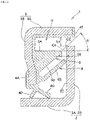
FIG. 1 is an enlarged longitudinal cross-sectional view of a principal portion, showing a state in which a rotary seal according to a first reference that does not form part of the claimed invention is attached to a radially inward member and a radially outward member; -
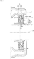
FIG. 2 is an end view of a cut portion taken along a plane including an axial direction of the rotary seal shown inFIG. 1 ; -
FIG. 3 is an enlarged longitudinal cross-sectional view of a principal portion, showing a state in which a rotary seal according to a second reference that does not form part of the claimed invention is attached to a radially inward member and a radially outward member; -
FIG. 4 is an end view of a cut portion taken along a plane including an axial direction of the rotary seal shown inFIG. 3 ; -
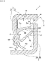
FIG. 5 is an enlarged longitudinal cross-sectional view of a principal portion, showing a state in which a rotary seal according to an embodiment of the present invention is attached to a radially inward member and a radially outward member; -
FIG. 6 is an end view of a cut portion taken along a plane including an axial direction of the rotary seal shown inFIG. 5 ; -
FIG. 7 is an enlarged longitudinal cross-sectional view of a principal portion, showing a state in which a rotary seal according to a third reference that does not form part of the claimed invention is attached to a radially inward member and a radially outward member; -
FIG. 8 is an end view of a cut portion taken along a plane including an axial direction of the rotary seal shown inFIG. 7 ; -
FIG. 9 is an enlarged longitudinal cross-sectional view of a principal portion, showing a state in which a rotary seal according to a fourth reference that does not form part of the claimed invention is attached to a radially inward member and a radially outward member; and -
FIG. 10 is an end view of a cut portion taken along a plane including an axial direction of the rotary seal shown inFIG. 9 . - Next, an explanation will be made in detail with reference to the accompanying drawings.
- Note that, in the present specification, in a state in which a rotary seal is attached to a radially inward member and a radially outward member, a direction of a rotation axis of a radially inner member that is a member on a rotation side will be referred to as an "axial direction", and a direction orthogonal to the axial direction will be referred to as a "radial direction".
- In the following explanation, a description will be given of the case where the axial direction is a horizontal direction; however, the axial direction may be a direction inclined from the horizontal direction. That is, a horizontal rotation axis A in
FIGS. 1 ,3 ,5 ,7 and9 may be an inclined rotation axis. - Moreover, in the radially inward member and the radially outward member, onto which the rotary seal of the present invention is attached, such a case that axial centers of these members are shifted from each other (that is, a case where these members are misaligned with each other) is also included.
- As shown in an enlarged longitudinal cross-sectional view of a principal portion in
FIG. 1 and an end view of a cut portion inFIG. 2 , arotary seal 1 according to a first reference includes aslinger 2, acore metal 3, aseal member 4, and alip wetting inhibitor 5. Therotary seal 1 is used in a state in which theslinger 2 is attached to a radially inner member E and thecore metal 3 is attached to a radially outer member F. - The
slinger 2 is composed of acylindrical portion 2A and anoutward flange portion 2B extending radially outward from an axial end of thecylindrical portion 2A. - The
core metal 3 is composed of acylindrical portion 3A and aninward flange portion 3B extending radially inward from an axial end of thecylindrical portion 3A. - The
slinger 2 and thecore metal 3 are made of, for example, a stainless steel plate by presswork. - The
cylindrical portion 2A of theslinger 2 is attached to the radially inner member E, and thecylindrical portion 3A of thecore metal 3 is attached to the radially outer member F. - To the
core metal 3, abase 4A of theseal member 4 that is an elastic body such as rubber is adhered by vulcanization. - The
seal member 4 has a lip structure including anaxial lip 4B that extends from thebase 4A and is brought into sliding contact with an axiallyinner surface 2C of theoutward flange portion 2B and including aradial lip 4C and agrease lip 4D that are brought into sliding contact with an outer circumferential surface of thecylindrical portion 2A. Moreover, theseal member 4 has an outercircumferential seal portion 4E that covers a tip end of thecylindrical portion 3A, and the outercircumferential seal portion 4E connects to thebase 4A from an inner circumferential surface side of thecylindrical portion 3A. - The
lip wetting inhibitor 5 is integral, for example, with theseal member 4, and is located radially outward of theaxial lip 4B. Moreover, the lip wetting inhibitor5 protrudes axially from thebase 4A toward theoutward flange portion 2B, and inhibits wetting of theaxial lip 4B. - Note that the
lip wetting inhibitor 5 may be a separate body from theseal member 4, and thelip wetting inhibitor 5 being thus separated from theseal member 4 may be joined to thebase 4A or theinward flange portion 3B - The
lip wetting inhibitor 5 being thus separated from theseal member 4 may be made of an elastic body such as rubber, or may be made of a synthetic resin or metal. - A gap D1 shown in
FIG. 2 is defined between a tip end of theoutward flange portion 2B and the outercircumferential seal portion 4E. The gap D1 has a length of 6 to 20% of a radial length of a whole including theslinger 2 and thecore metal 3 in the end view of the cut portion inFIG. 2 . - A lower limit value of the gap D1 is set to a value at which the outer
circumferential seal portion 4E does not contact the tip end of theoutward flange portion 2B of theslinger 2 due to inclined rotation and misalignment depending on mounting and product dimension accuracy. - Note that, in the case where a wraparound portion of a magnetic encoder is provided in a configuration of joining the magnetic encoder to the
outward flange portion 2B of theslinger 2, the lower limit value of the gap D1 is set to a value at which the outercircumferential seal portion 4E does not contact a tip end of the wraparound portion of the magnetic encoder due to the inclined rotation and the misalignment depending on the mounting and product dimension accuracy. - An upper limit value of the gap D1 is set in consideration of drainage and a positional relationship between the
axial lip 4B and thelip wetting inhibitor 5. - As shown by arrow in
FIG. 1 , muddy water or the like that penetrates an atmosphere-side annular cavity portion B from the gap D1 located radially outward of theoutward flange portion 2B is discharged from the gap D1 by gravity. - In the case where the muddy water or the like has penetrated the atmosphere-side annular cavity portion B from the gap D1, direct contact between the muddy water or the like and the
axial lip 4B can be prevented since thelip wetting inhibitor 5 is located radially outward of theaxial lip 4B. Accordingly, wetting possibility of theaxial lip 4B can be reduced. - A gap D2 shown in
FIG. 2 is defined between a tip end of thelip wetting inhibitor 5 and the axiallyinner surface 2C of theoutward flange portion 2B. The gap D2 has a length of 7 to 30% of the axial length of the whole including theslinger 2 and thecore metal 3 in the end view of the cut portion inFIG. 2 . - A lower limit value of the gap D2 is set to a value at which the tip end (for example, a tip end C1 of a radially outer
circumferential surface 5A) of thelip wetting inhibitor 5 does not contact the axiallyinner surface 2C of theslinger 2 or the wraparound portion of the magnetic encoder, depending on the inclined rotation and finished quality of each of theslinger 2, thelip wetting inhibitor 5 and the wraparound portion of the magnetic encoder. - An upper limit value of the gap D2 is set within a range where the
lip wetting inhibitor 5 functions as a receiver for the muddy water or the like which has penetrated the atmosphere-side annular cavity portion B from the gap D1. - Then, even if the
lip wetting inhibitor 5 is applied with a water pressure and is elastically deformed radially, the tip end of thelip wetting inhibitor 5 does not contact the axiallyinner surface 2C of theoutward flange portion 2B. Thus, the tip end of thelip wetting inhibitor 5 is not brought into sliding contact with the axiallyinner surface 2C, and accordingly, torque is not increased by thelip wetting inhibitor 5. - An angle α formed by a straight line that extends along a plane including an axial direction as described below and the axial direction, as shown in
FIG. 2 , is 40° or more to less than 90°. The straight line connects the tip end C1 of the radially outercircumferential surface 5A of thelip wetting inhibitor 5 and an outer circumferential edge C2 of the axiallyinner surface 2C of theoutward flange portion 2B to each other. - That is, if the tip end (for example, the outer circumferential edge C2) of the
outward flange portion 2B of theslinger 2 and the radially outercircumferential surface 5A (the tip end C1) of thelip wetting inhibitor 5 has the same height, then such an effect that thelip wetting inhibitor 5 functions as a receiver for the muddy water or the like which has penetrated the atmosphere-side annular cavity portion B from the gap D1 is reduced. Therefore, the angle α is 40° or more, and the angle α is less than 90° in terms of structure. - By setting the angle α to 40° or more, the muddy water or the like, which has penetrated the atmosphere-side annular cavity portion B from the gap D1, becomes difficult to penetrate the gap D2 between the tip end of the
lip wetting inhibitor 5 and the axiallyinner surface 2C of theoutward flange portion 2B in the case of receiving the muddy water or the like by thelip wetting inhibitor 5. Accordingly, the effect of reducing the wetting possibility of theaxial lip 4B is increased. - In an example, the rotary seal 1 (see
FIGS. 1 and2 ) according to the first reference is used, and in a comparative example, thelip wetting inhibitor 5 is eliminated from therotary seal 1. - The rotary seals of the example and the comparative example are attached to automotive wheel bearings (hub bearings). An outer ring that is the radially outer member F to which the
core metal 3 is fitted is mounted to a position eccentric from an axial center by 0.1 mm by total indicator reading (TIR). - Automotive wheel bearings attached with the rotary seals according to the example and automotive wheel bearings attached with the rotary seals according to the comparative example are fabricated three by three. Axial centers of the respective bearings are set horizontal, and muddy water at a water temperature of 23°C, to which mud (Kanto loam powder) of 10% by weight is mixed, is put to positions of the axial centers of the respective bearings.
- In that state, inner rings which are the radially inner members E are rotated at a rotation speed of 1500 rpm for 70 hours with respect to outer rings. Thereafter, the bearings attached with the rotary seals of the example and the comparative example are observed, and regions which the mud thus penetrated has reached are confirmed.
- The muddy water penetrated each of the automotive wheel bearings attached with the rotary seals of the comparative example.
- In contrast, with regard to each of the automotive wheel bearings attached with the rotary seals 1 of the example, the muddy water penetrated a space between the
radial lip 4C and thegrease lip 4D a little, but never penetrated an inside of each of the bearings. - In the configurations which will be described below, the same reference numerals as those in
FIGS. 1 and2 in the first reference denote the same or equivalent components. - As shown in an enlarged longitudinal cross-sectional view of a principal portion in
FIG. 3 and an end view of a cut portion inFIG. 4 , in arotary seal 1 according to the second reference, the radially outercircumferential surface 5A of thelip wetting inhibitor 5 is a partially conical surface expanding in diameter as approaching theoutward flange portion 2B of theslinger 2. - In this way, the radially outer
circumferential surface 5A of thelip wetting inhibitor 5 is an inclined surface reduced in diameter in a direction of moving away from theoutward flange portion 2B of theslinger 2. - Here, since the radially outer
circumferential surface 5A of thelip wetting inhibitor 5 is the inclined surface, the muddy water or the like, which penetrates the atmosphere-side annular cavity portion B from the gap D1 located radially outward of theoutward flange portion 2B of theslinger 2 and is received by thelip wetting inhibitor 5, is difficult to penetrate the gap D2 between the tip end of thelip wetting inhibitor 5 and the axiallyinner surface 2C of theoutward flange portion 2B. Accordingly, the effect of reducing the wetting possibility of theaxial lip 4B is further increased. - As shown in an enlarged longitudinal cross-sectional view of a principal portion in
FIG. 5 and an end view of a cut portion inFIG. 6 , in arotary seal 1 according to a preferred embodiment of the present invention, abrim portion 5C that protrudes radially outward is provided on a tip end portion of the radially outercircumferential surface 5A of thelip wetting inhibitor 5. - Here, the muddy water or the like, which penetrates the atmosphere-side annular cavity portion B from the gap D1 located radially outward of the
outward flange portion 2B of theslinger 2 and is received by thelip wetting inhibitor 5, is difficult to penetrate the gap D2 between the tip end of thelip wetting inhibitor 5 and the axiallyinner surface 2C of theoutward flange portion 2B beyond thebrim portion 5C that is provided on the tip end portion of the radially outercircumferential surface 5A of thelip wetting inhibitor 5 and protrudes radially outward. Accordingly, the effect of reducing the wetting possibility of theaxial lip 4B is further increased. - Note that, in the configuration as in the second reference in which the radially outer
circumferential surface 5A of thelip wetting inhibitor 5 is the inclined surface reduced in diameter in the direction of moving away from theoutward flange portion 2B of theslinger 2, thebrim portion 5C that protrudes radially outward may be provided. - As shown in an enlarged longitudinal cross-sectional view of a principal portion in
FIG. 7 and an end view of a cut portion inFIG. 8 , in arotary seal 1 according to the third reference, the radially outercircumferential surface 5A of thelip wetting inhibitor 5 is a cylindrical surface similar to that in the first reference (FIG. 2 ). Moreover, the radially innercircumferential surface 5B of thelip wetting inhibitor 5 has a shape extending from a position apart from a base end portion of theaxial lip 4B toward theoutward flange portion 2B of theslinger 2. That is, thelip wetting inhibitor 5 has a substantially cylindrical shape. - In this way, a space G between the
axial lip 4B and thelip wetting inhibitor 5 located radially outward of theaxial lip 4B is increased. Therefore, in the case where the muddy water or the like has penetrated the space G from the gap D2 between the tip end of thelip wetting inhibitor 5 and the axiallyinner surface 2C of theoutward flange portion 2B, the muddy water or the like resides in a space on a root side of theaxial lip 4B. Accordingly, the muddy water or the like is difficult to reach the tip end of theaxial lip 4B. - Hence, even if the muddy water or the like in the space G is dried and is turned to mud that is a solid, such a possibility that the mud may penetrate the sliding contact portion between the axially
inner surface 2C of theoutward flange portion 2B and theaxial lip 4B to result in the deterioration of the followability of the lip is reduced. Accordingly, such an apprehension that the sealing performance may decrease is reduced. - In addition, since the
lip wetting inhibitor 5 has a substantially cylindrical shape, the volume of thelip wetting inhibitor 5 is reduced. Accordingly, the manufacturing cost of therotary seal 1 can be reduced, and the weight of therotary seal 1 can be reduced. - As shown in an enlarged longitudinal cross-sectional view of a principal portion in
FIG. 9 and an end view of a cut portion inFIG. 10 , in arotary seal 1 according to the fourth reference, the radially outercircumferential surface 5A of thelip wetting inhibitor 5 is an inclined surface similar to that in the second reference (FIG. 4 ). Moreover, the radially innercircumferential surface 5B of thelip wetting inhibitor 5 has a shape extending from the position apart from the base end portion of theaxial lip 4B toward theoutward flange portion 2B of theslinger 2. That is, thelip wetting inhibitor 5 has a substantially truncated conical cylindrical shape. - In this way, the fourth reference produces the same functions and effects as those in the second reference (
FIG. 4 ) and the third reference (FIG. 8 ). - The
rotary seal 1 of the present invention includes thelip wetting inhibitor 5 radially outward of theaxial lip 4B. Accordingly, the direct contact between theaxial lip 4B and the muddy water or the like which has penetrated the atmosphere-side annular cavity portion B from the gap D1 located radially outward of theoutward flange portion 2B of theslinger 2 can be prevented. - Hence, the gap D1 may be extended to a size at which the gap D1 does not function as the labyrinth seal. In this way, the muddy water or the like, which has penetrated the atmosphere-side annular cavity portion B, is easily discharged from the gap D1 by gravity.
Claims (3)
- A rotary seal (1) that includes:a slinger (2) including a cylindrical portion (2A) and an outward flange portion (2B) extending radially outward from an axial end of the cylindrical portion (2A);a core metal (3) including a cylindrical portion (3A) and an inward flange portion (3B) extending radially inward from an axial end of the cylindrical portion (3A); anda seal member (4) including a base (4A) joined to the core metal (3) and a seal lip including an axial lip (4B) that extends from the base (4A) and is brought into sliding contact with an axially inner surface (2C) of the outward flange portion (2B),the rotary seal (1) for being used in a state where the cylindrical portion (2A) of the slinger (2) is attached to an inner ring of an automobile wheel bearing, the inner ring being a radially inner member (E), and the cylindrical portion (3A) of the core metal (3) is attached to an outer ring of the automobile wheel bearing, the outer ring being a radially outer member (F), the rotary seal (1) comprisinga lip wetting inhibitor (5) that is located radially outward of the axial lip (4B) and protrudes axially from the base (4A) or the inward flange portion (3B) toward the outward flange portion (2B),wherein a first gap (D1) is provided between a tip end of the outward flange portion (2B) of the slinger (2) and an outer circumferential seal portion (4E) that covers a tip end of the cylindrical portion (3A) of the core metal (3), or between an outer circumferential seal portion (4E) that covers a tip end of the cylindrical portion (3A) of the core metal (3) and a wraparound portion of a magnetic encoder joined to the outward flange portion (2B) of the slinger (2),a second gap (D2) is provided between a tip end of the lip wetting inhibitor (5) and the axially inner surface (2C) of the outward flange portion (2B) or between the tip end of the lip wetting inhibitor (5) and the wraparound portion of the magnetic encoder joined to the outward flange portion (2B),an angle (α) formed by an axial direction and a straight line in the end view of the cut portion is 40° or more and less than 90°, the straight line connecting a tip end (C1) of a radially outer circumferential surface (5A) of the lip wetting inhibitor (5) and an outer circumferential edge (C2) of the axially inner surface (2C) of the outward flange portion (2B) to each other,the tip end of the lip wetting inhibitor (5) does not contact the axially inner surface (2C) even when the lip wetting inhibitor (5) is applied with a water pressure and elastically deformed, anda brim portion (5C) that protrudes radially outward is provided on a tip end portion of the radially outer circumferential surface (5A) of the lip wetting inhibitor (5).
- The rotary seal (1) according to claim 1, wherein the radially outer circumferential surface (5A) of the lip wetting inhibitor (5) is a partially conical surface expanding in diameter as approaching the outward flange portion (2B).
- The rotary seal (1) according to claim 1 or 2, whereina radially inner circumferential surface (5B) of the lip wetting inhibitor (5) has a shape extending from a position apart from a base end portion of the axial lip (4B) toward the outward flange portion (2B), andthe lip wetting inhibitor (5) has a substantially cylindrical shape or a substantially truncated conical cylindrical shape.
Applications Claiming Priority (1)
| Application Number | Priority Date | Filing Date | Title |
|---|---|---|---|
| JP2017138743A JP7052237B2 (en) | 2017-07-18 | 2017-07-18 | Rotating sticker |
Publications (2)
| Publication Number | Publication Date |
|---|---|
| EP3431834A1 EP3431834A1 (en) | 2019-01-23 |
| EP3431834B1 true EP3431834B1 (en) | 2022-11-02 |
Family
ID=62909409
Family Applications (1)
| Application Number | Title | Priority Date | Filing Date |
|---|---|---|---|
| EP18182589.4A Active EP3431834B1 (en) | 2017-07-18 | 2018-07-10 | Rotary seal |
Country Status (4)
| Country | Link |
|---|---|
| US (1) | US10634193B2 (en) |
| EP (1) | EP3431834B1 (en) |
| JP (1) | JP7052237B2 (en) |
| CN (1) | CN109268506B (en) |
Families Citing this family (5)
| Publication number | Priority date | Publication date | Assignee | Title |
|---|---|---|---|---|
| JP6857479B2 (en) * | 2016-10-07 | 2021-04-14 | Nok株式会社 | Sealing device |
| JP7449136B2 (en) * | 2020-03-24 | 2024-03-13 | Ntn株式会社 | Sealed rolling bearing |
| JPWO2021220576A1 (en) * | 2020-04-28 | 2021-11-04 | ||
| JP7505368B2 (en) * | 2020-10-28 | 2024-06-25 | 住友電装株式会社 | Grommet |
| JP7649667B2 (en) | 2021-03-23 | 2025-03-21 | Ntn株式会社 | Sealing device for wheel bearing device and wheel bearing device equipped with same |
Citations (2)
| Publication number | Priority date | Publication date | Assignee | Title |
|---|---|---|---|---|
| EP2693068A1 (en) * | 2011-03-30 | 2014-02-05 | NTN Corporation | Bearing device for wheel |
| JP2015152030A (en) * | 2014-02-10 | 2015-08-24 | Ntn株式会社 | SEALING DEVICE AND WHEEL BEARING DEVICE HAVING THE SAME |
Family Cites Families (21)
| Publication number | Priority date | Publication date | Assignee | Title |
|---|---|---|---|---|
| JPS62283261A (en) | 1986-05-29 | 1987-12-09 | Uchiyama Mfg Corp | Combined seal |
| JP2001065704A (en) | 1999-08-31 | 2001-03-16 | Ntn Corp | Sealing device |
| JP4200705B2 (en) * | 2002-08-02 | 2008-12-24 | 日本精工株式会社 | Rolling bearing unit with seal ring |
| CN2752528Y (en) * | 2004-06-15 | 2006-01-18 | 万向钱潮股份有限公司 | Wheel hub bearing unit sealing structure |
| US20090127796A1 (en) * | 2005-06-07 | 2009-05-21 | Nok Corporation | Sealing device |
| JP2007285374A (en) * | 2006-04-14 | 2007-11-01 | Ntn Corp | Bearing device for wheel |
| JP2008128396A (en) * | 2006-11-22 | 2008-06-05 | Jtekt Corp | Sealing device |
| JP5170366B2 (en) | 2007-02-22 | 2013-03-27 | Nok株式会社 | Sealing device |
| WO2009144785A1 (en) * | 2008-05-27 | 2009-12-03 | 日本精工株式会社 | Rolling bearing |
| JP5327603B2 (en) * | 2008-08-05 | 2013-10-30 | 株式会社ジェイテクト | Rolling bearing device |
| DE102009050215A1 (en) * | 2009-10-22 | 2011-05-12 | Schaeffler Technologies Gmbh & Co. Kg | Non-abrasive sealing ring and seal assembly |
| JP2014224546A (en) * | 2013-05-15 | 2014-12-04 | 日本精工株式会社 | Roller bearing unit with combination seal ring |
| JP6275465B2 (en) * | 2013-12-06 | 2018-02-07 | Ntn株式会社 | SEALING DEVICE AND WHEEL BEARING DEVICE HAVING THE SAME |
| JP2016080141A (en) * | 2014-10-22 | 2016-05-16 | 光洋シーリングテクノ株式会社 | Sealing device |
| KR101681270B1 (en) * | 2015-01-30 | 2016-12-12 | 주식회사 일진글로벌 | Sealing structure of wheel bearing for vehicle |
| JP2016186319A (en) * | 2015-03-27 | 2016-10-27 | Ntn株式会社 | Sealing device and wheel bearing device having the same |
| JP6603078B2 (en) * | 2015-08-31 | 2019-11-06 | Ntn株式会社 | Wheel bearing device |
| KR20180033279A (en) * | 2015-09-01 | 2018-04-02 | 엔오케이 가부시키가이샤 | Sealing device |
| JP6717524B2 (en) * | 2015-09-16 | 2020-07-01 | Ntn株式会社 | Wheel bearing device |
| EP3339693B1 (en) * | 2015-10-09 | 2020-06-10 | Nok Corporation | Sealing apparatus |
| JP6857479B2 (en) * | 2016-10-07 | 2021-04-14 | Nok株式会社 | Sealing device |
-
2017
- 2017-07-18 JP JP2017138743A patent/JP7052237B2/en active Active
-
2018
- 2018-07-02 CN CN201810704579.8A patent/CN109268506B/en active Active
- 2018-07-10 EP EP18182589.4A patent/EP3431834B1/en active Active
- 2018-07-12 US US16/033,696 patent/US10634193B2/en active Active
Patent Citations (2)
| Publication number | Priority date | Publication date | Assignee | Title |
|---|---|---|---|---|
| EP2693068A1 (en) * | 2011-03-30 | 2014-02-05 | NTN Corporation | Bearing device for wheel |
| JP2015152030A (en) * | 2014-02-10 | 2015-08-24 | Ntn株式会社 | SEALING DEVICE AND WHEEL BEARING DEVICE HAVING THE SAME |
Also Published As
| Publication number | Publication date |
|---|---|
| CN109268506A (en) | 2019-01-25 |
| CN109268506B (en) | 2020-08-11 |
| EP3431834A1 (en) | 2019-01-23 |
| JP7052237B2 (en) | 2022-04-12 |
| US10634193B2 (en) | 2020-04-28 |
| US20190024717A1 (en) | 2019-01-24 |
| JP2019019894A (en) | 2019-02-07 |
Similar Documents
| Publication | Publication Date | Title |
|---|---|---|
| US10634193B2 (en) | Rotary seal | |
| EP2685118B1 (en) | Wheel hub rolling bearing assembly for a motor vehicle with a sealing device | |
| CN107269711B (en) | Low friction sealing device and rolling bearing equipped therewith | |
| US10746229B2 (en) | Wheel bearing sealing device and manufacturing method therefor | |
| US20110006485A1 (en) | Sealing device | |
| EP2639468B1 (en) | Rolling bearing unit | |
| US9494196B2 (en) | Bearing device, a sensor-bearing unit and an apparatus comprising at least one such bearing device | |
| EP3184864B1 (en) | Sealing structure | |
| EP2721327B1 (en) | Radial shaft seal, radial shaft seal assembly and method of installation | |
| EP3222891B1 (en) | Sealing structure | |
| EP3012475A1 (en) | Hub-bearing unit with a sealing device | |
| US20110193294A1 (en) | Sealing device | |
| WO2013184611A1 (en) | Radial shaft seal and assembly therewith | |
| WO2018110626A1 (en) | Sealing device | |
| EP2748494B1 (en) | Radial shaft seal with dust exclusion and hydrodynamic sealing feature | |
| JP2017190804A (en) | Seal | |
| US9458937B2 (en) | Shaft seal assembly with exclusion pump dust lip | |
| US20190390714A1 (en) | Bearing assembly with an improved sealing ring | |
| US11009076B2 (en) | Rotary seal | |
| JP6625340B2 (en) | Sealing device | |
| EP2551542B1 (en) | Wheel-hub bearing/constant-velocity joint unit provided with a protective screen | |
| US20230029313A1 (en) | Sealing assembly for insertion between a stationary annular element and a rotating annular element, in particular between the outer and inner rings of a rolling bearing and associated wheel hub unit | |
| EP3273118B1 (en) | Sealing device | |
| JP2020090970A (en) | Seal device | |
| JP5223440B2 (en) | Wheel bearing |
Legal Events
| Date | Code | Title | Description |
|---|---|---|---|
| PUAI | Public reference made under article 153(3) epc to a published international application that has entered the european phase |
Free format text: ORIGINAL CODE: 0009012 |
|
| STAA | Information on the status of an ep patent application or granted ep patent |
Free format text: STATUS: THE APPLICATION HAS BEEN PUBLISHED |
|
| AK | Designated contracting states |
Kind code of ref document: A1 Designated state(s): AL AT BE BG CH CY CZ DE DK EE ES FI FR GB GR HR HU IE IS IT LI LT LU LV MC MK MT NL NO PL PT RO RS SE SI SK SM TR |
|
| AX | Request for extension of the european patent |
Extension state: BA ME |
|
| STAA | Information on the status of an ep patent application or granted ep patent |
Free format text: STATUS: REQUEST FOR EXAMINATION WAS MADE |
|
| 17P | Request for examination filed |
Effective date: 20190723 |
|
| RBV | Designated contracting states (corrected) |
Designated state(s): AL AT BE BG CH CY CZ DE DK EE ES FI FR GB GR HR HU IE IS IT LI LT LU LV MC MK MT NL NO PL PT RO RS SE SI SK SM TR |
|
| STAA | Information on the status of an ep patent application or granted ep patent |
Free format text: STATUS: EXAMINATION IS IN PROGRESS |
|
| RIC1 | Information provided on ipc code assigned before grant |
Ipc: F16J 15/3264 20160101AFI20200213BHEP |
|
| 17Q | First examination report despatched |
Effective date: 20200316 |
|
| GRAP | Despatch of communication of intention to grant a patent |
Free format text: ORIGINAL CODE: EPIDOSNIGR1 |
|
| STAA | Information on the status of an ep patent application or granted ep patent |
Free format text: STATUS: GRANT OF PATENT IS INTENDED |
|
| INTG | Intention to grant announced |
Effective date: 20220627 |
|
| GRAS | Grant fee paid |
Free format text: ORIGINAL CODE: EPIDOSNIGR3 |
|
| GRAA | (expected) grant |
Free format text: ORIGINAL CODE: 0009210 |
|
| STAA | Information on the status of an ep patent application or granted ep patent |
Free format text: STATUS: THE PATENT HAS BEEN GRANTED |
|
| AK | Designated contracting states |
Kind code of ref document: B1 Designated state(s): AL AT BE BG CH CY CZ DE DK EE ES FI FR GB GR HR HU IE IS IT LI LT LU LV MC MK MT NL NO PL PT RO RS SE SI SK SM TR |
|
| REG | Reference to a national code |
Ref country code: GB Ref legal event code: FG4D |
|
| RIN1 | Information on inventor provided before grant (corrected) |
Inventor name: IIZAWA, YUSUKE Inventor name: AKASHI, SHINICHI Inventor name: SATO, TAKAHIKO |
|
| REG | Reference to a national code |
Ref country code: CH Ref legal event code: EP Ref country code: AT Ref legal event code: REF Ref document number: 1528962 Country of ref document: AT Kind code of ref document: T Effective date: 20221115 |
|
| REG | Reference to a national code |
Ref country code: DE Ref legal event code: R096 Ref document number: 602018042476 Country of ref document: DE |
|
| REG | Reference to a national code |
Ref country code: IE Ref legal event code: FG4D |
|
| REG | Reference to a national code |
Ref country code: LT Ref legal event code: MG9D |
|
| REG | Reference to a national code |
Ref country code: NL Ref legal event code: MP Effective date: 20221102 |
|
| REG | Reference to a national code |
Ref country code: AT Ref legal event code: MK05 Ref document number: 1528962 Country of ref document: AT Kind code of ref document: T Effective date: 20221102 |
|
| PG25 | Lapsed in a contracting state [announced via postgrant information from national office to epo] |
Ref country code: SE Free format text: LAPSE BECAUSE OF FAILURE TO SUBMIT A TRANSLATION OF THE DESCRIPTION OR TO PAY THE FEE WITHIN THE PRESCRIBED TIME-LIMIT Effective date: 20221102 Ref country code: PT Free format text: LAPSE BECAUSE OF FAILURE TO SUBMIT A TRANSLATION OF THE DESCRIPTION OR TO PAY THE FEE WITHIN THE PRESCRIBED TIME-LIMIT Effective date: 20230302 Ref country code: NO Free format text: LAPSE BECAUSE OF FAILURE TO SUBMIT A TRANSLATION OF THE DESCRIPTION OR TO PAY THE FEE WITHIN THE PRESCRIBED TIME-LIMIT Effective date: 20230202 Ref country code: LT Free format text: LAPSE BECAUSE OF FAILURE TO SUBMIT A TRANSLATION OF THE DESCRIPTION OR TO PAY THE FEE WITHIN THE PRESCRIBED TIME-LIMIT Effective date: 20221102 Ref country code: FI Free format text: LAPSE BECAUSE OF FAILURE TO SUBMIT A TRANSLATION OF THE DESCRIPTION OR TO PAY THE FEE WITHIN THE PRESCRIBED TIME-LIMIT Effective date: 20221102 Ref country code: ES Free format text: LAPSE BECAUSE OF FAILURE TO SUBMIT A TRANSLATION OF THE DESCRIPTION OR TO PAY THE FEE WITHIN THE PRESCRIBED TIME-LIMIT Effective date: 20221102 Ref country code: AT Free format text: LAPSE BECAUSE OF FAILURE TO SUBMIT A TRANSLATION OF THE DESCRIPTION OR TO PAY THE FEE WITHIN THE PRESCRIBED TIME-LIMIT Effective date: 20221102 |
|
| PG25 | Lapsed in a contracting state [announced via postgrant information from national office to epo] |
Ref country code: RS Free format text: LAPSE BECAUSE OF FAILURE TO SUBMIT A TRANSLATION OF THE DESCRIPTION OR TO PAY THE FEE WITHIN THE PRESCRIBED TIME-LIMIT Effective date: 20221102 Ref country code: PL Free format text: LAPSE BECAUSE OF FAILURE TO SUBMIT A TRANSLATION OF THE DESCRIPTION OR TO PAY THE FEE WITHIN THE PRESCRIBED TIME-LIMIT Effective date: 20221102 Ref country code: LV Free format text: LAPSE BECAUSE OF FAILURE TO SUBMIT A TRANSLATION OF THE DESCRIPTION OR TO PAY THE FEE WITHIN THE PRESCRIBED TIME-LIMIT Effective date: 20221102 Ref country code: IS Free format text: LAPSE BECAUSE OF FAILURE TO SUBMIT A TRANSLATION OF THE DESCRIPTION OR TO PAY THE FEE WITHIN THE PRESCRIBED TIME-LIMIT Effective date: 20230302 Ref country code: HR Free format text: LAPSE BECAUSE OF FAILURE TO SUBMIT A TRANSLATION OF THE DESCRIPTION OR TO PAY THE FEE WITHIN THE PRESCRIBED TIME-LIMIT Effective date: 20221102 Ref country code: GR Free format text: LAPSE BECAUSE OF FAILURE TO SUBMIT A TRANSLATION OF THE DESCRIPTION OR TO PAY THE FEE WITHIN THE PRESCRIBED TIME-LIMIT Effective date: 20230203 |
|
| PG25 | Lapsed in a contracting state [announced via postgrant information from national office to epo] |
Ref country code: NL Free format text: LAPSE BECAUSE OF FAILURE TO SUBMIT A TRANSLATION OF THE DESCRIPTION OR TO PAY THE FEE WITHIN THE PRESCRIBED TIME-LIMIT Effective date: 20221102 |
|
| PG25 | Lapsed in a contracting state [announced via postgrant information from national office to epo] |
Ref country code: SM Free format text: LAPSE BECAUSE OF FAILURE TO SUBMIT A TRANSLATION OF THE DESCRIPTION OR TO PAY THE FEE WITHIN THE PRESCRIBED TIME-LIMIT Effective date: 20221102 Ref country code: RO Free format text: LAPSE BECAUSE OF FAILURE TO SUBMIT A TRANSLATION OF THE DESCRIPTION OR TO PAY THE FEE WITHIN THE PRESCRIBED TIME-LIMIT Effective date: 20221102 Ref country code: EE Free format text: LAPSE BECAUSE OF FAILURE TO SUBMIT A TRANSLATION OF THE DESCRIPTION OR TO PAY THE FEE WITHIN THE PRESCRIBED TIME-LIMIT Effective date: 20221102 Ref country code: DK Free format text: LAPSE BECAUSE OF FAILURE TO SUBMIT A TRANSLATION OF THE DESCRIPTION OR TO PAY THE FEE WITHIN THE PRESCRIBED TIME-LIMIT Effective date: 20221102 Ref country code: CZ Free format text: LAPSE BECAUSE OF FAILURE TO SUBMIT A TRANSLATION OF THE DESCRIPTION OR TO PAY THE FEE WITHIN THE PRESCRIBED TIME-LIMIT Effective date: 20221102 |
|
| REG | Reference to a national code |
Ref country code: DE Ref legal event code: R097 Ref document number: 602018042476 Country of ref document: DE |
|
| PG25 | Lapsed in a contracting state [announced via postgrant information from national office to epo] |
Ref country code: SK Free format text: LAPSE BECAUSE OF FAILURE TO SUBMIT A TRANSLATION OF THE DESCRIPTION OR TO PAY THE FEE WITHIN THE PRESCRIBED TIME-LIMIT Effective date: 20221102 Ref country code: AL Free format text: LAPSE BECAUSE OF FAILURE TO SUBMIT A TRANSLATION OF THE DESCRIPTION OR TO PAY THE FEE WITHIN THE PRESCRIBED TIME-LIMIT Effective date: 20221102 |
|
| PLBE | No opposition filed within time limit |
Free format text: ORIGINAL CODE: 0009261 |
|
| STAA | Information on the status of an ep patent application or granted ep patent |
Free format text: STATUS: NO OPPOSITION FILED WITHIN TIME LIMIT |
|
| 26N | No opposition filed |
Effective date: 20230803 |
|
| PG25 | Lapsed in a contracting state [announced via postgrant information from national office to epo] |
Ref country code: SI Free format text: LAPSE BECAUSE OF FAILURE TO SUBMIT A TRANSLATION OF THE DESCRIPTION OR TO PAY THE FEE WITHIN THE PRESCRIBED TIME-LIMIT Effective date: 20221102 |
|
| PG25 | Lapsed in a contracting state [announced via postgrant information from national office to epo] |
Ref country code: MC Free format text: LAPSE BECAUSE OF FAILURE TO SUBMIT A TRANSLATION OF THE DESCRIPTION OR TO PAY THE FEE WITHIN THE PRESCRIBED TIME-LIMIT Effective date: 20221102 |
|
| PG25 | Lapsed in a contracting state [announced via postgrant information from national office to epo] |
Ref country code: MC Free format text: LAPSE BECAUSE OF FAILURE TO SUBMIT A TRANSLATION OF THE DESCRIPTION OR TO PAY THE FEE WITHIN THE PRESCRIBED TIME-LIMIT Effective date: 20221102 |
|
| REG | Reference to a national code |
Ref country code: CH Ref legal event code: PL |
|
| REG | Reference to a national code |
Ref country code: BE Ref legal event code: MM Effective date: 20230731 |
|
| PG25 | Lapsed in a contracting state [announced via postgrant information from national office to epo] |
Ref country code: LU Free format text: LAPSE BECAUSE OF NON-PAYMENT OF DUE FEES Effective date: 20230710 |
|
| GBPC | Gb: european patent ceased through non-payment of renewal fee |
Effective date: 20230710 |
|
| PG25 | Lapsed in a contracting state [announced via postgrant information from national office to epo] |
Ref country code: LU Free format text: LAPSE BECAUSE OF NON-PAYMENT OF DUE FEES Effective date: 20230710 |
|
| REG | Reference to a national code |
Ref country code: IE Ref legal event code: MM4A |
|
| PG25 | Lapsed in a contracting state [announced via postgrant information from national office to epo] |
Ref country code: CH Free format text: LAPSE BECAUSE OF NON-PAYMENT OF DUE FEES Effective date: 20230731 Ref country code: GB Free format text: LAPSE BECAUSE OF NON-PAYMENT OF DUE FEES Effective date: 20230710 |
|
| PG25 | Lapsed in a contracting state [announced via postgrant information from national office to epo] |
Ref country code: IT Free format text: LAPSE BECAUSE OF FAILURE TO SUBMIT A TRANSLATION OF THE DESCRIPTION OR TO PAY THE FEE WITHIN THE PRESCRIBED TIME-LIMIT Effective date: 20221102 Ref country code: FR Free format text: LAPSE BECAUSE OF NON-PAYMENT OF DUE FEES Effective date: 20230731 Ref country code: BE Free format text: LAPSE BECAUSE OF NON-PAYMENT OF DUE FEES Effective date: 20230731 |
|
| PG25 | Lapsed in a contracting state [announced via postgrant information from national office to epo] |
Ref country code: IE Free format text: LAPSE BECAUSE OF NON-PAYMENT OF DUE FEES Effective date: 20230710 |
|
| PG25 | Lapsed in a contracting state [announced via postgrant information from national office to epo] |
Ref country code: IE Free format text: LAPSE BECAUSE OF NON-PAYMENT OF DUE FEES Effective date: 20230710 |
|
| PG25 | Lapsed in a contracting state [announced via postgrant information from national office to epo] |
Ref country code: BG Free format text: LAPSE BECAUSE OF FAILURE TO SUBMIT A TRANSLATION OF THE DESCRIPTION OR TO PAY THE FEE WITHIN THE PRESCRIBED TIME-LIMIT Effective date: 20221102 |
|
| PG25 | Lapsed in a contracting state [announced via postgrant information from national office to epo] |
Ref country code: BG Free format text: LAPSE BECAUSE OF FAILURE TO SUBMIT A TRANSLATION OF THE DESCRIPTION OR TO PAY THE FEE WITHIN THE PRESCRIBED TIME-LIMIT Effective date: 20221102 |
|
| PG25 | Lapsed in a contracting state [announced via postgrant information from national office to epo] |
Ref country code: CY Free format text: LAPSE BECAUSE OF FAILURE TO SUBMIT A TRANSLATION OF THE DESCRIPTION OR TO PAY THE FEE WITHIN THE PRESCRIBED TIME-LIMIT; INVALID AB INITIO Effective date: 20180710 |
|
| PG25 | Lapsed in a contracting state [announced via postgrant information from national office to epo] |
Ref country code: HU Free format text: LAPSE BECAUSE OF FAILURE TO SUBMIT A TRANSLATION OF THE DESCRIPTION OR TO PAY THE FEE WITHIN THE PRESCRIBED TIME-LIMIT; INVALID AB INITIO Effective date: 20180710 |
|
| PGFP | Annual fee paid to national office [announced via postgrant information from national office to epo] |
Ref country code: DE Payment date: 20250731 Year of fee payment: 8 |
|
| PG25 | Lapsed in a contracting state [announced via postgrant information from national office to epo] |
Ref country code: TR Free format text: LAPSE BECAUSE OF FAILURE TO SUBMIT A TRANSLATION OF THE DESCRIPTION OR TO PAY THE FEE WITHIN THE PRESCRIBED TIME-LIMIT Effective date: 20221102 |