EP3431833B1 - Metal to metal wedge ring seal - Google Patents
Metal to metal wedge ring seal Download PDFInfo
- Publication number
- EP3431833B1 EP3431833B1 EP18174328.7A EP18174328A EP3431833B1 EP 3431833 B1 EP3431833 B1 EP 3431833B1 EP 18174328 A EP18174328 A EP 18174328A EP 3431833 B1 EP3431833 B1 EP 3431833B1
- Authority
- EP
- European Patent Office
- Prior art keywords
- circular cross
- metallic ring
- seal assembly
- section metallic
- wedge
- Prior art date
- Legal status (The legal status is an assumption and is not a legal conclusion. Google has not performed a legal analysis and makes no representation as to the accuracy of the status listed.)
- Active
Links
Images

Classifications
-
- F—MECHANICAL ENGINEERING; LIGHTING; HEATING; WEAPONS; BLASTING
- F16—ENGINEERING ELEMENTS AND UNITS; GENERAL MEASURES FOR PRODUCING AND MAINTAINING EFFECTIVE FUNCTIONING OF MACHINES OR INSTALLATIONS; THERMAL INSULATION IN GENERAL
- F16L—PIPES; JOINTS OR FITTINGS FOR PIPES; SUPPORTS FOR PIPES, CABLES OR PROTECTIVE TUBING; MEANS FOR THERMAL INSULATION IN GENERAL
- F16L17/00—Joints with packing adapted to sealing by fluid pressure
- F16L17/02—Joints with packing adapted to sealing by fluid pressure with sealing rings arranged between outer surface of pipe and inner surface of sleeve or socket
-
- E—FIXED CONSTRUCTIONS
- E21—EARTH OR ROCK DRILLING; MINING
- E21B—EARTH OR ROCK DRILLING; OBTAINING OIL, GAS, WATER, SOLUBLE OR MELTABLE MATERIALS OR A SLURRY OF MINERALS FROM WELLS
- E21B33/00—Sealing or packing boreholes or wells
- E21B33/10—Sealing or packing boreholes or wells in the borehole
- E21B33/12—Packers; Plugs
- E21B33/1208—Packers; Plugs characterised by the construction of the sealing or packing means
- E21B33/1212—Packers; Plugs characterised by the construction of the sealing or packing means including a metal-to-metal seal element
-
- F—MECHANICAL ENGINEERING; LIGHTING; HEATING; WEAPONS; BLASTING
- F16—ENGINEERING ELEMENTS AND UNITS; GENERAL MEASURES FOR PRODUCING AND MAINTAINING EFFECTIVE FUNCTIONING OF MACHINES OR INSTALLATIONS; THERMAL INSULATION IN GENERAL
- F16J—PISTONS; CYLINDERS; SEALINGS
- F16J15/00—Sealings
- F16J15/02—Sealings between relatively-stationary surfaces
- F16J15/06—Sealings between relatively-stationary surfaces with solid packing compressed between sealing surfaces
- F16J15/08—Sealings between relatively-stationary surfaces with solid packing compressed between sealing surfaces with exclusively metal packing
- F16J15/0887—Sealings between relatively-stationary surfaces with solid packing compressed between sealing surfaces with exclusively metal packing the sealing effect being obtained by elastic deformation of the packing
-
- F—MECHANICAL ENGINEERING; LIGHTING; HEATING; WEAPONS; BLASTING
- F16—ENGINEERING ELEMENTS AND UNITS; GENERAL MEASURES FOR PRODUCING AND MAINTAINING EFFECTIVE FUNCTIONING OF MACHINES OR INSTALLATIONS; THERMAL INSULATION IN GENERAL
- F16J—PISTONS; CYLINDERS; SEALINGS
- F16J15/00—Sealings
- F16J15/02—Sealings between relatively-stationary surfaces
- F16J15/06—Sealings between relatively-stationary surfaces with solid packing compressed between sealing surfaces
- F16J15/10—Sealings between relatively-stationary surfaces with solid packing compressed between sealing surfaces with non-metallic packing
-
- F—MECHANICAL ENGINEERING; LIGHTING; HEATING; WEAPONS; BLASTING
- F16—ENGINEERING ELEMENTS AND UNITS; GENERAL MEASURES FOR PRODUCING AND MAINTAINING EFFECTIVE FUNCTIONING OF MACHINES OR INSTALLATIONS; THERMAL INSULATION IN GENERAL
- F16J—PISTONS; CYLINDERS; SEALINGS
- F16J15/00—Sealings
- F16J15/16—Sealings between relatively-moving surfaces
- F16J15/164—Sealings between relatively-moving surfaces the sealing action depending on movements; pressure difference, temperature or presence of leaking fluid
-
- F—MECHANICAL ENGINEERING; LIGHTING; HEATING; WEAPONS; BLASTING
- F16—ENGINEERING ELEMENTS AND UNITS; GENERAL MEASURES FOR PRODUCING AND MAINTAINING EFFECTIVE FUNCTIONING OF MACHINES OR INSTALLATIONS; THERMAL INSULATION IN GENERAL
- F16J—PISTONS; CYLINDERS; SEALINGS
- F16J15/00—Sealings
- F16J15/16—Sealings between relatively-moving surfaces
- F16J15/26—Sealings between relatively-moving surfaces with stuffing-boxes for rigid sealing rings
- F16J15/28—Sealings between relatively-moving surfaces with stuffing-boxes for rigid sealing rings with sealing rings made of metal
Definitions
- the present disclosure relates to a metal to metal wedge ring seal.
- seal rings When connecting adjacent sections of fluid flow conduits or vessels, seal rings are typically interposed at the interface of adjacent connecting conduits or vessel portions which are then bolted or clamped together.
- Most known seal rings and joints work, to a greater or lesser extent, when the pressure within the conduit, pressure vessel or the like is considerably greater than the ambient pressure outside of the conduit, pressure vessel or the like so that the seal or joint is pressure energized.
- a locking connector is known from document US 2014/0130329 A1 , wherein coil springs are used to engage an inner member within the bore of an outer member.
- a sealing device for valves is known from United States Patent US 4 477 057 A .
- Shaft seals and particularly a pressure actuated packing system for submarine periscopes are known from document US 2 791 194 A .
- document GB 830 062 A discloses sealing arrangements for use between two relatively rotatable members. From document US 727 839 A a packing for the stuffing-boxes of piston-rods and the like for use with steam or water or any high pressure is known. Further, document US 4 462 568 A discloses a valve construction having improved seal means.
- a seal assembly includes an outer member defining a bore and an inner member received in the bore of the outer member and one of the outer member and the inner member defining a shoulder portion.
- An inner circular cross-section metallic ring member and an outer circular cross-section metallic ring member are disposed between the outer member and inner member and against the shoulder portion.
- a wedge member engages the inner circular cross-section metallic ring member and the outer circular cross-section metallic ring member for applying an axial force against each of the inner and outer circular cross-section metallic ring members in a direction toward the shoulder portion and for applying a radially outer force against the outer circular cross-section metallic ring member and for applying a radially inner force against the inner circular cross-section metallic ring member.
- Example embodiments are provided so that this disclosure will be thorough, and will fully convey the scope to those who are skilled in the art. Numerous specific details are set forth such as examples of specific components, devices, and methods, to provide a thorough understanding of embodiments of the present disclosure. It will be apparent to those skilled in the art that specific details need not be employed, that example embodiments may be embodied in many different forms and that neither should be construed to limit the scope of the disclosure. In some example embodiments, well-known processes, well-known device structures, and well-known technologies are not described in detail.
- first, second, third, etc. may be used herein to describe various elements, components, regions, layers and/or sections, these elements, components, regions, layers and/or sections should not be limited by these terms. These terms may be only used to distinguish one element, component, region, layer or section from another region, layer or section. Terms such as “first,” “second,” and other numerical terms when used herein do not imply a sequence or order unless clearly indicated by the context. Thus, a first element, component, region, layer or section discussed below could be termed a second element, component, region, layer or section without departing from the teachings of the example embodiments.
- spatially relative terms such as “inner,” “outer,” “beneath,” “below,” “lower,” “above,” “upper,” and the like, may be used herein for ease of description to describe one element or feature's relationship to another element(s) or feature(s) as illustrated in the figures.
- Spatially relative terms may be intended to encompass different orientations of the device in use or operation in addition to the orientation depicted in the figures. For example, if the device in the figures is turned over, elements described as “below” or “beneath” other elements or features would then be oriented “above” the other elements or features.
- the example term “below” can encompass both an orientation of above and below.
- the device may be otherwise oriented (rotated 90 degrees or at other orientations) and the spatially relative descriptors used herein interpreted accordingly.
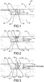
- a seal assembly 10 including an outer member 12 defining a bore 14.
- An inner member 16 is received within the bore 14 and includes an annular shoulder 18 that extends radially outward.
- the outer and inner members 12, 16 can be parts of a downhole well tool, wellhead, pipe flange connections and other applications.
- An annular backing member 20 can optionally be disposed against the annular shoulder 18 radially between the outer member 12 and the inner member 16.
- An inner ring member 22 is disposed directly radially outward and adjacent to the inner member 16 and axially adjacent to the annular backing member 20.
- An outer ring member 24 is disposed directly radially inward and adjacent to the outer member 12 and axially adjacent to the annular backing member 20 at a location directly radially outward of the inner ring member 22.
- a wedge member 26 is disposed radially at a proximate midpoint between the inner ring member 22 and outer ring member 24 and in direct contact therewith.
- An annular pressing member 28 is disposed against the wedge member 26 for providing an axial force against the wedge member 26.
- the inner ring member 22, the outer ring member 24 and the wedge member 26 can all have a circular, partial circular, partial curved or elliptical cross-section or other shape that creates a wedging effect and can be made of a metallic material such as stainless steel, carbon steel alloy, or nickel alloy.
- the inner ring member 22, the outer ring member 24 and the wedge member 26 can be made of materials such as a thermoplastic, composite or elastomer.
- the inner ring member 22, the outer ring member 24 and the wedge member 26 can be coated with a second material such as silver, thermoplastic or other materials which are softer than the sealing surface of the inner member 16 or outer member 12 to allow greater sealing performance on rough surface finishes.
- the wedge member 126 can be modified to be formed integral with the annular pressing member 128.
- the wedge member 126 can include a pair of linearly sloped driving surfaces 130a, 130b that engage the inner ring member 22 and outer ring member 24, respectively.
- the sloped driving surfaces 130a, 130b have been shown as linear surfaces, it should be understood that the driving surface 150 can be curved, as shown in the embodiment of Figure 4 .
- the wedge member 26 can be engaged by an annular pressing member 228 having a wedge-shaped recess 230 having a pair of sloped driving surfaces 232a, 232b against which the wedge member 26 is engaged.
- the wedge-shaped recess 230 helps to center the wedge member 26 in proper orientation with the inner and outer ring members 22, 24.
- the mechanical advantages provided by the seal designs of the present disclosure create very high surface contact pressures when axial force is applied to the wedge member due to the circular cross-sectional shape of the seal rings and the small contact areas at the interface of the seal rings and the sealing surfaces, allowing an effective seal to be achieved at high pressures.
- the camming effect produced by the inner and outer rings and wedge member provides the ability for the wedge ring and seal ring system to radially compensate for geometry variances due to machining imperfections, radial deformation of the mandrel or housing due to pressure effects or thermal effects.
- a component of the energizing force applied to the wedge member is pressure so that the seal system may be self-energizing.
- the sealing contact pressures will increase as differential pressure is increased across the seal system.
Landscapes
- Engineering & Computer Science (AREA)
- General Engineering & Computer Science (AREA)
- Mechanical Engineering (AREA)
- Life Sciences & Earth Sciences (AREA)
- Geology (AREA)
- Mining & Mineral Resources (AREA)
- Physics & Mathematics (AREA)
- Fluid Mechanics (AREA)
- Environmental & Geological Engineering (AREA)
- General Life Sciences & Earth Sciences (AREA)
- Geochemistry & Mineralogy (AREA)
- Gasket Seals (AREA)
Description
- The present disclosure relates to a metal to metal wedge ring seal.
- This section provides background information related to the present disclosure which is not necessarily prior art.
- When connecting adjacent sections of fluid flow conduits or vessels, seal rings are typically interposed at the interface of adjacent connecting conduits or vessel portions which are then bolted or clamped together. Most known seal rings and joints work, to a greater or lesser extent, when the pressure within the conduit, pressure vessel or the like is considerably greater than the ambient pressure outside of the conduit, pressure vessel or the like so that the seal or joint is pressure energized. A locking connector is known from document
US 2014/0130329 A1 , wherein coil springs are used to engage an inner member within the bore of an outer member. A sealing device for valves is known from United States PatentUS 4 477 057 A . Shaft seals and particularly a pressure actuated packing system for submarine periscopes are known from documentUS 2 791 194 A . Further, documentGB 830 062 A US 727 839 A a packing for the stuffing-boxes of piston-rods and the like for use with steam or water or any high pressure is known. Further, documentUS 4 462 568 A discloses a valve construction having improved seal means. - This section provides a general summary of the disclosure, and is not a comprehensive disclosure of its full scope or all of its features.
A seal assembly according to the present disclosure includes an outer member defining a bore and an inner member received in the bore of the outer member and one of the outer member and the inner member defining a shoulder portion. An inner circular cross-section metallic ring member and an outer circular cross-section metallic ring member are disposed between the outer member and inner member and against the shoulder portion. A wedge member engages the inner circular cross-section metallic ring member and the outer circular cross-section metallic ring member for applying an axial force against each of the inner and outer circular cross-section metallic ring members in a direction toward the shoulder portion and for applying a radially outer force against the outer circular cross-section metallic ring member and for applying a radially inner force against the inner circular cross-section metallic ring member. - Further areas of applicability will become apparent from the description provided herein. The description and specific examples in this summary are intended for purposes of illustration only and are not intended to limit the scope of the present disclosure.
- The drawings described herein are for illustrative purposes only of selected embodiments and not all possible implementations, and are not intended to limit the scope of the present disclosure.
-
Figure 1 is a partial cross-sectional view of a metal to metal wedge ring seal according to a first embodiment; -
Figure 2 is a partial cross-sectional view of a metal to metal wedge ring seal according to a second embodiment; -
Figure 3 is a partial cross-sectional view of a metal to metal wedge ring seal according to a third embodiment; -
Figure 4 is a partial cross-sectional view of a metal to metal wedge ring seal according to a fourth embodiment; -
Figure 5 is a partial cross-sectional view of a metal to metal wedge ring seal according to a fifth embodiment; and -
Figure 6 is a partial cross-sectional view of a metal to metal wedge ring seal according to a sixth embodiment. - Corresponding reference numerals indicate corresponding parts throughout the several views of the drawings.
- Example embodiments will now be described more fully with reference to the accompanying drawings.
- Example embodiments are provided so that this disclosure will be thorough, and will fully convey the scope to those who are skilled in the art. Numerous specific details are set forth such as examples of specific components, devices, and methods, to provide a thorough understanding of embodiments of the present disclosure. It will be apparent to those skilled in the art that specific details need not be employed, that example embodiments may be embodied in many different forms and that neither should be construed to limit the scope of the disclosure. In some example embodiments, well-known processes, well-known device structures, and well-known technologies are not described in detail.
- The terminology used herein is for the purpose of describing particular example embodiments only and is not intended to be limiting. As used herein, the singular forms "a," "an," and "the" may be intended to include the plural forms as well, unless the context clearly indicates otherwise. The terms "comprises," "comprising," "including," and "having," are inclusive and therefore specify the presence of stated features, integers, steps, operations, elements, and/or components, but do not preclude the presence or addition of one or more other features, integers, steps, operations, elements, components, and/or groups thereof. The method steps, processes, and operations described herein are not to be construed as necessarily requiring their performance in the particular order discussed or illustrated, unless specifically identified as an order of performance. It is also to be understood that additional or alternative steps may be employed.
- When an element or layer is referred to as being "on," "engaged to," "connected to," or "coupled to" another element or layer, it may be directly on, engaged, connected or coupled to the other element or layer, or intervening elements or layers may be present. In contrast, when an element is referred to as being "directly on," "directly engaged to," "directly connected to," or "directly coupled to" another element or layer, there may be no intervening elements or layers present. Other words used to describe the relationship between elements should be interpreted in a like fashion (e.g., "between" versus "directly between," "adjacent" versus "directly adjacent," etc.). As used herein, the term "and/or" includes any and all combinations of one or more of the associated listed items.
- Although the terms first, second, third, etc. may be used herein to describe various elements, components, regions, layers and/or sections, these elements, components, regions, layers and/or sections should not be limited by these terms. These terms may be only used to distinguish one element, component, region, layer or section from another region, layer or section. Terms such as "first," "second," and other numerical terms when used herein do not imply a sequence or order unless clearly indicated by the context. Thus, a first element, component, region, layer or section discussed below could be termed a second element, component, region, layer or section without departing from the teachings of the example embodiments.
- Spatially relative terms, such as "inner," "outer," "beneath," "below," "lower," "above," "upper," and the like, may be used herein for ease of description to describe one element or feature's relationship to another element(s) or feature(s) as illustrated in the figures. Spatially relative terms may be intended to encompass different orientations of the device in use or operation in addition to the orientation depicted in the figures. For example, if the device in the figures is turned over, elements described as "below" or "beneath" other elements or features would then be oriented "above" the other elements or features. Thus, the example term "below" can encompass both an orientation of above and below. The device may be otherwise oriented (rotated 90 degrees or at other orientations) and the spatially relative descriptors used herein interpreted accordingly.
- With reference to
Figure 1 , aseal assembly 10 is shown including anouter member 12 defining abore 14. Aninner member 16 is received within thebore 14 and includes anannular shoulder 18 that extends radially outward. The outer andinner members annular backing member 20 can optionally be disposed against theannular shoulder 18 radially between theouter member 12 and theinner member 16. Aninner ring member 22 is disposed directly radially outward and adjacent to theinner member 16 and axially adjacent to theannular backing member 20. Anouter ring member 24 is disposed directly radially inward and adjacent to theouter member 12 and axially adjacent to theannular backing member 20 at a location directly radially outward of theinner ring member 22. Awedge member 26 is disposed radially at a proximate midpoint between theinner ring member 22 andouter ring member 24 and in direct contact therewith. An annular pressingmember 28 is disposed against thewedge member 26 for providing an axial force against thewedge member 26. - In the embodiment shown in
Figure 1 , theinner ring member 22, theouter ring member 24 and thewedge member 26 can all have a circular, partial circular, partial curved or elliptical cross-section or other shape that creates a wedging effect and can be made of a metallic material such as stainless steel, carbon steel alloy, or nickel alloy. Alternatively, theinner ring member 22, theouter ring member 24 and thewedge member 26 can be made of materials such as a thermoplastic, composite or elastomer. Theinner ring member 22, theouter ring member 24 and thewedge member 26 can be coated with a second material such as silver, thermoplastic or other materials which are softer than the sealing surface of theinner member 16 orouter member 12 to allow greater sealing performance on rough surface finishes. - As an alternative, as shown in
Figure 2 , thewedge member 126 can be modified to be formed integral with the annular pressingmember 128. In particular, thewedge member 126 can include a pair of linearly slopeddriving surfaces inner ring member 22 andouter ring member 24, respectively. Although thesloped driving surfaces driving surface 150 can be curved, as shown in the embodiment ofFigure 4 . - As a further alternative as shown in
Figure 3 , thewedge member 26 can be engaged by an annular pressingmember 228 having a wedge-shaped recess 230 having a pair ofsloped driving surfaces wedge member 26 is engaged. The wedge-shapedrecess 230 helps to center thewedge member 26 in proper orientation with the inner andouter ring members - With reference to
Figures 5 and 6 , the seal designs ofFigure 2 and Figure 1 respectively, are shown modified to remove theannular backing member 20 so that theinner ring member 22 andouter ring member 24 are disposed directly against theannular shoulder 18 of theinner member 16. In addition, the contact surfaces of therespective wedge members inner ring member 22 andouter ring member 24 at approximately a 45° angle. - The mechanical advantages provided by the seal designs of the present disclosure create very high surface contact pressures when axial force is applied to the wedge member due to the circular cross-sectional shape of the seal rings and the small contact areas at the interface of the seal rings and the sealing surfaces, allowing an effective seal to be achieved at high pressures. The camming effect produced by the inner and outer rings and wedge member provides the ability for the wedge ring and seal ring system to radially compensate for geometry variances due to machining imperfections, radial deformation of the mandrel or housing due to pressure effects or thermal effects. In the seals of the present disclosure, a component of the energizing force applied to the wedge member is pressure so that the seal system may be self-energizing. The sealing contact pressures will increase as differential pressure is increased across the seal system.
- The foregoing description of the embodiments has been provided for purposes of illustration and description. It is not intended to be exhaustive or to limit the disclosure. Individual elements or features of a particular embodiment are generally not limited to that particular embodiment, but, where applicable, are interchangeable and can be used in a selected embodiment, even if not specifically shown or described. The same may also be varied in many ways. Such variations are not to be regarded as a departure from the disclosure, and all such modifications are intended to be included within the scope of the claims.
Claims (10)
- A seal assembly, comprising:an outer member (12) defining a bore (14);an inner member (16) received in the bore (14) of the outer member (12) and one of the outer member (12) and the inner member (16) defining a shoulder portion (18);a first circular cross section metallic ring member (22) having a first inner diameter and a first outer diameter, the first circular cross section metallic ring member (22) being disposed between the inner member (16) and the outer member (12) and directly against the inner member (16);a second circular cross section metallic ring member (24) having a second inner diameter and a second outer diameter that are larger than the first inner diameter and the first outer diameter, respectively, the second circular cross section metallic ring member (24) being disposed between the outer member (12) and the first circular cross section metallic ring member (22) and directly against the outer member (12);characterized in that:
a wedge member (26) engages the first circular cross section metallic ring member (22) and the second circular cross section metallic ring member (24) for applying an axial force against each of the first and second circular cross section metallic ring members (22, 24) in a direction toward the shoulder portion (18) and for applying a radially outer force against the second circular cross section metallic ring member (24) and for applying a radially inner force against the first circular cross section metallic ring member (22). - The seal assembly according to claim 1, wherein the wedge member (26) includes a third circular cross section metallic ring member (26) having a third inner diameter and the third outer diameter wherein the third inner diameter is larger than the first inner diameter and smaller than the second inner diameter and the third outer diameter is larger than the first outer diameter and smaller than the second outer diameter.
- The seal assembly according to claim 1, wherein the wedge member (26,126) is made from metal.
- The seal assembly according to claim 1, wherein the wedge member (126) includes an annular member having an axially protruding rib engaging the first and second circular cross section metallic ring members (22, 24).
- The seal assembly according to claim 4, wherein the axially protruding rib includes angled radially inner and radially outer surfaces (130a, 130b).
- The seal assembly according to claim 1, further comprising an annular backing member (20) disposed axially between the shoulder portion (18) and the first and second circular cross section metallic ring members (22, 24).
- The seal assembly according to claim 1, wherein the inner and outer circular cross section metallic ring members (22, 24) are coated with a second material.
- The seal assembly according to claim 1, further comprising an annular pressing member (28) disposed against the wedge member (26).
- The seal assembly according to claim 8, wherein the annular pressing member (228) includes a wedge-shaped recess (230) engaging the wedge member (26).
- The seal assembly according to claim 1, wherein the inner and outer metallic ring members have a generally circular cross-section.
Applications Claiming Priority (1)
| Application Number | Priority Date | Filing Date | Title |
|---|---|---|---|
| US15/653,075 US10309562B2 (en) | 2017-07-18 | 2017-07-18 | Metal to metal wedge ring seal |
Publications (2)
| Publication Number | Publication Date |
|---|---|
| EP3431833A1 EP3431833A1 (en) | 2019-01-23 |
| EP3431833B1 true EP3431833B1 (en) | 2020-05-13 |
Family
ID=62386124
Family Applications (1)
| Application Number | Title | Priority Date | Filing Date |
|---|---|---|---|
| EP18174328.7A Active EP3431833B1 (en) | 2017-07-18 | 2018-05-25 | Metal to metal wedge ring seal |
Country Status (3)
| Country | Link |
|---|---|
| US (1) | US10309562B2 (en) |
| EP (1) | EP3431833B1 (en) |
| CA (1) | CA3004261C (en) |
Family Cites Families (21)
| Publication number | Priority date | Publication date | Assignee | Title |
|---|---|---|---|---|
| US727839A (en) | 1903-01-31 | 1903-05-12 | Oliver Tadous Raymond | Packing. |
| US2791194A (en) | 1950-02-09 | 1957-05-07 | Janise Fabus | Submarine periscope seal |
| US2837360A (en) | 1953-08-20 | 1958-06-03 | United Aircraft Prod | Self energizing sealing ring |
| BE571631A (en) | 1957-09-30 | 1900-01-01 | ||
| FR2496217A1 (en) | 1980-12-12 | 1982-06-18 | Realisations Meca Ste Meusienn | VALVE SEALING DEVICE |
| US4462568A (en) | 1982-03-15 | 1984-07-31 | Xomox Corporation | Valve construction and method of making the same |
| US4457523A (en) | 1982-10-29 | 1984-07-03 | Pressure Science Incorporated | Torsionally flexible metallic annular seal |
| US4556224A (en) | 1984-08-06 | 1985-12-03 | Joy Manufacturing Company | Crossover seal assembly |
| FR2580764B1 (en) * | 1985-04-22 | 1987-07-10 | Bertin & Cie | HIGH PRESSURE SEALING DEVICE BETWEEN TWO RELATIVE MOVING ELEMENTS |
| GB8920607D0 (en) | 1989-09-12 | 1989-10-25 | Tri State Oil Tool Uk | Metal seal casing patch |
| US5333692A (en) | 1992-01-29 | 1994-08-02 | Baker Hughes Incorporated | Straight bore metal-to-metal wellbore seal apparatus and method of sealing in a wellbore |
| US5343946A (en) | 1993-08-09 | 1994-09-06 | Hydril Company | High pressure packer for a drop-in check valve |
| US5685369A (en) | 1996-05-01 | 1997-11-11 | Abb Vetco Gray Inc. | Metal seal well packer |
| US6705615B2 (en) | 2001-10-31 | 2004-03-16 | Dril-Quip, Inc. | Sealing system and method |
| US6983940B2 (en) | 2003-07-29 | 2006-01-10 | American Seal And Engineering Company, Inc. | Metallic seal |
| US7234533B2 (en) | 2003-10-03 | 2007-06-26 | Schlumberger Technology Corporation | Well packer having an energized sealing element and associated method |
| GB0622916D0 (en) | 2006-11-17 | 2006-12-27 | Petrowell Ltd | Improved tree plug |
| US8104769B2 (en) | 2008-12-17 | 2012-01-31 | Seal Science & Technology, Llc | Bi-directional wellhead seal |
| WO2012112823A2 (en) | 2011-02-16 | 2012-08-23 | Weatherford/Lamb, Inc. | Stage tool |
| US9829028B2 (en) | 2012-11-15 | 2017-11-28 | Bal Seal Engineering, Inc. | Connectors with a pin, a housing, and one or more springs |
| CN205331640U (en) | 2015-11-27 | 2016-06-22 | 江苏省绿岛管阀件有限公司 | PP pipe with sealed tube connects |
-
2017
- 2017-07-18 US US15/653,075 patent/US10309562B2/en active Active
-
2018
- 2018-05-08 CA CA3004261A patent/CA3004261C/en active Active
- 2018-05-25 EP EP18174328.7A patent/EP3431833B1/en active Active
Non-Patent Citations (1)
| Title |
|---|
| None * |
Also Published As
| Publication number | Publication date |
|---|---|
| CA3004261A1 (en) | 2019-01-18 |
| CA3004261C (en) | 2019-09-24 |
| EP3431833A1 (en) | 2019-01-23 |
| US10309562B2 (en) | 2019-06-04 |
| US20190024828A1 (en) | 2019-01-24 |
Similar Documents
| Publication | Publication Date | Title |
|---|---|---|
| US6869080B2 (en) | Metal-to-metal sealing system | |
| US8191933B2 (en) | Extrusion resistant gasket face seal | |
| CA2682526C (en) | Flexible seals for process control valves | |
| AU2015309042B2 (en) | Ceramic lined valve | |
| AU2020277722B2 (en) | Gasket assembly and seal carrier | |
| EP2971884B1 (en) | Composite dynamic valve seal assembly for high temperature control valves | |
| US20010045709A1 (en) | Seal ring and joint | |
| EP2971885B1 (en) | Graphite/metal valve seal assembly for high temperature control valves | |
| EP0264179A2 (en) | Improvements relating to rotary ball valves and ball joints | |
| US7604056B2 (en) | Downhole valve and method of making | |
| CN107208810A (en) | Lined Butterfly Valve | |
| CA3004261C (en) | Metal to metal wedge ring seal | |
| NO20151379A1 (en) | Improved Seal Assembly | |
| US11635142B2 (en) | Dual barrier seal | |
| US4909548A (en) | Compound-taper flange assembly | |
| EP2472159A1 (en) | Flange seal | |
| GB2558001A (en) | Seal ring and joint | |
| US20030080516A1 (en) | Fluid seal and method of using same | |
| EP4374043B1 (en) | Bi-directional seal element and sealing system | |
| US20250283534A1 (en) | Metallic Dynamic Seal | |
| WO2018100022A1 (en) | Flange coupling | |
| GB2194315A (en) | Rotary ball valves and ball joints |
Legal Events
| Date | Code | Title | Description |
|---|---|---|---|
| PUAI | Public reference made under article 153(3) epc to a published international application that has entered the european phase |
Free format text: ORIGINAL CODE: 0009012 |
|
| STAA | Information on the status of an ep patent application or granted ep patent |
Free format text: STATUS: REQUEST FOR EXAMINATION WAS MADE |
|
| 17P | Request for examination filed |
Effective date: 20180621 |
|
| AK | Designated contracting states |
Kind code of ref document: A1 Designated state(s): AL AT BE BG CH CY CZ DE DK EE ES FI FR GB GR HR HU IE IS IT LI LT LU LV MC MK MT NL NO PL PT RO RS SE SI SK SM TR |
|
| AX | Request for extension of the european patent |
Extension state: BA ME |
|
| STAA | Information on the status of an ep patent application or granted ep patent |
Free format text: STATUS: EXAMINATION IS IN PROGRESS |
|
| 17Q | First examination report despatched |
Effective date: 20190827 |
|
| GRAJ | Information related to disapproval of communication of intention to grant by the applicant or resumption of examination proceedings by the epo deleted |
Free format text: ORIGINAL CODE: EPIDOSDIGR1 |
|
| STAA | Information on the status of an ep patent application or granted ep patent |
Free format text: STATUS: GRANT OF PATENT IS INTENDED |
|
| GRAP | Despatch of communication of intention to grant a patent |
Free format text: ORIGINAL CODE: EPIDOSNIGR1 |
|
| INTG | Intention to grant announced |
Effective date: 20200214 |
|
| GRAS | Grant fee paid |
Free format text: ORIGINAL CODE: EPIDOSNIGR3 |
|
| GRAA | (expected) grant |
Free format text: ORIGINAL CODE: 0009210 |
|
| STAA | Information on the status of an ep patent application or granted ep patent |
Free format text: STATUS: THE PATENT HAS BEEN GRANTED |
|
| AK | Designated contracting states |
Kind code of ref document: B1 Designated state(s): AL AT BE BG CH CY CZ DE DK EE ES FI FR GB GR HR HU IE IS IT LI LT LU LV MC MK MT NL NO PL PT RO RS SE SI SK SM TR |
|
| REG | Reference to a national code |
Ref country code: GB Ref legal event code: FG4D |
|
| REG | Reference to a national code |
Ref country code: CH Ref legal event code: EP |
|
| REG | Reference to a national code |
Ref country code: DE Ref legal event code: R096 Ref document number: 602018004401 Country of ref document: DE |
|
| REG | Reference to a national code |
Ref country code: AT Ref legal event code: REF Ref document number: 1270712 Country of ref document: AT Kind code of ref document: T Effective date: 20200615 |
|
| REG | Reference to a national code |
Ref country code: LT Ref legal event code: MG4D Ref country code: NO Ref legal event code: T2 Effective date: 20200513 |
|
| REG | Reference to a national code |
Ref country code: NL Ref legal event code: MP Effective date: 20200513 |
|
| PG25 | Lapsed in a contracting state [announced via postgrant information from national office to epo] |
Ref country code: GR Free format text: LAPSE BECAUSE OF FAILURE TO SUBMIT A TRANSLATION OF THE DESCRIPTION OR TO PAY THE FEE WITHIN THE PRESCRIBED TIME-LIMIT Effective date: 20200814 Ref country code: FI Free format text: LAPSE BECAUSE OF FAILURE TO SUBMIT A TRANSLATION OF THE DESCRIPTION OR TO PAY THE FEE WITHIN THE PRESCRIBED TIME-LIMIT Effective date: 20200513 Ref country code: PT Free format text: LAPSE BECAUSE OF FAILURE TO SUBMIT A TRANSLATION OF THE DESCRIPTION OR TO PAY THE FEE WITHIN THE PRESCRIBED TIME-LIMIT Effective date: 20200914 Ref country code: LT Free format text: LAPSE BECAUSE OF FAILURE TO SUBMIT A TRANSLATION OF THE DESCRIPTION OR TO PAY THE FEE WITHIN THE PRESCRIBED TIME-LIMIT Effective date: 20200513 Ref country code: SE Free format text: LAPSE BECAUSE OF FAILURE TO SUBMIT A TRANSLATION OF THE DESCRIPTION OR TO PAY THE FEE WITHIN THE PRESCRIBED TIME-LIMIT Effective date: 20200513 Ref country code: IS Free format text: LAPSE BECAUSE OF FAILURE TO SUBMIT A TRANSLATION OF THE DESCRIPTION OR TO PAY THE FEE WITHIN THE PRESCRIBED TIME-LIMIT Effective date: 20200913 |
|
| PG25 | Lapsed in a contracting state [announced via postgrant information from national office to epo] |
Ref country code: BG Free format text: LAPSE BECAUSE OF FAILURE TO SUBMIT A TRANSLATION OF THE DESCRIPTION OR TO PAY THE FEE WITHIN THE PRESCRIBED TIME-LIMIT Effective date: 20200813 Ref country code: RS Free format text: LAPSE BECAUSE OF FAILURE TO SUBMIT A TRANSLATION OF THE DESCRIPTION OR TO PAY THE FEE WITHIN THE PRESCRIBED TIME-LIMIT Effective date: 20200513 Ref country code: HR Free format text: LAPSE BECAUSE OF FAILURE TO SUBMIT A TRANSLATION OF THE DESCRIPTION OR TO PAY THE FEE WITHIN THE PRESCRIBED TIME-LIMIT Effective date: 20200513 Ref country code: LV Free format text: LAPSE BECAUSE OF FAILURE TO SUBMIT A TRANSLATION OF THE DESCRIPTION OR TO PAY THE FEE WITHIN THE PRESCRIBED TIME-LIMIT Effective date: 20200513 |
|
| REG | Reference to a national code |
Ref country code: AT Ref legal event code: MK05 Ref document number: 1270712 Country of ref document: AT Kind code of ref document: T Effective date: 20200513 |
|
| PG25 | Lapsed in a contracting state [announced via postgrant information from national office to epo] |
Ref country code: NL Free format text: LAPSE BECAUSE OF FAILURE TO SUBMIT A TRANSLATION OF THE DESCRIPTION OR TO PAY THE FEE WITHIN THE PRESCRIBED TIME-LIMIT Effective date: 20200513 Ref country code: AL Free format text: LAPSE BECAUSE OF FAILURE TO SUBMIT A TRANSLATION OF THE DESCRIPTION OR TO PAY THE FEE WITHIN THE PRESCRIBED TIME-LIMIT Effective date: 20200513 |
|
| PG25 | Lapsed in a contracting state [announced via postgrant information from national office to epo] |
Ref country code: ES Free format text: LAPSE BECAUSE OF FAILURE TO SUBMIT A TRANSLATION OF THE DESCRIPTION OR TO PAY THE FEE WITHIN THE PRESCRIBED TIME-LIMIT Effective date: 20200513 Ref country code: AT Free format text: LAPSE BECAUSE OF FAILURE TO SUBMIT A TRANSLATION OF THE DESCRIPTION OR TO PAY THE FEE WITHIN THE PRESCRIBED TIME-LIMIT Effective date: 20200513 Ref country code: DK Free format text: LAPSE BECAUSE OF FAILURE TO SUBMIT A TRANSLATION OF THE DESCRIPTION OR TO PAY THE FEE WITHIN THE PRESCRIBED TIME-LIMIT Effective date: 20200513 Ref country code: CZ Free format text: LAPSE BECAUSE OF FAILURE TO SUBMIT A TRANSLATION OF THE DESCRIPTION OR TO PAY THE FEE WITHIN THE PRESCRIBED TIME-LIMIT Effective date: 20200513 Ref country code: EE Free format text: LAPSE BECAUSE OF FAILURE TO SUBMIT A TRANSLATION OF THE DESCRIPTION OR TO PAY THE FEE WITHIN THE PRESCRIBED TIME-LIMIT Effective date: 20200513 Ref country code: RO Free format text: LAPSE BECAUSE OF FAILURE TO SUBMIT A TRANSLATION OF THE DESCRIPTION OR TO PAY THE FEE WITHIN THE PRESCRIBED TIME-LIMIT Effective date: 20200513 Ref country code: IT Free format text: LAPSE BECAUSE OF FAILURE TO SUBMIT A TRANSLATION OF THE DESCRIPTION OR TO PAY THE FEE WITHIN THE PRESCRIBED TIME-LIMIT Effective date: 20200513 Ref country code: SM Free format text: LAPSE BECAUSE OF FAILURE TO SUBMIT A TRANSLATION OF THE DESCRIPTION OR TO PAY THE FEE WITHIN THE PRESCRIBED TIME-LIMIT Effective date: 20200513 |
|
| REG | Reference to a national code |
Ref country code: DE Ref legal event code: R097 Ref document number: 602018004401 Country of ref document: DE |
|
| PG25 | Lapsed in a contracting state [announced via postgrant information from national office to epo] |
Ref country code: MC Free format text: LAPSE BECAUSE OF FAILURE TO SUBMIT A TRANSLATION OF THE DESCRIPTION OR TO PAY THE FEE WITHIN THE PRESCRIBED TIME-LIMIT Effective date: 20200513 Ref country code: SK Free format text: LAPSE BECAUSE OF FAILURE TO SUBMIT A TRANSLATION OF THE DESCRIPTION OR TO PAY THE FEE WITHIN THE PRESCRIBED TIME-LIMIT Effective date: 20200513 Ref country code: PL Free format text: LAPSE BECAUSE OF FAILURE TO SUBMIT A TRANSLATION OF THE DESCRIPTION OR TO PAY THE FEE WITHIN THE PRESCRIBED TIME-LIMIT Effective date: 20200513 |
|
| PLBE | No opposition filed within time limit |
Free format text: ORIGINAL CODE: 0009261 |
|
| REG | Reference to a national code |
Ref country code: BE Ref legal event code: MM Effective date: 20200531 |
|
| STAA | Information on the status of an ep patent application or granted ep patent |
Free format text: STATUS: NO OPPOSITION FILED WITHIN TIME LIMIT |
|
| PG25 | Lapsed in a contracting state [announced via postgrant information from national office to epo] |
Ref country code: LU Free format text: LAPSE BECAUSE OF NON-PAYMENT OF DUE FEES Effective date: 20200525 |
|
| 26N | No opposition filed |
Effective date: 20210216 |
|
| PG25 | Lapsed in a contracting state [announced via postgrant information from national office to epo] |
Ref country code: IE Free format text: LAPSE BECAUSE OF NON-PAYMENT OF DUE FEES Effective date: 20200525 Ref country code: FR Free format text: LAPSE BECAUSE OF NON-PAYMENT OF DUE FEES Effective date: 20200713 |
|
| PG25 | Lapsed in a contracting state [announced via postgrant information from national office to epo] |
Ref country code: BE Free format text: LAPSE BECAUSE OF NON-PAYMENT OF DUE FEES Effective date: 20200531 Ref country code: SI Free format text: LAPSE BECAUSE OF FAILURE TO SUBMIT A TRANSLATION OF THE DESCRIPTION OR TO PAY THE FEE WITHIN THE PRESCRIBED TIME-LIMIT Effective date: 20200513 |
|
| REG | Reference to a national code |
Ref country code: CH Ref legal event code: PL |
|
| PG25 | Lapsed in a contracting state [announced via postgrant information from national office to epo] |
Ref country code: CH Free format text: LAPSE BECAUSE OF NON-PAYMENT OF DUE FEES Effective date: 20210531 Ref country code: LI Free format text: LAPSE BECAUSE OF NON-PAYMENT OF DUE FEES Effective date: 20210531 |
|
| PG25 | Lapsed in a contracting state [announced via postgrant information from national office to epo] |
Ref country code: TR Free format text: LAPSE BECAUSE OF FAILURE TO SUBMIT A TRANSLATION OF THE DESCRIPTION OR TO PAY THE FEE WITHIN THE PRESCRIBED TIME-LIMIT Effective date: 20200513 Ref country code: MT Free format text: LAPSE BECAUSE OF FAILURE TO SUBMIT A TRANSLATION OF THE DESCRIPTION OR TO PAY THE FEE WITHIN THE PRESCRIBED TIME-LIMIT Effective date: 20200513 Ref country code: CY Free format text: LAPSE BECAUSE OF FAILURE TO SUBMIT A TRANSLATION OF THE DESCRIPTION OR TO PAY THE FEE WITHIN THE PRESCRIBED TIME-LIMIT Effective date: 20200513 |
|
| PG25 | Lapsed in a contracting state [announced via postgrant information from national office to epo] |
Ref country code: MK Free format text: LAPSE BECAUSE OF FAILURE TO SUBMIT A TRANSLATION OF THE DESCRIPTION OR TO PAY THE FEE WITHIN THE PRESCRIBED TIME-LIMIT Effective date: 20200513 |
|
| P01 | Opt-out of the competence of the unified patent court (upc) registered |
Effective date: 20230515 |
|
| REG | Reference to a national code |
Ref country code: DE Ref legal event code: R081 Ref document number: 602018004401 Country of ref document: DE Owner name: FREUDENBERG FLOW TECHNOLOGIES LLC (N.D.GES.D.S, US Free format text: FORMER OWNER: FREUDENBERG OIL & GAS, LLC, HOUSTON, TEX., US |
|
| PGFP | Annual fee paid to national office [announced via postgrant information from national office to epo] |
Ref country code: GB Payment date: 20260527 Year of fee payment: 9 |
|
| PGFP | Annual fee paid to national office [announced via postgrant information from national office to epo] |
Ref country code: DE Payment date: 20260602 Year of fee payment: 9 |
|
| PGFP | Annual fee paid to national office [announced via postgrant information from national office to epo] |
Ref country code: NO Payment date: 20260521 Year of fee payment: 9 |