EP3431821A1 - Planet gear having failure mode optimized for continued planetary gear system operation - Google Patents
Planet gear having failure mode optimized for continued planetary gear system operation Download PDFInfo
- Publication number
- EP3431821A1 EP3431821A1 EP17186844.1A EP17186844A EP3431821A1 EP 3431821 A1 EP3431821 A1 EP 3431821A1 EP 17186844 A EP17186844 A EP 17186844A EP 3431821 A1 EP3431821 A1 EP 3431821A1
- Authority
- EP
- European Patent Office
- Prior art keywords
- planet gear
- rim
- gear
- planet
- planetary gear
- Prior art date
- Legal status (The legal status is an assumption and is not a legal conclusion. Google has not performed a legal analysis and makes no representation as to the accuracy of the status listed.)
- Granted
Links
Images

Classifications
-
- F—MECHANICAL ENGINEERING; LIGHTING; HEATING; WEAPONS; BLASTING
- F16—ENGINEERING ELEMENTS AND UNITS; GENERAL MEASURES FOR PRODUCING AND MAINTAINING EFFECTIVE FUNCTIONING OF MACHINES OR INSTALLATIONS; THERMAL INSULATION IN GENERAL
- F16H—GEARING
- F16H1/00—Toothed gearings for conveying rotary motion
- F16H1/28—Toothed gearings for conveying rotary motion with gears having orbital motion
- F16H1/32—Toothed gearings for conveying rotary motion with gears having orbital motion in which the central axis of the gearing lies inside the periphery of an orbital gear
-
- F—MECHANICAL ENGINEERING; LIGHTING; HEATING; WEAPONS; BLASTING
- F16—ENGINEERING ELEMENTS AND UNITS; GENERAL MEASURES FOR PRODUCING AND MAINTAINING EFFECTIVE FUNCTIONING OF MACHINES OR INSTALLATIONS; THERMAL INSULATION IN GENERAL
- F16H—GEARING
- F16H57/00—General details of gearing
- F16H57/08—General details of gearing of gearings with members having orbital motion
-
- F—MECHANICAL ENGINEERING; LIGHTING; HEATING; WEAPONS; BLASTING
- F16—ENGINEERING ELEMENTS AND UNITS; GENERAL MEASURES FOR PRODUCING AND MAINTAINING EFFECTIVE FUNCTIONING OF MACHINES OR INSTALLATIONS; THERMAL INSULATION IN GENERAL
- F16H—GEARING
- F16H1/00—Toothed gearings for conveying rotary motion
- F16H1/28—Toothed gearings for conveying rotary motion with gears having orbital motion
-
- F—MECHANICAL ENGINEERING; LIGHTING; HEATING; WEAPONS; BLASTING
- F16—ENGINEERING ELEMENTS AND UNITS; GENERAL MEASURES FOR PRODUCING AND MAINTAINING EFFECTIVE FUNCTIONING OF MACHINES OR INSTALLATIONS; THERMAL INSULATION IN GENERAL
- F16H—GEARING
- F16H55/00—Elements with teeth or friction surfaces for conveying motion; Worms, pulleys or sheaves for gearing mechanisms
- F16H55/02—Toothed members; Worms
- F16H55/08—Profiling
-
- F—MECHANICAL ENGINEERING; LIGHTING; HEATING; WEAPONS; BLASTING
- F16—ENGINEERING ELEMENTS AND UNITS; GENERAL MEASURES FOR PRODUCING AND MAINTAINING EFFECTIVE FUNCTIONING OF MACHINES OR INSTALLATIONS; THERMAL INSULATION IN GENERAL
- F16H—GEARING
- F16H55/00—Elements with teeth or friction surfaces for conveying motion; Worms, pulleys or sheaves for gearing mechanisms
- F16H55/02—Toothed members; Worms
- F16H55/17—Toothed wheels
-
- F—MECHANICAL ENGINEERING; LIGHTING; HEATING; WEAPONS; BLASTING
- F16—ENGINEERING ELEMENTS AND UNITS; GENERAL MEASURES FOR PRODUCING AND MAINTAINING EFFECTIVE FUNCTIONING OF MACHINES OR INSTALLATIONS; THERMAL INSULATION IN GENERAL
- F16H—GEARING
- F16H57/00—General details of gearing
- F16H57/08—General details of gearing of gearings with members having orbital motion
- F16H57/082—Planet carriers
-
- G—PHYSICS
- G01—MEASURING; TESTING
- G01M—TESTING STATIC OR DYNAMIC BALANCE OF MACHINES OR STRUCTURES; TESTING OF STRUCTURES OR APPARATUS, NOT OTHERWISE PROVIDED FOR
- G01M13/00—Testing of machine parts
- G01M13/02—Gearings; Transmission mechanisms
- G01M13/021—Gearings
-
- F—MECHANICAL ENGINEERING; LIGHTING; HEATING; WEAPONS; BLASTING
- F16—ENGINEERING ELEMENTS AND UNITS; GENERAL MEASURES FOR PRODUCING AND MAINTAINING EFFECTIVE FUNCTIONING OF MACHINES OR INSTALLATIONS; THERMAL INSULATION IN GENERAL
- F16H—GEARING
- F16H1/00—Toothed gearings for conveying rotary motion
- F16H1/28—Toothed gearings for conveying rotary motion with gears having orbital motion
- F16H1/32—Toothed gearings for conveying rotary motion with gears having orbital motion in which the central axis of the gearing lies inside the periphery of an orbital gear
- F16H2001/327—Toothed gearings for conveying rotary motion with gears having orbital motion in which the central axis of the gearing lies inside the periphery of an orbital gear with the orbital gear having internal gear teeth
-
- F—MECHANICAL ENGINEERING; LIGHTING; HEATING; WEAPONS; BLASTING
- F16—ENGINEERING ELEMENTS AND UNITS; GENERAL MEASURES FOR PRODUCING AND MAINTAINING EFFECTIVE FUNCTIONING OF MACHINES OR INSTALLATIONS; THERMAL INSULATION IN GENERAL
- F16H—GEARING
- F16H57/00—General details of gearing
- F16H2057/0087—Computer aided design [CAD] specially adapted for gearing features; Analysis of gear systems
Definitions
- a planet gear or a pinion gear is typically designed to fail by gear tooth breakage.
- the planetary gear system can experience a catastrophic failure when the broken tooth remnants become enmeshed between planet gears and the sun gear and/or between the planet gears and the ring gear.
- This failure mode can cause the planet teeth or pinion teeth to catastrophically lock up due to interference with the mating teeth of the sun gear or ring gear.
- a catastrophic failure of a planetary gear system in some applications may be an expensive inconvenience, such a failure in an aircraft propulsion system, such as, but not limited to, the propulsion system of a helicopter, can lead to fatal crashes and/or significant damage to the aircraft.
- some studies nonetheless champion the promotion of planet gear tooth breakage as a preferred, primary, and desired failure mode of the planet gears.
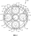
- the planetary gear system 100 comprises a sun gear 102, a ring gear 104, and four planet gears 106 (or pinion gears).
- the four planet gears 106 are carried by a carrier 108. More specifically, the planet gears 106 are rotatably mounted to posts 110 of the carrier 108 using roller bearings 112.
- the planetary gear system 100 can be driven in multiple ways by restricting angular rotation of any one of the sun gear 102, ring gear 104, and the carrier 108, operation of the planetary gear system 100 is described herein for illustration purposes as allowing angular rotation of the sun gear 102 and the carrier 108 about a central axis 114 of a shaft 116 to which the sun gear 102 is mounted. Most generally, with the carrier 108 prevented from rotating about the central axis 114, a clockwise rotation of the shaft 116 and associated sun gear 102 results in the counter-clockwise rotation of the planet gears 106 and clockwise rotation of the carrier 108.
- each of the sun gear 102, the ring gear 104, and the planet gears 106 are formed as involute gears so that, when functioning under normal operating conditions and without failure of any of the gears, contact between two gear teeth occurs along a single line of action (or pressure line or line of contact).
- conventional planetary gear system are designed with a preference toward breaking teeth off planet gears as a primary mode of failure
- the planetary gear system 100 is designed to accommodate a break 122 in a rim 118 of a planet gear 106.
- the rims 118 can most generally be described as comprising the material of the planet gears 106 that exists radially inward (toward the associated posts 110) from the root circle (comprising a root diameter) of the planet gears 106. More generally, the rims 118 comprise the material of the planet gears 106 that carry planet gear teeth 120.
- the planetary gear system 100 is shown with a break 122 (or a through crack).
- the break 122 rotates counter-clockwise about the associated post 110.
- the break 122 has passed engagement of the teeth of the sun gear 102 and is approaching the ring gear 104
- the ends of the broken rim 118 are in compression so that the broken planet gear 106 generally behaves normally and is not significantly distorted or out of round.
- the break 122 has passed engagement with the teeth of the ring gear 104 and is approaching the sun gear 102
- the forces applied to the broken planet gear 106 by the sun gear 102 and the ring gear 104 tend to separate the ends of the broken rim 118.
- the rim 118 is forced out of round so that the portion of the rim 118 from the break 122 to the interface between the broken planet gear 106 and the ring gear 104 is distorted and may be partially elastically unfurled and/or partially straightened relative to the original circular shape of the rim 118. Even though the unfurling may only be temporary due to the at least partially elastic nature of the bending, the unfurling may alter the meshing characteristics of the planet gear 106 relative to the ring gear 104.
- the planetary gear system 100 of the present disclosure is designed so that the unfurling is anticipated and accommodated in the size and shape of the planet gear teeth 120 and/or the ring gear teeth 124 of the ring gear 104 and/or the sun gear teeth 125.
- the planet gears 106 are purposefully designed and optimized to more probably fail by rim 118 breakage as opposed to planet gear tooth 120 fracture. Accordingly, at least in part because the planet gears 106 do not shed planet gear teeth 120 into the planetary gear system 100, an at least temporarily benign failure mode of the planet gears 106 and associated planetary gear system 100 can be obtained.
- Providing planetary gear system 100 with the above-described planet gears 106 configured to ensure formation of a break 122 rather than planet gear tooth 120 breakage can be accomplished in a variety of ways.
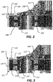
- FIG 2 a cutaway view of a conventional planet gear 200 is shown.
- the planet gear 200 is generally designed to comprises a primary failure mode of planet gear tooth 202 breakage.
- the resultant potentially destructive result of casting planet gear tooth 202 fragments into the remainder of a planetary gear system is highly undesirable.
- the planet gear comprises a rim thickness 204 and a planet gear tooth 202 depth 206.
- the planet gear 200 comprises a backup ratio of 2.0 (calculated as rim thickness 204 divided by planet gear tooth 202 depth 206).
- the planet gear 200 is associated with roller bearings 208 comprising an 11 millimeter diameter and an 11 millimeter length. The roller bearings 208 assist with allowing rotation of the planet gear 200 about a post 210 of a carrier 212.
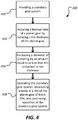
- Planet gear 106 is substantially similar to planet gear 200, however, planet gear 106 has been optimized to promote rim 118 cracking and/or breakage rather than planet gear 106 tooth 120 breakage. More specifically, the planet gear 106 has been optimized relative to the conventional planet gear 200 by reducing the backup ratio of the planet gear 106 relative to the backup ratio of the conventional planet gear 200. In this embodiment, the backup ratio of the planet gear is 1.65 (calculated as rim thickness 119 divided by planet gear 106 tooth 120 depth 121).
- the reduction in thickness of the rim 118 can provide an opportunity for larger bearings 112 without increasing an overall diameter of the planet gear 106.
- Figure 3 demonstrates that a conventional planet gear can be optimized to both promote rim cracking and/or breakage rather than planet gear tooth breakage.
- the optimization allows for relatively larger roller bearings 112 comprising a 13 millimeter diameter and a 13 millimeter length.
- a planet gear may be optimized by providing a rim thickness equal to about 0.5 to about 1.2 times the tooth depth so that a majority of root cracks propagate through the rim 118 to form a break 122.
- a planet gear can be optimized to promote rim cracking by reducing the backup ratio as a function of increasing a tooth depth while maintaining an existing rim thickness.
- a planet gear can be optimized to promote rim cracking by both increasing a tooth depth and reducing a rim thickness.
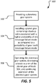
- the method 400 may begin at block 402 by providing a planetary gear system.
- the providing the planetary gear system may comprise providing an initially conventionally designed planetary gear system comprising planet gears designed to fail by tooth breakage.
- the method 400 may continue at block 404 by reducing a backup ratio of a planet gear by reducing a rim thickness of the planet gear.
- the conventional planet gear can be supplanted by a planet gear comprising the desired reduced backup ratio while in other cases, an existing conventional planet gear may be machined to reduce the thickness of the planet gear rim.
- the method 400 can continue at block 406 by increasing a diameter of a bearing by an amount equal to or less than the reduction in planet gear rim thickness accomplished at block 404.
- the method 400 may continue at block 408 by operating the planetary gear system, developing a break in a rim of the planet gear of block 404, and continuing operation of the planetary gear system.
- the continuing operation of the planetary gear system may comprise the above-described at least partial unfurling of the rim of the planet gear of block 404.
- the method 500 may begin at block 502 by providing a planetary gear system.
- the providing the planetary gear system may comprise providing an initially conventionally designed planetary gear system comprising planet gears designed to fail by tooth breakage.
- the method 500 may continue at block 504 by installing a planet gear comprising a backup ratio associated with a higher probability of rim breakage failure mode as compared to a probability of gear tooth breakage failure mode. In some embodiments, this may comprise installing a planet gear comprising a rim thickness of about 0.5 to about 1.2 times the tooth depth of the planet gear.
- the method 500 may continue at block 506 by operating the planetary gear system, developing a break in a rim of the planet gear of block 504, and continuing operation of the planetary gear system.
- the continuing operation of the planetary gear system may comprise the above-described at least partial unfurling of the rim of the planet gear of block 504.
- the method 600 may begin at block 602 by establishing a value for either a planet gear rim thickness or a planet gear tooth depth.
- the method 600 can continue at block 604 by, as a function of the value established at block 602, establishing a value for the yet unestablished one of the planet gear rim thickness and planet gear tooth depth to provide a backup ratio associated with a higher probability of a rim breakage failure mode as compared to a probability of a tooth breakage failure mode.
- the method may continue at block 606 by constructing a planet gear comprising the established values and installing the planet gear to a planetary gear system.
- R l a numerical range with a lower limit, R l , and an upper limit, R u .
- R l any number falling within the range is specifically disclosed.
- any numerical range defined by two R numbers as defined in the above is also specifically disclosed.
Landscapes
- Engineering & Computer Science (AREA)
- General Engineering & Computer Science (AREA)
- Mechanical Engineering (AREA)
- Physics & Mathematics (AREA)
- General Physics & Mathematics (AREA)
- Retarders (AREA)
Abstract
Description
- In planetary gear systems, a planet gear or a pinion gear is typically designed to fail by gear tooth breakage. In cases where a planet gear tooth breaks off from the planet gear, the planetary gear system can experience a catastrophic failure when the broken tooth remnants become enmeshed between planet gears and the sun gear and/or between the planet gears and the ring gear. This failure mode can cause the planet teeth or pinion teeth to catastrophically lock up due to interference with the mating teeth of the sun gear or ring gear. While a catastrophic failure of a planetary gear system in some applications may be an expensive inconvenience, such a failure in an aircraft propulsion system, such as, but not limited to, the propulsion system of a helicopter, can lead to fatal crashes and/or significant damage to the aircraft. Despite these concerns, some studies nonetheless champion the promotion of planet gear tooth breakage as a preferred, primary, and desired failure mode of the planet gears.
-
-
Figure 1 is an orthogonal top view of a planetary gear system according to an embodiment of this disclosure. -
Figure 2 is a cutaway view of a conventional planet gear. -
Figure 3 is a cutaway view of a planet gear of the present disclosure. -
Figure 4 is a flowchart of a method of optimizing a planetary gear system for continued operation after failure of a planet gear. -
Figure 5 is a flowchart of another method of optimizing a planetary gear system for continued operation after failure of a planet gear. -
Figure 6 is a flowchart of a method of optimizing a planet gear for rim breakage rather than tooth breakage. - In the specification, reference may be made to the spatial relationships between various components and to the spatial orientation of various aspects of components as the devices are depicted in the attached drawings. However, as will be recognized by those skilled in the art after a complete reading of the present disclosure, the devices, members, apparatuses, etc. described herein may be positioned in any desired orientation. Thus, the use of terms such as "above," "below," "upper," "lower," or other like terms to describe a spatial relationship between various components or to describe the spatial orientation of aspects of such components should be understood to describe a relative relationship between the components or a spatial orientation of aspects of such components, respectively, as the device described herein may be oriented in any desired direction.
- Referring now to
Figure 1 , aplanetary gear system 100 of the present disclosure is shown. Theplanetary gear system 100 comprises asun gear 102, aring gear 104, and four planet gears 106 (or pinion gears). The fourplanet gears 106 are carried by acarrier 108. More specifically, theplanet gears 106 are rotatably mounted toposts 110 of thecarrier 108 usingroller bearings 112. Although theplanetary gear system 100 can be driven in multiple ways by restricting angular rotation of any one of thesun gear 102,ring gear 104, and thecarrier 108, operation of theplanetary gear system 100 is described herein for illustration purposes as allowing angular rotation of thesun gear 102 and thecarrier 108 about acentral axis 114 of ashaft 116 to which thesun gear 102 is mounted. Most generally, with thecarrier 108 prevented from rotating about thecentral axis 114, a clockwise rotation of theshaft 116 and associatedsun gear 102 results in the counter-clockwise rotation of theplanet gears 106 and clockwise rotation of thecarrier 108. In this embodiment, each of thesun gear 102, thering gear 104, and theplanet gears 106 are formed as involute gears so that, when functioning under normal operating conditions and without failure of any of the gears, contact between two gear teeth occurs along a single line of action (or pressure line or line of contact). While conventional planetary gear system are designed with a preference toward breaking teeth off planet gears as a primary mode of failure, theplanetary gear system 100 is designed to accommodate abreak 122 in arim 118 of aplanet gear 106. Therims 118 can most generally be described as comprising the material of theplanet gears 106 that exists radially inward (toward the associated posts 110) from the root circle (comprising a root diameter) of theplanet gears 106. More generally, therims 118 comprise the material of theplanet gears 106 that carryplanet gear teeth 120. - Still referring to
Figure 1 , theplanetary gear system 100 is shown with a break 122 (or a through crack). When theplanetary gear system 100 operates as described with respect toFigure 1 , thebreak 122 rotates counter-clockwise about the associatedpost 110. When thebreak 122 has passed engagement of the teeth of thesun gear 102 and is approaching thering gear 104, the ends of thebroken rim 118 are in compression so that thebroken planet gear 106 generally behaves normally and is not significantly distorted or out of round. However, when thebreak 122 has passed engagement with the teeth of thering gear 104 and is approaching thesun gear 102, the forces applied to thebroken planet gear 106 by thesun gear 102 and thering gear 104 tend to separate the ends of thebroken rim 118. As a function of the separation, therim 118 is forced out of round so that the portion of therim 118 from thebreak 122 to the interface between thebroken planet gear 106 and thering gear 104 is distorted and may be partially elastically unfurled and/or partially straightened relative to the original circular shape of therim 118. Even though the unfurling may only be temporary due to the at least partially elastic nature of the bending, the unfurling may alter the meshing characteristics of theplanet gear 106 relative to thering gear 104. While high contact ratio planetary gear systems with relatively longer teeth may experience binding or tooth interference between thebroken planet gear 106 and thering gear 104 or thesun gear 102, theplanetary gear system 100 of the present disclosure is designed so that the unfurling is anticipated and accommodated in the size and shape of theplanet gear teeth 120 and/or thering gear teeth 124 of thering gear 104 and/or thesun gear teeth 125. In order to provide aplanet gear 106 failure mode, such asrim 118break 122 rather than breaking off aplanet gear tooth 120, theplanet gears 106 are purposefully designed and optimized to more probably fail byrim 118 breakage as opposed toplanet gear tooth 120 fracture. Accordingly, at least in part because theplanet gears 106 do not shedplanet gear teeth 120 into theplanetary gear system 100, an at least temporarily benign failure mode of theplanet gears 106 and associatedplanetary gear system 100 can be obtained. - Providing
planetary gear system 100 with the above-describedplanet gears 106 configured to ensure formation of abreak 122 rather thanplanet gear tooth 120 breakage can be accomplished in a variety of ways. Referring now toFigure 2 , a cutaway view of aconventional planet gear 200 is shown. Theplanet gear 200 is generally designed to comprises a primary failure mode ofplanet gear tooth 202 breakage. However, as described above, the resultant potentially destructive result of castingplanet gear tooth 202 fragments into the remainder of a planetary gear system is highly undesirable. More specifically, in the conventional embodiment shown inFigure 2 , the planet gear comprises arim thickness 204 and aplanet gear tooth 202 depth 206. In this embodiment, theplanet gear 200 comprises a backup ratio of 2.0 (calculated asrim thickness 204 divided byplanet gear tooth 202 depth 206). In this embodiment, theplanet gear 200 is associated withroller bearings 208 comprising an 11 millimeter diameter and an 11 millimeter length. Theroller bearings 208 assist with allowing rotation of theplanet gear 200 about apost 210 of acarrier 212. - Referring now to
Figure 3 , a cutaway view ofplanet gear 106 according to the present disclosure is shown. Planetgear 106 is substantially similar toplanet gear 200, however,planet gear 106 has been optimized to promote rim 118 cracking and/or breakage rather thanplanet gear 106tooth 120 breakage. More specifically, theplanet gear 106 has been optimized relative to theconventional planet gear 200 by reducing the backup ratio of theplanet gear 106 relative to the backup ratio of theconventional planet gear 200. In this embodiment, the backup ratio of the planet gear is 1.65 (calculated asrim thickness 119 divided byplanet gear 106tooth 120 depth 121). In addition to preventingtooth 120 breakage or at least reducing a probability oftooth 120 breakage prior to formation of abreak 122, the reduction in thickness of therim 118 can provide an opportunity forlarger bearings 112 without increasing an overall diameter of theplanet gear 106. In other words, by thinning therim 118 and substantially holding otherplanetary gear system 100 dimensions constant (but for bearing 112 size),Figure 3 demonstrates that a conventional planet gear can be optimized to both promote rim cracking and/or breakage rather than planet gear tooth breakage. In this embodiment, the optimization (reducedrim 118 thickness 119) allows for relativelylarger roller bearings 112 comprising a 13 millimeter diameter and a 13 millimeter length. In some alternative embodiments, a planet gear may be optimized by providing a rim thickness equal to about 0.5 to about 1.2 times the tooth depth so that a majority of root cracks propagate through therim 118 to form abreak 122. In alternative embodiments, a planet gear can be optimized to promote rim cracking by reducing the backup ratio as a function of increasing a tooth depth while maintaining an existing rim thickness. Still further, in other embodiments, a planet gear can be optimized to promote rim cracking by both increasing a tooth depth and reducing a rim thickness. - Referring now to
Figure 4 , a flowchart of amethod 400 of optimizing a planetary gear system for continued operation after failure of a planet gear is shown. Themethod 400 may begin atblock 402 by providing a planetary gear system. In some cases, the providing the planetary gear system may comprise providing an initially conventionally designed planetary gear system comprising planet gears designed to fail by tooth breakage. Themethod 400 may continue atblock 404 by reducing a backup ratio of a planet gear by reducing a rim thickness of the planet gear. In some cases, the conventional planet gear can be supplanted by a planet gear comprising the desired reduced backup ratio while in other cases, an existing conventional planet gear may be machined to reduce the thickness of the planet gear rim. In cases where an existing planetary gear system design is to be optimized, it can be advantageous to increase a size of a bearing to account for the space created by the reduction in planet gear rim thickness. Accordingly, themethod 400 can continue atblock 406 by increasing a diameter of a bearing by an amount equal to or less than the reduction in planet gear rim thickness accomplished atblock 404. In some cases, themethod 400 may continue atblock 408 by operating the planetary gear system, developing a break in a rim of the planet gear ofblock 404, and continuing operation of the planetary gear system. In some cases, the continuing operation of the planetary gear system may comprise the above-described at least partial unfurling of the rim of the planet gear ofblock 404. - Referring now to
Figure 5 , another method of optimizing a planetary gear system for continued operation after failure of a planet gear is shown. Themethod 500 may begin atblock 502 by providing a planetary gear system. In some cases, the providing the planetary gear system may comprise providing an initially conventionally designed planetary gear system comprising planet gears designed to fail by tooth breakage. Themethod 500 may continue atblock 504 by installing a planet gear comprising a backup ratio associated with a higher probability of rim breakage failure mode as compared to a probability of gear tooth breakage failure mode. In some embodiments, this may comprise installing a planet gear comprising a rim thickness of about 0.5 to about 1.2 times the tooth depth of the planet gear. In some cases, themethod 500 may continue atblock 506 by operating the planetary gear system, developing a break in a rim of the planet gear ofblock 504, and continuing operation of the planetary gear system. In some cases, the continuing operation of the planetary gear system may comprise the above-described at least partial unfurling of the rim of the planet gear ofblock 504. - Referring now to
Figure 6 , a flowchart of amethod 600 of designing a planet gear optimized for a rim breakage failure mode is shown. Themethod 600 may begin atblock 602 by establishing a value for either a planet gear rim thickness or a planet gear tooth depth. Next, themethod 600 can continue atblock 604 by, as a function of the value established atblock 602, establishing a value for the yet unestablished one of the planet gear rim thickness and planet gear tooth depth to provide a backup ratio associated with a higher probability of a rim breakage failure mode as compared to a probability of a tooth breakage failure mode. In some embodiments, the method may continue atblock 606 by constructing a planet gear comprising the established values and installing the planet gear to a planetary gear system. - At least one embodiment is disclosed and variations, combinations, and/or modifications of the embodiment(s) and/or features of the embodiment(s) made by a person having ordinary skill in the art are within the scope of the disclosure. Alternative embodiments that result from combining, integrating, and/or omitting features of the embodiment(s) are also within the scope of the disclosure. Where numerical ranges or limitations are expressly stated, such express ranges or limitations should be understood to include iterative ranges or limitations of like magnitude falling within the expressly stated ranges or limitations (e.g., from about 1 to about 10 includes, 2, 3, 4, etc.; greater than 0.10 includes 0.11, 0.12, 0.13, etc.). For example, whenever a numerical range with a lower limit, Rl, and an upper limit, Ru, is disclosed, any number falling within the range is specifically disclosed. In particular, the following numbers within the range are specifically disclosed: R=Rl +k * (Ru-Rl), wherein k is a variable ranging from 1 percent to 100 percent with a 1 percent increment, i.e., k is 1 percent, 2 percent, 3 percent, 4 percent, 5 percent,...50 percent, 51 percent, 52 percent,..., 95 percent, 96 percent, 97 percent, 98 percent, 99 percent, or 100 percent. Moreover, any numerical range defined by two R numbers as defined in the above is also specifically disclosed. Use of the term "optionally" with respect to any element of a claim means that the element is required, or alternatively, the element is not required, both alternatives being within the scope of the claim. Use of broader terms such as comprises, includes, and having should be understood to provide support for narrower terms such as consisting of, consisting essentially of, and comprised substantially of. Accordingly, the scope of protection is not limited by the description set out above but is defined by the claims that follow, that scope including all equivalents of the subject matter of the claims. Each and every claim is incorporated as further disclosure into the specification and the claims are embodiment(s) of the present invention.
Claims (12)
- A method of optimizing a planetary gear system for continued operation after failure of a planet gear, comprising:providing a planetary gear system; andreducing a backup ratio of a planet gear of the planetary gear system by reducing a rim thickness of the planet gear.
- A method of optimizing a planetary gear system for continued operation aft a failure of a planet gear, comprising:providing a planetary gear system;installing a planet gear comprising a backup ratio associated with a higher probability of a rim breakage failure mode as compared to a probability of a gear tooth breakage failure mode.
- The method of claim 1, or 2, wherein the backup ratio is reduced to a value associated with a higher probability of planet gear rim breakage than planet gear tooth breakage.
- The method of any preceding claim, wherein a rim thickness of the planet gear is smaller than a tooth depth of the planet gear.
- The method of claim 4, further comprising:increasing a size of a bearing commensurate with a decrease in the rim thickness.
- A method of designing a planet gear optimized for a rim breakage failure mode, comprising:establishing a value for one of a planet gear rim thickness and a planet gear tooth depth; andas a function of the established value, establishing a value for the yet unestablished one of the planet gear rim thickness and planet gear tooth depth to provide a backup ratio associated with a higher probability of a rim breakage failure mode as compared to a probability of a gear tooth breakage failure mode.
- The method of claim 6, further comprising:constructing a planet gear comprising the established values.
- The method of claim 7, further comprising:installing the planet gear to a planetary gear system.
- The method of claim 5 or 8, further comprising:operating the planetary gear system.
- The method of claim 9, further comprising:developing a break in a rim of the planet gear.
- The method of claim 10, further comprising:continuing operation of the planetary gear system while the planet gear rim is broken.
- The method of claim 11, wherein the broken rim at least partially unfurls during the continued operation of the planetary gear system.
Applications Claiming Priority (1)
| Application Number | Priority Date | Filing Date | Title |
|---|---|---|---|
| US15/656,487 US10969001B2 (en) | 2017-07-21 | 2017-07-21 | Planet gear having failure mode optimized for continued planetary gear system operation |
Publications (2)
| Publication Number | Publication Date |
|---|---|
| EP3431821A1 true EP3431821A1 (en) | 2019-01-23 |
| EP3431821B1 EP3431821B1 (en) | 2022-07-27 |
Family
ID=59699506
Family Applications (1)
| Application Number | Title | Priority Date | Filing Date |
|---|---|---|---|
| EP17186844.1A Active EP3431821B1 (en) | 2017-07-21 | 2017-08-18 | Planet gear having failure mode optimized for continued planetary gear system operation |
Country Status (4)
| Country | Link |
|---|---|
| US (1) | US10969001B2 (en) |
| EP (1) | EP3431821B1 (en) |
| CN (1) | CN109281994A (en) |
| CA (1) | CA3012147C (en) |
Families Citing this family (3)
| Publication number | Priority date | Publication date | Assignee | Title |
|---|---|---|---|---|
| US10578208B2 (en) * | 2017-07-21 | 2020-03-03 | Textron Innovations Inc. | Method of avoiding gear tooth interference in a planetary gear system |
| FR3109194B1 (en) * | 2020-04-10 | 2022-03-18 | Safran Trans Systems | AIRCRAFT TURBOMACHINE MECHANICAL REDUCER |
| US12522351B1 (en) * | 2025-01-27 | 2026-01-13 | Textron Innovations Inc. | Planetary pinion gear deflection restraint device |
Citations (2)
| Publication number | Priority date | Publication date | Assignee | Title |
|---|---|---|---|---|
| WO2006070245A2 (en) * | 2004-12-28 | 2006-07-06 | Toyota Jidosha Kabushiki Kaisha | Planetary gear set and method for producing the same |
| US20070078038A1 (en) * | 2004-07-20 | 2007-04-05 | Teruhisa Ando | Gear mechanism and reduction planetary gear |
Family Cites Families (6)
| Publication number | Priority date | Publication date | Assignee | Title |
|---|---|---|---|---|
| US4092878A (en) * | 1976-11-19 | 1978-06-06 | Caterpillar Tractor Co. | Floating carrier retention for a planetary gearset |
| GB0002122D0 (en) * | 2000-01-31 | 2000-03-22 | Hansen Transmissions Int | Gear unit |
| US8298114B2 (en) * | 2010-08-13 | 2012-10-30 | General Electric Company | Planetary gear assembly |
| DE102014213149B4 (en) * | 2014-07-07 | 2016-08-25 | Schaeffler Technologies AG & Co. KG | Kreisschiebeplanetenradgetriebe |
| US20170191548A1 (en) * | 2015-12-30 | 2017-07-06 | General Electric Company | Apparatus and system for thin rim planet gear for aircraft engine power gearbox |
| CN205479290U (en) | 2016-03-17 | 2016-08-17 | 颜远兴 | Excavator bridge hub reduction's planetary gear and connection structure of planet wheel carrier |
-
2017
- 2017-07-21 US US15/656,487 patent/US10969001B2/en active Active
- 2017-08-18 EP EP17186844.1A patent/EP3431821B1/en active Active
-
2018
- 2018-07-20 CA CA3012147A patent/CA3012147C/en active Active
- 2018-07-23 CN CN201810811445.6A patent/CN109281994A/en active Pending
Patent Citations (2)
| Publication number | Priority date | Publication date | Assignee | Title |
|---|---|---|---|---|
| US20070078038A1 (en) * | 2004-07-20 | 2007-04-05 | Teruhisa Ando | Gear mechanism and reduction planetary gear |
| WO2006070245A2 (en) * | 2004-12-28 | 2006-07-06 | Toyota Jidosha Kabushiki Kaisha | Planetary gear set and method for producing the same |
Also Published As
| Publication number | Publication date |
|---|---|
| CA3012147A1 (en) | 2019-01-21 |
| US20190024780A1 (en) | 2019-01-24 |
| EP3431821B1 (en) | 2022-07-27 |
| CN109281994A (en) | 2019-01-29 |
| CA3012147C (en) | 2021-05-18 |
| US10969001B2 (en) | 2021-04-06 |
Similar Documents
| Publication | Publication Date | Title |
|---|---|---|
| US10969001B2 (en) | Planet gear having failure mode optimized for continued planetary gear system operation | |
| EP2663791B1 (en) | Shaft seal insert | |
| CN110185498B (en) | Wheel disc burst prevention blade and design method of weak structure thereof | |
| US11703117B2 (en) | Hover-capable aircraft | |
| US20110130243A1 (en) | Planetary gear unit | |
| EP3184856B1 (en) | Planetary drive device and jet engine having a planetary drive device | |
| EP2241780A2 (en) | Planetary reduction gear apparatus | |
| CN102654104A (en) | Deceleration device for wind power generating apparatus and deceleration device provided with output pinion | |
| CN107429671B (en) | Wind turbines including planetary gear systems | |
| JP5877222B2 (en) | Power transmission device for wind power generation equipment | |
| JP2012251522A (en) | Power transmission device of wind power generation equipment | |
| US7946818B2 (en) | Shock absorber for adjustable pitch propeller with feathering blades, particularly for sailers | |
| EP3431818B1 (en) | Method of avoiding gear tooth interference in a planetary gear system | |
| US6117041A (en) | Self-aligning cantilever carrier | |
| EP2711580A2 (en) | Torque limiter, wind turbine and wind turbine generator | |
| EP3081824B1 (en) | Disconnect shaft for an integrated drive generator (idg) | |
| US20190195329A1 (en) | Asymmetric gear teeth | |
| EP3572322B1 (en) | Actuator rod assembly for a blade pitch control system | |
| EP1685335B1 (en) | Low angle intersecting and skew axis face gear | |
| WO2018047329A1 (en) | Face gear transmission device | |
| CN212338090U (en) | Gap eliminating shearing gear | |
| CN209414518U (en) | A kind of speed reducer with self-locking function | |
| EP3078882A1 (en) | Reduction gear | |
| RU2783550C1 (en) | Aircraft with “hanging” function | |
| EP2994616A1 (en) | Abradable seal and sealing arrangement |
Legal Events
| Date | Code | Title | Description |
|---|---|---|---|
| STAA | Information on the status of an ep patent application or granted ep patent |
Free format text: STATUS: EXAMINATION IS IN PROGRESS |
|
| PUAI | Public reference made under article 153(3) epc to a published international application that has entered the european phase |
Free format text: ORIGINAL CODE: 0009012 |
|
| 17P | Request for examination filed |
Effective date: 20170818 |
|
| AK | Designated contracting states |
Kind code of ref document: A1 Designated state(s): AL AT BE BG CH CY CZ DE DK EE ES FI FR GB GR HR HU IE IS IT LI LT LU LV MC MK MT NL NO PL PT RO RS SE SI SK SM TR |
|
| AX | Request for extension of the european patent |
Extension state: BA ME |
|
| GRAP | Despatch of communication of intention to grant a patent |
Free format text: ORIGINAL CODE: EPIDOSNIGR1 |
|
| STAA | Information on the status of an ep patent application or granted ep patent |
Free format text: STATUS: GRANT OF PATENT IS INTENDED |
|
| INTG | Intention to grant announced |
Effective date: 20220207 |
|
| GRAS | Grant fee paid |
Free format text: ORIGINAL CODE: EPIDOSNIGR3 |
|
| GRAA | (expected) grant |
Free format text: ORIGINAL CODE: 0009210 |
|
| STAA | Information on the status of an ep patent application or granted ep patent |
Free format text: STATUS: THE PATENT HAS BEEN GRANTED |
|
| RAP1 | Party data changed (applicant data changed or rights of an application transferred) |
Owner name: TEXTRON INNOVATIONS INC. |
|
| AK | Designated contracting states |
Kind code of ref document: B1 Designated state(s): AL AT BE BG CH CY CZ DE DK EE ES FI FR GB GR HR HU IE IS IT LI LT LU LV MC MK MT NL NO PL PT RO RS SE SI SK SM TR |
|
| REG | Reference to a national code |
Ref country code: CH Ref legal event code: EP |
|
| REG | Reference to a national code |
Ref country code: AT Ref legal event code: REF Ref document number: 1507263 Country of ref document: AT Kind code of ref document: T Effective date: 20220815 |
|
| REG | Reference to a national code |
Ref country code: DE Ref legal event code: R096 Ref document number: 602017059823 Country of ref document: DE |
|
| REG | Reference to a national code |
Ref country code: IE Ref legal event code: FG4D |
|
| REG | Reference to a national code |
Ref country code: LT Ref legal event code: MG9D |
|
| REG | Reference to a national code |
Ref country code: NL Ref legal event code: MP Effective date: 20220727 |
|
| PG25 | Lapsed in a contracting state [announced via postgrant information from national office to epo] |
Ref country code: SE Free format text: LAPSE BECAUSE OF FAILURE TO SUBMIT A TRANSLATION OF THE DESCRIPTION OR TO PAY THE FEE WITHIN THE PRESCRIBED TIME-LIMIT Effective date: 20220727 Ref country code: RS Free format text: LAPSE BECAUSE OF FAILURE TO SUBMIT A TRANSLATION OF THE DESCRIPTION OR TO PAY THE FEE WITHIN THE PRESCRIBED TIME-LIMIT Effective date: 20220727 Ref country code: PT Free format text: LAPSE BECAUSE OF FAILURE TO SUBMIT A TRANSLATION OF THE DESCRIPTION OR TO PAY THE FEE WITHIN THE PRESCRIBED TIME-LIMIT Effective date: 20221128 Ref country code: NO Free format text: LAPSE BECAUSE OF FAILURE TO SUBMIT A TRANSLATION OF THE DESCRIPTION OR TO PAY THE FEE WITHIN THE PRESCRIBED TIME-LIMIT Effective date: 20221027 Ref country code: NL Free format text: LAPSE BECAUSE OF FAILURE TO SUBMIT A TRANSLATION OF THE DESCRIPTION OR TO PAY THE FEE WITHIN THE PRESCRIBED TIME-LIMIT Effective date: 20220727 Ref country code: LV Free format text: LAPSE BECAUSE OF FAILURE TO SUBMIT A TRANSLATION OF THE DESCRIPTION OR TO PAY THE FEE WITHIN THE PRESCRIBED TIME-LIMIT Effective date: 20220727 Ref country code: LT Free format text: LAPSE BECAUSE OF FAILURE TO SUBMIT A TRANSLATION OF THE DESCRIPTION OR TO PAY THE FEE WITHIN THE PRESCRIBED TIME-LIMIT Effective date: 20220727 Ref country code: FI Free format text: LAPSE BECAUSE OF FAILURE TO SUBMIT A TRANSLATION OF THE DESCRIPTION OR TO PAY THE FEE WITHIN THE PRESCRIBED TIME-LIMIT Effective date: 20220727 Ref country code: ES Free format text: LAPSE BECAUSE OF FAILURE TO SUBMIT A TRANSLATION OF THE DESCRIPTION OR TO PAY THE FEE WITHIN THE PRESCRIBED TIME-LIMIT Effective date: 20220727 |
|
| REG | Reference to a national code |
Ref country code: AT Ref legal event code: MK05 Ref document number: 1507263 Country of ref document: AT Kind code of ref document: T Effective date: 20220727 |
|
| PG25 | Lapsed in a contracting state [announced via postgrant information from national office to epo] |
Ref country code: PL Free format text: LAPSE BECAUSE OF FAILURE TO SUBMIT A TRANSLATION OF THE DESCRIPTION OR TO PAY THE FEE WITHIN THE PRESCRIBED TIME-LIMIT Effective date: 20220727 Ref country code: IS Free format text: LAPSE BECAUSE OF FAILURE TO SUBMIT A TRANSLATION OF THE DESCRIPTION OR TO PAY THE FEE WITHIN THE PRESCRIBED TIME-LIMIT Effective date: 20221127 Ref country code: HR Free format text: LAPSE BECAUSE OF FAILURE TO SUBMIT A TRANSLATION OF THE DESCRIPTION OR TO PAY THE FEE WITHIN THE PRESCRIBED TIME-LIMIT Effective date: 20220727 Ref country code: GR Free format text: LAPSE BECAUSE OF FAILURE TO SUBMIT A TRANSLATION OF THE DESCRIPTION OR TO PAY THE FEE WITHIN THE PRESCRIBED TIME-LIMIT Effective date: 20221028 |
|
| REG | Reference to a national code |
Ref country code: CH Ref legal event code: PL |
|
| PG25 | Lapsed in a contracting state [announced via postgrant information from national office to epo] |
Ref country code: SM Free format text: LAPSE BECAUSE OF FAILURE TO SUBMIT A TRANSLATION OF THE DESCRIPTION OR TO PAY THE FEE WITHIN THE PRESCRIBED TIME-LIMIT Effective date: 20220727 Ref country code: RO Free format text: LAPSE BECAUSE OF FAILURE TO SUBMIT A TRANSLATION OF THE DESCRIPTION OR TO PAY THE FEE WITHIN THE PRESCRIBED TIME-LIMIT Effective date: 20220727 Ref country code: MC Free format text: LAPSE BECAUSE OF FAILURE TO SUBMIT A TRANSLATION OF THE DESCRIPTION OR TO PAY THE FEE WITHIN THE PRESCRIBED TIME-LIMIT Effective date: 20220727 Ref country code: LU Free format text: LAPSE BECAUSE OF NON-PAYMENT OF DUE FEES Effective date: 20220818 Ref country code: LI Free format text: LAPSE BECAUSE OF NON-PAYMENT OF DUE FEES Effective date: 20220831 Ref country code: DK Free format text: LAPSE BECAUSE OF FAILURE TO SUBMIT A TRANSLATION OF THE DESCRIPTION OR TO PAY THE FEE WITHIN THE PRESCRIBED TIME-LIMIT Effective date: 20220727 Ref country code: CZ Free format text: LAPSE BECAUSE OF FAILURE TO SUBMIT A TRANSLATION OF THE DESCRIPTION OR TO PAY THE FEE WITHIN THE PRESCRIBED TIME-LIMIT Effective date: 20220727 Ref country code: CH Free format text: LAPSE BECAUSE OF NON-PAYMENT OF DUE FEES Effective date: 20220831 Ref country code: AT Free format text: LAPSE BECAUSE OF FAILURE TO SUBMIT A TRANSLATION OF THE DESCRIPTION OR TO PAY THE FEE WITHIN THE PRESCRIBED TIME-LIMIT Effective date: 20220727 |
|
| REG | Reference to a national code |
Ref country code: DE Ref legal event code: R097 Ref document number: 602017059823 Country of ref document: DE Ref country code: BE Ref legal event code: MM Effective date: 20220831 |
|
| PG25 | Lapsed in a contracting state [announced via postgrant information from national office to epo] |
Ref country code: SK Free format text: LAPSE BECAUSE OF FAILURE TO SUBMIT A TRANSLATION OF THE DESCRIPTION OR TO PAY THE FEE WITHIN THE PRESCRIBED TIME-LIMIT Effective date: 20220727 Ref country code: EE Free format text: LAPSE BECAUSE OF FAILURE TO SUBMIT A TRANSLATION OF THE DESCRIPTION OR TO PAY THE FEE WITHIN THE PRESCRIBED TIME-LIMIT Effective date: 20220727 |
|
| PLBE | No opposition filed within time limit |
Free format text: ORIGINAL CODE: 0009261 |
|
| STAA | Information on the status of an ep patent application or granted ep patent |
Free format text: STATUS: NO OPPOSITION FILED WITHIN TIME LIMIT |
|
| PG25 | Lapsed in a contracting state [announced via postgrant information from national office to epo] |
Ref country code: AL Free format text: LAPSE BECAUSE OF FAILURE TO SUBMIT A TRANSLATION OF THE DESCRIPTION OR TO PAY THE FEE WITHIN THE PRESCRIBED TIME-LIMIT Effective date: 20220727 |
|
| 26N | No opposition filed |
Effective date: 20230502 |
|
| P01 | Opt-out of the competence of the unified patent court (upc) registered |
Effective date: 20230602 |
|
| PG25 | Lapsed in a contracting state [announced via postgrant information from national office to epo] |
Ref country code: IE Free format text: LAPSE BECAUSE OF NON-PAYMENT OF DUE FEES Effective date: 20220818 |
|
| PG25 | Lapsed in a contracting state [announced via postgrant information from national office to epo] |
Ref country code: SI Free format text: LAPSE BECAUSE OF FAILURE TO SUBMIT A TRANSLATION OF THE DESCRIPTION OR TO PAY THE FEE WITHIN THE PRESCRIBED TIME-LIMIT Effective date: 20220727 |
|
| PG25 | Lapsed in a contracting state [announced via postgrant information from national office to epo] |
Ref country code: BE Free format text: LAPSE BECAUSE OF NON-PAYMENT OF DUE FEES Effective date: 20220831 |
|
| PG25 | Lapsed in a contracting state [announced via postgrant information from national office to epo] |
Ref country code: HU Free format text: LAPSE BECAUSE OF FAILURE TO SUBMIT A TRANSLATION OF THE DESCRIPTION OR TO PAY THE FEE WITHIN THE PRESCRIBED TIME-LIMIT; INVALID AB INITIO Effective date: 20170818 |
|
| PG25 | Lapsed in a contracting state [announced via postgrant information from national office to epo] |
Ref country code: CY Free format text: LAPSE BECAUSE OF FAILURE TO SUBMIT A TRANSLATION OF THE DESCRIPTION OR TO PAY THE FEE WITHIN THE PRESCRIBED TIME-LIMIT Effective date: 20220727 |
|
| PG25 | Lapsed in a contracting state [announced via postgrant information from national office to epo] |
Ref country code: MK Free format text: LAPSE BECAUSE OF FAILURE TO SUBMIT A TRANSLATION OF THE DESCRIPTION OR TO PAY THE FEE WITHIN THE PRESCRIBED TIME-LIMIT Effective date: 20220727 |
|
| PG25 | Lapsed in a contracting state [announced via postgrant information from national office to epo] |
Ref country code: BG Free format text: LAPSE BECAUSE OF FAILURE TO SUBMIT A TRANSLATION OF THE DESCRIPTION OR TO PAY THE FEE WITHIN THE PRESCRIBED TIME-LIMIT Effective date: 20220727 |
|
| PG25 | Lapsed in a contracting state [announced via postgrant information from national office to epo] |
Ref country code: MT Free format text: LAPSE BECAUSE OF FAILURE TO SUBMIT A TRANSLATION OF THE DESCRIPTION OR TO PAY THE FEE WITHIN THE PRESCRIBED TIME-LIMIT Effective date: 20220727 |
|
| PGFP | Annual fee paid to national office [announced via postgrant information from national office to epo] |
Ref country code: DE Payment date: 20250827 Year of fee payment: 9 |
|
| PGFP | Annual fee paid to national office [announced via postgrant information from national office to epo] |
Ref country code: IT Payment date: 20250820 Year of fee payment: 9 |
|
| PGFP | Annual fee paid to national office [announced via postgrant information from national office to epo] |
Ref country code: GB Payment date: 20250827 Year of fee payment: 9 |
|
| PGFP | Annual fee paid to national office [announced via postgrant information from national office to epo] |
Ref country code: FR Payment date: 20250825 Year of fee payment: 9 |
|
| PG25 | Lapsed in a contracting state [announced via postgrant information from national office to epo] |
Ref country code: TR Free format text: LAPSE BECAUSE OF FAILURE TO SUBMIT A TRANSLATION OF THE DESCRIPTION OR TO PAY THE FEE WITHIN THE PRESCRIBED TIME-LIMIT Effective date: 20220727 |