EP3431818A1 - Method of avoiding gear tooth interference in a planetary gear system - Google Patents
Method of avoiding gear tooth interference in a planetary gear system Download PDFInfo
- Publication number
- EP3431818A1 EP3431818A1 EP17186843.3A EP17186843A EP3431818A1 EP 3431818 A1 EP3431818 A1 EP 3431818A1 EP 17186843 A EP17186843 A EP 17186843A EP 3431818 A1 EP3431818 A1 EP 3431818A1
- Authority
- EP
- European Patent Office
- Prior art keywords
- gear
- rim
- tooth
- planetary gear
- planet
- Prior art date
- Legal status (The legal status is an assumption and is not a legal conclusion. Google has not performed a legal analysis and makes no representation as to the accuracy of the status listed.)
- Granted
Links
Images


Classifications
-
- F—MECHANICAL ENGINEERING; LIGHTING; HEATING; WEAPONS; BLASTING
- F16—ENGINEERING ELEMENTS AND UNITS; GENERAL MEASURES FOR PRODUCING AND MAINTAINING EFFECTIVE FUNCTIONING OF MACHINES OR INSTALLATIONS; THERMAL INSULATION IN GENERAL
- F16H—GEARING
- F16H57/00—General details of gearing
- F16H57/08—General details of gearing of gearings with members having orbital motion
-
- F—MECHANICAL ENGINEERING; LIGHTING; HEATING; WEAPONS; BLASTING
- F16—ENGINEERING ELEMENTS AND UNITS; GENERAL MEASURES FOR PRODUCING AND MAINTAINING EFFECTIVE FUNCTIONING OF MACHINES OR INSTALLATIONS; THERMAL INSULATION IN GENERAL
- F16H—GEARING
- F16H1/00—Toothed gearings for conveying rotary motion
- F16H1/28—Toothed gearings for conveying rotary motion with gears having orbital motion
-
- F—MECHANICAL ENGINEERING; LIGHTING; HEATING; WEAPONS; BLASTING
- F16—ENGINEERING ELEMENTS AND UNITS; GENERAL MEASURES FOR PRODUCING AND MAINTAINING EFFECTIVE FUNCTIONING OF MACHINES OR INSTALLATIONS; THERMAL INSULATION IN GENERAL
- F16H—GEARING
- F16H55/00—Elements with teeth or friction surfaces for conveying motion; Worms, pulleys or sheaves for gearing mechanisms
- F16H55/02—Toothed members; Worms
- F16H55/08—Profiling
- F16H55/0806—Involute profile
-
- G—PHYSICS
- G01—MEASURING; TESTING
- G01M—TESTING STATIC OR DYNAMIC BALANCE OF MACHINES OR STRUCTURES; TESTING OF STRUCTURES OR APPARATUS, NOT OTHERWISE PROVIDED FOR
- G01M13/00—Testing of machine parts
- G01M13/02—Gearings; Transmission mechanisms
- G01M13/021—Gearings
-
- F—MECHANICAL ENGINEERING; LIGHTING; HEATING; WEAPONS; BLASTING
- F16—ENGINEERING ELEMENTS AND UNITS; GENERAL MEASURES FOR PRODUCING AND MAINTAINING EFFECTIVE FUNCTIONING OF MACHINES OR INSTALLATIONS; THERMAL INSULATION IN GENERAL
- F16H—GEARING
- F16H57/00—General details of gearing
- F16H2057/0087—Computer aided design [CAD] specially adapted for gearing features; Analysis of gear systems
Definitions
- a planet gear or a pinion gear can fail by fatigue fracture through the gear rim or by gear tooth breakage.
- the planetary gear system can experience a catastrophic failure when the broken tooth remnants become enmeshed between planet gears and the sun gear and/or between the planet gears and the ring gear.
- a failure can occur due to spalling fatigue damage or other defects to integral bearing races that induce fatigue failure through the rim of the gear. This failure mode can cause the planet pinion teeth to catastrophically lock up due to interference with the mating teeth sun or ring gear teeth. While a catastrophic failure of a planetary gear system in some applications may be an expensive inconvenience, such a failure in an aircraft propulsion system, such as, but not limited to, the propulsion system of a helicopter, can lead to fatal crashes and/or significant damage to the aircraft.
- the planetary gear system 100 comprises a sun gear 102, a ring gear 104, and four planet gears 106 (or pinion gears).
- the four planet gears 106 are carried by a carrier 108. More specifically, the planet gears 106 are rotatably mounted to posts 110 of the carrier 108 using roller bearings 112.
- the planetary gear system 100 can be driven in multiple ways by restricting angular rotation of any one of the sun gear 102, ring gear 104, and the carrier 108, operation of the planetary gear system 100 is described herein for illustration purposes as allowing angular rotation of the sun gear 102 and the carrier 108 about a central axis 114 of a shaft 116 to which the sun gear 102 is mounted. Most generally, with the carrier 108 prevented from rotating about the central axis 114, a clockwise rotation of the shaft 116 and associated sun gear 102 results in the counter-clockwise rotation of the planet gears 106 and clockwise rotation of the carrier 108.
- each of the sun gear 102, the ring gear 104, and the planet gears 106 are formed as involute gears so that, when functioning under normal operating conditions and without failure of any of the gears, contact between two gear teeth occurs along a single line of action (or pressure line or line of contact).
- conventional planetary gear system are designed with a preference toward breaking teeth off planet gears as a primary mode of failure
- the planetary gear system 100 is designed to accommodate a break 122 in a rim 118 of a planet gear 106.
- the rims 118 can most generally be described as comprising the material of the planet gears 106 that exists radially inward (toward the associated posts 110) from the root circle (comprising a root diameter) of the planet gears 106. More generally, the rims 118 comprise the material of the planet gears 106 that carry planet gear teeth 120.
- the planetary gear system 100 is shown with a break 122 (or a through crack).
- the break 122 rotates counter-clockwise about the associated post 110.
- the break 122 has passed engagement of the teeth of the sun gear 102 and is approaching the ring gear 104
- the ends of the broken rim 118 are in compression so that the broken planet gear 106 generally behaves normally and is not significantly distorted or out of round.
- the break 122 has passed engagement with the teeth of the ring gear 104 and is approaching the sun gear 102
- the forces applied to the broken planet gear 106 by the sun gear 102 and the ring gear 104 tend to separate the ends of the broken rim 118.
- the rim 118 is forced out of round so that the portion of the rim 118 from the break 122 to the interface between the broken planet gear 106 and the ring gear 104 is distorted and may be partially elastically unfurled and/or partially straightened relative to the original circular shape of the rim 118. Even though the unfurling may only be temporary due to the at least partially elastic nature of the bending, the unfurling may alter the meshing characteristics of the planet gear 106 relative to the ring gear 104.
- the planetary gear system 100 of the present disclosure is designed so that the unfurling is anticipated and accommodated in the size and shape of the planet gear teeth 120 and/or the ring gear teeth 124 of the ring gear 104 and/or the sun gear teeth 125.
- One result of accommodating the unfurling of the broken planet gear 106 is that during the unfurling and/or while the broken planet gear 106 is in an unfurled state, the broken planet gear 106 bears a lesser load than under normal conditions. However, because the total load applied to the group of planet gears 106 is not diminished when the broken planet gear 106 at least partially unfurls, the effective force transfer capability of the broken planet gear 106 is realized elsewhere by the unbroken planet gears 106 as a collective increase in load commensurate to that which would normally applied to the broken planet gear 106 prior to breakage. This load redistribution to the other planets creates a self-limiting amount of unfurling the broken planet gear 106 can undergo.
- the broken planet gear 106 may at least partially or fully behave as an idler gear that, while still meshing with other gears without destructive interference, contributes less toward transferring load between the sun gear 102 and the ring gear 104.
- Another potential result of the unfurling of the broken planet gear 106 is that as the number of rotations of the broken planet gear 106 increases, the rim 118 experiences cyclic and repetitive flexure, in some cases with the cyclic stress being concentrated primarily about 180 degrees angularly offset from the initial break 122. Over time, the application of such cyclic stress may lead to fatigue cracking of the already broken planet gear 106 and separation of one portion of the broken planet gear 106 from another, yielding two separate portions.
- chip detection systems are utilized to notify an operator of the initial break 122 and/or automatically initiate a reduction in the forces or cycles applied to the broken planet gear 106.
- chip detection is a reliable method of determining the initial break 122 because the roller bearings 112 will contact the irregular interface of the break 122 and generate material fragment castoffs from the rim 118 and/or the roller bearings 112 themselves.
- Providing planetary gear system 100 with the above-described capability to accommodate a partial unfurling of the rim 118 requires consideration of many geometric, kinematic, and thermodynamic aspects of the components of the planetary gear system 100.
- Complementary involute gears need to have complementary and specific base pitches as well as diametrical pitches. If an involute profile of an involute gear varies from the appropriate involute path, a transmission error can occur which can result in noise and/or vibration. However, considering that gear teeth generally deflect under load, the involute profile is typically modified so that the implemented involute profile of a gear follows a true involute path under the anticipated deflection.
- a primary factor in ensuring nondestructive meshing between broken planet gear 106 and the ring gear 104 and the sun gear teeth 125 is to select an appropriate planet gear tooth 120 length.
- selecting appropriate tooth dedendums and tooth addendums can greatly affect whether a broken and at least partially unfurled planet gear 106 can mesh with the ring gear 104 or sun gear 102.
- an unbroken planet gear 106 and a complementary ring gear 104 and sun gear 102 need to comprise substantially the same base pitch to mesh well.
- the kinematics of the interface between the broken planet gear 106 and the ring gear 104 and sun gear 102 can be sufficiently changed so that the base pitch is different (typically more than the base pitch of the unbroken planet gear 106) and may result in undesirable and destructive tooth tip interference.
- One way to accommodate the variance in base pitch of the broken planet gear 106 is to shorten the teeth of one or both of the planet gear 106 and the ring gear 104 and sun gear 102.
- the method 200 may begin at block 202 by selecting a base pitch and tooth length for planet gears 106 and an associated ring gear 104 and sun gear 102.
- the base pitch may comprise an already utilized or known base pitch.
- the method 200 may continue at block 204 by determining a change in effective base pitch as a function of an unfurling of a broken rim 118 or deflection of a broken rim 118 of the planet gear 106.
- a predicted maximum change in effective base pitch can be utilized to determine the change in effective base pitch.
- the method 200 may continue at block 206 by determining whether the effective base pitch of the broken planet gear 106 can mesh with the ring gear 104 and sun gear 102 without tooth tip interference. If the answer at block 206 is no, the tooth length of the planet gear 106 is too long. The method 200 can continue at block 208 to optimize the tooth length of the planet gear 106 by repeatedly selecting shorter planet gear 106 tooth lengths and repeating block 206 until the answer at block 206 is yes. If the answer at block 206 is initially yes, the method 200 can continue at block 210 to optimize the tooth length of the planet gear 106 by repeatedly selecting longer tooth lengths and repeating block 206 until the answer at block 206 is no. Once the answer at block 206 is no, a tooth length associated with a last determined yes answer to block 206 can be selected, thereby optimizing the tooth length and providing a highest tooth contact ratio that is compatible with the predicted maximum change in effective base pitch.
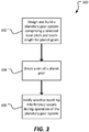
- the method 300 may begin at block 302 by designing and building a planetary gear system 100 comprising a selected base pitch and tooth length for planet gears 106 and an associated ring gear 104.
- the base pitch may comprise an already utilized or known base pitch.
- the designing and building of the planetary gear system 100 can be accomplished either by physically constructing a tangible physical system or by computer simulation (such as through the use of CATiA software produced by Dassault Systèmes or ANSYS FEM software produced by ANSYS, Inc.).
- the method 300 may continue at block 304 by breaking a rim 118 of a planet gear 106.
- breaking the rim 118 can comprise sawing through the rim 118 with a band saw and/or otherwise creating a full angular break 122 in the rim 118 that can allow unfurling of the rim 118.
- breaking the rim 118 can comprise modelling and/or simulating a full angular break 122 in the rim 118.
- the method 300 may continue at block 306 by verifying whether tooth tip interference occurs during operation of the planetary gear system 100.
- the verification of whether tooth tip interference occurs can comprise visual observation, utilization of chip detection systems, and/or any other suitable means of determining whether tooth tip interference has occurred.
- the verification of whether tooth tip interference occurs can comprise simulating operation of the planetary gear system 100.
- the simulated operation of the planetary gear system 100 can comprise animated outputs of component kinematic movements (including rim 118 unfurling) and/or other outputs indicating whether tooth tip interference has occurred in the simulation.
- R 1 R 1 +k * (R u -R 1 ), wherein k is a variable ranging from 1 percent to 100 percent with a 1 percent increment, i.e., k is 1 percent, 2 percent, 3 percent, 4 percent, 5 percent,...50 percent, 51 percent, 52 percent,..., 95 percent, 96 percent, 97 percent, 98 percent, 99 percent, or 100 percent.
- any numerical range defined by two R numbers as defined in the above is also specifically disclosed.
Landscapes
- Engineering & Computer Science (AREA)
- General Engineering & Computer Science (AREA)
- Mechanical Engineering (AREA)
- Physics & Mathematics (AREA)
- General Physics & Mathematics (AREA)
- Retarders (AREA)
Abstract
Description
- In planetary gear systems, a planet gear or a pinion gear can fail by fatigue fracture through the gear rim or by gear tooth breakage. In cases where a planet gear tooth breaks off from the planet gear, the planetary gear system can experience a catastrophic failure when the broken tooth remnants become enmeshed between planet gears and the sun gear and/or between the planet gears and the ring gear. In other cases, a failure can occur due to spalling fatigue damage or other defects to integral bearing races that induce fatigue failure through the rim of the gear. This failure mode can cause the planet pinion teeth to catastrophically lock up due to interference with the mating teeth sun or ring gear teeth. While a catastrophic failure of a planetary gear system in some applications may be an expensive inconvenience, such a failure in an aircraft propulsion system, such as, but not limited to, the propulsion system of a helicopter, can lead to fatal crashes and/or significant damage to the aircraft.
-
-
Figure 1 is an orthogonal top view of a planetary gear system according to an embodiment of this disclosure. -
Figure 2 is a flowchart of a method of avoiding gear tooth interference in a planetary gear system. -
Figure 3 is a flowchart of another method of avoiding gear tooth interference in a planetary gear system. - In the specification, reference may be made to the spatial relationships between various components and to the spatial orientation of various aspects of components as the devices are depicted in the attached drawings. However, as will be recognized by those skilled in the art after a complete reading of the present disclosure, the devices, members, apparatuses, etc. described herein may be positioned in any desired orientation. Thus, the use of terms such as "above," "below," "upper," "lower," or other like terms to describe a spatial relationship between various components or to describe the spatial orientation of aspects of such components should be understood to describe a relative relationship between the components or a spatial orientation of aspects of such components, respectively, as the device described herein may be oriented in any desired direction.
- Referring now to
Figure 1 , aplanetary gear system 100 of the present disclosure is shown. Theplanetary gear system 100 comprises asun gear 102, aring gear 104, and four planet gears 106 (or pinion gears). The fourplanet gears 106 are carried by acarrier 108. More specifically, theplanet gears 106 are rotatably mounted toposts 110 of thecarrier 108 usingroller bearings 112. Although theplanetary gear system 100 can be driven in multiple ways by restricting angular rotation of any one of thesun gear 102,ring gear 104, and thecarrier 108, operation of theplanetary gear system 100 is described herein for illustration purposes as allowing angular rotation of thesun gear 102 and thecarrier 108 about acentral axis 114 of ashaft 116 to which thesun gear 102 is mounted. Most generally, with thecarrier 108 prevented from rotating about thecentral axis 114, a clockwise rotation of theshaft 116 and associatedsun gear 102 results in the counter-clockwise rotation of theplanet gears 106 and clockwise rotation of thecarrier 108. In this embodiment, each of thesun gear 102, thering gear 104, and theplanet gears 106 are formed as involute gears so that, when functioning under normal operating conditions and without failure of any of the gears, contact between two gear teeth occurs along a single line of action (or pressure line or line of contact). While conventional planetary gear system are designed with a preference toward breaking teeth off planet gears as a primary mode of failure, theplanetary gear system 100 is designed to accommodate abreak 122 in arim 118 of aplanet gear 106. Therims 118 can most generally be described as comprising the material of theplanet gears 106 that exists radially inward (toward the associated posts 110) from the root circle (comprising a root diameter) of theplanet gears 106. More generally, therims 118 comprise the material of theplanet gears 106 that carryplanet gear teeth 120. - Still referring to
Figure 1 , theplanetary gear system 100 is shown with a break 122 (or a through crack). When theplanetary gear system 100 operates as described with respect toFigure 1 , thebreak 122 rotates counter-clockwise about the associatedpost 110. When thebreak 122 has passed engagement of the teeth of thesun gear 102 and is approaching thering gear 104, the ends of thebroken rim 118 are in compression so that thebroken planet gear 106 generally behaves normally and is not significantly distorted or out of round. However, when thebreak 122 has passed engagement with the teeth of thering gear 104 and is approaching thesun gear 102, the forces applied to thebroken planet gear 106 by thesun gear 102 and thering gear 104 tend to separate the ends of thebroken rim 118. As a function of the separation, therim 118 is forced out of round so that the portion of therim 118 from thebreak 122 to the interface between thebroken planet gear 106 and thering gear 104 is distorted and may be partially elastically unfurled and/or partially straightened relative to the original circular shape of therim 118. Even though the unfurling may only be temporary due to the at least partially elastic nature of the bending, the unfurling may alter the meshing characteristics of theplanet gear 106 relative to thering gear 104. While high contact ratio planetary gear systems with relatively longer teeth may experience binding or tooth interference between thebroken planet gear 106 and thering gear 104 or thesun gear 102, theplanetary gear system 100 of the present disclosure is designed so that the unfurling is anticipated and accommodated in the size and shape of theplanet gear teeth 120 and/or thering gear teeth 124 of thering gear 104 and/or thesun gear teeth 125. - One result of accommodating the unfurling of the
broken planet gear 106 is that during the unfurling and/or while thebroken planet gear 106 is in an unfurled state, thebroken planet gear 106 bears a lesser load than under normal conditions. However, because the total load applied to the group ofplanet gears 106 is not diminished when thebroken planet gear 106 at least partially unfurls, the effective force transfer capability of thebroken planet gear 106 is realized elsewhere by theunbroken planet gears 106 as a collective increase in load commensurate to that which would normally applied to thebroken planet gear 106 prior to breakage. This load redistribution to the other planets creates a self-limiting amount of unfurling thebroken planet gear 106 can undergo. In other words, thebroken planet gear 106 may at least partially or fully behave as an idler gear that, while still meshing with other gears without destructive interference, contributes less toward transferring load between thesun gear 102 and thering gear 104. Another potential result of the unfurling of thebroken planet gear 106 is that as the number of rotations of thebroken planet gear 106 increases, therim 118 experiences cyclic and repetitive flexure, in some cases with the cyclic stress being concentrated primarily about 180 degrees angularly offset from theinitial break 122. Over time, the application of such cyclic stress may lead to fatigue cracking of the alreadybroken planet gear 106 and separation of one portion of thebroken planet gear 106 from another, yielding two separate portions. However, because such a potentially catastrophic outcome is anticipated, other systems and methods, such as chip detection systems are utilized to notify an operator of theinitial break 122 and/or automatically initiate a reduction in the forces or cycles applied to thebroken planet gear 106. The above-mentioned chip detection is a reliable method of determining theinitial break 122 because theroller bearings 112 will contact the irregular interface of thebreak 122 and generate material fragment castoffs from therim 118 and/or theroller bearings 112 themselves. - Providing
planetary gear system 100 with the above-described capability to accommodate a partial unfurling of therim 118 requires consideration of many geometric, kinematic, and thermodynamic aspects of the components of theplanetary gear system 100. Complementary involute gears need to have complementary and specific base pitches as well as diametrical pitches. If an involute profile of an involute gear varies from the appropriate involute path, a transmission error can occur which can result in noise and/or vibration. However, considering that gear teeth generally deflect under load, the involute profile is typically modified so that the implemented involute profile of a gear follows a true involute path under the anticipated deflection. A primary factor in ensuring nondestructive meshing betweenbroken planet gear 106 and thering gear 104 and thesun gear teeth 125 is to select an appropriateplanet gear tooth 120 length. In other words, selecting appropriate tooth dedendums and tooth addendums can greatly affect whether a broken and at least partiallyunfurled planet gear 106 can mesh with thering gear 104 orsun gear 102. Further, anunbroken planet gear 106 and acomplementary ring gear 104 andsun gear 102 need to comprise substantially the same base pitch to mesh well. However, with sufficient unfurling of therim 118, the kinematics of the interface between thebroken planet gear 106 and thering gear 104 andsun gear 102 can be sufficiently changed so that the base pitch is different (typically more than the base pitch of the unbroken planet gear 106) and may result in undesirable and destructive tooth tip interference. One way to accommodate the variance in base pitch of thebroken planet gear 106 is to shorten the teeth of one or both of theplanet gear 106 and thering gear 104 andsun gear 102. - Referring now to
Figure 2 , a flowchart of amethod 200 of avoiding gear tooth interference in a planetary gear system, such asplanetary gear system 100, is shown. Themethod 200 may begin atblock 202 by selecting a base pitch and tooth length forplanet gears 106 and an associatedring gear 104 andsun gear 102. In some cases, the base pitch may comprise an already utilized or known base pitch. Themethod 200 may continue atblock 204 by determining a change in effective base pitch as a function of an unfurling of abroken rim 118 or deflection of abroken rim 118 of theplanet gear 106. In some cases, a predicted maximum change in effective base pitch can be utilized to determine the change in effective base pitch. Next, themethod 200 may continue atblock 206 by determining whether the effective base pitch of thebroken planet gear 106 can mesh with thering gear 104 andsun gear 102 without tooth tip interference. If the answer atblock 206 is no, the tooth length of theplanet gear 106 is too long. Themethod 200 can continue atblock 208 to optimize the tooth length of theplanet gear 106 by repeatedly selectingshorter planet gear 106 tooth lengths and repeatingblock 206 until the answer atblock 206 is yes. If the answer atblock 206 is initially yes, themethod 200 can continue atblock 210 to optimize the tooth length of theplanet gear 106 by repeatedly selecting longer tooth lengths and repeatingblock 206 until the answer atblock 206 is no. Once the answer atblock 206 is no, a tooth length associated with a last determined yes answer toblock 206 can be selected, thereby optimizing the tooth length and providing a highest tooth contact ratio that is compatible with the predicted maximum change in effective base pitch. - Referring now to
Figure 3 , a flowchart of amethod 300 of avoiding gear tooth interference in a planetary gear system, such asplanetary gear system 100, is shown. Themethod 300 may begin atblock 302 by designing and building aplanetary gear system 100 comprising a selected base pitch and tooth length forplanet gears 106 and an associatedring gear 104. In some cases, the base pitch may comprise an already utilized or known base pitch. The designing and building of theplanetary gear system 100 can be accomplished either by physically constructing a tangible physical system or by computer simulation (such as through the use of CATiA software produced by Dassault Systèmes or ANSYS FEM software produced by ANSYS, Inc.). Additional design factors beyond the tooth length and base pitch that affect whether theplanetary gear system 100 can accommodate anunfurling rim 118 include, but are not limited to, contact ratio (based in part on tooth height), backlash (based on tooth thickness), cross-sectional stiffness of therim 118, tooth deflection under load, and typical gear meshing tolerances. Themethod 300 may continue atblock 304 by breaking arim 118 of aplanet gear 106. In cases whereblock 302 results in a physical embodiment of theplanetary gear system 100, breaking therim 118 can comprise sawing through therim 118 with a band saw and/or otherwise creating a fullangular break 122 in therim 118 that can allow unfurling of therim 118. In cases whereblock 302 is computer simulated, breaking therim 118 can comprise modelling and/or simulating a fullangular break 122 in therim 118. Next, themethod 300 may continue atblock 306 by verifying whether tooth tip interference occurs during operation of theplanetary gear system 100. In cases where a physical embodiment of theplanetary gear system 100 is produced atblock 302, the verification of whether tooth tip interference occurs can comprise visual observation, utilization of chip detection systems, and/or any other suitable means of determining whether tooth tip interference has occurred. In cases where a computer simulation is produced atblock 302, the verification of whether tooth tip interference occurs can comprise simulating operation of theplanetary gear system 100. The simulated operation of theplanetary gear system 100 can comprise animated outputs of component kinematic movements (includingrim 118 unfurling) and/or other outputs indicating whether tooth tip interference has occurred in the simulation. - At least one embodiment is disclosed and variations, combinations, and/or modifications of the embodiment(s) and/or features of the embodiment(s) made by a person having ordinary skill in the art are within the scope of the disclosure. Alternative embodiments that result from combining, integrating, and/or omitting features of the embodiment(s) are also within the scope of the disclosure. Where numerical ranges or limitations are expressly stated, such express ranges or limitations should be understood to include iterative ranges or limitations of like magnitude falling within the expressly stated ranges or limitations (e.g., from about 1 to about 10 includes, 2, 3, 4, etc.; greater than 0.10 includes 0.11, 0.12, 0.13, etc.). For example, whenever a numerical range with a lower limit, R1, and an upper limit, Ru, is disclosed, any number falling within the range is specifically disclosed. In particular, the following numbers within the range are specifically disclosed: R=R1 +k * (Ru-R1), wherein k is a variable ranging from 1 percent to 100 percent with a 1 percent increment, i.e., k is 1 percent, 2 percent, 3 percent, 4 percent, 5 percent,...50 percent, 51 percent, 52 percent,..., 95 percent, 96 percent, 97 percent, 98 percent, 99 percent, or 100 percent. Moreover, any numerical range defined by two R numbers as defined in the above is also specifically disclosed. Use of the term "optionally" with respect to any element of a claim means that the element is required, or alternatively, the element is not required, both alternatives being within the scope of the claim. Use of broader terms such as comprises, includes, and having should be understood to provide support for narrower terms such as consisting of, consisting essentially of, and comprised substantially of. Accordingly, the scope of protection is not limited by the description set out above but is defined by the claims that follow, that scope including all equivalents of the subject matter of the claims. Each and every claim is incorporated as further disclosure into the specification and the claims are embodiment(s) of the present invention.
Claims (15)
- A method of avoiding gear tooth interference in a planetary gear system, comprising:designing and building a planetary gear system comprising a selected base pitch and tooth length for planet gears;breaking a rim of one of the planet gears; andverifying whether tooth tip interference occurs during operation of the planetary gear system.
- The method of claim 1, wherein the designing and building results in a tangible physical system.
- The method of claim 2, wherein breaking the rim comprises providing a full angular break in the rim that can allow unfurling of the rim, wherein the breaking of the rim optionally comprises sawing the rim using a band saw.
- The method of any preceding claim, wherein the designing and building results in computer simulation of the planetary gear system, wherein breaking the rim optionally comprises modelling and/or simulating a full angular break in the rim that can allow unfurling of the rim.
- The method of any preceding claim, wherein the verifying comprises at least one of:i) simulating operation of the planetary gear system; ii) use of a chip detection system; and; iii) visual inspection.
- A method of avoiding gear tooth interference in a planetary gear system, comprising:selecting a base pitch and tooth length for planet gears;determining a change in effective base pitch as a function of an unfurling or deflection of a broken planet gear rim; anddetermining whether the effective base pitch of the broken planet gear can mesh with the ring gear and sun gear without tooth tip interference.
- The method of claim 6, further comprising:in response to determining that the effective base pitch of the broken planet gear cannot mesh with the ring gear and sun gear without tooth tip interference, selecting a shorter tooth length.
- The method of claim 7, further comprising:after selecting the shorter tooth length, determining whether the effective base pitch of the broken planet gear can mesh with the ring gear and sun gear without tooth tip interference.
- The method of claim 7 or 8, further comprising:in response to determining that the effective base pitch of the broken planet gear can mesh with the ring gear and sun gear without tooth tip interference, selecting a longer tooth length.
- The method of claim 9, further comprising:after selecting the longer tooth length, determining whether the effective base pitch of the broken planet gear can mesh with the ring gear and sun gear without tooth tip interference.
- A planetary gear set, comprising:a sun gear comprising sun gear teeth;a ring gear comprising ring gear teeth; anda plurality of planet gears comprising planet gear teeth;wherein a base pitch and a tooth length of the planet gears are selected to accommodate a partial unfurling of a rim of one of the planet gears without causing tooth tip interference with the ring gear or the sun gear.
- The planetary gear set of claim 11, wherein the unfurling is accomplished as a function of a full angular break in the rim.
- The planetary gear set of claim 12, wherein the full angular break is formed in the rim comprises a saw cut.
- The planetary gear set of claim 13, wherein the unfurling comprises an elastic bending of the rim.
- The planetary gear set of claim 14, wherein the sun gear, the ring gear, and the plurality of planet gears comprise involute gears.
Priority Applications (1)
| Application Number | Priority Date | Filing Date | Title |
|---|---|---|---|
| EP20185572.3A EP3779241B1 (en) | 2017-07-21 | 2017-08-18 | Method for verifying whether tooth tip interference occurs in a planetary gear system |
Applications Claiming Priority (1)
| Application Number | Priority Date | Filing Date | Title |
|---|---|---|---|
| US15/656,420 US10578208B2 (en) | 2017-07-21 | 2017-07-21 | Method of avoiding gear tooth interference in a planetary gear system |
Related Child Applications (1)
| Application Number | Title | Priority Date | Filing Date |
|---|---|---|---|
| EP20185572.3A Division EP3779241B1 (en) | 2017-07-21 | 2017-08-18 | Method for verifying whether tooth tip interference occurs in a planetary gear system |
Publications (2)
| Publication Number | Publication Date |
|---|---|
| EP3431818A1 true EP3431818A1 (en) | 2019-01-23 |
| EP3431818B1 EP3431818B1 (en) | 2020-07-15 |
Family
ID=59699505
Family Applications (2)
| Application Number | Title | Priority Date | Filing Date |
|---|---|---|---|
| EP17186843.3A Active EP3431818B1 (en) | 2017-07-21 | 2017-08-18 | Method of avoiding gear tooth interference in a planetary gear system |
| EP20185572.3A Active EP3779241B1 (en) | 2017-07-21 | 2017-08-18 | Method for verifying whether tooth tip interference occurs in a planetary gear system |
Family Applications After (1)
| Application Number | Title | Priority Date | Filing Date |
|---|---|---|---|
| EP20185572.3A Active EP3779241B1 (en) | 2017-07-21 | 2017-08-18 | Method for verifying whether tooth tip interference occurs in a planetary gear system |
Country Status (3)
| Country | Link |
|---|---|
| US (1) | US10578208B2 (en) |
| EP (2) | EP3431818B1 (en) |
| CA (1) | CA3012148C (en) |
Families Citing this family (1)
| Publication number | Priority date | Publication date | Assignee | Title |
|---|---|---|---|---|
| US12522351B1 (en) * | 2025-01-27 | 2026-01-13 | Textron Innovations Inc. | Planetary pinion gear deflection restraint device |
Citations (2)
| Publication number | Priority date | Publication date | Assignee | Title |
|---|---|---|---|---|
| US20100256932A1 (en) * | 2009-04-02 | 2010-10-07 | Honeywell International Inc. | System and method for gearbox health monitoring |
| US8777800B2 (en) * | 2010-03-19 | 2014-07-15 | Airbus Helicopters | Mechanical assembly provided with means for monitoring for a structural anomaly, a gearbox provided with such a mechanical assembly, and a method of monitoring for a structural anomaly |
Family Cites Families (2)
| Publication number | Priority date | Publication date | Assignee | Title |
|---|---|---|---|---|
| US8562481B2 (en) * | 2009-09-18 | 2013-10-22 | Kiss Engineering, Llc | Gearing with cylindrical tooth forms |
| US10969001B2 (en) * | 2017-07-21 | 2021-04-06 | Textron Innovations Inc. | Planet gear having failure mode optimized for continued planetary gear system operation |
-
2017
- 2017-07-21 US US15/656,420 patent/US10578208B2/en active Active
- 2017-08-18 EP EP17186843.3A patent/EP3431818B1/en active Active
- 2017-08-18 EP EP20185572.3A patent/EP3779241B1/en active Active
-
2018
- 2018-07-20 CA CA3012148A patent/CA3012148C/en active Active
Patent Citations (2)
| Publication number | Priority date | Publication date | Assignee | Title |
|---|---|---|---|---|
| US20100256932A1 (en) * | 2009-04-02 | 2010-10-07 | Honeywell International Inc. | System and method for gearbox health monitoring |
| US8777800B2 (en) * | 2010-03-19 | 2014-07-15 | Airbus Helicopters | Mechanical assembly provided with means for monitoring for a structural anomaly, a gearbox provided with such a mechanical assembly, and a method of monitoring for a structural anomaly |
Also Published As
| Publication number | Publication date |
|---|---|
| EP3779241B1 (en) | 2023-11-08 |
| US10578208B2 (en) | 2020-03-03 |
| CA3012148C (en) | 2020-07-07 |
| US20190024779A1 (en) | 2019-01-24 |
| CA3012148A1 (en) | 2019-01-21 |
| EP3431818B1 (en) | 2020-07-15 |
| EP3779241A1 (en) | 2021-02-17 |
Similar Documents
| Publication | Publication Date | Title |
|---|---|---|
| Karataş et al. | Effect of movement kinematics on the cyclic fatigue resistance of nickel–titanium instruments | |
| US9611746B2 (en) | Blade wedge attachment | |
| US9915334B2 (en) | Flex spline for use with a compound harmonic generator | |
| JP5490752B2 (en) | Swing intermeshing type speed reducer | |
| CA3012148C (en) | Method of avoiding gear tooth interference in a planetary gear system | |
| CN105308266B (en) | rotating body with blades | |
| US10969001B2 (en) | Planet gear having failure mode optimized for continued planetary gear system operation | |
| CN109826758A (en) | Method and device for determining abnormal pitch variation of fan and fan control system | |
| EP2913559A1 (en) | A gearing arrangement | |
| US20150292577A1 (en) | Damped anti-rotational systems | |
| CN103267106B (en) | There are the helical gear of Fibonacci helix profile of tooth | |
| Xia et al. | Effects of contact interfaces on rotor dynamic characteristics of heavy-duty gas turbine generator set | |
| JP2012529604A (en) | Gear pair | |
| Kissling et al. | A procedure to determine the optimum flank line modifications for planetary gear configurations | |
| Wang et al. | Methodology Of Open Bladed Impeller Resonance Indentification. | |
| Plekhanov | Deformability of units of a planetary gear and its effect on load distribution in gear meshes | |
| US11067163B2 (en) | Epicycic geartrain, a gearbox, and aircraft, and a method | |
| EP2299110A1 (en) | Bearing mechanism | |
| CN110337532B (en) | Aircraft engine comprising a bearing between two concentric shafts | |
| CN107178582A (en) | A kind of planetary transmission with variable cross-section flexible pin shaft | |
| Lias et al. | Investigation of axial misalignment effects to the gear tooth strength properties using FEM model | |
| CN205013633U (en) | Improvement structure suitable for loader torque converter | |
| JP6602582B2 (en) | Nut detent mechanism | |
| Park et al. | Characteristics analysis of wind turbine gearbox considering fatigue loads caused by wind fluctuation | |
| JP2015129571A (en) | Double-helical gear |
Legal Events
| Date | Code | Title | Description |
|---|---|---|---|
| STAA | Information on the status of an ep patent application or granted ep patent |
Free format text: STATUS: EXAMINATION IS IN PROGRESS |
|
| PUAI | Public reference made under article 153(3) epc to a published international application that has entered the european phase |
Free format text: ORIGINAL CODE: 0009012 |
|
| 17P | Request for examination filed |
Effective date: 20170818 |
|
| AK | Designated contracting states |
Kind code of ref document: A1 Designated state(s): AL AT BE BG CH CY CZ DE DK EE ES FI FR GB GR HR HU IE IS IT LI LT LU LV MC MK MT NL NO PL PT RO RS SE SI SK SM TR |
|
| AX | Request for extension of the european patent |
Extension state: BA ME |
|
| GRAP | Despatch of communication of intention to grant a patent |
Free format text: ORIGINAL CODE: EPIDOSNIGR1 |
|
| STAA | Information on the status of an ep patent application or granted ep patent |
Free format text: STATUS: GRANT OF PATENT IS INTENDED |
|
| RIC1 | Information provided on ipc code assigned before grant |
Ipc: F16H 55/08 20060101AFI20200107BHEP Ipc: G01M 13/02 20190101ALI20200107BHEP Ipc: F16H 57/00 20120101ALN20200107BHEP Ipc: F16H 57/08 20060101ALI20200107BHEP |
|
| INTG | Intention to grant announced |
Effective date: 20200207 |
|
| GRAS | Grant fee paid |
Free format text: ORIGINAL CODE: EPIDOSNIGR3 |
|
| GRAA | (expected) grant |
Free format text: ORIGINAL CODE: 0009210 |
|
| STAA | Information on the status of an ep patent application or granted ep patent |
Free format text: STATUS: THE PATENT HAS BEEN GRANTED |
|
| AK | Designated contracting states |
Kind code of ref document: B1 Designated state(s): AL AT BE BG CH CY CZ DE DK EE ES FI FR GB GR HR HU IE IS IT LI LT LU LV MC MK MT NL NO PL PT RO RS SE SI SK SM TR |
|
| REG | Reference to a national code |
Ref country code: CH Ref legal event code: EP Ref country code: GB Ref legal event code: FG4D |
|
| REG | Reference to a national code |
Ref country code: DE Ref legal event code: R096 Ref document number: 602017019691 Country of ref document: DE |
|
| REG | Reference to a national code |
Ref country code: IE Ref legal event code: FG4D |
|
| REG | Reference to a national code |
Ref country code: AT Ref legal event code: REF Ref document number: 1291390 Country of ref document: AT Kind code of ref document: T Effective date: 20200815 |
|
| REG | Reference to a national code |
Ref country code: LT Ref legal event code: MG4D |
|
| REG | Reference to a national code |
Ref country code: AT Ref legal event code: MK05 Ref document number: 1291390 Country of ref document: AT Kind code of ref document: T Effective date: 20200715 |
|
| REG | Reference to a national code |
Ref country code: NL Ref legal event code: MP Effective date: 20200715 |
|
| PG25 | Lapsed in a contracting state [announced via postgrant information from national office to epo] |
Ref country code: PT Free format text: LAPSE BECAUSE OF FAILURE TO SUBMIT A TRANSLATION OF THE DESCRIPTION OR TO PAY THE FEE WITHIN THE PRESCRIBED TIME-LIMIT Effective date: 20201116 Ref country code: FI Free format text: LAPSE BECAUSE OF FAILURE TO SUBMIT A TRANSLATION OF THE DESCRIPTION OR TO PAY THE FEE WITHIN THE PRESCRIBED TIME-LIMIT Effective date: 20200715 Ref country code: LT Free format text: LAPSE BECAUSE OF FAILURE TO SUBMIT A TRANSLATION OF THE DESCRIPTION OR TO PAY THE FEE WITHIN THE PRESCRIBED TIME-LIMIT Effective date: 20200715 Ref country code: SE Free format text: LAPSE BECAUSE OF FAILURE TO SUBMIT A TRANSLATION OF THE DESCRIPTION OR TO PAY THE FEE WITHIN THE PRESCRIBED TIME-LIMIT Effective date: 20200715 Ref country code: HR Free format text: LAPSE BECAUSE OF FAILURE TO SUBMIT A TRANSLATION OF THE DESCRIPTION OR TO PAY THE FEE WITHIN THE PRESCRIBED TIME-LIMIT Effective date: 20200715 Ref country code: ES Free format text: LAPSE BECAUSE OF FAILURE TO SUBMIT A TRANSLATION OF THE DESCRIPTION OR TO PAY THE FEE WITHIN THE PRESCRIBED TIME-LIMIT Effective date: 20200715 Ref country code: BG Free format text: LAPSE BECAUSE OF FAILURE TO SUBMIT A TRANSLATION OF THE DESCRIPTION OR TO PAY THE FEE WITHIN THE PRESCRIBED TIME-LIMIT Effective date: 20201015 Ref country code: NO Free format text: LAPSE BECAUSE OF FAILURE TO SUBMIT A TRANSLATION OF THE DESCRIPTION OR TO PAY THE FEE WITHIN THE PRESCRIBED TIME-LIMIT Effective date: 20201015 Ref country code: GR Free format text: LAPSE BECAUSE OF FAILURE TO SUBMIT A TRANSLATION OF THE DESCRIPTION OR TO PAY THE FEE WITHIN THE PRESCRIBED TIME-LIMIT Effective date: 20201016 Ref country code: AT Free format text: LAPSE BECAUSE OF FAILURE TO SUBMIT A TRANSLATION OF THE DESCRIPTION OR TO PAY THE FEE WITHIN THE PRESCRIBED TIME-LIMIT Effective date: 20200715 |
|
| PG25 | Lapsed in a contracting state [announced via postgrant information from national office to epo] |
Ref country code: RS Free format text: LAPSE BECAUSE OF FAILURE TO SUBMIT A TRANSLATION OF THE DESCRIPTION OR TO PAY THE FEE WITHIN THE PRESCRIBED TIME-LIMIT Effective date: 20200715 Ref country code: PL Free format text: LAPSE BECAUSE OF FAILURE TO SUBMIT A TRANSLATION OF THE DESCRIPTION OR TO PAY THE FEE WITHIN THE PRESCRIBED TIME-LIMIT Effective date: 20200715 Ref country code: LV Free format text: LAPSE BECAUSE OF FAILURE TO SUBMIT A TRANSLATION OF THE DESCRIPTION OR TO PAY THE FEE WITHIN THE PRESCRIBED TIME-LIMIT Effective date: 20200715 Ref country code: IS Free format text: LAPSE BECAUSE OF FAILURE TO SUBMIT A TRANSLATION OF THE DESCRIPTION OR TO PAY THE FEE WITHIN THE PRESCRIBED TIME-LIMIT Effective date: 20201115 |
|
| PG25 | Lapsed in a contracting state [announced via postgrant information from national office to epo] |
Ref country code: NL Free format text: LAPSE BECAUSE OF FAILURE TO SUBMIT A TRANSLATION OF THE DESCRIPTION OR TO PAY THE FEE WITHIN THE PRESCRIBED TIME-LIMIT Effective date: 20200715 |
|
| REG | Reference to a national code |
Ref country code: CH Ref legal event code: PL |
|
| REG | Reference to a national code |
Ref country code: DE Ref legal event code: R097 Ref document number: 602017019691 Country of ref document: DE |
|
| PG25 | Lapsed in a contracting state [announced via postgrant information from national office to epo] |
Ref country code: LU Free format text: LAPSE BECAUSE OF NON-PAYMENT OF DUE FEES Effective date: 20200818 Ref country code: LI Free format text: LAPSE BECAUSE OF NON-PAYMENT OF DUE FEES Effective date: 20200831 Ref country code: DK Free format text: LAPSE BECAUSE OF FAILURE TO SUBMIT A TRANSLATION OF THE DESCRIPTION OR TO PAY THE FEE WITHIN THE PRESCRIBED TIME-LIMIT Effective date: 20200715 Ref country code: CH Free format text: LAPSE BECAUSE OF NON-PAYMENT OF DUE FEES Effective date: 20200831 Ref country code: CZ Free format text: LAPSE BECAUSE OF FAILURE TO SUBMIT A TRANSLATION OF THE DESCRIPTION OR TO PAY THE FEE WITHIN THE PRESCRIBED TIME-LIMIT Effective date: 20200715 Ref country code: RO Free format text: LAPSE BECAUSE OF FAILURE TO SUBMIT A TRANSLATION OF THE DESCRIPTION OR TO PAY THE FEE WITHIN THE PRESCRIBED TIME-LIMIT Effective date: 20200715 Ref country code: EE Free format text: LAPSE BECAUSE OF FAILURE TO SUBMIT A TRANSLATION OF THE DESCRIPTION OR TO PAY THE FEE WITHIN THE PRESCRIBED TIME-LIMIT Effective date: 20200715 Ref country code: SM Free format text: LAPSE BECAUSE OF FAILURE TO SUBMIT A TRANSLATION OF THE DESCRIPTION OR TO PAY THE FEE WITHIN THE PRESCRIBED TIME-LIMIT Effective date: 20200715 |
|
| PLBE | No opposition filed within time limit |
Free format text: ORIGINAL CODE: 0009261 |
|
| STAA | Information on the status of an ep patent application or granted ep patent |
Free format text: STATUS: NO OPPOSITION FILED WITHIN TIME LIMIT |
|
| REG | Reference to a national code |
Ref country code: BE Ref legal event code: MM Effective date: 20200831 |
|
| PG25 | Lapsed in a contracting state [announced via postgrant information from national office to epo] |
Ref country code: AL Free format text: LAPSE BECAUSE OF FAILURE TO SUBMIT A TRANSLATION OF THE DESCRIPTION OR TO PAY THE FEE WITHIN THE PRESCRIBED TIME-LIMIT Effective date: 20200715 |
|
| 26N | No opposition filed |
Effective date: 20210416 |
|
| PG25 | Lapsed in a contracting state [announced via postgrant information from national office to epo] |
Ref country code: SK Free format text: LAPSE BECAUSE OF FAILURE TO SUBMIT A TRANSLATION OF THE DESCRIPTION OR TO PAY THE FEE WITHIN THE PRESCRIBED TIME-LIMIT Effective date: 20200715 |
|
| PG25 | Lapsed in a contracting state [announced via postgrant information from national office to epo] |
Ref country code: SI Free format text: LAPSE BECAUSE OF FAILURE TO SUBMIT A TRANSLATION OF THE DESCRIPTION OR TO PAY THE FEE WITHIN THE PRESCRIBED TIME-LIMIT Effective date: 20200715 Ref country code: IE Free format text: LAPSE BECAUSE OF NON-PAYMENT OF DUE FEES Effective date: 20200818 Ref country code: BE Free format text: LAPSE BECAUSE OF NON-PAYMENT OF DUE FEES Effective date: 20200831 |
|
| PG25 | Lapsed in a contracting state [announced via postgrant information from national office to epo] |
Ref country code: TR Free format text: LAPSE BECAUSE OF FAILURE TO SUBMIT A TRANSLATION OF THE DESCRIPTION OR TO PAY THE FEE WITHIN THE PRESCRIBED TIME-LIMIT Effective date: 20200715 Ref country code: MT Free format text: LAPSE BECAUSE OF FAILURE TO SUBMIT A TRANSLATION OF THE DESCRIPTION OR TO PAY THE FEE WITHIN THE PRESCRIBED TIME-LIMIT Effective date: 20200715 Ref country code: CY Free format text: LAPSE BECAUSE OF FAILURE TO SUBMIT A TRANSLATION OF THE DESCRIPTION OR TO PAY THE FEE WITHIN THE PRESCRIBED TIME-LIMIT Effective date: 20200715 |
|
| PG25 | Lapsed in a contracting state [announced via postgrant information from national office to epo] |
Ref country code: MK Free format text: LAPSE BECAUSE OF FAILURE TO SUBMIT A TRANSLATION OF THE DESCRIPTION OR TO PAY THE FEE WITHIN THE PRESCRIBED TIME-LIMIT Effective date: 20200715 Ref country code: MC Free format text: LAPSE BECAUSE OF FAILURE TO SUBMIT A TRANSLATION OF THE DESCRIPTION OR TO PAY THE FEE WITHIN THE PRESCRIBED TIME-LIMIT Effective date: 20200715 |
|
| P01 | Opt-out of the competence of the unified patent court (upc) registered |
Effective date: 20230602 |
|
| PGFP | Annual fee paid to national office [announced via postgrant information from national office to epo] |
Ref country code: DE Payment date: 20250827 Year of fee payment: 9 |
|
| PGFP | Annual fee paid to national office [announced via postgrant information from national office to epo] |
Ref country code: IT Payment date: 20250820 Year of fee payment: 9 |
|
| PGFP | Annual fee paid to national office [announced via postgrant information from national office to epo] |
Ref country code: GB Payment date: 20250827 Year of fee payment: 9 |
|
| PGFP | Annual fee paid to national office [announced via postgrant information from national office to epo] |
Ref country code: FR Payment date: 20250825 Year of fee payment: 9 |