EP3431730B1 - Fluid spray injectors - Google Patents
Fluid spray injectors Download PDFInfo
- Publication number
- EP3431730B1 EP3431730B1 EP18181620.8A EP18181620A EP3431730B1 EP 3431730 B1 EP3431730 B1 EP 3431730B1 EP 18181620 A EP18181620 A EP 18181620A EP 3431730 B1 EP3431730 B1 EP 3431730B1
- Authority
- EP
- European Patent Office
- Prior art keywords
- pintle
- sealing surface
- feed
- nozzle tip
- spray outlet
- Prior art date
- Legal status (The legal status is an assumption and is not a legal conclusion. Google has not performed a legal analysis and makes no representation as to the accuracy of the status listed.)
- Active
Links
Images


Classifications
-
- B—PERFORMING OPERATIONS; TRANSPORTING
- B05—SPRAYING OR ATOMISING IN GENERAL; APPLYING FLUENT MATERIALS TO SURFACES, IN GENERAL
- B05B—SPRAYING APPARATUS; ATOMISING APPARATUS; NOZZLES
- B05B1/00—Nozzles, spray heads or other outlets, with or without auxiliary devices such as valves, heating means
- B05B1/34—Nozzles, spray heads or other outlets, with or without auxiliary devices such as valves, heating means designed to influence the nature of flow of the liquid or other fluent material, e.g. to produce swirl
- B05B1/3405—Nozzles, spray heads or other outlets, with or without auxiliary devices such as valves, heating means designed to influence the nature of flow of the liquid or other fluent material, e.g. to produce swirl to produce swirl
- B05B1/341—Nozzles, spray heads or other outlets, with or without auxiliary devices such as valves, heating means designed to influence the nature of flow of the liquid or other fluent material, e.g. to produce swirl to produce swirl before discharging the liquid or other fluent material, e.g. in a swirl chamber upstream the spray outlet
- B05B1/3415—Nozzles, spray heads or other outlets, with or without auxiliary devices such as valves, heating means designed to influence the nature of flow of the liquid or other fluent material, e.g. to produce swirl to produce swirl before discharging the liquid or other fluent material, e.g. in a swirl chamber upstream the spray outlet with swirl imparting inserts upstream of the swirl chamber
-
- F—MECHANICAL ENGINEERING; LIGHTING; HEATING; WEAPONS; BLASTING
- F01—MACHINES OR ENGINES IN GENERAL; ENGINE PLANTS IN GENERAL; STEAM ENGINES
- F01N—GAS-FLOW SILENCERS OR EXHAUST APPARATUS FOR MACHINES OR ENGINES IN GENERAL; GAS-FLOW SILENCERS OR EXHAUST APPARATUS FOR INTERNAL-COMBUSTION ENGINES
- F01N3/00—Exhaust or silencing apparatus having means for purifying, rendering innocuous, or otherwise treating exhaust
- F01N3/08—Exhaust or silencing apparatus having means for purifying, rendering innocuous, or otherwise treating exhaust for rendering innocuous
- F01N3/10—Exhaust or silencing apparatus having means for purifying, rendering innocuous, or otherwise treating exhaust for rendering innocuous by thermal or catalytic conversion of noxious components of exhaust
- F01N3/18—Exhaust or silencing apparatus having means for purifying, rendering innocuous, or otherwise treating exhaust for rendering innocuous by thermal or catalytic conversion of noxious components of exhaust characterised by methods of operation; Control
- F01N3/20—Exhaust or silencing apparatus having means for purifying, rendering innocuous, or otherwise treating exhaust for rendering innocuous by thermal or catalytic conversion of noxious components of exhaust characterised by methods of operation; Control specially adapted for catalytic conversion
- F01N3/206—Adding periodically or continuously substances to exhaust gases for promoting purification, e.g. catalytic material in liquid form, NOx reducing agents
- F01N3/2066—Selective catalytic reduction [SCR]
-
- B—PERFORMING OPERATIONS; TRANSPORTING
- B05—SPRAYING OR ATOMISING IN GENERAL; APPLYING FLUENT MATERIALS TO SURFACES, IN GENERAL
- B05B—SPRAYING APPARATUS; ATOMISING APPARATUS; NOZZLES
- B05B1/00—Nozzles, spray heads or other outlets, with or without auxiliary devices such as valves, heating means
- B05B1/02—Nozzles, spray heads or other outlets, with or without auxiliary devices such as valves, heating means designed to produce a jet, spray, or other discharge of particular shape or nature, e.g. in single drops, or having an outlet of particular shape
- B05B1/06—Nozzles, spray heads or other outlets, with or without auxiliary devices such as valves, heating means designed to produce a jet, spray, or other discharge of particular shape or nature, e.g. in single drops, or having an outlet of particular shape in annular, tubular or hollow conical form
-
- B—PERFORMING OPERATIONS; TRANSPORTING
- B05—SPRAYING OR ATOMISING IN GENERAL; APPLYING FLUENT MATERIALS TO SURFACES, IN GENERAL
- B05B—SPRAYING APPARATUS; ATOMISING APPARATUS; NOZZLES
- B05B1/00—Nozzles, spray heads or other outlets, with or without auxiliary devices such as valves, heating means
- B05B1/34—Nozzles, spray heads or other outlets, with or without auxiliary devices such as valves, heating means designed to influence the nature of flow of the liquid or other fluent material, e.g. to produce swirl
- B05B1/3405—Nozzles, spray heads or other outlets, with or without auxiliary devices such as valves, heating means designed to influence the nature of flow of the liquid or other fluent material, e.g. to produce swirl to produce swirl
- B05B1/341—Nozzles, spray heads or other outlets, with or without auxiliary devices such as valves, heating means designed to influence the nature of flow of the liquid or other fluent material, e.g. to produce swirl to produce swirl before discharging the liquid or other fluent material, e.g. in a swirl chamber upstream the spray outlet
- B05B1/3494—Nozzles, spray heads or other outlets, with or without auxiliary devices such as valves, heating means designed to influence the nature of flow of the liquid or other fluent material, e.g. to produce swirl to produce swirl before discharging the liquid or other fluent material, e.g. in a swirl chamber upstream the spray outlet the discharge outlet being not on the axis of the swirl chamber
-
- B—PERFORMING OPERATIONS; TRANSPORTING
- B05—SPRAYING OR ATOMISING IN GENERAL; APPLYING FLUENT MATERIALS TO SURFACES, IN GENERAL
- B05B—SPRAYING APPARATUS; ATOMISING APPARATUS; NOZZLES
- B05B15/00—Details of spraying plant or spraying apparatus not otherwise provided for; Accessories
- B05B15/20—Arrangements for agitating the material to be sprayed, e.g. for stirring, mixing or homogenising
-
- F—MECHANICAL ENGINEERING; LIGHTING; HEATING; WEAPONS; BLASTING
- F02—COMBUSTION ENGINES; HOT-GAS OR COMBUSTION-PRODUCT ENGINE PLANTS
- F02M—SUPPLYING COMBUSTION ENGINES IN GENERAL WITH COMBUSTIBLE MIXTURES OR CONSTITUENTS THEREOF
- F02M61/00—Fuel-injectors not provided for in groups F02M39/00 - F02M57/00 or F02M67/00
- F02M61/16—Details not provided for in, or of interest apart from, the apparatus of groups F02M61/02 - F02M61/14
- F02M61/162—Means to impart a whirling motion to fuel upstream or near discharging orifices
-
- F—MECHANICAL ENGINEERING; LIGHTING; HEATING; WEAPONS; BLASTING
- F02—COMBUSTION ENGINES; HOT-GAS OR COMBUSTION-PRODUCT ENGINE PLANTS
- F02M—SUPPLYING COMBUSTION ENGINES IN GENERAL WITH COMBUSTIBLE MIXTURES OR CONSTITUENTS THEREOF
- F02M61/00—Fuel-injectors not provided for in groups F02M39/00 - F02M57/00 or F02M67/00
- F02M61/16—Details not provided for in, or of interest apart from, the apparatus of groups F02M61/02 - F02M61/14
- F02M61/18—Injection nozzles, e.g. having valve seats; Details of valve member seated ends, not otherwise provided for
- F02M61/1853—Orifice plates
-
- F—MECHANICAL ENGINEERING; LIGHTING; HEATING; WEAPONS; BLASTING
- F01—MACHINES OR ENGINES IN GENERAL; ENGINE PLANTS IN GENERAL; STEAM ENGINES
- F01N—GAS-FLOW SILENCERS OR EXHAUST APPARATUS FOR MACHINES OR ENGINES IN GENERAL; GAS-FLOW SILENCERS OR EXHAUST APPARATUS FOR INTERNAL-COMBUSTION ENGINES
- F01N2610/00—Adding substances to exhaust gases
- F01N2610/14—Arrangements for the supply of substances, e.g. conduits
- F01N2610/1453—Sprayers or atomisers; Arrangement thereof in the exhaust apparatus
-
- Y—GENERAL TAGGING OF NEW TECHNOLOGICAL DEVELOPMENTS; GENERAL TAGGING OF CROSS-SECTIONAL TECHNOLOGIES SPANNING OVER SEVERAL SECTIONS OF THE IPC; TECHNICAL SUBJECTS COVERED BY FORMER USPC CROSS-REFERENCE ART COLLECTIONS [XRACs] AND DIGESTS
- Y02—TECHNOLOGIES OR APPLICATIONS FOR MITIGATION OR ADAPTATION AGAINST CLIMATE CHANGE
- Y02T—CLIMATE CHANGE MITIGATION TECHNOLOGIES RELATED TO TRANSPORTATION
- Y02T10/00—Road transport of goods or passengers
- Y02T10/10—Internal combustion engine [ICE] based vehicles
- Y02T10/12—Improving ICE efficiencies
Definitions
- the present disclosure relates to fluid spray injectors, e.g., for selective catalyst reduction systems that inject urea/diesel exhaust fluid for use with diesel or other suitable engines.
- SCR selective catalyst reduction
- DEF diesel exhaust fluid
- urea urea
- the injectors that are used for this injection are run on a duty-cycle to control the amount of DEF in the exhaust and are operated very frequently with short cycles.
- typical pressure-swirl atomizers require a refractory period of time before the full spray cone develops, resulting in good atomization. During this refractory period the liquid effluent is temporarily very poorly atomized.
- US 6,024,301 A discloses an atomizer spray plate for discharging fuel oil.
- US 2011/0126529 A1 discloses an air-assisted fluid injector.
- a fluid spray nozzle tip as claimed in claim 1 is provided.
- the spray outlet can have a constant cross sectional area over a full longitudinal dimension of the spray outlet.
- the spray outlet can be cylindrical.
- the spray outlet can be defined through pintle sealing surface body and partly into the feed hole body.
- the feed holes are defined at a non-normal angle relative to a centerline axis (forward or backward in a longitudinal direction of the centerline) of the nozzle tip where the at least one feed hole intersects with the spray outlet.
- the feed holes can be straight.
- the feed holes can be offset from centerline of the spray outlet to cause swirling in spray outlet.
- Each feed hole can intersect at least one other feed hole in addition to intersecting with the spray outlet.
- Each feed hole can define a feed hole axis and the spray outlet defines a spray outlet axis, wherein the feed hole axis is skewed relative to the spray outlet axis.
- the pintle sealing surface body can define a flange having a larger dimension from the centerline than the feed hole body.
- the spray outlet can effuse from the pintle sealing surface body.
- the feed holes can be recessed inwardly from the sealing surface such that the sealing surface extends at least partially over the feed holes.
- the feed holes can have a non-linear shape.
- the non-linear shape can be a tentacle shaped.
- the feed hole body can be integral with the pintle sealing surface body.
- the feed hole body can be shaped to be surrounded by a pintle to allow the pintle to seal against the pintle sealing surface to prevent flow to the feed holes.
- the sealing surface body can include a cavity configured to receive a pintle to allow the pintle to interact with the pintle sealing surface to prevent flow to the feed holes.
- a fluid spray nozzle tip can include a feed hole body that defines a plurality of feed holes and a pintle sealing surface body extending from the feed hole body and configured to allow a pintle to seal against a sealing surface thereof. At least one of the feed hole body and the pintle sealing surface body define a spray outlet in direct fluid communication with the plurality of feed holes without an upstream spin chamber.
- the spray outlet can have a constant flow area.
- the spray outlet can be cylindrical. Any other suitable shape for the spray outlet is contemplated herein.
- the spray outlet can be defined through pintle sealing surface body and partly into the feed hole body.
- the feed holes can be defined at a non-normal angle relative to centerline axis of the nozzle tip to meet the spray outlet. In certain embodiments, the feed holes can be defined at normal angle relative to centerline axis to meet the spray outlet.
- the feed holes can be straight. Any other suitable shape (e.g., a non-linear flow channel) is contemplated herein.
- the feed holes can be offset from centerline to cause swirling in spray outlet.
- the pintle sealing surface body can define a flange having a larger dimension from the centerline than the feed hole body.
- the spray outlet can spray from the pintle sealing surface body.
- the feed holes can be recessed from sealing surface such that sealing surface extends over the feed holes.
- the feed holes have tentacle shape, however, any suitably shaped flow channels are contemplated herein.
- the feed hole body can be integral with the pintle sealing surface body. It is contemplated that the feed hole body and the pintle sealing surface body can be separate pieces joined together in any suitable manner.
- the feed hole body can be shaped to be surrounded by a pintle to allow the pintle to interact with the pintle sealing surface to prevent flow to the feed holes.
- the sealing surface body can include a cavity configured to receive a pintle to allow the pintle to interact with the pintle sealing surface to prevent flow to the feed holes.
- a diesel exhaust fluid spray nozzle for a selective catalyst reduction system as claimed in claim 15 is provided.
- the nozzle tip can be integral with the housing in certain embodiments.
- FIG. 1A an illustrative view of an embodiment of a nozzle tip in accordance with the disclosure is shown in Fig. 1A and is designated generally by reference character 100.
- FIG. 1B-5 Other embodiments and/or aspects of this disclosure are shown in Figs. 1B-5 .
- the systems and methods described herein can be used to reduce time to develop atomized spray and to simplify nozzle assemblies.
- a fluid spray nozzle tip 100 includes a feed hole body 101 that defines one or more of feed holes 103 and a pintle sealing surface body 105 extending from the feed hole body 101 and configured to allow a pintle (e.g., as shown in Figs. 4 and/or 5) to seal against a sealing surface 107 thereof.
- At least one of the feed hole body 101 and the pintle sealing surface body 105 define a spray outlet 109 in direct fluid communication with the plurality of feed holes 103 without an upstream spin chamber (e.g., a spin chamber between the feed holes 103 and the spray outlet 109 that is normally included in traditional systems).
- a spin chamber is traditionally placed before the outlet to induce swirl in the flow before it enters the outlet and has a different diameter than the outlet (e.g., a larger diameter) and feeds into the outlet.
- the spray outlet 109 can be centrally located (e.g., coaxial with the centerline of the tip 100) or in any other suitable position.
- the spray outlet 109 can include any suitable opening edge 111 (e.g., sharp to cause narrower spray angle, angled (beveled) edge for wider spray angle).
- the spray outlet 109 can have a constant flow area.
- the spray outlet 109 can be cylindrical. Any other suitable shape and/or dimensions (e.g., 1 to 1 diameter to length) for the spray outlet 109 is contemplated herein.
- the spray outlet 109 can be defined through pintle sealing surface body 105 and partly into the feed hole body 101.
- the feed holes 103 are defined at a non-normal angle relative to centerline axis of the nozzle tip 100 to meet the spray outlet 109.
- the feed holes 203 of a nozzle 200 can be defined at normal angle relative to centerline axis to meet the spray outlet 109.
- the feed holes 209 may need to be perpendicular to the centerline axis.
- the feed holes 103, 203 can be straight. Any other suitable shape (e.g., a non-linear flow channel) is contemplated herein.
- the feed holes 103, 203 can be offset from centerline to cause swirling in spray outlet 109.
- the pintle sealing surface body 105 can define a flange having a larger dimension from the centerline than the feed hole body 101.
- the spray outlet 109 can spray from the pintle sealing surface body 105 as shown in Figs. 1A and 2A , or from any other suitable location.
- a nozzle 300 can include feed holes 303 that are recessed from sealing surface 307 such that sealing surface 307 extends over the feed holes 303. As shown, the sealing surface 307 can be angled instead of flat. Any suitable shape of the sealing surface 107, 307 is contemplated herein.
- the feed holes 303 have a non-linear shape (e.g., tentacle shape with curves in one or more dimensions), however, any suitably shaped flow channels are contemplated herein.
- the feed holes 303 can meet the outlet 109 offset from the centerline to cause swirling in the outlet 109 and/or can be meet at a normal angle or at any suitable tilt angle.
- the feed hole body 101, 301 can be integral with the pintle sealing surface body 105, 305 (e.g., additively manufactured, casted). It is contemplated that the feed hole body 101, 301 and the pintle sealing surface body 105, 305 can be separate pieces joined together in any suitable manner (e.g., via welding, via adhesion).
- the feed hole body 101 can be shaped to be surrounded by a pintle 413 to allow the pintle 413 to interact with the pintle sealing surface 107 to prevent flow to the feed holes 103, 203.
- the sealing surface body 105 can include a cavity 315 configured to receive a pintle 513 to allow the pintle 513 to interact with the pintle sealing surface 307 to prevent flow to the feed holes 303.
- a fluid spray nozzle 400 includes a housing 417 defining a flow cavity 419. Any suitable embodiment of a nozzle tip (e.g., tip 100, 200) as described above can be disposed at an end of the housing 417.
- a pintle 413 is disposed within the flow cavity 419 and is configured to axially actuate therein between an open position where the feed holes 103 are in fluid communication with the flow cavity 419 and a closed position (e.g., as shown in Fig. 4 ) where the pintle 413 interacts with the pintle sealing surface 107 to seal the feed holes 103 from the flow cavity 419.
- the nozzle tip 103 can be integral with the housing 417.
- Fig. 5 shows the nozzle tip 300 of Figs. 3A and 3B where the sealing surface body 305 defines a cavity 315 that can receive a pintle 513.
- Embodiments include a single piece structure that has a single orifice that causes swirling and spraying. Certain embodiments can be additively manufactured which can allow for any suitable structures and flow channels.
- Certain embodiments provide a means to very rapidly form a fully-developed conical spray. This can be particularly advantageous in applications where the injector (spray) is duty-cycled on and off, frequently (e.g., in SCR NOx reduction systems).
- Typical pressure-swirl atomizers have offset holes/slots which feed an upstream spin-chamber to establish a swirling flow-field, which then passes through a smaller diameter orifice and forms a finely atomized conical spray. Filling this spin-chamber and establishing the swirling flow-field takes time, and during this time the spray may or may not be conical and is typically very poorly atomized.
- Embodiments eliminate the spin-chamber and feed offset holes/slots directly into the orifice. This permits very rapid spray cone development with good atomization.
- Embodiments can be used as swirler for any suitable system and is not limited to use in SCR systems, or even for rapid spray development.
Landscapes
- Engineering & Computer Science (AREA)
- Chemical & Material Sciences (AREA)
- Combustion & Propulsion (AREA)
- Mechanical Engineering (AREA)
- General Engineering & Computer Science (AREA)
- Chemical Kinetics & Catalysis (AREA)
- Health & Medical Sciences (AREA)
- Toxicology (AREA)
- Nozzles (AREA)
Description
- The present disclosure relates to fluid spray injectors, e.g., for selective catalyst reduction systems that inject urea/diesel exhaust fluid for use with diesel or other suitable engines.
- Certain selective catalyst reduction (SCR) systems (e.g., for NOx reduction) require a controlled injection of diesel exhaust fluid (DEF) or urea into the exhaust system. This fluid needs to evaporate and mix rapidly before entering a catalyst. The injectors that are used for this injection are run on a duty-cycle to control the amount of DEF in the exhaust and are operated very frequently with short cycles. However, typical pressure-swirl atomizers require a refractory period of time before the full spray cone develops, resulting in good atomization. During this refractory period the liquid effluent is temporarily very poorly atomized.
- With a constant "on/off" cycle, much of the liquid injected is poorly atomized. If the spray takes a relatively long time to develop, then a significant portion of the duty-cycle could be spent developing the spray, resulting in slugs of fluid (or large droplets) being formed each cycle. Thus, these systems can suffer from unevaporated DEF depositing on the catalyst or other parts of the system resulting in fouling of the catalyst by formation of urea crystals.
- Such conventional methods and systems have generally been considered satisfactory for their intended purpose. However, there is still a need in the art for improved injectors with rapid spray development. The present disclosure provides a solution for this need.
-
US 6,024,301 A discloses an atomizer spray plate for discharging fuel oil. -
US 2011/0126529 A1 discloses an air-assisted fluid injector. - From a first aspect, a fluid spray nozzle tip as claimed in
claim 1 is provided. - The spray outlet can have a constant cross sectional area over a full longitudinal dimension of the spray outlet. The spray outlet can be cylindrical.
- The spray outlet can be defined through pintle sealing surface body and partly into the feed hole body. The feed holes are defined at a non-normal angle relative to a centerline axis (forward or backward in a longitudinal direction of the centerline) of the nozzle tip where the at least one feed hole intersects with the spray outlet. The feed holes can be straight.
- The feed holes can be offset from centerline of the spray outlet to cause swirling in spray outlet. Each feed hole can intersect at least one other feed hole in addition to intersecting with the spray outlet.
- Each feed hole can define a feed hole axis and the spray outlet defines a spray outlet axis, wherein the feed hole axis is skewed relative to the spray outlet axis.
- The pintle sealing surface body can define a flange having a larger dimension from the centerline than the feed hole body. The spray outlet can effuse from the pintle sealing surface body.
- The feed holes can be recessed inwardly from the sealing surface such that the sealing surface extends at least partially over the feed holes. The feed holes can have a non-linear shape. The non-linear shape can be a tentacle shaped.
- The feed hole body can be integral with the pintle sealing surface body. The feed hole body can be shaped to be surrounded by a pintle to allow the pintle to seal against the pintle sealing surface to prevent flow to the feed holes. The sealing surface body can include a cavity configured to receive a pintle to allow the pintle to interact with the pintle sealing surface to prevent flow to the feed holes.
- In accordance with at least one aspect of this disclosure, a fluid spray nozzle tip can include a feed hole body that defines a plurality of feed holes and a pintle sealing surface body extending from the feed hole body and configured to allow a pintle to seal against a sealing surface thereof. At least one of the feed hole body and the pintle sealing surface body define a spray outlet in direct fluid communication with the plurality of feed holes without an upstream spin chamber.
- The spray outlet can have a constant flow area. For example, the spray outlet can be cylindrical. Any other suitable shape for the spray outlet is contemplated herein.
- In certain embodiments, the spray outlet can be defined through pintle sealing surface body and partly into the feed hole body. The feed holes can be defined at a non-normal angle relative to centerline axis of the nozzle tip to meet the spray outlet. In certain embodiments, the feed holes can be defined at normal angle relative to centerline axis to meet the spray outlet.
- In certain embodiments, the feed holes can be straight. Any other suitable shape (e.g., a non-linear flow channel) is contemplated herein. The feed holes can be offset from centerline to cause swirling in spray outlet.
- The pintle sealing surface body can define a flange having a larger dimension from the centerline than the feed hole body. The spray outlet can spray from the pintle sealing surface body.
- In certain embodiments, the feed holes can be recessed from sealing surface such that sealing surface extends over the feed holes. In certain embodiments, the feed holes have tentacle shape, however, any suitably shaped flow channels are contemplated herein.
- In certain embodiments, the feed hole body can be integral with the pintle sealing surface body. It is contemplated that the feed hole body and the pintle sealing surface body can be separate pieces joined together in any suitable manner.
- The feed hole body can be shaped to be surrounded by a pintle to allow the pintle to interact with the pintle sealing surface to prevent flow to the feed holes. In certain embodiments, the sealing surface body can include a cavity configured to receive a pintle to allow the pintle to interact with the pintle sealing surface to prevent flow to the feed holes.
- In accordance with at least one aspect of this disclosure, a diesel exhaust fluid spray nozzle for a selective catalyst reduction system as claimed in claim 15 is provided. The nozzle tip can be integral with the housing in certain embodiments.
- These and other features of the systems and methods of the subject disclosure will become more readily apparent to those skilled in the art from the following detailed description taken in conjunction with the drawings.
- So that those skilled in the art to which the subject disclosure appertains will readily understand how to make and use the devices and methods of the subject disclosure without undue experimentation, embodiments thereof will be described in detail herein below with reference to certain figures, wherein:
-
Fig. 1A is a cross-sectional perspective view of an embodiment of a nozzle tip in accordance with this disclosure; -
Fig. 1B is a cross-sectional perspective view of the embodiment ofFig. 1A ; -
Fig. 1C is a perspective view of the embodiment ofFig. 1A ; -
Fig. 2A is a cross-sectional perspective view of an embodiment of a nozzle tip which does not fall within the scope of the invention, shown including more feed holes than the embodiment ofFig. 1A ; -
Fig. 2B is a cross-sectional perspective view of the embodiment ofFig. 2A ; -
Fig. 2C is a perspective view of the embodiment ofFig. 2A ; -
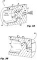
Fig. 3A is a cross-sectional perspective view of an embodiment of a nozzle tip in accordance with this disclosure; -
Fig. 3B is a cross-sectional perspective view of the embodiment ofFig. 3A ; -
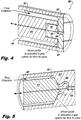
Fig. 4 is a cross-sectional perspective view of an embodiment of a fluid spray nozzle in accordance with this disclosure; and -
Fig. 5 is a cross-sectional perspective view of an embodiment of a fluid spray nozzle in accordance with this disclosure. - Reference will now be made to the drawings wherein like reference numerals identify similar structural features or aspects of the subject disclosure. For purposes of explanation and illustration, and not limitation, an illustrative view of an embodiment of a nozzle tip in accordance with the disclosure is shown in
Fig. 1A and is designated generally byreference character 100. Other embodiments and/or aspects of this disclosure are shown inFigs. 1B-5 . The systems and methods described herein can be used to reduce time to develop atomized spray and to simplify nozzle assemblies. - Referring to
Figs. 1A-1C , a fluidspray nozzle tip 100 includes afeed hole body 101 that defines one or more of feed holes 103 and a pintle sealingsurface body 105 extending from thefeed hole body 101 and configured to allow a pintle (e.g., as shown inFigs. 4 and/or 5) to seal against a sealingsurface 107 thereof. At least one of thefeed hole body 101 and the pintle sealingsurface body 105 define aspray outlet 109 in direct fluid communication with the plurality of feed holes 103 without an upstream spin chamber (e.g., a spin chamber between the feed holes 103 and thespray outlet 109 that is normally included in traditional systems). A spin chamber is traditionally placed before the outlet to induce swirl in the flow before it enters the outlet and has a different diameter than the outlet (e.g., a larger diameter) and feeds into the outlet. - The
spray outlet 109 can be centrally located (e.g., coaxial with the centerline of the tip 100) or in any other suitable position. Thespray outlet 109 can include any suitable opening edge 111 (e.g., sharp to cause narrower spray angle, angled (beveled) edge for wider spray angle). Thespray outlet 109 can have a constant flow area. For example, thespray outlet 109 can be cylindrical. Any other suitable shape and/or dimensions (e.g., 1 to 1 diameter to length) for thespray outlet 109 is contemplated herein. - As shown, in certain embodiments, the
spray outlet 109 can be defined through pintle sealingsurface body 105 and partly into thefeed hole body 101. As shown inFig. 1A , the feed holes 103 are defined at a non-normal angle relative to centerline axis of thenozzle tip 100 to meet thespray outlet 109. Referring toFig. 2A , in certain embodiments which do not fall within the scope of the invention, the feed holes 203 of anozzle 200 can be defined at normal angle relative to centerline axis to meet thespray outlet 109. In certain arrangements which do not fall within the scope of the invention, where there are a sufficiently high number of feed holes 209, to have a clean intersection (such that there are no peaks or sharp edges formed within the spray outlet 109) of thespray outlet 109, the feed holes 209 may need to be perpendicular to the centerline axis. - As shown in
Figs. 1A-2C , in certain embodiments, the feed holes 103, 203 can be straight. Any other suitable shape (e.g., a non-linear flow channel) is contemplated herein. The feed holes 103, 203 can be offset from centerline to cause swirling inspray outlet 109. - The pintle sealing
surface body 105 can define a flange having a larger dimension from the centerline than thefeed hole body 101. Thespray outlet 109 can spray from the pintle sealingsurface body 105 as shown inFigs. 1A and2A , or from any other suitable location. - Referring now to
Figs. 3A and 3B , in certain embodiments, anozzle 300 can include feedholes 303 that are recessed from sealingsurface 307 such that sealingsurface 307 extends over the feed holes 303. As shown, the sealingsurface 307 can be angled instead of flat. Any suitable shape of the sealingsurface - In certain embodiments, the feed holes 303 have a non-linear shape (e.g., tentacle shape with curves in one or more dimensions), however, any suitably shaped flow channels are contemplated herein. The feed holes 303 can meet the
outlet 109 offset from the centerline to cause swirling in theoutlet 109 and/or can be meet at a normal angle or at any suitable tilt angle. - Referring to
Figs. 1A-3B , in certain embodiments, thefeed hole body surface body 105, 305 (e.g., additively manufactured, casted). It is contemplated that thefeed hole body surface body - As shown in
Figs. 1A-2C andFig. 4 , thefeed hole body 101 can be shaped to be surrounded by apintle 413 to allow thepintle 413 to interact with thepintle sealing surface 107 to prevent flow to the feed holes 103, 203. In certain embodiments, referring toFigs. 3A, 3B , andFig. 5 , the sealingsurface body 105 can include acavity 315 configured to receive apintle 513 to allow thepintle 513 to interact with thepintle sealing surface 307 to prevent flow to the feed holes 303. - In accordance with at least one aspect of this disclosure, referring to
Fig. 4 , afluid spray nozzle 400 includes ahousing 417 defining aflow cavity 419. Any suitable embodiment of a nozzle tip (e.g.,tip 100, 200) as described above can be disposed at an end of thehousing 417. Apintle 413 is disposed within theflow cavity 419 and is configured to axially actuate therein between an open position where the feed holes 103 are in fluid communication with theflow cavity 419 and a closed position (e.g., as shown inFig. 4 ) where thepintle 413 interacts with thepintle sealing surface 107 to seal the feed holes 103 from theflow cavity 419. - In certain embodiments, the
nozzle tip 103 can be integral with thehousing 417. For example,Fig. 5 shows thenozzle tip 300 ofFigs. 3A and 3B where the sealingsurface body 305 defines acavity 315 that can receive apintle 513. - As described above, feed holes directly intersect the spray orifice at the upstream end, without a spin-chamber, which allows rapid development of a swirling flow-field and a corresponding conical spray. Feed holes offset from the centerline can create spin for atomizing quickly. Embodiments include a single piece structure that has a single orifice that causes swirling and spraying. Certain embodiments can be additively manufactured which can allow for any suitable structures and flow channels.
- Certain embodiments provide a means to very rapidly form a fully-developed conical spray. This can be particularly advantageous in applications where the injector (spray) is duty-cycled on and off, frequently (e.g., in SCR NOx reduction systems). Typical pressure-swirl atomizers have offset holes/slots which feed an upstream spin-chamber to establish a swirling flow-field, which then passes through a smaller diameter orifice and forms a finely atomized conical spray. Filling this spin-chamber and establishing the swirling flow-field takes time, and during this time the spray may or may not be conical and is typically very poorly atomized. Embodiments eliminate the spin-chamber and feed offset holes/slots directly into the orifice. This permits very rapid spray cone development with good atomization. Embodiments can be used as swirler for any suitable system and is not limited to use in SCR systems, or even for rapid spray development.
Claims (15)
- A fluid spray nozzle tip (100), comprising:a feed hole body (101) that defines at least one feed hole (103) and a spray outlet (109),wherein the at least one feed hole (103) is a plurality of feed holes,characterised by the plurality of feed holes being in direct fluid communication with the spray outlet (109) without also being in fluid communication with an upstream spin chamber,wherein the tip further includes a pintle sealing surface body (105) extending from the feed hole body (101) and configured to allow a pintle (413) to seal against a sealing surface (107) thereof,wherein the plurality of feed holes are defined at a non-normal angle relative to a centerline axis of the nozzle tip where the plurality of feed holes intersect with the spray outlet (109).
- The nozzle tip (100) of claim 1, wherein the spray outlet (109) has a constant cross sectional area over a full longitudinal dimension of the spray outlet (109).
- The nozzle tip (100) of claim 2, wherein the spray outlet (109) is cylindrical.
- The nozzle tip (100) of claim 1, 2 or 3, wherein the spray outlet (109) is defined through pintle sealing surface body (105) and partly into the feed hole body (101).
- The nozzle tip (100) of any of claims 1 to 4, wherein the feed holes (103) are straight.
- The nozzle tip (100) of any of claims 1 to 5, wherein the feed holes (103) are offset from centerline of the spray outlet (109) to cause swirling in spray outlet (109).
- The nozzle tip (100) of claim 6, wherein each feed hole (103) intersects at least one other feed hole (103) in addition to intersecting with the spray outlet (109).
- The nozzle tip (100) of claim 6 or 7, wherein the each feed hole (103) defines a feed hole axis and the spray outlet (109) defines a spray outlet axis, wherein the feed hole axis is skewed relative to the spray outlet axis.
- The nozzle tip (100) of any of claims 1 to 8, wherein the pintle sealing surface body (105) defines a flange having a larger dimension from the centerline than the feed hole body (101).
- The nozzle tip (100) of claim 9, wherein the spray outlet (109) effuses from the pintle sealing surface body (105).
- The nozzle tip (100) of any of claims 1 to 10, wherein the feed holes (103) are recessed inwardly from the sealing surface (107) such that the sealing surface extends at least partially over the feed holes (103).
- The nozzle tip (100) of claim 11, wherein the feed holes (103) have a non-linear shape.
- The nozzle tip (100) of claim 12, wherein the non-linear shape is tentacle shaped.
- The nozzle tip (100) of any of claims 1 to 13, wherein the feed hole body (101) is integral with the pintle sealing surface body (105),
wherein, optionally, the feed hole body (101) is shaped to be surrounded by a pintle (413) to allow the pintle to seal against the pintle sealing surface (105) to prevent flow to the feed holes (103), and/or wherein, optionally, the sealing surface body (105) includes a cavity configured to receive a pintle (413) to allow the pintle to interact with the pintle sealing surface (105) to prevent flow to the feed holes (103). - A diesel exhaust fluid spray nozzle for a selective catalyst reduction system, the nozzle comprising:a housing defining a flow cavity;a nozzle tip (100) disposed at an end of the housing, comprising:a feed hole body (101) that defines a plurality of feed holes (103); andcharacterised by a pintle sealing surface body (105) extending from the feed hole body (101) and configured to allow a pintle (413) to seal against a sealing surface (107) thereof,wherein at least one of the feed hole body (101) and the pintle sealing surface body (105) define a spray outlet (109) in direct fluid communication with the plurality of feed holes (103) without an upstream spin chamber; anda pintle (413) disposed within the flow cavity and configured to axially actuate therein between an open position where the feed holes (103) are in fluid communication with the flow cavity, and a closed position where the pintle interacts with the pintle sealing surface (105) to seal the feed holes (103) from the flow cavity;wherein the feed holes (103) are defined at a non-normal angle relative to a centerline axis of the nozzle tip (100) where the at least one feed hole (103) intersects with the spray outlet (109).
Applications Claiming Priority (1)
| Application Number | Priority Date | Filing Date | Title |
|---|---|---|---|
| US15/653,931 US10807108B2 (en) | 2017-07-19 | 2017-07-19 | Fluid spray injectors |
Publications (2)
| Publication Number | Publication Date |
|---|---|
| EP3431730A1 EP3431730A1 (en) | 2019-01-23 |
| EP3431730B1 true EP3431730B1 (en) | 2021-01-13 |
Family
ID=62873208
Family Applications (1)
| Application Number | Title | Priority Date | Filing Date |
|---|---|---|---|
| EP18181620.8A Active EP3431730B1 (en) | 2017-07-19 | 2018-07-04 | Fluid spray injectors |
Country Status (2)
| Country | Link |
|---|---|
| US (1) | US10807108B2 (en) |
| EP (1) | EP3431730B1 (en) |
Families Citing this family (4)
| Publication number | Priority date | Publication date | Assignee | Title |
|---|---|---|---|---|
| WO2019126457A1 (en) * | 2017-12-21 | 2019-06-27 | 3M Innovative Properties Company | Fluid injector nozzle with swirl chamber |
| CN113617545B (en) * | 2021-09-07 | 2022-05-20 | 昆山开拓者喷雾系统科技有限公司 | Anti-blocking type spray rod and spraying device with same |
| US12618374B2 (en) | 2023-09-20 | 2026-05-05 | Collins Engine Nozzles, Inc. | Swirl valves |
| CN117469016A (en) * | 2023-11-23 | 2024-01-30 | 江苏大学 | A geometrically induced double-layer swirl single-hole urea nozzle with simple processing technology |
Family Cites Families (6)
| Publication number | Priority date | Publication date | Assignee | Title |
|---|---|---|---|---|
| US2037645A (en) * | 1933-09-19 | 1936-04-14 | Peabody Engineering Corp | Wide range mechanical atomizer |
| US3100084A (en) * | 1961-08-01 | 1963-08-06 | Gulf Research Development Co | Constant flow rate fuel injection nozzle |
| US4087050A (en) | 1975-09-18 | 1978-05-02 | Ishikawajima-Harima Jukogyo Kabushiki Kaisha | Swirl type pressure fuel atomizer |
| US6024301A (en) | 1998-10-16 | 2000-02-15 | Combustion Components Associates, Inc. | Low NOx liquid fuel oil atomizer spray plate and fabrication method thereof |
| US7735756B2 (en) | 2006-04-12 | 2010-06-15 | Combustion Components Associates, Inc. | Advanced mechanical atomization for oil burners |
| US8549842B2 (en) | 2009-12-01 | 2013-10-08 | GM Global Technology Operations LLC | Air assisted injector, and injection system and exhaust treatment system incorporating the same |
-
2017
- 2017-07-19 US US15/653,931 patent/US10807108B2/en active Active
-
2018
- 2018-07-04 EP EP18181620.8A patent/EP3431730B1/en active Active
Non-Patent Citations (1)
| Title |
|---|
| None * |
Also Published As
| Publication number | Publication date |
|---|---|
| EP3431730A1 (en) | 2019-01-23 |
| US10807108B2 (en) | 2020-10-20 |
| US20190022673A1 (en) | 2019-01-24 |
Similar Documents
| Publication | Publication Date | Title |
|---|---|---|
| EP3431730A1 (en) | Fluid spray injectors | |
| US6783085B2 (en) | Fuel injector swirl nozzle assembly | |
| US6427932B1 (en) | Fuel injection nozzle for an internal combustion engine | |
| US4771948A (en) | Combination of a fuel injection valve and a nozzle | |
| EP1042604B1 (en) | Flat needle for pressurized swirl fuel injector | |
| KR950003762B1 (en) | Fuel injection valve | |
| KR101767357B1 (en) | Nozzle body and fuel injection valve | |
| JP4218696B2 (en) | Fuel injection nozzle | |
| JP4024144B2 (en) | Fuel injection device | |
| US7011257B2 (en) | Fuel injection valve | |
| CN110023616B (en) | Fuel injection device | |
| KR100471686B1 (en) | Two fluid nozzles | |
| US5878962A (en) | Pressure swirl injector with angled cone spray for fuel injection | |
| JPWO2007013165A1 (en) | Fuel injection valve | |
| US6422198B1 (en) | Pressure atomizer having multiple orifices and turbulent generation feature | |
| KR20170020447A (en) | Injection device | |
| KR101907764B1 (en) | Nozzle assembly and fuel injection valve for a combustion engine | |
| EP3985242A1 (en) | Liquid injection nozzle | |
| KR100419183B1 (en) | Fluid injection nozzle | |
| EP3279439A1 (en) | Scr doser spray atomization | |
| EP2798167B1 (en) | Device for introducing a reductant | |
| KR101741336B1 (en) | Internal impingement type pintle injector | |
| JP2503551Y2 (en) | Fuel injection device for internal combustion engine | |
| JP3132283B2 (en) | Liquid injection valve | |
| US20030025006A1 (en) | Impinging sheet atomizer nozzle |
Legal Events
| Date | Code | Title | Description |
|---|---|---|---|
| PUAI | Public reference made under article 153(3) epc to a published international application that has entered the european phase |
Free format text: ORIGINAL CODE: 0009012 |
|
| STAA | Information on the status of an ep patent application or granted ep patent |
Free format text: STATUS: THE APPLICATION HAS BEEN PUBLISHED |
|
| AK | Designated contracting states |
Kind code of ref document: A1 Designated state(s): AL AT BE BG CH CY CZ DE DK EE ES FI FR GB GR HR HU IE IS IT LI LT LU LV MC MK MT NL NO PL PT RO RS SE SI SK SM TR |
|
| AX | Request for extension of the european patent |
Extension state: BA ME |
|
| STAA | Information on the status of an ep patent application or granted ep patent |
Free format text: STATUS: REQUEST FOR EXAMINATION WAS MADE |
|
| 17P | Request for examination filed |
Effective date: 20190723 |
|
| RBV | Designated contracting states (corrected) |
Designated state(s): AL AT BE BG CH CY CZ DE DK EE ES FI FR GB GR HR HU IE IS IT LI LT LU LV MC MK MT NL NO PL PT RO RS SE SI SK SM TR |
|
| STAA | Information on the status of an ep patent application or granted ep patent |
Free format text: STATUS: EXAMINATION IS IN PROGRESS |
|
| 17Q | First examination report despatched |
Effective date: 20191122 |
|
| GRAP | Despatch of communication of intention to grant a patent |
Free format text: ORIGINAL CODE: EPIDOSNIGR1 |
|
| STAA | Information on the status of an ep patent application or granted ep patent |
Free format text: STATUS: GRANT OF PATENT IS INTENDED |
|
| INTG | Intention to grant announced |
Effective date: 20200804 |
|
| GRAS | Grant fee paid |
Free format text: ORIGINAL CODE: EPIDOSNIGR3 |
|
| GRAA | (expected) grant |
Free format text: ORIGINAL CODE: 0009210 |
|
| STAA | Information on the status of an ep patent application or granted ep patent |
Free format text: STATUS: THE PATENT HAS BEEN GRANTED |
|
| AK | Designated contracting states |
Kind code of ref document: B1 Designated state(s): AL AT BE BG CH CY CZ DE DK EE ES FI FR GB GR HR HU IE IS IT LI LT LU LV MC MK MT NL NO PL PT RO RS SE SI SK SM TR |
|
| REG | Reference to a national code |
Ref country code: GB Ref legal event code: FG4D |
|
| REG | Reference to a national code |
Ref country code: CH Ref legal event code: EP |
|
| REG | Reference to a national code |
Ref country code: IE Ref legal event code: FG4D |
|
| REG | Reference to a national code |
Ref country code: DE Ref legal event code: R096 Ref document number: 602018011754 Country of ref document: DE |
|
| REG | Reference to a national code |
Ref country code: AT Ref legal event code: REF Ref document number: 1354718 Country of ref document: AT Kind code of ref document: T Effective date: 20210215 |
|
| REG | Reference to a national code |
Ref country code: AT Ref legal event code: MK05 Ref document number: 1354718 Country of ref document: AT Kind code of ref document: T Effective date: 20210113 |
|
| REG | Reference to a national code |
Ref country code: NL Ref legal event code: MP Effective date: 20210113 |
|
| REG | Reference to a national code |
Ref country code: LT Ref legal event code: MG9D |
|
| PG25 | Lapsed in a contracting state [announced via postgrant information from national office to epo] |
Ref country code: HR Free format text: LAPSE BECAUSE OF FAILURE TO SUBMIT A TRANSLATION OF THE DESCRIPTION OR TO PAY THE FEE WITHIN THE PRESCRIBED TIME-LIMIT Effective date: 20210113 Ref country code: FI Free format text: LAPSE BECAUSE OF FAILURE TO SUBMIT A TRANSLATION OF THE DESCRIPTION OR TO PAY THE FEE WITHIN THE PRESCRIBED TIME-LIMIT Effective date: 20210113 Ref country code: GR Free format text: LAPSE BECAUSE OF FAILURE TO SUBMIT A TRANSLATION OF THE DESCRIPTION OR TO PAY THE FEE WITHIN THE PRESCRIBED TIME-LIMIT Effective date: 20210414 Ref country code: BG Free format text: LAPSE BECAUSE OF FAILURE TO SUBMIT A TRANSLATION OF THE DESCRIPTION OR TO PAY THE FEE WITHIN THE PRESCRIBED TIME-LIMIT Effective date: 20210413 Ref country code: PT Free format text: LAPSE BECAUSE OF FAILURE TO SUBMIT A TRANSLATION OF THE DESCRIPTION OR TO PAY THE FEE WITHIN THE PRESCRIBED TIME-LIMIT Effective date: 20210513 Ref country code: NO Free format text: LAPSE BECAUSE OF FAILURE TO SUBMIT A TRANSLATION OF THE DESCRIPTION OR TO PAY THE FEE WITHIN THE PRESCRIBED TIME-LIMIT Effective date: 20210413 Ref country code: LT Free format text: LAPSE BECAUSE OF FAILURE TO SUBMIT A TRANSLATION OF THE DESCRIPTION OR TO PAY THE FEE WITHIN THE PRESCRIBED TIME-LIMIT Effective date: 20210113 |
|
| PG25 | Lapsed in a contracting state [announced via postgrant information from national office to epo] |
Ref country code: SE Free format text: LAPSE BECAUSE OF FAILURE TO SUBMIT A TRANSLATION OF THE DESCRIPTION OR TO PAY THE FEE WITHIN THE PRESCRIBED TIME-LIMIT Effective date: 20210113 Ref country code: RS Free format text: LAPSE BECAUSE OF FAILURE TO SUBMIT A TRANSLATION OF THE DESCRIPTION OR TO PAY THE FEE WITHIN THE PRESCRIBED TIME-LIMIT Effective date: 20210113 Ref country code: LV Free format text: LAPSE BECAUSE OF FAILURE TO SUBMIT A TRANSLATION OF THE DESCRIPTION OR TO PAY THE FEE WITHIN THE PRESCRIBED TIME-LIMIT Effective date: 20210113 Ref country code: PL Free format text: LAPSE BECAUSE OF FAILURE TO SUBMIT A TRANSLATION OF THE DESCRIPTION OR TO PAY THE FEE WITHIN THE PRESCRIBED TIME-LIMIT Effective date: 20210113 Ref country code: AT Free format text: LAPSE BECAUSE OF FAILURE TO SUBMIT A TRANSLATION OF THE DESCRIPTION OR TO PAY THE FEE WITHIN THE PRESCRIBED TIME-LIMIT Effective date: 20210113 |
|
| PG25 | Lapsed in a contracting state [announced via postgrant information from national office to epo] |
Ref country code: IS Free format text: LAPSE BECAUSE OF FAILURE TO SUBMIT A TRANSLATION OF THE DESCRIPTION OR TO PAY THE FEE WITHIN THE PRESCRIBED TIME-LIMIT Effective date: 20210513 |
|
| REG | Reference to a national code |
Ref country code: DE Ref legal event code: R097 Ref document number: 602018011754 Country of ref document: DE |
|
| PG25 | Lapsed in a contracting state [announced via postgrant information from national office to epo] |
Ref country code: SM Free format text: LAPSE BECAUSE OF FAILURE TO SUBMIT A TRANSLATION OF THE DESCRIPTION OR TO PAY THE FEE WITHIN THE PRESCRIBED TIME-LIMIT Effective date: 20210113 Ref country code: EE Free format text: LAPSE BECAUSE OF FAILURE TO SUBMIT A TRANSLATION OF THE DESCRIPTION OR TO PAY THE FEE WITHIN THE PRESCRIBED TIME-LIMIT Effective date: 20210113 Ref country code: CZ Free format text: LAPSE BECAUSE OF FAILURE TO SUBMIT A TRANSLATION OF THE DESCRIPTION OR TO PAY THE FEE WITHIN THE PRESCRIBED TIME-LIMIT Effective date: 20210113 |
|
| PLBE | No opposition filed within time limit |
Free format text: ORIGINAL CODE: 0009261 |
|
| STAA | Information on the status of an ep patent application or granted ep patent |
Free format text: STATUS: NO OPPOSITION FILED WITHIN TIME LIMIT |
|
| PG25 | Lapsed in a contracting state [announced via postgrant information from national office to epo] |
Ref country code: RO Free format text: LAPSE BECAUSE OF FAILURE TO SUBMIT A TRANSLATION OF THE DESCRIPTION OR TO PAY THE FEE WITHIN THE PRESCRIBED TIME-LIMIT Effective date: 20210113 Ref country code: DK Free format text: LAPSE BECAUSE OF FAILURE TO SUBMIT A TRANSLATION OF THE DESCRIPTION OR TO PAY THE FEE WITHIN THE PRESCRIBED TIME-LIMIT Effective date: 20210113 Ref country code: SK Free format text: LAPSE BECAUSE OF FAILURE TO SUBMIT A TRANSLATION OF THE DESCRIPTION OR TO PAY THE FEE WITHIN THE PRESCRIBED TIME-LIMIT Effective date: 20210113 |
|
| 26N | No opposition filed |
Effective date: 20211014 |
|
| PG25 | Lapsed in a contracting state [announced via postgrant information from national office to epo] |
Ref country code: AL Free format text: LAPSE BECAUSE OF FAILURE TO SUBMIT A TRANSLATION OF THE DESCRIPTION OR TO PAY THE FEE WITHIN THE PRESCRIBED TIME-LIMIT Effective date: 20210113 Ref country code: ES Free format text: LAPSE BECAUSE OF FAILURE TO SUBMIT A TRANSLATION OF THE DESCRIPTION OR TO PAY THE FEE WITHIN THE PRESCRIBED TIME-LIMIT Effective date: 20210113 |
|
| PG25 | Lapsed in a contracting state [announced via postgrant information from national office to epo] |
Ref country code: SI Free format text: LAPSE BECAUSE OF FAILURE TO SUBMIT A TRANSLATION OF THE DESCRIPTION OR TO PAY THE FEE WITHIN THE PRESCRIBED TIME-LIMIT Effective date: 20210113 |
|
| REG | Reference to a national code |
Ref country code: CH Ref legal event code: PL |
|
| PG25 | Lapsed in a contracting state [announced via postgrant information from national office to epo] |
Ref country code: MC Free format text: LAPSE BECAUSE OF FAILURE TO SUBMIT A TRANSLATION OF THE DESCRIPTION OR TO PAY THE FEE WITHIN THE PRESCRIBED TIME-LIMIT Effective date: 20210113 |
|
| REG | Reference to a national code |
Ref country code: BE Ref legal event code: MM Effective date: 20210731 |
|
| PG25 | Lapsed in a contracting state [announced via postgrant information from national office to epo] |
Ref country code: LI Free format text: LAPSE BECAUSE OF NON-PAYMENT OF DUE FEES Effective date: 20210731 Ref country code: IT Free format text: LAPSE BECAUSE OF FAILURE TO SUBMIT A TRANSLATION OF THE DESCRIPTION OR TO PAY THE FEE WITHIN THE PRESCRIBED TIME-LIMIT Effective date: 20210113 Ref country code: CH Free format text: LAPSE BECAUSE OF NON-PAYMENT OF DUE FEES Effective date: 20210731 |
|
| PG25 | Lapsed in a contracting state [announced via postgrant information from national office to epo] |
Ref country code: IS Free format text: LAPSE BECAUSE OF FAILURE TO SUBMIT A TRANSLATION OF THE DESCRIPTION OR TO PAY THE FEE WITHIN THE PRESCRIBED TIME-LIMIT Effective date: 20210513 Ref country code: LU Free format text: LAPSE BECAUSE OF NON-PAYMENT OF DUE FEES Effective date: 20210704 |
|
| PG25 | Lapsed in a contracting state [announced via postgrant information from national office to epo] |
Ref country code: IE Free format text: LAPSE BECAUSE OF NON-PAYMENT OF DUE FEES Effective date: 20210704 Ref country code: BE Free format text: LAPSE BECAUSE OF NON-PAYMENT OF DUE FEES Effective date: 20210731 |
|
| PG25 | Lapsed in a contracting state [announced via postgrant information from national office to epo] |
Ref country code: NL Free format text: LAPSE BECAUSE OF NON-PAYMENT OF DUE FEES Effective date: 20210113 Ref country code: CY Free format text: LAPSE BECAUSE OF FAILURE TO SUBMIT A TRANSLATION OF THE DESCRIPTION OR TO PAY THE FEE WITHIN THE PRESCRIBED TIME-LIMIT Effective date: 20210113 |
|
| P01 | Opt-out of the competence of the unified patent court (upc) registered |
Effective date: 20230530 |
|
| PG25 | Lapsed in a contracting state [announced via postgrant information from national office to epo] |
Ref country code: HU Free format text: LAPSE BECAUSE OF FAILURE TO SUBMIT A TRANSLATION OF THE DESCRIPTION OR TO PAY THE FEE WITHIN THE PRESCRIBED TIME-LIMIT; INVALID AB INITIO Effective date: 20180704 |
|
| PG25 | Lapsed in a contracting state [announced via postgrant information from national office to epo] |
Ref country code: MK Free format text: LAPSE BECAUSE OF FAILURE TO SUBMIT A TRANSLATION OF THE DESCRIPTION OR TO PAY THE FEE WITHIN THE PRESCRIBED TIME-LIMIT Effective date: 20210113 |
|
| PG25 | Lapsed in a contracting state [announced via postgrant information from national office to epo] |
Ref country code: MT Free format text: LAPSE BECAUSE OF FAILURE TO SUBMIT A TRANSLATION OF THE DESCRIPTION OR TO PAY THE FEE WITHIN THE PRESCRIBED TIME-LIMIT Effective date: 20210113 |
|
| PGFP | Annual fee paid to national office [announced via postgrant information from national office to epo] |
Ref country code: GB Payment date: 20250619 Year of fee payment: 8 |
|
| PGFP | Annual fee paid to national office [announced via postgrant information from national office to epo] |
Ref country code: FR Payment date: 20250620 Year of fee payment: 8 |
|
| PGFP | Annual fee paid to national office [announced via postgrant information from national office to epo] |
Ref country code: DE Payment date: 20250620 Year of fee payment: 8 |
|
| PG25 | Lapsed in a contracting state [announced via postgrant information from national office to epo] |
Ref country code: TR Free format text: LAPSE BECAUSE OF FAILURE TO SUBMIT A TRANSLATION OF THE DESCRIPTION OR TO PAY THE FEE WITHIN THE PRESCRIBED TIME-LIMIT Effective date: 20210113 |