EP3431721A1 - Gas turbine engine components and assembly thereof - Google Patents
Gas turbine engine components and assembly thereof Download PDFInfo
- Publication number
- EP3431721A1 EP3431721A1 EP18184235.2A EP18184235A EP3431721A1 EP 3431721 A1 EP3431721 A1 EP 3431721A1 EP 18184235 A EP18184235 A EP 18184235A EP 3431721 A1 EP3431721 A1 EP 3431721A1
- Authority
- EP
- European Patent Office
- Prior art keywords
- component
- cooling plate
- fluid
- loading ram
- cooling
- Prior art date
- Legal status (The legal status is an assumption and is not a legal conclusion. Google has not performed a legal analysis and makes no representation as to the accuracy of the status listed.)
- Granted
Links
Images




Classifications
-
- F—MECHANICAL ENGINEERING; LIGHTING; HEATING; WEAPONS; BLASTING
- F01—MACHINES OR ENGINES IN GENERAL; ENGINE PLANTS IN GENERAL; STEAM ENGINES
- F01D—NON-POSITIVE DISPLACEMENT MACHINES OR ENGINES, e.g. STEAM TURBINES
- F01D25/00—Component parts, details, or accessories, not provided for in, or of interest apart from, other groups
- F01D25/16—Arrangement of bearings; Supporting or mounting bearings in casings
- F01D25/162—Bearing supports
-
- B—PERFORMING OPERATIONS; TRANSPORTING
- B23—MACHINE TOOLS; METAL-WORKING NOT OTHERWISE PROVIDED FOR
- B23P—METAL-WORKING NOT OTHERWISE PROVIDED FOR; COMBINED OPERATIONS; UNIVERSAL MACHINE TOOLS
- B23P11/00—Connecting or disconnecting metal parts or objects by metal-working techniques not otherwise provided for
- B23P11/02—Connecting or disconnecting metal parts or objects by metal-working techniques not otherwise provided for by first expanding and then shrinking or vice versa, e.g. by using pressure fluids; by making force fits
- B23P11/025—Connecting or disconnecting metal parts or objects by metal-working techniques not otherwise provided for by first expanding and then shrinking or vice versa, e.g. by using pressure fluids; by making force fits by using heat or cold
-
- F—MECHANICAL ENGINEERING; LIGHTING; HEATING; WEAPONS; BLASTING
- F01—MACHINES OR ENGINES IN GENERAL; ENGINE PLANTS IN GENERAL; STEAM ENGINES
- F01D—NON-POSITIVE DISPLACEMENT MACHINES OR ENGINES, e.g. STEAM TURBINES
- F01D25/00—Component parts, details, or accessories, not provided for in, or of interest apart from, other groups
- F01D25/08—Cooling; Heating; Heat-insulation
- F01D25/12—Cooling
- F01D25/125—Cooling of bearings
-
- F—MECHANICAL ENGINEERING; LIGHTING; HEATING; WEAPONS; BLASTING
- F01—MACHINES OR ENGINES IN GENERAL; ENGINE PLANTS IN GENERAL; STEAM ENGINES
- F01D—NON-POSITIVE DISPLACEMENT MACHINES OR ENGINES, e.g. STEAM TURBINES
- F01D25/00—Component parts, details, or accessories, not provided for in, or of interest apart from, other groups
- F01D25/16—Arrangement of bearings; Supporting or mounting bearings in casings
-
- F—MECHANICAL ENGINEERING; LIGHTING; HEATING; WEAPONS; BLASTING
- F01—MACHINES OR ENGINES IN GENERAL; ENGINE PLANTS IN GENERAL; STEAM ENGINES
- F01D—NON-POSITIVE DISPLACEMENT MACHINES OR ENGINES, e.g. STEAM TURBINES
- F01D25/00—Component parts, details, or accessories, not provided for in, or of interest apart from, other groups
- F01D25/28—Supporting or mounting arrangements, e.g. for turbine casing
-
- F—MECHANICAL ENGINEERING; LIGHTING; HEATING; WEAPONS; BLASTING
- F16—ENGINEERING ELEMENTS AND UNITS; GENERAL MEASURES FOR PRODUCING AND MAINTAINING EFFECTIVE FUNCTIONING OF MACHINES OR INSTALLATIONS; THERMAL INSULATION IN GENERAL
- F16C—SHAFTS; FLEXIBLE SHAFTS; ELEMENTS OR CRANKSHAFT MECHANISMS; ROTARY BODIES OTHER THAN GEARING ELEMENTS; BEARINGS
- F16C35/00—Rigid support of bearing units; Housings, e.g. caps, covers
- F16C35/04—Rigid support of bearing units; Housings, e.g. caps, covers in the case of ball or roller bearings
- F16C35/06—Mounting or dismounting of ball or roller bearings; Fixing them onto shaft or in housing
- F16C35/063—Fixing them on the shaft
-
- F—MECHANICAL ENGINEERING; LIGHTING; HEATING; WEAPONS; BLASTING
- F16—ENGINEERING ELEMENTS AND UNITS; GENERAL MEASURES FOR PRODUCING AND MAINTAINING EFFECTIVE FUNCTIONING OF MACHINES OR INSTALLATIONS; THERMAL INSULATION IN GENERAL
- F16C—SHAFTS; FLEXIBLE SHAFTS; ELEMENTS OR CRANKSHAFT MECHANISMS; ROTARY BODIES OTHER THAN GEARING ELEMENTS; BEARINGS
- F16C43/00—Assembling bearings
-
- F—MECHANICAL ENGINEERING; LIGHTING; HEATING; WEAPONS; BLASTING
- F05—INDEXING SCHEMES RELATING TO ENGINES OR PUMPS IN VARIOUS SUBCLASSES OF CLASSES F01-F04
- F05D—INDEXING SCHEME FOR ASPECTS RELATING TO NON-POSITIVE-DISPLACEMENT MACHINES OR ENGINES, GAS-TURBINES OR JET-PROPULSION PLANTS
- F05D2220/00—Application
- F05D2220/30—Application in turbines
- F05D2220/32—Application in turbines in gas turbines
-
- F—MECHANICAL ENGINEERING; LIGHTING; HEATING; WEAPONS; BLASTING
- F05—INDEXING SCHEMES RELATING TO ENGINES OR PUMPS IN VARIOUS SUBCLASSES OF CLASSES F01-F04
- F05D—INDEXING SCHEME FOR ASPECTS RELATING TO NON-POSITIVE-DISPLACEMENT MACHINES OR ENGINES, GAS-TURBINES OR JET-PROPULSION PLANTS
- F05D2240/00—Components
- F05D2240/50—Bearings
-
- F—MECHANICAL ENGINEERING; LIGHTING; HEATING; WEAPONS; BLASTING
- F05—INDEXING SCHEMES RELATING TO ENGINES OR PUMPS IN VARIOUS SUBCLASSES OF CLASSES F01-F04
- F05D—INDEXING SCHEME FOR ASPECTS RELATING TO NON-POSITIVE-DISPLACEMENT MACHINES OR ENGINES, GAS-TURBINES OR JET-PROPULSION PLANTS
- F05D2240/00—Components
- F05D2240/50—Bearings
- F05D2240/52—Axial thrust bearings
-
- F—MECHANICAL ENGINEERING; LIGHTING; HEATING; WEAPONS; BLASTING
- F05—INDEXING SCHEMES RELATING TO ENGINES OR PUMPS IN VARIOUS SUBCLASSES OF CLASSES F01-F04
- F05D—INDEXING SCHEME FOR ASPECTS RELATING TO NON-POSITIVE-DISPLACEMENT MACHINES OR ENGINES, GAS-TURBINES OR JET-PROPULSION PLANTS
- F05D2240/00—Components
- F05D2240/50—Bearings
- F05D2240/54—Radial bearings
-
- F—MECHANICAL ENGINEERING; LIGHTING; HEATING; WEAPONS; BLASTING
- F16—ENGINEERING ELEMENTS AND UNITS; GENERAL MEASURES FOR PRODUCING AND MAINTAINING EFFECTIVE FUNCTIONING OF MACHINES OR INSTALLATIONS; THERMAL INSULATION IN GENERAL
- F16C—SHAFTS; FLEXIBLE SHAFTS; ELEMENTS OR CRANKSHAFT MECHANISMS; ROTARY BODIES OTHER THAN GEARING ELEMENTS; BEARINGS
- F16C2226/00—Joining parts; Fastening; Assembling or mounting parts
- F16C2226/10—Force connections, e.g. clamping
- F16C2226/14—Force connections, e.g. clamping by shrink fit, i.e. heating and shrinking part to allow assembly
-
- F—MECHANICAL ENGINEERING; LIGHTING; HEATING; WEAPONS; BLASTING
- F16—ENGINEERING ELEMENTS AND UNITS; GENERAL MEASURES FOR PRODUCING AND MAINTAINING EFFECTIVE FUNCTIONING OF MACHINES OR INSTALLATIONS; THERMAL INSULATION IN GENERAL
- F16C—SHAFTS; FLEXIBLE SHAFTS; ELEMENTS OR CRANKSHAFT MECHANISMS; ROTARY BODIES OTHER THAN GEARING ELEMENTS; BEARINGS
- F16C2360/00—Engines or pumps
- F16C2360/23—Gas turbine engines
-
- F—MECHANICAL ENGINEERING; LIGHTING; HEATING; WEAPONS; BLASTING
- F16—ENGINEERING ELEMENTS AND UNITS; GENERAL MEASURES FOR PRODUCING AND MAINTAINING EFFECTIVE FUNCTIONING OF MACHINES OR INSTALLATIONS; THERMAL INSULATION IN GENERAL
- F16C—SHAFTS; FLEXIBLE SHAFTS; ELEMENTS OR CRANKSHAFT MECHANISMS; ROTARY BODIES OTHER THAN GEARING ELEMENTS; BEARINGS
- F16C35/00—Rigid support of bearing units; Housings, e.g. caps, covers
- F16C35/04—Rigid support of bearing units; Housings, e.g. caps, covers in the case of ball or roller bearings
- F16C35/06—Mounting or dismounting of ball or roller bearings; Fixing them onto shaft or in housing
-
- Y—GENERAL TAGGING OF NEW TECHNOLOGICAL DEVELOPMENTS; GENERAL TAGGING OF CROSS-SECTIONAL TECHNOLOGIES SPANNING OVER SEVERAL SECTIONS OF THE IPC; TECHNICAL SUBJECTS COVERED BY FORMER USPC CROSS-REFERENCE ART COLLECTIONS [XRACs] AND DIGESTS
- Y02—TECHNOLOGIES OR APPLICATIONS FOR MITIGATION OR ADAPTATION AGAINST CLIMATE CHANGE
- Y02T—CLIMATE CHANGE MITIGATION TECHNOLOGIES RELATED TO TRANSPORTATION
- Y02T50/00—Aeronautics or air transport
- Y02T50/60—Efficient propulsion technologies, e.g. for aircraft
Definitions
- FIG. 2 illustrates a system 200 that includes a seal 206, a first bearing 212a, a spacer 218, and a second bearing 212b arranged relative to (e.g., radially outward from) a shaft 224.
- the first bearing 212a includes a first roller/rolling element 213a and a first race 214a and the second bearing 212b includes a second roller/rolling element 213b and a second race 214b.
- the components 206-218 are installed on the shaft 224 in the order just mentioned (e.g., left-to-right in FIG. 2 ).
- the seal 206 is installed first, then the first bearing 212a, then the spacer 218, then the second bearing 212b.
- the arrangement/positioning of components (e.g., the components 206-218) adjacent to one another about a shaft (e.g., the shaft 224) may be referred to as a "stack" herein.
- each of the components 206-218 is heated as described above and then, in turn, pressed against the prior component in the stack (e.g., the component that is to the left in FIG. 2 ) via engagement of a loading ram 240.
- the prior component in the stack e.g., the component that is to the left in FIG. 2
- that component may be pressed against a lip/shoulder 224a of the shaft 224 via the loading ram 240.
- the shoulder 224a may form a part of the stack.
- the loading ram 240 is frequently implemented as a hydraulically actuated member.
- the loading ram 240 While the loading ram 240 is engaged/applied to the component being added/assembled to the stack, the component (e.g., the second bearing 212b as shown in the example of FIG. 2 ) that the loading ram 240 interfaces to is allowed to cool to a threshold temperature. Once this threshold temperature is reached, the loading ram 240 is disengaged/removed from the stack. Maintaining the loading ram 240 in an engaged state during component cooling ensures that the component (e.g., the second bearing 212b in FIG. 2 ) remains properly seated and gaps do not form between components in the stack.
- the component e.g., the second bearing 212b in FIG. 2
- aspects of the disclosure are directed to a method for assembling components of an engine, comprising: positioning a first component adjacent to a second component such that a first surface of the first component abuts the second component, coupling a cooling plate to the first component such that a first surface of the cooling plate abuts a second surface of the first component, and coupling a loading ram to the cooling plate such that a second surface of the cooling plate abuts the loading ram.
- the method further comprises engaging the loading ram subsequent to coupling the loading ram to the cooling plate.
- the method further comprises engaging a cooling system subsequent to engaging the loading ram, where the cooling system includes the cooling plate.
- the cooling system includes a fluid source coupled to the cooling plate, and the cooling plate includes an input port, an output port, and a passage disposed between the input port and the output port, and the method further comprises receiving, by the input port, a fluid from the fluid source, and conveying, via the passage, the fluid from the input port to the output port.
- the fluid includes compressed air.
- the cooling system includes a fluid source and a nozzle, and the method further comprises receiving, by the nozzle, a first fluid from the fluid source, and transmitting, by the nozzle, a second fluid to the cooling plate.
- the nozzle includes a vortex tube with an input port and an output port, and the method further comprises receiving, by the input port, the first fluid from the fluid source, and transmitting, by the output port, the second fluid to the cooling plate.
- the first fluid has a first temperature and the second fluid has a second temperature that is less than the first temperature.
- the method further comprises heating the first component prior to positioning the first component adjacent to the second component.
- the method further comprises determining that a temperature of the first component is less than a threshold subsequent to coupling the cooling plate to the first component, and decoupling the cooling plate from the first component based on determining that the temperature of the first component is less than the threshold.
- the threshold is approximately equal to a temperature of a room where the first component is located.
- the method further comprises disengaging a cooling system based on determining that the temperature of the first component is less than the threshold, where the cooling system includes the cooling plate.
- the method further comprises measuring the temperature of the first component to determine that the temperature of the first component is less than the threshold.
- the method further comprises decoupling the loading ram from the cooling plate subsequent to coupling the loading ram to the cooling plate, and decoupling the cooling plate from the first component subsequent to decoupling the loading ram from the cooling plate.
- the method further comprises subsequent to decoupling the cooling plate from the first component, positioning a third component adjacent to the first component such that a first surface of the third component abuts the second surface of the first component, subsequent to positioning the third component adjacent to the first component, coupling the cooling plate to the third component such that the first surface of the cooling plate abuts a second surface of the third component, and subsequent to coupling the cooling plate to the third component, coupling the loading ram to the cooling plate such that the second surface of the cooling plate abuts the loading ram.
- the first component is a bearing that includes a roller and a race
- the method further comprises abutting the race to a shaft of the engine, where the second surface of the first component is a surface of the race.
- the second component is one of a seal, a spacer, or a shoulder of a shaft of the engine, and where the loading ram is hydraulically actuated.
- the method further comprises subsequent to coupling the cooling plate to the first component, applying a cooling fluid directly to the first component.
- aspects of the disclosure are directed to a system comprising: a first component, a second component positioned adjacent to the first component such that a first surface of the second component abuts the first component, a cooling plate positioned adjacent to the second component such that a first surface of the cooling plate abuts a second surface of the second component, and a loading ram coupled to a second surface of the cooling plate.
- a bearing stacking device comprising: a housing configured to surround a shaft, where the housing includes a first surface and a second surface, where the first surface is configured to abut a component disposed on the shaft, a thermal transfer apparatus configured to transfer thermal energy to or from the component, and a loading ram configured to position the first surface of the housing in axial relation to the component.
- connections are set forth between elements in the following description and in the drawings (the contents of which are incorporated in this specification by way of reference). It is noted that these connections are general and, unless specified otherwise, may be direct or indirect and that this specification is not intended to be limiting in this respect.
- a coupling between two or more entities may refer to a direct connection or an indirect connection.
- An indirect connection may incorporate one or more intervening entities or a space/gap between the entities that are being coupled to one another.
- FIG. 1 is a side cutaway illustration of a geared turbine engine 10.
- This turbine engine 10 extends along an axial centerline 12 between an upstream airflow inlet 14 and a downstream airflow exhaust 16.
- the turbine engine 10 includes a fan section 18, a compressor section 19, a combustor section 20 and a turbine section 21.
- the compressor section 19 includes a low pressure compressor (LPC) section 19A and a high pressure compressor (HPC) section 19B.
- the turbine section 21 includes a high pressure turbine (HPT) section 21A and a low pressure turbine (LPT) section 21B.
- the engine sections 18-21 are arranged sequentially along the centerline 12 within an engine housing 22.
- Each of the engine sections 18-19B, 21A and 21B includes a respective rotor 24-28.
- Each of these rotors 24-28 includes a plurality of rotor blades arranged circumferentially around and connected to one or more respective rotor disks.
- the rotor blades may be formed integral with or mechanically fastened, welded, brazed, adhered and/or otherwise attached to the respective rotor disk(s).
- the fan rotor 24 is connected to a gear train 30, for example, through a fan shaft 32.
- the gear train 30 and the LPC rotor 25 are connected to and driven by the LPT rotor 28 through a low speed shaft 33.
- the HPC rotor 26 is connected to and driven by the HPT rotor 27 through a high speed shaft 34.
- the shafts 32-34 are rotatably supported by a plurality of bearings 36; e.g., rolling element and/or thrust bearings. Each of these bearings 36 is connected to the engine housing 22 by at least one stationary structure such as, for example, an annular support strut.
- a fan drive gear system which may be incorporated as part of the gear train 30, may be used to separate the rotation of the fan rotor 24 from the rotation of the rotor 25 of the low pressure compressor section 19A and the rotor 28 of the low pressure turbine section 21B.
- FDGS fan drive gear system
- such an FDGS may allow the fan rotor 24 to rotate at a different (e.g., slower) speed relative to the rotors 25 and 28.
- the air within the core gas path 38 may be referred to as "core air”.
- the air within the bypass gas path 40 may be referred to as "bypass air”.
- the core air is directed through the engine sections 19-21, and exits the turbine engine 10 through the airflow exhaust 16 to provide forward engine thrust.
- fuel is injected into a combustion chamber 42 and mixed with compressed core air. This fuel-core air mixture is ignited to power the turbine engine 10.
- the bypass air is directed through the bypass gas path 40 and out of the turbine engine 10 through a bypass nozzle 44 to provide additional forward engine thrust. This additional forward engine thrust may account for a majority (e.g., more than 70 percent) of total engine thrust.
- at least some of the bypass air may be directed out of the turbine engine 10 through a thrust reverser to provide reverse engine thrust.
- FIG. 1 represents one possible configuration for an engine 10. Aspects of the disclosure may be applied in connection with other environments, including additional configurations for gas turbine engines. Aspects of the disclosure may be applied in connection with non-geared engines.
- the plate 320 may be made of one or more materials. For example, in some embodiments steel may be used. Steel may provide sufficient strength relative to the loads that may be encountered during assembly from, e.g., the loading ram 240, as described further below while still providing a high degree of thermal conductivity. In embodiments where load tolerances are not as much of a consideration, aluminum may be used to enhance thermal conduction (relative to steel). In some embodiments, one or more metal alloys may be used in conjunction with the plate 320.
- a nozzle may be used.
- FIG. 4 illustrates a nozzle 426a disposed between the source 426 and the port 434. While shown as a separate device, in some embodiments the nozzle 426a may be integrated with the source 426.
- the system 700 may include a bearing stacking device that includes a housing 710, a thermal transfer apparatus 720, and a loading ram 740.
- the housing 710 may include a first (e.g., forward facing) surface 710a and a second (e.g., aft facing) surface 710b.
- the housing 710 (e.g., the surface 710a) may abut the component 708.
- the housing 710 may surround the shaft 724.
- the housing 710 may contain a plurality of discontinuous exterior surfaces; for example, the surface 710a and the surface 710b may be configured for translational movement in relation to one another. Such an example of relative translational movement may occur during operation of the loading ram 740.
Landscapes
- Engineering & Computer Science (AREA)
- General Engineering & Computer Science (AREA)
- Mechanical Engineering (AREA)
- Mounting Of Bearings Or Others (AREA)
- Rolling Contact Bearings (AREA)
Abstract
Description
- Gas turbine engines, such as those which power aircraft and industrial equipment, employ a compressor to compress air that is drawn into the engine and a turbine to capture energy associated with the combustion of a fuel-air mixture. Bearings are used to support the rotational hardware of an engine. For example, bearings are used to support a shaft of the engine.
- During assembly of an engine, bearing compartment components typically have an interference fit with a shaft. In order to facilitate installation of the bearing, the bearing is heated to at least a threshold temperature that causes the bearing to grow larger than (a diameter of) the shaft so that the bearing can slide over the shaft and into a designated position. This process is repeated for other components that have an interference fit; examples of such other components include seals, spacers, oil scoops, etc.
FIG. 2 illustrates asystem 200 that includes aseal 206, a first bearing 212a, aspacer 218, and a second bearing 212b arranged relative to (e.g., radially outward from) ashaft 224. The first bearing 212a includes a first roller/rollingelement 213a and afirst race 214a and the second bearing 212b includes a second roller/rollingelement 213b and asecond race 214b. - During assembly, the components 206-218 are installed on the
shaft 224 in the order just mentioned (e.g., left-to-right inFIG. 2 ). For example, theseal 206 is installed first, then the first bearing 212a, then thespacer 218, then the second bearing 212b. The arrangement/positioning of components (e.g., the components 206-218) adjacent to one another about a shaft (e.g., the shaft 224) may be referred to as a "stack" herein. - During assembly, each of the components 206-218 is heated as described above and then, in turn, pressed against the prior component in the stack (e.g., the component that is to the left in
FIG. 2 ) via engagement of aloading ram 240. Regarding the first/left-most component in the stack (e.g., theseal 206 inFIG. 2 ), that component may be pressed against a lip/shoulder 224a of theshaft 224 via theloading ram 240. In this respect, theshoulder 224a may form a part of the stack. Theloading ram 240 is frequently implemented as a hydraulically actuated member. - While the
loading ram 240 is engaged/applied to the component being added/assembled to the stack, the component (e.g., the second bearing 212b as shown in the example ofFIG. 2 ) that theloading ram 240 interfaces to is allowed to cool to a threshold temperature. Once this threshold temperature is reached, theloading ram 240 is disengaged/removed from the stack. Maintaining theloading ram 240 in an engaged state during component cooling ensures that the component (e.g., the second bearing 212b inFIG. 2 ) remains properly seated and gaps do not form between components in the stack. - Allowing each of the components in the stack to cool represents a cost in terms of the time it takes to assemble the engine. In some instances a component may take on the order of one hour to cool to the threshold temperature. In order to mitigate/reduce this time/cost, air may be blown onto a component to accelerate the rate at which the component cools. The use of blown air may have a tendency to introduce debris to the component. As such, the practice of using blown air may not be acceptable. This is particularly true in the context of the
bearings - The following presents a simplified summary in order to provide a basic understanding of some aspects of the disclosure. The summary is not an extensive overview of the disclosure. It is neither intended to identify key or critical elements of the disclosure nor to delineate the scope of the disclosure. The following summary merely presents some concepts of the disclosure in a simplified form as a prelude to the description below.
- Aspects of the disclosure are directed to a method for assembling components of an engine, comprising: positioning a first component adjacent to a second component such that a first surface of the first component abuts the second component, coupling a cooling plate to the first component such that a first surface of the cooling plate abuts a second surface of the first component, and coupling a loading ram to the cooling plate such that a second surface of the cooling plate abuts the loading ram. In some embodiments, the method further comprises engaging the loading ram subsequent to coupling the loading ram to the cooling plate. In some embodiments, the method further comprises engaging a cooling system subsequent to engaging the loading ram, where the cooling system includes the cooling plate. In some embodiments, the cooling system includes a fluid source coupled to the cooling plate, and the cooling plate includes an input port, an output port, and a passage disposed between the input port and the output port, and the method further comprises receiving, by the input port, a fluid from the fluid source, and conveying, via the passage, the fluid from the input port to the output port. In some embodiments, the fluid includes compressed air. In some embodiments, the cooling system includes a fluid source and a nozzle, and the method further comprises receiving, by the nozzle, a first fluid from the fluid source, and transmitting, by the nozzle, a second fluid to the cooling plate. In some embodiments, the nozzle includes a vortex tube with an input port and an output port, and the method further comprises receiving, by the input port, the first fluid from the fluid source, and transmitting, by the output port, the second fluid to the cooling plate. In some embodiments, the first fluid has a first temperature and the second fluid has a second temperature that is less than the first temperature. In some embodiments, the method further comprises heating the first component prior to positioning the first component adjacent to the second component. In some embodiments, the method further comprises determining that a temperature of the first component is less than a threshold subsequent to coupling the cooling plate to the first component, and decoupling the cooling plate from the first component based on determining that the temperature of the first component is less than the threshold. In some embodiments, the threshold is approximately equal to a temperature of a room where the first component is located. In some embodiments, the method further comprises disengaging a cooling system based on determining that the temperature of the first component is less than the threshold, where the cooling system includes the cooling plate. In some embodiments, the method further comprises measuring the temperature of the first component to determine that the temperature of the first component is less than the threshold. In some embodiments, the method further comprises decoupling the loading ram from the cooling plate subsequent to coupling the loading ram to the cooling plate, and decoupling the cooling plate from the first component subsequent to decoupling the loading ram from the cooling plate. In some embodiments, the method further comprises subsequent to decoupling the cooling plate from the first component, positioning a third component adjacent to the first component such that a first surface of the third component abuts the second surface of the first component, subsequent to positioning the third component adjacent to the first component, coupling the cooling plate to the third component such that the first surface of the cooling plate abuts a second surface of the third component, and subsequent to coupling the cooling plate to the third component, coupling the loading ram to the cooling plate such that the second surface of the cooling plate abuts the loading ram. In some embodiments, the first component is a bearing that includes a roller and a race, and the method further comprises abutting the race to a shaft of the engine, where the second surface of the first component is a surface of the race. In some embodiments, the second component is one of a seal, a spacer, or a shoulder of a shaft of the engine, and where the loading ram is hydraulically actuated. In some embodiments, the method further comprises subsequent to coupling the cooling plate to the first component, applying a cooling fluid directly to the first component.
- Aspects of the disclosure are directed to a system comprising: a first component, a second component positioned adjacent to the first component such that a first surface of the second component abuts the first component, a cooling plate positioned adjacent to the second component such that a first surface of the cooling plate abuts a second surface of the second component, and a loading ram coupled to a second surface of the cooling plate.
- Aspects of the disclosure are directed to a bearing stacking device, comprising: a housing configured to surround a shaft, where the housing includes a first surface and a second surface, where the first surface is configured to abut a component disposed on the shaft, a thermal transfer apparatus configured to transfer thermal energy to or from the component, and a loading ram configured to position the first surface of the housing in axial relation to the component.
- The present disclosure is illustrated by way of example and not limited in the accompanying figures in which like reference numerals indicate similar elements. The drawing figures are not necessarily drawn to scale unless specifically indicated otherwise.
-
FIG. 1 is a side cutaway illustration of a geared turbine engine. -
FIG. 2 illustrates a block diagram of a bearing compartment system in accordance with the prior art. -
FIG. 3 illustrates a block diagram of a bearing compartment system in accordance with aspects of this disclosure. -
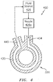
FIG. 4 illustrates a cooling system in accordance with aspects of this disclosure. -
FIG. 5 illustrates a method for assembling a component stack in accordance with aspects of this disclosure. -
FIG. 6 illustrates a vortex tube in accordance with aspects of this disclosure. -
FIG. 7 illustrates a system incorporating a bearing stacking device in accordance with aspects of this disclosure. - It is noted that various connections are set forth between elements in the following description and in the drawings (the contents of which are incorporated in this specification by way of reference). It is noted that these connections are general and, unless specified otherwise, may be direct or indirect and that this specification is not intended to be limiting in this respect. A coupling between two or more entities may refer to a direct connection or an indirect connection. An indirect connection may incorporate one or more intervening entities or a space/gap between the entities that are being coupled to one another.
- Aspects of the disclosure may be applied in connection with a gas turbine engine.
FIG. 1 is a side cutaway illustration of a gearedturbine engine 10. Thisturbine engine 10 extends along anaxial centerline 12 between anupstream airflow inlet 14 and adownstream airflow exhaust 16. Theturbine engine 10 includes afan section 18, acompressor section 19, acombustor section 20 and aturbine section 21. Thecompressor section 19 includes a low pressure compressor (LPC)section 19A and a high pressure compressor (HPC)section 19B. Theturbine section 21 includes a high pressure turbine (HPT)section 21A and a low pressure turbine (LPT)section 21B. - The engine sections 18-21 are arranged sequentially along the
centerline 12 within anengine housing 22. Each of the engine sections 18-19B, 21A and 21B includes a respective rotor 24-28. Each of these rotors 24-28 includes a plurality of rotor blades arranged circumferentially around and connected to one or more respective rotor disks. The rotor blades, for example, may be formed integral with or mechanically fastened, welded, brazed, adhered and/or otherwise attached to the respective rotor disk(s). - The
fan rotor 24 is connected to agear train 30, for example, through afan shaft 32. Thegear train 30 and theLPC rotor 25 are connected to and driven by theLPT rotor 28 through alow speed shaft 33. TheHPC rotor 26 is connected to and driven by theHPT rotor 27 through ahigh speed shaft 34. The shafts 32-34 are rotatably supported by a plurality ofbearings 36; e.g., rolling element and/or thrust bearings. Each of thesebearings 36 is connected to theengine housing 22 by at least one stationary structure such as, for example, an annular support strut. - As one skilled in the art would appreciate, in some embodiments a fan drive gear system (FDGS), which may be incorporated as part of the
gear train 30, may be used to separate the rotation of thefan rotor 24 from the rotation of therotor 25 of the lowpressure compressor section 19A and therotor 28 of the lowpressure turbine section 21B. For example, such an FDGS may allow thefan rotor 24 to rotate at a different (e.g., slower) speed relative to therotors - During operation, air enters the
turbine engine 10 through theairflow inlet 14, and is directed through thefan section 18 and into acore gas path 38 and abypass gas path 40. The air within thecore gas path 38 may be referred to as "core air". The air within thebypass gas path 40 may be referred to as "bypass air". The core air is directed through the engine sections 19-21, and exits theturbine engine 10 through theairflow exhaust 16 to provide forward engine thrust. Within thecombustor section 20, fuel is injected into acombustion chamber 42 and mixed with compressed core air. This fuel-core air mixture is ignited to power theturbine engine 10. The bypass air is directed through thebypass gas path 40 and out of theturbine engine 10 through abypass nozzle 44 to provide additional forward engine thrust. This additional forward engine thrust may account for a majority (e.g., more than 70 percent) of total engine thrust. Alternatively, at least some of the bypass air may be directed out of theturbine engine 10 through a thrust reverser to provide reverse engine thrust. -
FIG. 1 represents one possible configuration for anengine 10. Aspects of the disclosure may be applied in connection with other environments, including additional configurations for gas turbine engines. Aspects of the disclosure may be applied in connection with non-geared engines. - Referring to
FIG. 3 , asystem 300 is shown. Thesystem 300 may be associated with a bearing compartment of an engine. For example, thebearings bearings 36 of theengine 10 described above. - The
system 300 may include aplate 320 that may be used during assembly of thesystem 300. For example, inFIG. 3 theplate 320 is shown as being disposed between theloading ram 240 and a component (illustratively, thesecond bearing 212b) that is being assembled into a stack. Theplate 320 may function as a heat sink by withdrawing heat from the component that is being assembled into the stack. In this respect, theplate 320 may be referred to as a cooling plate. While theloading ram 240 is shown separately from theplate 320, in some embodiments theloading ram 240 may be integrated with theplate 320. - The
plate 320 may be made of one or more materials. For example, in some embodiments steel may be used. Steel may provide sufficient strength relative to the loads that may be encountered during assembly from, e.g., theloading ram 240, as described further below while still providing a high degree of thermal conductivity. In embodiments where load tolerances are not as much of a consideration, aluminum may be used to enhance thermal conduction (relative to steel). In some embodiments, one or more metal alloys may be used in conjunction with theplate 320. - Referring briefly to
FIG. 4 , an illustrative embodiment of acooling system 400 incorporating theplate 320 ofFIG. 3 is shown. Theplate 320 may include one or more channels/passages 420 that may be used to convey a fluid. The fluid may be introduced to theplate 320 from asource 426 at one or more input ports (e.g., port 434). The fluid may be exhausted from theplate 320 via one or more output ports (e.g., port 440). - In some embodiments, the fluid that exits the
output port 440 may be exhausted to an external, ambient environment. In some embodiments, the fluid that exits theoutput port 440 may be returned to the source 426 (as reflected by the dashed line emanating from theoutput port 440 towards thesource 426 inFIG. 4 ) in order to form a closed-loop circuit. Stated slightly differently, the fluid may be recycled/reused in some embodiments. The fluid may be conditioned/processed prior to reuse. - The fluid that is provided by the
source 426 may include air, such as for example compressed air that is typically found in a workshop or on an assembly floor. Other types of fluids may be used, such as for example a refrigerant, water, oil, etc. - In some embodiments, a nozzle may be used. For example,
FIG. 4 illustrates a nozzle 426a disposed between thesource 426 and theport 434. While shown as a separate device, in some embodiments the nozzle 426a may be integrated with thesource 426. - The nozzle 426a may include a vortex tube (also known in the art as a Ranque-Hilsch vortex tube), such as the
vortex tube 626 ofFIG. 6 . Thevortex tube 626 may include afluid input port 626a and one or more fluid output ports, such as forexample output ports - The
port 626a may be fluidly coupled to thesource 426.Fluid 632a received from thesource 426 by theport 626a may be provided to achamber 636. The fluid in thechamber 636 may be accelerated/subject to rotation, such that the fluid may be separated into afluid stream 632b and afluid stream 632c. The fluid streams 632b and 632c may be at different temperatures relative to each other, and potentially relative to thefluid 632a entering theport 626a. For example, the temperature of the fluid 632c may be less than the temperature of thefluid 632a, and the temperature of thefluid 632a may be less than the temperature of the fluid 632b. In this example, theport 626c may be coupled (e.g., fluidly coupled) to theinput port 434 of the plate 320 (seeFIGS. 3-4 ) in order to provide cooled/chilled fluid to theplate 320. The cooled/chilled fluid provided to (and received by) theplate 320 may further enhance the cooling that is provided by theplate 320 to the component stack. - Referring to
FIG. 5 , a flow chart of anexemplary method 500 is shown. Themethod 500 may be used to assemble one or more components. For example, themethod 500 may be used to assemble a stack of components. For convenience, themethod 500 is described below in relation to thesystem 300 ofFIG. 3 (and the placement of the bearing 212b in the stack ofFIG. 3 in particular). One skilled in the art will appreciate that themethod 500 may be adapted to accommodate/conform to other systems, stacks, and/or components. - In
block 504, thesecond bearing 212b may be heated. For example, as part ofblock 504, thebearing 212b may be placed in an oven/furnace or subjected to an induction heater. The particular temperature that thebearing 212b may be heated to may be based on one or more application requirements/specifications. In some embodiments, the temperature or time that the heat is applied to the component may be based on a material that thebearing 212b is formed from. In some embodiments, thebearing 212b may be heated to a temperature within a range of 149 degrees Celsius to 205 degrees Celsius; other temperature values may be used. - In
block 510, thebearing 212b may be placed into position relative to the stack. As part ofblock 510, the bearing 212b (e.g., therace 214b) may be coupled to (e.g., abut) theshaft 224 and/or may be coupled to (e.g., abut) thespacer 218 on afirst surface 212b-1 of thebearing 212b (e.g., therace 214b). - In
block 516, theplate 320 may be coupled to thebearing 212b. As part ofblock 516, asecond surface 212b-2 of thebearing 212b (e.g., therace 214b) may be coupled to (e.g., abut) a first surface 320-1 of theplate 320. Thesurface 212b-2 may be opposed to thesurface 212b-1. - In
block 522, theloading ram 240 may be coupled to (e.g., abut) theplate 320. As part ofblock 522, theloading ram 240 may abut a second surface 320-2 of theplate 320. The surface 320-2 may be opposed to the surface 320-1. - In
block 528, theloading ram 240 may be engaged. Engaging theloading ram 240 may cause theloading ram 240 to apply a force/load to the stack. The particular load that is used may be based on parameters associated with an engine that the components of the stack pertain to. For example, the load may be based on materials used for the components, a dimension of one or more of the components, etc. In some embodiments, theloading ram 240 may apply a load within a range of 10,000 pounds and 50,000 pounds; other values for the load applied by theloading ram 240 may be used. - In
block 534, a cooling system (e.g., thecooling system 400 ofFIG. 4 , including theplate 320 ofblock 516 described above) may be engaged. Engagement of the cooling system may include, e.g., transmission and/or receipt of fluid by one or more components, a circulation of cooling fluid in the cooling system, etc., in the manner described above. As part ofblock 534, a cooling fluid may be applied directly to thebearing 212b (if permitted as part of the particular application context). - Following a lapse of time during which the cooling system is engaged in
block 534, the cooling system may be disengaged inblock 540. The time may be specified based on a threshold temperature that thebearing 212b must cool to. The threshold temperature may be approximately equal to room/ambient temperature in some embodiments. In some embodiments, the threshold temperature may be approximately equal to a temperature of another component, such as for example a temperature of theshaft 224. In some embodiments, one or more temperature sensors (not shown) may be included to determine/measure one or more temperatures as part ofblock 540. - In
block 546, theloading ram 240 may be disengaged. Disengaging theloading ram 240 may cause theloading ram 240 to cease applying a force to the stack. - In
block 552, theloading ram 240 may be decoupled from theplate 320. - In
block 558, theplate 320 may be decoupled from, e.g., thebearing 212b. - Portions of the
method 500 may be executed as part of an iterative loop to assemble each component of a stack. For example, the blocks 504-558 may be executed once for each component included in the stack. Once the stack is assembled, flow may proceed to block 570 wherein any final assembly procedures may be performed. -
Block 570 may include coupling a nut to the stack via a(n automated) torque wrench to hold the components of the stack in their respective positions.Block 570 may include the performance of one or more tests to determine whether the stack adheres to one or more requirements/specifications. - The
method 500 is illustrative. In some embodiments, one or more of the blocks (or a portion thereof) of the method may be optional. In some embodiments, the blocks may execute in an order or sequence that is different from what is shown inFIG. 5 . In some embodiments, additional blocks not shown may be included. In some embodiments, one or more portions of a first block may be integrated with one or more portions of one or more other blocks. - Referring to
FIG. 7 , asystem 700 for assembling components of an engine are shown. As shown, afirst component 706 and asecond component 708 may be assembled relative to one another as disposed on ashaft 724, where theshaft 724 may include alip 724a. Thecomponents FIG. 3 (e.g., thecomponents seal 206, thebearings shaft 724 may correspond to theshaft 224. - The
system 700 may include a bearing stacking device that includes ahousing 710, athermal transfer apparatus 720, and aloading ram 740. Thehousing 710 may include a first (e.g., forward facing)surface 710a and a second (e.g., aft facing)surface 710b. The housing 710 (e.g., thesurface 710a) may abut thecomponent 708. Thehousing 710 may surround theshaft 724. Thehousing 710 may contain a plurality of discontinuous exterior surfaces; for example, thesurface 710a and thesurface 710b may be configured for translational movement in relation to one another. Such an example of relative translational movement may occur during operation of theloading ram 740. - The
thermal transfer apparatus 720 may (selectively) transfer thermal energy to/from thesurface 710a and/or thecomponent 708. For example, thethermal transfer apparatus 720 may transfer heat to thesurface 710a. In some embodiments, thethermal transfer apparatus 720 may cool thesurface 710a. Thethermal transfer apparatus 720 may operate on the basis of one or more techniques, such as convection, radiation, conduction, etc. One or more fluids may be used in conjunction with thethermal transfer apparatus 720. The transfer of thermal energy to/from thesurface 710a may control/regulate a temperature associated with, e.g., thecomponent 708 and/or theshaft 724. In some embodiments, thethermal transfer apparatus 720 may be distinct from thesurface 710a. In some embodiments, thethermal transfer apparatus 720 may be integrated with thesurface 710a. - The
loading ram 740 may correspond to theloading ram 240. Theloading ram 740 may position thesurface 710a in relation (e.g., axial relation) to thecomponent 708. - Technical effects and benefits of this disclosure include an ability to quickly cool hardware during assembly. Such cooling may be obtained without necessarily using direct-air cooling that may have a tendency to introduce foreign objects/debris. Relative to conventional techniques, the cooling provided herewith may reduce the time it takes to assemble the hardware without sacrificing quality in the assembly (e.g., without introducing gaps between components in a stack).
- Aspects of the disclosure have been described in terms of illustrative embodiments thereof. Numerous other embodiments, modifications, and variations within the scope of the appended claims will occur to persons of ordinary skill in the art from a review of this disclosure. For example, one of ordinary skill in the art will appreciate that the steps described in conjunction with the illustrative figures may be performed in other than the recited order, and that one or more steps illustrated may be optional in accordance with aspects of the disclosure. One or more features described in connection with a first embodiment may be combined with one or more features of one or more additional embodiments.
Claims (15)
- A method for assembling components of an engine, comprising:positioning a first component adjacent to a second component such that a first surface of the first component abuts the second component;coupling a cooling plate (320) to the first component such that a first surface (320-1) of the cooling plate (320) abuts a second surface of the first component; andcoupling a loading ram (240) to the cooling plate (320) such that a second surface (320-2) of the cooling plate (320) abuts the loading ram (240).
- The method of claim 1, further comprising:
engaging the loading ram (240) subsequent to coupling the loading ram (240) to the cooling plate (320). - The method of claim 2, further comprising:engaging a cooling system (400) subsequent to engaging the loading ram (240),wherein the cooling system (400) includes the cooling plate (320).
- The method of claim 3, wherein the cooling system (400) includes a fluid source (426) coupled to the cooling plate (320), and wherein the cooling plate (320) includes an input port (434), an output port (440), and a passage (420) disposed between the input port (434) and the output port (440), the method further comprising:receiving, by the input port (434), a fluid from the fluid source (426); andconveying, via the passage (420), the fluid from the input port (434) to the output port (440),wherein, optionally, the fluid includes compressed air.
- The method of claim 3, wherein the cooling system (400) includes a fluid source (426) and a nozzle (426a), the method further comprising:receiving, by the nozzle (426a), a first fluid from the fluid source (426); andtransmitting, by the nozzle (426a), a second fluid to the cooling plate (320).
- The method of claim 5, wherein the nozzle (426a) includes a vortex tube (626) with an input port (626a) and an output port (626b, 626c), the method further comprising:receiving, by the input port (626a), the first fluid (632a) from the fluid source (426); andtransmitting, by the output port (626b, 626c), the second fluid (632b, 632c) to the cooling plate (320).
- The method of claim 5 or 6, wherein the first fluid (632a) has a first temperature and the second fluid (632b, 632c) has a second temperature that is less than the first temperature.
- The method of any preceding claim, further comprising:
heating the first component prior to positioning the first component adjacent to the second component. - The method of claim 8, further comprising:determining that a temperature of the first component is less than a threshold subsequent to coupling the cooling plate (320) to the first component; anddecoupling the cooling plate (320) from the first component based on determining that the temperature of the first component is less than the threshold,wherein the method optionally further comprises:disengaging a cooling system (400) based on determining that the temperature of the first component is less than the threshold, wherein the cooling system (400) includes the cooling plate (320); and/ormeasuring the temperature of the first component to determine that the temperature of the first component is less than the threshold.
- The method of claim 9, wherein:
the threshold is approximately equal to a temperature of a room where the first component is located. - The method of any preceding claim, further comprising:decoupling the loading ram (240) from the cooling plate (320) subsequent to coupling the loading ram (240) to the cooling plate (320); anddecoupling the cooling plate (320) from the first component subsequent to decoupling the loading ram (240) from the cooling plate (320);wherein the method optionally further comprises:subsequent to decoupling the cooling plate (320) from the first component, positioning a third component adjacent to the first component such that a first surface of the third component abuts the second surface of the first component;subsequent to positioning the third component adjacent to the first component, coupling the cooling plate (320) to the third component such that the first surface (320-1) of the cooling plate (320) abuts a second surface of the third component; andsubsequent to coupling the cooling plate (320) to the third component, coupling the loading ram (240) to the cooling plate (320) such that the second surface (320-2) of the cooling plate (320) abuts the loading ram (240).
- The method of any preceding claim, wherein the first component is a bearing (212a) that includes a roller (213a) and a race (214a), the method further comprising:abutting the race (214a) to a shaft (224) of the engine,wherein the second surface of the first component is a surface of the race (214a).
- The method of any preceding claim, wherein the second component is one of a seal (206), a spacer (218), or a shoulder (224a) of a or the shaft (224) of the engine, and wherein the loading ram (240) is hydraulically actuated.
- The method of any preceding claim, further comprising:
subsequent to coupling the cooling plate (320) to the first component, applying a cooling fluid directly to the first component. - A system comprising:a first component;a second component positioned adjacent to the first component such that a first surface of the second component abuts the first component;a cooling plate (320) positioned adjacent to the second component such that a first surface (320-1) of the cooling plate (320) abuts a second surface of the second component; anda loading ram (240) coupled to a second surface (320-2) of the cooling plate (320).
Applications Claiming Priority (1)
| Application Number | Priority Date | Filing Date | Title |
|---|---|---|---|
| US15/652,712 US10710202B2 (en) | 2017-07-18 | 2017-07-18 | Engine component stack and assembly thereof |
Publications (2)
| Publication Number | Publication Date |
|---|---|
| EP3431721A1 true EP3431721A1 (en) | 2019-01-23 |
| EP3431721B1 EP3431721B1 (en) | 2023-09-13 |
Family
ID=62985980
Family Applications (1)
| Application Number | Title | Priority Date | Filing Date |
|---|---|---|---|
| EP18184235.2A Active EP3431721B1 (en) | 2017-07-18 | 2018-07-18 | Gas turbine engine components and assembly thereof |
Country Status (2)
| Country | Link |
|---|---|
| US (1) | US10710202B2 (en) |
| EP (1) | EP3431721B1 (en) |
Cited By (1)
| Publication number | Priority date | Publication date | Assignee | Title |
|---|---|---|---|---|
| EP4202183A1 (en) * | 2021-12-27 | 2023-06-28 | Pratt & Whitney Canada Corp. | Tool assembly and method for removing a component mounted to a carrier |
Families Citing this family (1)
| Publication number | Priority date | Publication date | Assignee | Title |
|---|---|---|---|---|
| US12061128B2 (en) * | 2021-07-08 | 2024-08-13 | Rtx Corporation | Torque loading in component stack assembly |
Citations (6)
| Publication number | Priority date | Publication date | Assignee | Title |
|---|---|---|---|---|
| US3645593A (en) * | 1969-10-13 | 1972-02-29 | Trw Inc | Heat transfer bearing mounting |
| DE2744918A1 (en) * | 1977-10-06 | 1979-04-12 | Honeywell Gmbh | Cooling system for machine components - uses condensing vapour between stationary heat sink container and condenser tank |
| US20080056634A1 (en) * | 2006-09-05 | 2008-03-06 | Reliance Electric Technologies, Llc | Shaft bearing attachment system and method |
| EP2357061A2 (en) * | 2010-02-15 | 2011-08-17 | Airbus Operations (S.A.S) | Bearing puller for pulling out a ring which is seated with an interference fit in a bore and respective method |
| DE102010053404A1 (en) * | 2010-12-03 | 2012-06-06 | Schaeffler Technologies Gmbh & Co. Kg | Clamping nut for suspending ring-shaped machine part on conical shaft section, has housing element and axial force element, which is formed by hydraulic piston that is axially displaceable with respect to housing element |
| EP2610439A1 (en) * | 2011-12-30 | 2013-07-03 | Siemens Aktiengesellschaft | Method for pulling and/or inserting a turbine bearing and device for performing the method |
Family Cites Families (5)
| Publication number | Priority date | Publication date | Assignee | Title |
|---|---|---|---|---|
| US3725994A (en) * | 1970-08-06 | 1973-04-10 | Bethlehem Steel Corp | Method of shrinking collars on a shaft |
| US4968158A (en) | 1989-01-03 | 1990-11-06 | General Electric Company | Engine bearing assembly |
| US8469597B2 (en) | 2008-04-16 | 2013-06-25 | Honeywell International Inc. | Active preload control for rolling element bearings |
| FR2934513B1 (en) * | 2008-07-30 | 2012-01-20 | Eads Europ Aeronautic Defence | TOOL HOLDER HAVING COOLING MEANS |
| US9945424B2 (en) | 2015-03-04 | 2018-04-17 | United Technologies Corporation | Bearing thermal relief fan drive gear system assembly method |
-
2017
- 2017-07-18 US US15/652,712 patent/US10710202B2/en active Active
-
2018
- 2018-07-18 EP EP18184235.2A patent/EP3431721B1/en active Active
Patent Citations (6)
| Publication number | Priority date | Publication date | Assignee | Title |
|---|---|---|---|---|
| US3645593A (en) * | 1969-10-13 | 1972-02-29 | Trw Inc | Heat transfer bearing mounting |
| DE2744918A1 (en) * | 1977-10-06 | 1979-04-12 | Honeywell Gmbh | Cooling system for machine components - uses condensing vapour between stationary heat sink container and condenser tank |
| US20080056634A1 (en) * | 2006-09-05 | 2008-03-06 | Reliance Electric Technologies, Llc | Shaft bearing attachment system and method |
| EP2357061A2 (en) * | 2010-02-15 | 2011-08-17 | Airbus Operations (S.A.S) | Bearing puller for pulling out a ring which is seated with an interference fit in a bore and respective method |
| DE102010053404A1 (en) * | 2010-12-03 | 2012-06-06 | Schaeffler Technologies Gmbh & Co. Kg | Clamping nut for suspending ring-shaped machine part on conical shaft section, has housing element and axial force element, which is formed by hydraulic piston that is axially displaceable with respect to housing element |
| EP2610439A1 (en) * | 2011-12-30 | 2013-07-03 | Siemens Aktiengesellschaft | Method for pulling and/or inserting a turbine bearing and device for performing the method |
Cited By (1)
| Publication number | Priority date | Publication date | Assignee | Title |
|---|---|---|---|---|
| EP4202183A1 (en) * | 2021-12-27 | 2023-06-28 | Pratt & Whitney Canada Corp. | Tool assembly and method for removing a component mounted to a carrier |
Also Published As
| Publication number | Publication date |
|---|---|
| EP3431721B1 (en) | 2023-09-13 |
| US20190022804A1 (en) | 2019-01-24 |
| US10710202B2 (en) | 2020-07-14 |
Similar Documents
| Publication | Publication Date | Title |
|---|---|---|
| US11035250B2 (en) | Gas turbine engine fluid cooling systems and methods of assembling the same | |
| US10240476B2 (en) | Full hoop blade track with interstage cooling air | |
| EP3287674B1 (en) | Floating, non-contact seal with offset building clearance for load imbalance | |
| US10495151B2 (en) | Bearing thermal relief fan drive gear system assembly method | |
| EP3255326B1 (en) | Double walled tube and manufacture thereof | |
| US10480342B2 (en) | Gas turbine engine with health monitoring system | |
| CN110608099B (en) | Gas turbine engine with integrated air cycle machine | |
| EP3431721B1 (en) | Gas turbine engine components and assembly thereof | |
| US10570766B2 (en) | Compliant seal assembly and method of operating | |
| US20170204744A1 (en) | Turbine shroud with mounted full hoop blade track | |
| US11371441B2 (en) | Translating fluid delivery device | |
| US8984858B2 (en) | Gas turbine engine | |
| EP3557001B1 (en) | Cooling arrangement for engine components | |
| EP3502421A1 (en) | A gas turbine engine triple bend finger seal | |
| US8920113B2 (en) | Thermal gradiant tolerant turbomachine coupling member | |
| US12163432B2 (en) | Self-guiding carbon seal system | |
| US10036503B2 (en) | Shim to maintain gap during engine assembly | |
| Aschenbruck et al. | Development and Testing of the Upgraded High Pressure Turbine Section for an Industrial Gas Turbine |
Legal Events
| Date | Code | Title | Description |
|---|---|---|---|
| PUAI | Public reference made under article 153(3) epc to a published international application that has entered the european phase |
Free format text: ORIGINAL CODE: 0009012 |
|
| STAA | Information on the status of an ep patent application or granted ep patent |
Free format text: STATUS: THE APPLICATION HAS BEEN PUBLISHED |
|
| AK | Designated contracting states |
Kind code of ref document: A1 Designated state(s): AL AT BE BG CH CY CZ DE DK EE ES FI FR GB GR HR HU IE IS IT LI LT LU LV MC MK MT NL NO PL PT RO RS SE SI SK SM TR |
|
| AX | Request for extension of the european patent |
Extension state: BA ME |
|
| STAA | Information on the status of an ep patent application or granted ep patent |
Free format text: STATUS: REQUEST FOR EXAMINATION WAS MADE |
|
| 17P | Request for examination filed |
Effective date: 20190723 |
|
| RBV | Designated contracting states (corrected) |
Designated state(s): AL AT BE BG CH CY CZ DE DK EE ES FI FR GB GR HR HU IE IS IT LI LT LU LV MC MK MT NL NO PL PT RO RS SE SI SK SM TR |
|
| STAA | Information on the status of an ep patent application or granted ep patent |
Free format text: STATUS: EXAMINATION IS IN PROGRESS |
|
| 17Q | First examination report despatched |
Effective date: 20200727 |
|
| RAP1 | Party data changed (applicant data changed or rights of an application transferred) |
Owner name: RAYTHEON TECHNOLOGIES CORPORATION |
|
| GRAP | Despatch of communication of intention to grant a patent |
Free format text: ORIGINAL CODE: EPIDOSNIGR1 |
|
| STAA | Information on the status of an ep patent application or granted ep patent |
Free format text: STATUS: GRANT OF PATENT IS INTENDED |
|
| INTG | Intention to grant announced |
Effective date: 20230327 |
|
| GRAS | Grant fee paid |
Free format text: ORIGINAL CODE: EPIDOSNIGR3 |
|
| GRAA | (expected) grant |
Free format text: ORIGINAL CODE: 0009210 |
|
| STAA | Information on the status of an ep patent application or granted ep patent |
Free format text: STATUS: THE PATENT HAS BEEN GRANTED |
|
| AK | Designated contracting states |
Kind code of ref document: B1 Designated state(s): AL AT BE BG CH CY CZ DE DK EE ES FI FR GB GR HR HU IE IS IT LI LT LU LV MC MK MT NL NO PL PT RO RS SE SI SK SM TR |
|
| REG | Reference to a national code |
Ref country code: GB Ref legal event code: FG4D |
|
| REG | Reference to a national code |
Ref country code: CH Ref legal event code: EP |
|
| REG | Reference to a national code |
Ref country code: DE Ref legal event code: R096 Ref document number: 602018057388 Country of ref document: DE |
|
| REG | Reference to a national code |
Ref country code: IE Ref legal event code: FG4D |
|
| RAP4 | Party data changed (patent owner data changed or rights of a patent transferred) |
Owner name: RTX CORPORATION |
|
| REG | Reference to a national code |
Ref country code: LT Ref legal event code: MG9D |
|
| REG | Reference to a national code |
Ref country code: NL Ref legal event code: MP Effective date: 20230913 |
|
| PG25 | Lapsed in a contracting state [announced via postgrant information from national office to epo] |
Ref country code: GR Free format text: LAPSE BECAUSE OF FAILURE TO SUBMIT A TRANSLATION OF THE DESCRIPTION OR TO PAY THE FEE WITHIN THE PRESCRIBED TIME-LIMIT Effective date: 20231214 |
|
| PG25 | Lapsed in a contracting state [announced via postgrant information from national office to epo] |
Ref country code: SE Free format text: LAPSE BECAUSE OF FAILURE TO SUBMIT A TRANSLATION OF THE DESCRIPTION OR TO PAY THE FEE WITHIN THE PRESCRIBED TIME-LIMIT Effective date: 20230913 Ref country code: RS Free format text: LAPSE BECAUSE OF FAILURE TO SUBMIT A TRANSLATION OF THE DESCRIPTION OR TO PAY THE FEE WITHIN THE PRESCRIBED TIME-LIMIT Effective date: 20230913 Ref country code: NO Free format text: LAPSE BECAUSE OF FAILURE TO SUBMIT A TRANSLATION OF THE DESCRIPTION OR TO PAY THE FEE WITHIN THE PRESCRIBED TIME-LIMIT Effective date: 20231213 Ref country code: LV Free format text: LAPSE BECAUSE OF FAILURE TO SUBMIT A TRANSLATION OF THE DESCRIPTION OR TO PAY THE FEE WITHIN THE PRESCRIBED TIME-LIMIT Effective date: 20230913 Ref country code: LT Free format text: LAPSE BECAUSE OF FAILURE TO SUBMIT A TRANSLATION OF THE DESCRIPTION OR TO PAY THE FEE WITHIN THE PRESCRIBED TIME-LIMIT Effective date: 20230913 Ref country code: HR Free format text: LAPSE BECAUSE OF FAILURE TO SUBMIT A TRANSLATION OF THE DESCRIPTION OR TO PAY THE FEE WITHIN THE PRESCRIBED TIME-LIMIT Effective date: 20230913 Ref country code: GR Free format text: LAPSE BECAUSE OF FAILURE TO SUBMIT A TRANSLATION OF THE DESCRIPTION OR TO PAY THE FEE WITHIN THE PRESCRIBED TIME-LIMIT Effective date: 20231214 Ref country code: FI Free format text: LAPSE BECAUSE OF FAILURE TO SUBMIT A TRANSLATION OF THE DESCRIPTION OR TO PAY THE FEE WITHIN THE PRESCRIBED TIME-LIMIT Effective date: 20230913 |
|
| REG | Reference to a national code |
Ref country code: AT Ref legal event code: MK05 Ref document number: 1611507 Country of ref document: AT Kind code of ref document: T Effective date: 20230913 |
|
| PG25 | Lapsed in a contracting state [announced via postgrant information from national office to epo] |
Ref country code: NL Free format text: LAPSE BECAUSE OF FAILURE TO SUBMIT A TRANSLATION OF THE DESCRIPTION OR TO PAY THE FEE WITHIN THE PRESCRIBED TIME-LIMIT Effective date: 20230913 |
|
| PG25 | Lapsed in a contracting state [announced via postgrant information from national office to epo] |
Ref country code: IS Free format text: LAPSE BECAUSE OF FAILURE TO SUBMIT A TRANSLATION OF THE DESCRIPTION OR TO PAY THE FEE WITHIN THE PRESCRIBED TIME-LIMIT Effective date: 20240113 |
|
| PG25 | Lapsed in a contracting state [announced via postgrant information from national office to epo] |
Ref country code: AT Free format text: LAPSE BECAUSE OF FAILURE TO SUBMIT A TRANSLATION OF THE DESCRIPTION OR TO PAY THE FEE WITHIN THE PRESCRIBED TIME-LIMIT Effective date: 20230913 |
|
| PG25 | Lapsed in a contracting state [announced via postgrant information from national office to epo] |
Ref country code: ES Free format text: LAPSE BECAUSE OF FAILURE TO SUBMIT A TRANSLATION OF THE DESCRIPTION OR TO PAY THE FEE WITHIN THE PRESCRIBED TIME-LIMIT Effective date: 20230913 |
|
| PG25 | Lapsed in a contracting state [announced via postgrant information from national office to epo] |
Ref country code: SM Free format text: LAPSE BECAUSE OF FAILURE TO SUBMIT A TRANSLATION OF THE DESCRIPTION OR TO PAY THE FEE WITHIN THE PRESCRIBED TIME-LIMIT Effective date: 20230913 Ref country code: RO Free format text: LAPSE BECAUSE OF FAILURE TO SUBMIT A TRANSLATION OF THE DESCRIPTION OR TO PAY THE FEE WITHIN THE PRESCRIBED TIME-LIMIT Effective date: 20230913 Ref country code: IS Free format text: LAPSE BECAUSE OF FAILURE TO SUBMIT A TRANSLATION OF THE DESCRIPTION OR TO PAY THE FEE WITHIN THE PRESCRIBED TIME-LIMIT Effective date: 20240113 Ref country code: ES Free format text: LAPSE BECAUSE OF FAILURE TO SUBMIT A TRANSLATION OF THE DESCRIPTION OR TO PAY THE FEE WITHIN THE PRESCRIBED TIME-LIMIT Effective date: 20230913 Ref country code: EE Free format text: LAPSE BECAUSE OF FAILURE TO SUBMIT A TRANSLATION OF THE DESCRIPTION OR TO PAY THE FEE WITHIN THE PRESCRIBED TIME-LIMIT Effective date: 20230913 Ref country code: CZ Free format text: LAPSE BECAUSE OF FAILURE TO SUBMIT A TRANSLATION OF THE DESCRIPTION OR TO PAY THE FEE WITHIN THE PRESCRIBED TIME-LIMIT Effective date: 20230913 Ref country code: AT Free format text: LAPSE BECAUSE OF FAILURE TO SUBMIT A TRANSLATION OF THE DESCRIPTION OR TO PAY THE FEE WITHIN THE PRESCRIBED TIME-LIMIT Effective date: 20230913 Ref country code: SK Free format text: LAPSE BECAUSE OF FAILURE TO SUBMIT A TRANSLATION OF THE DESCRIPTION OR TO PAY THE FEE WITHIN THE PRESCRIBED TIME-LIMIT Effective date: 20230913 Ref country code: PT Free format text: LAPSE BECAUSE OF FAILURE TO SUBMIT A TRANSLATION OF THE DESCRIPTION OR TO PAY THE FEE WITHIN THE PRESCRIBED TIME-LIMIT Effective date: 20240115 |
|
| PG25 | Lapsed in a contracting state [announced via postgrant information from national office to epo] |
Ref country code: PL Free format text: LAPSE BECAUSE OF FAILURE TO SUBMIT A TRANSLATION OF THE DESCRIPTION OR TO PAY THE FEE WITHIN THE PRESCRIBED TIME-LIMIT Effective date: 20230913 Ref country code: IT Free format text: LAPSE BECAUSE OF FAILURE TO SUBMIT A TRANSLATION OF THE DESCRIPTION OR TO PAY THE FEE WITHIN THE PRESCRIBED TIME-LIMIT Effective date: 20230913 |
|
| REG | Reference to a national code |
Ref country code: DE Ref legal event code: R097 Ref document number: 602018057388 Country of ref document: DE |
|
| PG25 | Lapsed in a contracting state [announced via postgrant information from national office to epo] |
Ref country code: DK Free format text: LAPSE BECAUSE OF FAILURE TO SUBMIT A TRANSLATION OF THE DESCRIPTION OR TO PAY THE FEE WITHIN THE PRESCRIBED TIME-LIMIT Effective date: 20230913 |
|
| PLBE | No opposition filed within time limit |
Free format text: ORIGINAL CODE: 0009261 |
|
| STAA | Information on the status of an ep patent application or granted ep patent |
Free format text: STATUS: NO OPPOSITION FILED WITHIN TIME LIMIT |
|
| PG25 | Lapsed in a contracting state [announced via postgrant information from national office to epo] |
Ref country code: DK Free format text: LAPSE BECAUSE OF FAILURE TO SUBMIT A TRANSLATION OF THE DESCRIPTION OR TO PAY THE FEE WITHIN THE PRESCRIBED TIME-LIMIT Effective date: 20230913 |
|
| 26N | No opposition filed |
Effective date: 20240614 |
|
| PG25 | Lapsed in a contracting state [announced via postgrant information from national office to epo] |
Ref country code: SI Free format text: LAPSE BECAUSE OF FAILURE TO SUBMIT A TRANSLATION OF THE DESCRIPTION OR TO PAY THE FEE WITHIN THE PRESCRIBED TIME-LIMIT Effective date: 20230913 |
|
| PG25 | Lapsed in a contracting state [announced via postgrant information from national office to epo] |
Ref country code: SI Free format text: LAPSE BECAUSE OF FAILURE TO SUBMIT A TRANSLATION OF THE DESCRIPTION OR TO PAY THE FEE WITHIN THE PRESCRIBED TIME-LIMIT Effective date: 20230913 |
|
| PG25 | Lapsed in a contracting state [announced via postgrant information from national office to epo] |
Ref country code: BG Free format text: LAPSE BECAUSE OF FAILURE TO SUBMIT A TRANSLATION OF THE DESCRIPTION OR TO PAY THE FEE WITHIN THE PRESCRIBED TIME-LIMIT Effective date: 20230913 |
|
| PG25 | Lapsed in a contracting state [announced via postgrant information from national office to epo] |
Ref country code: BG Free format text: LAPSE BECAUSE OF FAILURE TO SUBMIT A TRANSLATION OF THE DESCRIPTION OR TO PAY THE FEE WITHIN THE PRESCRIBED TIME-LIMIT Effective date: 20230913 |
|
| PG25 | Lapsed in a contracting state [announced via postgrant information from national office to epo] |
Ref country code: MC Free format text: LAPSE BECAUSE OF FAILURE TO SUBMIT A TRANSLATION OF THE DESCRIPTION OR TO PAY THE FEE WITHIN THE PRESCRIBED TIME-LIMIT Effective date: 20230913 |
|
| REG | Reference to a national code |
Ref country code: CH Ref legal event code: PL |
|
| PG25 | Lapsed in a contracting state [announced via postgrant information from national office to epo] |
Ref country code: LU Free format text: LAPSE BECAUSE OF NON-PAYMENT OF DUE FEES Effective date: 20240718 |
|
| PG25 | Lapsed in a contracting state [announced via postgrant information from national office to epo] |
Ref country code: LU Free format text: LAPSE BECAUSE OF NON-PAYMENT OF DUE FEES Effective date: 20240718 |
|
| PG25 | Lapsed in a contracting state [announced via postgrant information from national office to epo] |
Ref country code: BE Free format text: LAPSE BECAUSE OF NON-PAYMENT OF DUE FEES Effective date: 20240731 Ref country code: CH Free format text: LAPSE BECAUSE OF NON-PAYMENT OF DUE FEES Effective date: 20240731 |
|
| REG | Reference to a national code |
Ref country code: BE Ref legal event code: MM Effective date: 20240731 |
|
| PGFP | Annual fee paid to national office [announced via postgrant information from national office to epo] |
Ref country code: GB Payment date: 20250619 Year of fee payment: 8 |
|
| PGFP | Annual fee paid to national office [announced via postgrant information from national office to epo] |
Ref country code: FR Payment date: 20250620 Year of fee payment: 8 |
|
| PG25 | Lapsed in a contracting state [announced via postgrant information from national office to epo] |
Ref country code: IE Free format text: LAPSE BECAUSE OF NON-PAYMENT OF DUE FEES Effective date: 20240718 |
|
| REG | Reference to a national code |
Ref country code: DE Ref legal event code: R081 Ref document number: 602018057388 Country of ref document: DE Owner name: RTX CORPORATION (N.D.GES.D. STAATES DELAWARE),, US Free format text: FORMER OWNER: RAYTHEON TECHNOLOGIES CORPORATION, FARMINGTON, CT, US |
|
| PGFP | Annual fee paid to national office [announced via postgrant information from national office to epo] |
Ref country code: DE Payment date: 20250620 Year of fee payment: 8 |
|
| PG25 | Lapsed in a contracting state [announced via postgrant information from national office to epo] |
Ref country code: CY Free format text: LAPSE BECAUSE OF FAILURE TO SUBMIT A TRANSLATION OF THE DESCRIPTION OR TO PAY THE FEE WITHIN THE PRESCRIBED TIME-LIMIT; INVALID AB INITIO Effective date: 20180718 |
|
| P01 | Opt-out of the competence of the unified patent court (upc) registered |
Free format text: CASE NUMBER: UPC_APP_0019328_3431721/2025 Effective date: 20251223 |
|
| PG25 | Lapsed in a contracting state [announced via postgrant information from national office to epo] |
Ref country code: HU Free format text: LAPSE BECAUSE OF FAILURE TO SUBMIT A TRANSLATION OF THE DESCRIPTION OR TO PAY THE FEE WITHIN THE PRESCRIBED TIME-LIMIT; INVALID AB INITIO Effective date: 20180718 |