EP3431709A1 - Apparatus for airfoil leading edge protection - Google Patents
Apparatus for airfoil leading edge protection Download PDFInfo
- Publication number
- EP3431709A1 EP3431709A1 EP18178435.6A EP18178435A EP3431709A1 EP 3431709 A1 EP3431709 A1 EP 3431709A1 EP 18178435 A EP18178435 A EP 18178435A EP 3431709 A1 EP3431709 A1 EP 3431709A1
- Authority
- EP
- European Patent Office
- Prior art keywords
- airfoil
- sheath
- end wall
- gas turbine
- leading edge
- Prior art date
- Legal status (The legal status is an assumption and is not a legal conclusion. Google has not performed a legal analysis and makes no representation as to the accuracy of the status listed.)
- Granted
Links
Images




Classifications
-
- F—MECHANICAL ENGINEERING; LIGHTING; HEATING; WEAPONS; BLASTING
- F01—MACHINES OR ENGINES IN GENERAL; ENGINE PLANTS IN GENERAL; STEAM ENGINES
- F01D—NON-POSITIVE DISPLACEMENT MACHINES OR ENGINES, e.g. STEAM TURBINES
- F01D5/00—Blades; Blade-carrying members; Heating, heat-insulating, cooling or antivibration means on the blades or the members
- F01D5/12—Blades
- F01D5/14—Form or construction
- F01D5/147—Construction, i.e. structural features, e.g. of weight-saving hollow blades
-
- F—MECHANICAL ENGINEERING; LIGHTING; HEATING; WEAPONS; BLASTING
- F01—MACHINES OR ENGINES IN GENERAL; ENGINE PLANTS IN GENERAL; STEAM ENGINES
- F01D—NON-POSITIVE DISPLACEMENT MACHINES OR ENGINES, e.g. STEAM TURBINES
- F01D5/00—Blades; Blade-carrying members; Heating, heat-insulating, cooling or antivibration means on the blades or the members
- F01D5/12—Blades
- F01D5/28—Selecting particular materials; Particular measures relating thereto; Measures against erosion or corrosion
- F01D5/288—Protective coatings for blades
-
- F—MECHANICAL ENGINEERING; LIGHTING; HEATING; WEAPONS; BLASTING
- F01—MACHINES OR ENGINES IN GENERAL; ENGINE PLANTS IN GENERAL; STEAM ENGINES
- F01D—NON-POSITIVE DISPLACEMENT MACHINES OR ENGINES, e.g. STEAM TURBINES
- F01D5/00—Blades; Blade-carrying members; Heating, heat-insulating, cooling or antivibration means on the blades or the members
- F01D5/30—Fixing blades to rotors; Blade roots ; Blade spacers
- F01D5/3023—Fixing blades to rotors; Blade roots ; Blade spacers of radial insertion type, e.g. in individual recesses
-
- F—MECHANICAL ENGINEERING; LIGHTING; HEATING; WEAPONS; BLASTING
- F01—MACHINES OR ENGINES IN GENERAL; ENGINE PLANTS IN GENERAL; STEAM ENGINES
- F01D—NON-POSITIVE DISPLACEMENT MACHINES OR ENGINES, e.g. STEAM TURBINES
- F01D9/00—Stators
- F01D9/02—Nozzles; Nozzle boxes; Stator blades; Guide conduits, e.g. individual nozzles
- F01D9/04—Nozzles; Nozzle boxes; Stator blades; Guide conduits, e.g. individual nozzles forming ring or sector
- F01D9/041—Nozzles; Nozzle boxes; Stator blades; Guide conduits, e.g. individual nozzles forming ring or sector using blades
-
- F—MECHANICAL ENGINEERING; LIGHTING; HEATING; WEAPONS; BLASTING
- F01—MACHINES OR ENGINES IN GENERAL; ENGINE PLANTS IN GENERAL; STEAM ENGINES
- F01D—NON-POSITIVE DISPLACEMENT MACHINES OR ENGINES, e.g. STEAM TURBINES
- F01D9/00—Stators
- F01D9/02—Nozzles; Nozzle boxes; Stator blades; Guide conduits, e.g. individual nozzles
- F01D9/04—Nozzles; Nozzle boxes; Stator blades; Guide conduits, e.g. individual nozzles forming ring or sector
- F01D9/042—Nozzles; Nozzle boxes; Stator blades; Guide conduits, e.g. individual nozzles forming ring or sector fixing blades to stators
-
- F—MECHANICAL ENGINEERING; LIGHTING; HEATING; WEAPONS; BLASTING
- F04—POSITIVE - DISPLACEMENT MACHINES FOR LIQUIDS; PUMPS FOR LIQUIDS OR ELASTIC FLUIDS
- F04D—NON-POSITIVE-DISPLACEMENT PUMPS
- F04D29/00—Details, component parts, or accessories
- F04D29/40—Casings; Connections of working fluid
- F04D29/52—Casings; Connections of working fluid for axial pumps
- F04D29/54—Fluid-guiding means, e.g. diffusers
- F04D29/541—Specially adapted for elastic fluid pumps
- F04D29/542—Bladed diffusers
-
- B—PERFORMING OPERATIONS; TRANSPORTING
- B64—AIRCRAFT; AVIATION; COSMONAUTICS
- B64C—AEROPLANES; HELICOPTERS
- B64C11/00—Propellers, e.g. of ducted type; Features common to propellers and rotors for rotorcraft
- B64C11/16—Blades
- B64C11/20—Constructional features
- B64C11/205—Constructional features for protecting blades, e.g. coating
-
- F—MECHANICAL ENGINEERING; LIGHTING; HEATING; WEAPONS; BLASTING
- F04—POSITIVE - DISPLACEMENT MACHINES FOR LIQUIDS; PUMPS FOR LIQUIDS OR ELASTIC FLUIDS
- F04D—NON-POSITIVE-DISPLACEMENT PUMPS
- F04D29/00—Details, component parts, or accessories
- F04D29/26—Rotors specially for elastic fluids
- F04D29/32—Rotors specially for elastic fluids for axial flow pumps
- F04D29/321—Rotors specially for elastic fluids for axial flow pumps for axial flow compressors
- F04D29/324—Blades
-
- F—MECHANICAL ENGINEERING; LIGHTING; HEATING; WEAPONS; BLASTING
- F04—POSITIVE - DISPLACEMENT MACHINES FOR LIQUIDS; PUMPS FOR LIQUIDS OR ELASTIC FLUIDS
- F04D—NON-POSITIVE-DISPLACEMENT PUMPS
- F04D29/00—Details, component parts, or accessories
- F04D29/26—Rotors specially for elastic fluids
- F04D29/32—Rotors specially for elastic fluids for axial flow pumps
- F04D29/38—Blades
- F04D29/388—Blades characterised by construction
-
- F—MECHANICAL ENGINEERING; LIGHTING; HEATING; WEAPONS; BLASTING
- F05—INDEXING SCHEMES RELATING TO ENGINES OR PUMPS IN VARIOUS SUBCLASSES OF CLASSES F01-F04
- F05D—INDEXING SCHEME FOR ASPECTS RELATING TO NON-POSITIVE-DISPLACEMENT MACHINES OR ENGINES, GAS-TURBINES OR JET-PROPULSION PLANTS
- F05D2220/00—Application
- F05D2220/30—Application in turbines
- F05D2220/32—Application in turbines in gas turbines
-
- F—MECHANICAL ENGINEERING; LIGHTING; HEATING; WEAPONS; BLASTING
- F05—INDEXING SCHEMES RELATING TO ENGINES OR PUMPS IN VARIOUS SUBCLASSES OF CLASSES F01-F04
- F05D—INDEXING SCHEME FOR ASPECTS RELATING TO NON-POSITIVE-DISPLACEMENT MACHINES OR ENGINES, GAS-TURBINES OR JET-PROPULSION PLANTS
- F05D2220/00—Application
- F05D2220/30—Application in turbines
- F05D2220/36—Application in turbines specially adapted for the fan of turbofan engines
-
- F—MECHANICAL ENGINEERING; LIGHTING; HEATING; WEAPONS; BLASTING
- F05—INDEXING SCHEMES RELATING TO ENGINES OR PUMPS IN VARIOUS SUBCLASSES OF CLASSES F01-F04
- F05D—INDEXING SCHEME FOR ASPECTS RELATING TO NON-POSITIVE-DISPLACEMENT MACHINES OR ENGINES, GAS-TURBINES OR JET-PROPULSION PLANTS
- F05D2240/00—Components
- F05D2240/10—Stators
- F05D2240/12—Fluid guiding means, e.g. vanes
- F05D2240/121—Fluid guiding means, e.g. vanes related to the leading edge of a stator vane
-
- F—MECHANICAL ENGINEERING; LIGHTING; HEATING; WEAPONS; BLASTING
- F05—INDEXING SCHEMES RELATING TO ENGINES OR PUMPS IN VARIOUS SUBCLASSES OF CLASSES F01-F04
- F05D—INDEXING SCHEME FOR ASPECTS RELATING TO NON-POSITIVE-DISPLACEMENT MACHINES OR ENGINES, GAS-TURBINES OR JET-PROPULSION PLANTS
- F05D2240/00—Components
- F05D2240/20—Rotors
- F05D2240/30—Characteristics of rotor blades, i.e. of any element transforming dynamic fluid energy to or from rotational energy and being attached to a rotor
- F05D2240/303—Characteristics of rotor blades, i.e. of any element transforming dynamic fluid energy to or from rotational energy and being attached to a rotor related to the leading edge of a rotor blade
-
- F—MECHANICAL ENGINEERING; LIGHTING; HEATING; WEAPONS; BLASTING
- F05—INDEXING SCHEMES RELATING TO ENGINES OR PUMPS IN VARIOUS SUBCLASSES OF CLASSES F01-F04
- F05D—INDEXING SCHEME FOR ASPECTS RELATING TO NON-POSITIVE-DISPLACEMENT MACHINES OR ENGINES, GAS-TURBINES OR JET-PROPULSION PLANTS
- F05D2300/00—Materials; Properties thereof
- F05D2300/70—Treatment or modification of materials
- F05D2300/702—Reinforcement
-
- Y—GENERAL TAGGING OF NEW TECHNOLOGICAL DEVELOPMENTS; GENERAL TAGGING OF CROSS-SECTIONAL TECHNOLOGIES SPANNING OVER SEVERAL SECTIONS OF THE IPC; TECHNICAL SUBJECTS COVERED BY FORMER USPC CROSS-REFERENCE ART COLLECTIONS [XRACs] AND DIGESTS
- Y02—TECHNOLOGIES OR APPLICATIONS FOR MITIGATION OR ADAPTATION AGAINST CLIMATE CHANGE
- Y02T—CLIMATE CHANGE MITIGATION TECHNOLOGIES RELATED TO TRANSPORTATION
- Y02T50/00—Aeronautics or air transport
- Y02T50/60—Efficient propulsion technologies, e.g. for aircraft
Definitions
- the present subject matter relates to gas turbine engines, and more particularly, to airfoil leading edge protection in gas turbine engines.
- the leading edge of an airfoil of a gas turbine engine is subject to damage, such as may be caused by Foreign Object Damage ("FOD") and erosion.
- FOD Foreign Object Damage
- foreign material such as dust, sand, ice, water particulates, birds, and/or debris can erode and/or damage the leading edges of airfoils during impact when left unprotected.
- strips typically of titanium or nickel are bonded to a portion of the leading edge thereby improving the strength of the leading edge while reducing the direct erosion and FOD to the airfoil at the location of the strip.
- an airfoil assembly for a gas turbine engine comprises a first end wall, a second end wall, an airfoil and a sheath.
- the first end wall has surfaces defining a first recess
- the second end wall has surfaces defining a second recess.
- the airfoil includes a first portion disposed in the first recess, a second portion disposed in the second recess, and a leading edge disposed between the first and second portions.
- the sheath is in contact with the first and second portions of the airfoil covering the leading edge between the surfaces defining the first and second recesses.
- an airfoil assembly for a gas turbine engine comprises an end wall, an airfoil, and a sheath.
- the end wall has surfaces defining a recess
- the airfoil has a first portion disposed in the recess, a second portion, and a leading edge disposed between the first and second portions.
- the sheath is in contact with the first and second portions of the airfoil covering the leading edge between the surfaces defining the recess and the second portion.
- the sheath may extend outwardly from the first portion of the airfoil through the end wall.
- the sheath may have at least one extension member at one end and at least one extension member at another end wherein the at least one extension member at one end is joined to at least one extension member at another end.
- the sheath may be radially retained over the end of the airfoil.
- the sheath may fully enclose at least one of the ends of the airfoil.
- the sheath may be disposed in the leading edge.
- the sheath may be cured in the leading edge.
- the airfoil may have a pressure surface and a suction surface.
- the sheath may axially extend at most the length of the pressure surface.
- the length of the sheath on the pressure surface may be at least the length of the sheath on the suction surface.
- an example embodiment of an aircraft engine in the form of a gas turbine engine 100 includes an intake opening 102, a fan section 104, a compressor section 106, a combustion chamber 108 that receives compressed air from the compressor section 106, a turbine section 110 that converts rapidly expanding fuel and air into rotary motive power, and an exhaust 112.
- the fan section 104 includes a nose cone 114 and plurality of fan blades 116.
- the compressor section 106 includes a front bearing housing 118 that includes an outer end wall 120 having an inner portion 120a (with an inner surface 120a-1 and an outer surface 120a-2 not shown in FIG. 1 but shown in FIGs.
- outer end wall 120 and the inner end wall 122 are exaggerated for clarity.
- the air displaced from the intake opening 102 is directed either to an air bypass 123 or between the outer end wall 120 and inner end wall 122 of the front bearing housing 118.
- Each airfoil 124 can be made of a composite material and includes a sheath 126 in contact with the leading edge of each airfoil 124.
- the sheath 126 is preferably made of a metallic material or may be made of any other suitable material, such as a composite material.
- the airfoil 124 may extend through the inner portion 120a of the outer end wall 120 and through the inner portion 122a of the inner end wall 122 and terminate within the end walls 120, 122.
- each airfoil 124 may extend fully through one or both of the end walls 120, 122 and terminate outside one or both end walls.
- each airfoil 124 has a pressure surface 202 and a suction surface 204.
- the pressure surface 202 is the surface with a higher static pressure as compared to the suction surface 204.
- the suction surface 204 is the surface with a lower static pressure as compared to the pressure surface 202.
- the sheath 126 may extend axially the entire length of the pressure surface 202 or some fraction thereof.
- the length of the pressure surface 202 refers to the left-to-right dimension as in FIG. 2 whereas the height of the airfoil 124 refers to the distance between the end walls 120, 122.
- the sheath 126 may extend the full height or substantially the full height of the associated airfoil 124 into the end walls 120, 122.
- the length of the sheath on the pressure surface 202 is preferably at least the length of the sheath on the suction surface 204. As shown in FIG. 2 and FIG.
- illustrated example embodiments also include a plurality of resilient boots 206 disposed in associated recesses in the end walls 120, 122 each of which in turn receive an associated sheath 126 and airfoil 124.
- the boots 206 hold and position the airfoils 124 in place between the outer end wall 120 and inner end wall 122, dampen vibrations, and allow for some movement of the airfoils if impacted.
- FIG. 3 illustrates a prior art airfoil assembly 300 comprising an airfoil 302 having an end 304 that extends fully through and beyond a portion 306a of an end wall 306, although the end 304 may instead terminate within the end wall 306.
- a strip 308 is bonded to the leading edge of the airfoil 302 and does not extend the full length of the airfoil 302, thereby exposing a free edge 310 of the strip 308 directly to the airflow, which may contain foreign material that can undesirably delaminate the strip 308 at the free edge 310 and possibly result in DOD. Additionally, delamination will tend to initiate at the free edge which in the case of prior art resides inside the gas path further increasing both the probability, magnitude, and propagation of a delamination.
- an example embodiment airfoil assembly 400 comprises the inner portion 120a of the outer end wall 120 with surfaces defining a recess 402 between the inner surface 120a-1 and outer surface 120a-2 of the inner portion 120a, wherein an upper end 404 of the airfoil 124 is disposed in the recess 402.
- the sheath 126 may be cured in the leading edge of the airfoil 124, or be disposed on the leading edge of the airfoil 124 (not shown). As shown in FIG.
- the sheath 126 is cured in the leading edge of the airfoil 124 and extends outwardly at least to a point above the inner surface 120a-1 and up to the surfaces defining the recess 402 so that the edge 406 of the sheath 126 is located outwardly from the inner surface 120a-1 of the inner portion 120a. Curing the sheath 126 into the leading edge and positioning the edge 406 of the sheath 126 in between the inner surface 120a-1 and the recess 402 allows no edge of the sheath 126 to be directly exposed to the airflow between the outer end wall 120 and inner end wall 122, thereby improving the resistance to delamination and/or detachment of the sheath 126 from the airfoil 124.
- an example embodiment airfoil assembly 500 includes an airfoil 124 that extends outwardly at least through the inner portion 120a of the outer end wall 120.
- a sheath 126 disposed on the leading edge of the airfoil 124 includes a first edge 502 that also extends at least through the inner portion 120a of the outer end wall 120.
- the airfoil 124 also extends fully through the inner portion 122a of the inner end wall 122 together with a second edge 504 of the sheath 126.
- the first edge 502 and the second edge 504 of the sheath 126 are not directly exposed to the airflow between the outer end wall 120 and inner end wall 122, thereby improving the resistance to delamination and/or detachment of the sheath 126 from the airfoil 124.
- an example embodiment airfoil assembly 700 includes an airfoil 124 extending through the inner portion 120a of the outer end wall 120 and the sheath 126 includes an outer end portion 701 that extends outwardly from the airfoil 124 beyond an outer edge 702 of the airfoil 124 through the inner portion 120a of the outer end wall 120.
- the portion 701 includes a first extension member 703 and a second extension member 704.
- a portion corresponding to the portion 701 includes extension members, like the members 703, 704, that extend beyond an inner edge opposite the outer edge 702 of the airfoil 124.
- the extension members 703, 704 and the corresponding extension members at the inner part of the airfoil 124 are used to further secure the sheath 126 to the leading edge of the airfoil 124.
- the first and second extension members 703, 704 can be folded over an end surface 705 of the airfoil 124 and secured to one another using any suitable joining methodology or means so as to radially retain the sheath 126 over the end of the airfoil 124 including but not limited to adhesive bonding, welding, brazing, or a geometric interconnection.
- any number of one or more extension members may be disposed at each sheath end and secured to one another and/or to main portions of the sheath. Radially retaining the sheath 126 over the end of the airfoil 124, further improves the resistance to FOD, DOD, or detachment of the sheath 126 from the airfoil 124.
- the improvement in resistance may lead to reduced service costs associated with repair and/or replacement of airfoils or airfoil assemblies as well as a reduction in deterioration of the airfoils. Since the sheath 126 may be of metallic or composite material, the improvement in resistance may lead to use of material of less weight, reducing not only cost, but improving the overall engine fuel efficiency.
- an example embodiment of the sheath 126 may be of a single piece of material or segments affixed together to form a single continuous piece of material wherein the one-piece sheath 902 has a complete enclosed first end 904 and complete enclosed second end 906.
- Complete enclosure of both ends of the one-piece sheath 902 and capture of portions thereof by one or both of the end walls 120, 122 may improve the efficiency in installing and maintaining the sheath 902 on the leading edge of an airfoil 124.
- the sheath disposed around the leading edge of an airfoil disposed within a surface defining a recess in at least one end wall or wherein the sheath extends outwardly from a first portion of an airfoil through at least one end wall has numerous advantages. Moreover, the use of additional retainment using at least one extension member to radially retain the sheath over an airfoil improves the resistance of the sheath to detach from the airfoil from FOD, DOD, or erosion. Moreover, improved resistance to FOD, DOD, erosion, and detachment will reduce service costs associated to replacing airfoils or airfoil assemblies. Moreover, the improved resistance may lead to the use of more composite materials in gas turbine engines, allowing for a reduction in overall weight, cost to manufacture, and with the reduction in weight may improve overall fuel efficiency.
Landscapes
- Engineering & Computer Science (AREA)
- Mechanical Engineering (AREA)
- General Engineering & Computer Science (AREA)
- Architecture (AREA)
- Chemical & Material Sciences (AREA)
- Materials Engineering (AREA)
- Turbine Rotor Nozzle Sealing (AREA)
Abstract
Description
- The present subject matter relates to gas turbine engines, and more particularly, to airfoil leading edge protection in gas turbine engines.
- The leading edge of an airfoil of a gas turbine engine, whether composite or metallic, is subject to damage, such as may be caused by Foreign Object Damage ("FOD") and erosion. Specifically, foreign material such as dust, sand, ice, water particulates, birds, and/or debris can erode and/or damage the leading edges of airfoils during impact when left unprotected. To reduce FOD and erosion on airfoils, strips (typically of titanium or nickel) are bonded to a portion of the leading edge thereby improving the strength of the leading edge while reducing the direct erosion and FOD to the airfoil at the location of the strip.
- The use of these strips bonded to a portion of the leading edge has, however, resulted in the strips being subject to delamination and detachment from the airfoil during impact from foreign material resulting in Domestic Object Damage ("DOD") downstream of the airfoil. This is of particular concern in the case of an airfoil such as an engine section stator or fan core vane located in the front bearing housing wherein delamination of a large portion or the whole strip could cause significant DOD to the core compressor of the gas turbine.
- According to one aspect, an airfoil assembly for a gas turbine engine comprises a first end wall, a second end wall, an airfoil and a sheath. The first end wall has surfaces defining a first recess, and the second end wall has surfaces defining a second recess. The airfoil includes a first portion disposed in the first recess, a second portion disposed in the second recess, and a leading edge disposed between the first and second portions. The sheath is in contact with the first and second portions of the airfoil covering the leading edge between the surfaces defining the first and second recesses.
- According to another aspect, an airfoil assembly for a gas turbine engine comprises an end wall, an airfoil, and a sheath. The end wall has surfaces defining a recess, and the airfoil has a first portion disposed in the recess, a second portion, and a leading edge disposed between the first and second portions. The sheath is in contact with the first and second portions of the airfoil covering the leading edge between the surfaces defining the recess and the second portion.
- The sheath may extend outwardly from the first portion of the airfoil through the end wall.
- The sheath may have at least one extension member at one end and at least one extension member at another end wherein the at least one extension member at one end is joined to at least one extension member at another end.
- The sheath may be radially retained over the end of the airfoil.
- The sheath may fully enclose at least one of the ends of the airfoil.
- The sheath may be disposed in the leading edge.
- The sheath may be cured in the leading edge.
- The airfoil may have a pressure surface and a suction surface.
- The sheath may axially extend at most the length of the pressure surface.
- The length of the sheath on the pressure surface may be at least the length of the sheath on the suction surface.
- Other aspects and advantages are inherent in the apparatus claimed and disclosed or will become apparent to those skilled in the art from the following detailed description in conjunction with the accompanying drawings wherein like numerals designate like structures throughout the specification.
-
FIG. 1 is a cross-sectional view of a gas turbine engine front bearing housing, with the remainder of the gas turbine engine shown diagrammatically; -
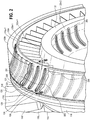
FIG.2 is an enlarged fragmentary isometric view of a plurality of airfoils according toFIGS. 4 or5 disposed between an outer end wall and inner end wall of the gas turbine engine; -
FIG. 3 is an enlarged fragmentary isometric view of a prior art metal strip bonded to an airfoil; -
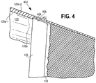
FIG. 4 is a view similar toFIG. 3 with portions broken away of an example embodiment of a sheath coupled to the airfoil and extending through an end wall of the gas turbine engine; -
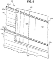
FIG. 5 is an enlarged cross-sectional view of an example embodiment of a sheath coupled to the airfoil and terminating at a surface defining a recess in an end wall of a gas turbine engine; -
FIG. 6 is a sectional view taken generally along the lines 6-6 ofFIG. 2 ; -
FIG. 7 . is an enlarged fragmentary isometric side view of a further example embodiment sheath coupled to the airfoil and extending through an end wall of the gas turbine engine before folding of portions thereof; -
FIG. 8 . is an enlarged fragmentary isometric top view of the example embodiment sheath ofFIG. 7 after folding of the portions thereof; and -
FIG. 9 is an isometric side view of yet another example embodiment sheath. - Referring now to
FIG. 1 , an example embodiment of an aircraft engine in the form of agas turbine engine 100 includes anintake opening 102, afan section 104, acompressor section 106, acombustion chamber 108 that receives compressed air from thecompressor section 106, aturbine section 110 that converts rapidly expanding fuel and air into rotary motive power, and anexhaust 112. Thefan section 104 includes anose cone 114 and plurality offan blades 116. Thecompressor section 106 includes afront bearing housing 118 that includes anouter end wall 120 having aninner portion 120a (with aninner surface 120a-1 and anouter surface 120a-2 not shown inFIG. 1 but shown inFIGs. 2 ,4 ,5 ,6 , and7 ) andouter portion 120b, and aninner end wall 122 having aninner portion 122a (with aninner surface 122a-1 and anouter surface 122a-2 not shown inFIG. 1 but shown inFIGs. 2 ,5 , and6 ) andouter portion 122b. It may be noted that the thickness of theouter end wall 120 and theinner end wall 122 are exaggerated for clarity. In general, the air displaced from theintake opening 102 is directed either to anair bypass 123 or between theouter end wall 120 andinner end wall 122 of thefront bearing housing 118. The displaced air directed to theouter end wall 120 andinner end wall 122 encounters a plurality ofairfoils 124 disposed between theouter portion 120b of theouter end wall 120 and theouter portion 122b of theinner end wall 122. Eachairfoil 124 can be made of a composite material and includes asheath 126 in contact with the leading edge of eachairfoil 124. Thesheath 126 is preferably made of a metallic material or may be made of any other suitable material, such as a composite material. As shown inFIG. 1 , theairfoil 124 may extend through theinner portion 120a of theouter end wall 120 and through theinner portion 122a of theinner end wall 122 and terminate within theend walls airfoil 124 may extend fully through one or both of theend walls - Referring now to
FIG. 2 , an example embodiment airfoil assembly is located behind thefan section 104, and more specifically behind thenose cone 114 and the plurality offan blades 116 in thefront bearing housing 118. As shown inFIG. 2 by the cut-away of theouter portion 120b of theouter end wall 120, eachairfoil 124 has apressure surface 202 and asuction surface 204. Thepressure surface 202 is the surface with a higher static pressure as compared to thesuction surface 204. Thesuction surface 204 is the surface with a lower static pressure as compared to thepressure surface 202. Although both surfaces experience exposure to airflow and are protected by thesheath 126, thepressure surface 202 is generally more exposed to foreign material and/or higher force impacts. Due to the higher exposure, thesheath 126 may extend axially the entire length of thepressure surface 202 or some fraction thereof. The length of thepressure surface 202 refers to the left-to-right dimension as inFIG. 2 whereas the height of theairfoil 124 refers to the distance between theend walls FIGS. 1 ,2 , and4-7 , thesheath 126 may extend the full height or substantially the full height of the associatedairfoil 124 into theend walls pressure surface 202 is preferably at least the length of the sheath on thesuction surface 204. As shown inFIG. 2 andFIG. 6 , illustrated example embodiments also include a plurality ofresilient boots 206 disposed in associated recesses in theend walls sheath 126 andairfoil 124. Theboots 206 hold and position theairfoils 124 in place between theouter end wall 120 andinner end wall 122, dampen vibrations, and allow for some movement of the airfoils if impacted. -
FIG. 3 illustrates a priorart airfoil assembly 300 comprising anairfoil 302 having anend 304 that extends fully through and beyond aportion 306a of anend wall 306, although theend 304 may instead terminate within theend wall 306. Astrip 308 is bonded to the leading edge of theairfoil 302 and does not extend the full length of theairfoil 302, thereby exposing afree edge 310 of thestrip 308 directly to the airflow, which may contain foreign material that can undesirably delaminate thestrip 308 at thefree edge 310 and possibly result in DOD. Additionally, delamination will tend to initiate at the free edge which in the case of prior art resides inside the gas path further increasing both the probability, magnitude, and propagation of a delamination. - Referring now to
FIG. 4 , an exampleembodiment airfoil assembly 400 comprises theinner portion 120a of theouter end wall 120 with surfaces defining arecess 402 between theinner surface 120a-1 andouter surface 120a-2 of theinner portion 120a, wherein anupper end 404 of theairfoil 124 is disposed in therecess 402. Thesheath 126 may be cured in the leading edge of theairfoil 124, or be disposed on the leading edge of the airfoil 124 (not shown). As shown inFIG. 4 , thesheath 126 is cured in the leading edge of theairfoil 124 and extends outwardly at least to a point above theinner surface 120a-1 and up to the surfaces defining therecess 402 so that theedge 406 of thesheath 126 is located outwardly from theinner surface 120a-1 of theinner portion 120a. Curing thesheath 126 into the leading edge and positioning theedge 406 of thesheath 126 in between theinner surface 120a-1 and therecess 402 allows no edge of thesheath 126 to be directly exposed to the airflow between theouter end wall 120 andinner end wall 122, thereby improving the resistance to delamination and/or detachment of thesheath 126 from theairfoil 124. - Referring now to
FIG. 5 , an exampleembodiment airfoil assembly 500 includes anairfoil 124 that extends outwardly at least through theinner portion 120a of theouter end wall 120. Asheath 126 disposed on the leading edge of theairfoil 124 includes afirst edge 502 that also extends at least through theinner portion 120a of theouter end wall 120. In the illustrated embodiment, theairfoil 124 also extends fully through theinner portion 122a of theinner end wall 122 together with asecond edge 504 of thesheath 126. By extending through theinner portion 120a of theouter end wall 120 and theinner portion 122a of theinner end wall 122, thefirst edge 502 and thesecond edge 504 of thesheath 126 are not directly exposed to the airflow between theouter end wall 120 andinner end wall 122, thereby improving the resistance to delamination and/or detachment of thesheath 126 from theairfoil 124. - Referring now to
FIGS. 7 and 8 , an example embodiment airfoilassembly 700 includes anairfoil 124 extending through theinner portion 120a of theouter end wall 120 and thesheath 126 includes anouter end portion 701 that extends outwardly from theairfoil 124 beyond anouter edge 702 of theairfoil 124 through theinner portion 120a of theouter end wall 120. Theportion 701 includes afirst extension member 703 and asecond extension member 704. In an example embodiment (not shown), a portion corresponding to theportion 701 includes extension members, like themembers outer edge 702 of theairfoil 124. Theextension members airfoil 124 are used to further secure thesheath 126 to the leading edge of theairfoil 124. As shownFIG. 8 , the first andsecond extension members end surface 705 of theairfoil 124 and secured to one another using any suitable joining methodology or means so as to radially retain thesheath 126 over the end of theairfoil 124 including but not limited to adhesive bonding, welding, brazing, or a geometric interconnection. While twoextension members sheath 126 over the end of theairfoil 124, further improves the resistance to FOD, DOD, or detachment of thesheath 126 from theairfoil 124. The improvement in resistance may lead to reduced service costs associated with repair and/or replacement of airfoils or airfoil assemblies as well as a reduction in deterioration of the airfoils. Since thesheath 126 may be of metallic or composite material, the improvement in resistance may lead to use of material of less weight, reducing not only cost, but improving the overall engine fuel efficiency. - As shown in
FIG. 9 , an example embodiment of thesheath 126 may be of a single piece of material or segments affixed together to form a single continuous piece of material wherein the one-piece sheath 902 has a complete enclosedfirst end 904 and complete enclosedsecond end 906. Complete enclosure of both ends of the one-piece sheath 902 and capture of portions thereof by one or both of theend walls sheath 902 on the leading edge of anairfoil 124. - In summary, the sheath disposed around the leading edge of an airfoil disposed within a surface defining a recess in at least one end wall or wherein the sheath extends outwardly from a first portion of an airfoil through at least one end wall has numerous advantages. Moreover, the use of additional retainment using at least one extension member to radially retain the sheath over an airfoil improves the resistance of the sheath to detach from the airfoil from FOD, DOD, or erosion. Moreover, improved resistance to FOD, DOD, erosion, and detachment will reduce service costs associated to replacing airfoils or airfoil assemblies. Moreover, the improved resistance may lead to the use of more composite materials in gas turbine engines, allowing for a reduction in overall weight, cost to manufacture, and with the reduction in weight may improve overall fuel efficiency.
- The use of the terms "a" and "an" and "the" and similar references in the context of describing the invention (especially in the context of the following claims) are to be construed to cover both the singular and the plural, unless otherwise indicated herein or clearly contradicted by context. Recitation of ranges of values herein are merely intended to serve as a shorthand method of referring individually to each separate value falling within the range, unless otherwise indicated herein, and each separate value is incorporated into the specification as if it were individually recited herein. All methods described herein can be performed in any suitable order unless otherwise indicated herein or otherwise clearly contradicted by context. The use of any and all examples, or exemplary language (e.g., "such as") provided herein, is intended merely to better illuminate the disclosure and does not pose a limitation on the scope of the disclosure unless otherwise claimed. No language in the specification should be construed as indicating any non-claimed element as essential to the practice of the disclosure.
- Numerous modifications to the present disclosure will be apparent to those skilled in the art in view of the foregoing description. It should be understood that the illustrated embodiments are exemplary only, and should not be taken as limiting the scope of the disclosure.
Claims (10)
- An airfoil assembly for a gas turbine engine (100), comprising:a first end wall (120) with surfaces (120a-1, 120a-2) defining a first recess;a second end wall (122) with surfaces (122a-1, 122a-2) defining a second recess;an airfoil (124) having a first portion disposed in the first recess, a second portion disposed in the second recess, and a leading edge disposed between the first and second portions; anda sheath (126) in contact with the first and second portions of the airfoil and covering the leading edge of the airfoil (124) between the surfaces (120a-1, 120a-2; 122a-1, 122a-2) defining the first and second recesses.
- An airfoil assembly for a gas turbine engine according to claim 1, wherein the sheath (126) extends outwardly from the first portion of the airfoil (124) through the first end wall (120) and from the second portion of the airfoil (124) through the second end wall (122).
- An airfoil assembly for a gas turbine engine according to claim 1, wherein the sheath (126) has at least one extension member (703) at one end and at least one extension member (704) at another end wherein the at least one extension member (703) at one end is joined to at least one extension member (704) at another end.
- An airfoil assembly for a gas turbine engine according to claim 3, wherein the sheath (126) is radially retained over the end (705) of the airfoil.
- An airfoil assembly for a gas turbine according to claim 1, wherein the sheath (126) fully encloses at least one of the ends of the airfoil (124).
- An airfoil assembly for a gas turbine according to claim 1, wherein the sheath (126) is disposed in the leading edge.
- An airfoil assembly for a gas turbine according to claim 6, wherein the sheath (126) is cured in the leading edge.
- An airfoil assembly for a gas turbine according to claim 1, wherein the airfoil (124) has a pressure surface (202) and a suction surface (204).
- An airfoil assembly for a gas turbine according to claim 8, wherein the sheath (126) axially extends at most the length of the pressure surface (202).
- An airfoil assembly for a gas turbine according to claim 9, wherein the length of the sheath (126) on the pressure surface (202) is at least the length of the sheath (126) on the suction surface (204).
Applications Claiming Priority (1)
| Application Number | Priority Date | Filing Date | Title |
|---|---|---|---|
| US15/651,156 US10612386B2 (en) | 2017-07-17 | 2017-07-17 | Apparatus for airfoil leading edge protection |
Publications (2)
| Publication Number | Publication Date |
|---|---|
| EP3431709A1 true EP3431709A1 (en) | 2019-01-23 |
| EP3431709B1 EP3431709B1 (en) | 2020-04-08 |
Family
ID=62712833
Family Applications (1)
| Application Number | Title | Priority Date | Filing Date |
|---|---|---|---|
| EP18178435.6A Active EP3431709B1 (en) | 2017-07-17 | 2018-06-19 | Apparatus for airfoil leading edge protection |
Country Status (3)
| Country | Link |
|---|---|
| US (1) | US10612386B2 (en) |
| EP (1) | EP3431709B1 (en) |
| CA (1) | CA2984853A1 (en) |
Families Citing this family (1)
| Publication number | Priority date | Publication date | Assignee | Title |
|---|---|---|---|---|
| US11725525B2 (en) * | 2022-01-19 | 2023-08-15 | Rolls-Royce North American Technologies Inc. | Engine section stator vane assembly with band stiffness features for turbine engines |
Citations (3)
| Publication number | Priority date | Publication date | Assignee | Title |
|---|---|---|---|---|
| US3836282A (en) * | 1973-03-28 | 1974-09-17 | United Aircraft Corp | Stator vane support and construction thereof |
| WO2015006488A1 (en) * | 2013-07-09 | 2015-01-15 | United Technologies Corporation | Plating a composite to enhance bonding of metallic components |
| EP3018363A1 (en) * | 2013-07-02 | 2016-05-11 | IHI Corporation | Stator vane structure and turbofan jet engine using same |
Family Cites Families (17)
| Publication number | Priority date | Publication date | Assignee | Title |
|---|---|---|---|---|
| US4006999A (en) | 1975-07-17 | 1977-02-08 | The United States Of America As Represented By The Administrator Of The National Aeronautics And Space Administration | Leading edge protection for composite blades |
| US5449273A (en) | 1994-03-21 | 1995-09-12 | United Technologies Corporation | Composite airfoil leading edge protection |
| FR2884550B1 (en) * | 2005-04-15 | 2010-09-17 | Snecma Moteurs | PIECE FOR PROTECTING THE EDGE OF A BLADE |
| US7789621B2 (en) * | 2005-06-27 | 2010-09-07 | Rolls-Royce North American Technologies, Inc. | Gas turbine engine airfoil |
| US8088498B2 (en) | 2007-05-23 | 2012-01-03 | Hamilton Sundstrand Corporation | Electro-formed sheath for use on airfoil components |
| US7736130B2 (en) | 2007-07-23 | 2010-06-15 | General Electric Company | Airfoil and method for protecting airfoil leading edge |
| US20100008788A1 (en) | 2008-07-14 | 2010-01-14 | Barbee Brent W | Protector for a leading edge of an airfoil |
| US8556589B2 (en) * | 2009-06-24 | 2013-10-15 | Teledyne Scientific & Imaging, Llc | Hybrid composite for erosion resistant helicopter blades |
| GB0916758D0 (en) * | 2009-09-24 | 2009-11-04 | Rolls Royce Plc | A hybrid component |
| US20120021243A1 (en) | 2010-07-23 | 2012-01-26 | General Electric Company | Components with bonded edges |
| US8550776B2 (en) * | 2010-07-28 | 2013-10-08 | General Electric Company | Composite vane mounting |
| US9556742B2 (en) * | 2010-11-29 | 2017-01-31 | United Technologies Corporation | Composite airfoil and turbine engine |
| US20140064937A1 (en) * | 2012-06-29 | 2014-03-06 | General Electric Company | Fan blade brush tip |
| WO2014081355A1 (en) * | 2012-11-20 | 2014-05-30 | Saab Ab | An erosion protection strip for a leading edge of an airfoil article |
| GB201402022D0 (en) | 2014-02-06 | 2014-03-26 | Rolls Royce Plc | Leading edge protector |
| WO2015160527A1 (en) | 2014-04-17 | 2015-10-22 | General Electric Company | Method for manufacturing leading edge guard |
| EP3248867B1 (en) * | 2016-05-23 | 2019-09-11 | Ratier-Figeac SAS | Propeller blade sheath |
-
2017
- 2017-07-17 US US15/651,156 patent/US10612386B2/en active Active
- 2017-11-07 CA CA2984853A patent/CA2984853A1/en not_active Abandoned
-
2018
- 2018-06-19 EP EP18178435.6A patent/EP3431709B1/en active Active
Patent Citations (3)
| Publication number | Priority date | Publication date | Assignee | Title |
|---|---|---|---|---|
| US3836282A (en) * | 1973-03-28 | 1974-09-17 | United Aircraft Corp | Stator vane support and construction thereof |
| EP3018363A1 (en) * | 2013-07-02 | 2016-05-11 | IHI Corporation | Stator vane structure and turbofan jet engine using same |
| WO2015006488A1 (en) * | 2013-07-09 | 2015-01-15 | United Technologies Corporation | Plating a composite to enhance bonding of metallic components |
Also Published As
| Publication number | Publication date |
|---|---|
| EP3431709B1 (en) | 2020-04-08 |
| US10612386B2 (en) | 2020-04-07 |
| CA2984853A1 (en) | 2019-01-17 |
| US20190017387A1 (en) | 2019-01-17 |
Similar Documents
| Publication | Publication Date | Title |
|---|---|---|
| CA2614406C (en) | Methods and apparatus for fabricating a fan assembly for use with turbine engines | |
| EP2767676B1 (en) | Fan containment system, corresponding fan assembly and gas turbine engine | |
| CN102312682B (en) | Composite turbomachine blade and the turbomachine rotor assembly comprising this blade | |
| US8376712B2 (en) | Fan airfoil sheath | |
| EP2775103B1 (en) | CMC turbine engine component | |
| US10815798B2 (en) | Turbine engine blade with leading edge strip | |
| EP3473811B1 (en) | Fan blade platform | |
| EP1245791A2 (en) | A gas turbine engine blade containment assembly | |
| EP1911931A2 (en) | Fan exit guide vane and method of repairing therof | |
| CN110685957A (en) | blade containment structure | |
| CN110131210A (en) | Turbogenerator with composite blading | |
| EP2096269A2 (en) | Fan track liner assembly for a gas turbine engine | |
| EP1924758B1 (en) | Vane assembly with outer grommets | |
| US10883374B2 (en) | Blade comprising a folded leading edge shield and method of manufacturing the blade | |
| EP1584797A2 (en) | A containment apparatus for a gas turbine engine | |
| CN111197596A (en) | Composite fan blades with abrasive tips | |
| EP3001040A1 (en) | Gas turbine engine | |
| JP6631822B2 (en) | Fan blade | |
| US20160312793A1 (en) | Electrostatic Discharge Prevention for a Fan Blade | |
| EP3187695A1 (en) | A wrap comprising sheets of graphene for a casing of a rotating member, corresponding turbofan engine and method of asssaembling a turbofan engine | |
| US10612386B2 (en) | Apparatus for airfoil leading edge protection | |
| RU2606524C2 (en) | Assembly formed by gas turbine engine and system for its attachment to aircraft structure | |
| EP2955326B1 (en) | Gas turbine airfoil with a grounding element | |
| EP2930306B1 (en) | Gas turbine engine fan with discrete platforms for electrically grounding sheaths of fan airfoils |
Legal Events
| Date | Code | Title | Description |
|---|---|---|---|
| PUAI | Public reference made under article 153(3) epc to a published international application that has entered the european phase |
Free format text: ORIGINAL CODE: 0009012 |
|
| STAA | Information on the status of an ep patent application or granted ep patent |
Free format text: STATUS: THE APPLICATION HAS BEEN PUBLISHED |
|
| AK | Designated contracting states |
Kind code of ref document: A1 Designated state(s): AL AT BE BG CH CY CZ DE DK EE ES FI FR GB GR HR HU IE IS IT LI LT LU LV MC MK MT NL NO PL PT RO RS SE SI SK SM TR |
|
| AX | Request for extension of the european patent |
Extension state: BA ME |
|
| STAA | Information on the status of an ep patent application or granted ep patent |
Free format text: STATUS: REQUEST FOR EXAMINATION WAS MADE |
|
| 17P | Request for examination filed |
Effective date: 20190612 |
|
| RBV | Designated contracting states (corrected) |
Designated state(s): AL AT BE BG CH CY CZ DE DK EE ES FI FR GB GR HR HU IE IS IT LI LT LU LV MC MK MT NL NO PL PT RO RS SE SI SK SM TR |
|
| RIC1 | Information provided on ipc code assigned before grant |
Ipc: F01D 9/04 20060101ALI20191009BHEP Ipc: F01D 5/14 20060101AFI20191009BHEP |
|
| GRAP | Despatch of communication of intention to grant a patent |
Free format text: ORIGINAL CODE: EPIDOSNIGR1 |
|
| STAA | Information on the status of an ep patent application or granted ep patent |
Free format text: STATUS: GRANT OF PATENT IS INTENDED |
|
| INTG | Intention to grant announced |
Effective date: 20191119 |
|
| GRAS | Grant fee paid |
Free format text: ORIGINAL CODE: EPIDOSNIGR3 |
|
| GRAJ | Information related to disapproval of communication of intention to grant by the applicant or resumption of examination proceedings by the epo deleted |
Free format text: ORIGINAL CODE: EPIDOSDIGR1 |
|
| GRAL | Information related to payment of fee for publishing/printing deleted |
Free format text: ORIGINAL CODE: EPIDOSDIGR3 |
|
| STAA | Information on the status of an ep patent application or granted ep patent |
Free format text: STATUS: REQUEST FOR EXAMINATION WAS MADE |
|
| GRAR | Information related to intention to grant a patent recorded |
Free format text: ORIGINAL CODE: EPIDOSNIGR71 |
|
| STAA | Information on the status of an ep patent application or granted ep patent |
Free format text: STATUS: GRANT OF PATENT IS INTENDED |
|
| GRAA | (expected) grant |
Free format text: ORIGINAL CODE: 0009210 |
|
| STAA | Information on the status of an ep patent application or granted ep patent |
Free format text: STATUS: THE PATENT HAS BEEN GRANTED |
|
| INTC | Intention to grant announced (deleted) | ||
| INTG | Intention to grant announced |
Effective date: 20200227 |
|
| AK | Designated contracting states |
Kind code of ref document: B1 Designated state(s): AL AT BE BG CH CY CZ DE DK EE ES FI FR GB GR HR HU IE IS IT LI LT LU LV MC MK MT NL NO PL PT RO RS SE SI SK SM TR |
|
| REG | Reference to a national code |
Ref country code: CH Ref legal event code: EP Ref country code: AT Ref legal event code: REF Ref document number: 1254641 Country of ref document: AT Kind code of ref document: T Effective date: 20200415 |
|
| REG | Reference to a national code |
Ref country code: DE Ref legal event code: R096 Ref document number: 602018003558 Country of ref document: DE |
|
| REG | Reference to a national code |
Ref country code: IE Ref legal event code: FG4D |
|
| REG | Reference to a national code |
Ref country code: NL Ref legal event code: MP Effective date: 20200408 |
|
| REG | Reference to a national code |
Ref country code: LT Ref legal event code: MG4D |
|
| PG25 | Lapsed in a contracting state [announced via postgrant information from national office to epo] |
Ref country code: GR Free format text: LAPSE BECAUSE OF FAILURE TO SUBMIT A TRANSLATION OF THE DESCRIPTION OR TO PAY THE FEE WITHIN THE PRESCRIBED TIME-LIMIT Effective date: 20200709 Ref country code: LT Free format text: LAPSE BECAUSE OF FAILURE TO SUBMIT A TRANSLATION OF THE DESCRIPTION OR TO PAY THE FEE WITHIN THE PRESCRIBED TIME-LIMIT Effective date: 20200408 Ref country code: PT Free format text: LAPSE BECAUSE OF FAILURE TO SUBMIT A TRANSLATION OF THE DESCRIPTION OR TO PAY THE FEE WITHIN THE PRESCRIBED TIME-LIMIT Effective date: 20200817 Ref country code: SE Free format text: LAPSE BECAUSE OF FAILURE TO SUBMIT A TRANSLATION OF THE DESCRIPTION OR TO PAY THE FEE WITHIN THE PRESCRIBED TIME-LIMIT Effective date: 20200408 Ref country code: FI Free format text: LAPSE BECAUSE OF FAILURE TO SUBMIT A TRANSLATION OF THE DESCRIPTION OR TO PAY THE FEE WITHIN THE PRESCRIBED TIME-LIMIT Effective date: 20200408 Ref country code: NO Free format text: LAPSE BECAUSE OF FAILURE TO SUBMIT A TRANSLATION OF THE DESCRIPTION OR TO PAY THE FEE WITHIN THE PRESCRIBED TIME-LIMIT Effective date: 20200708 Ref country code: IS Free format text: LAPSE BECAUSE OF FAILURE TO SUBMIT A TRANSLATION OF THE DESCRIPTION OR TO PAY THE FEE WITHIN THE PRESCRIBED TIME-LIMIT Effective date: 20200808 Ref country code: NL Free format text: LAPSE BECAUSE OF FAILURE TO SUBMIT A TRANSLATION OF THE DESCRIPTION OR TO PAY THE FEE WITHIN THE PRESCRIBED TIME-LIMIT Effective date: 20200408 |
|
| REG | Reference to a national code |
Ref country code: AT Ref legal event code: MK05 Ref document number: 1254641 Country of ref document: AT Kind code of ref document: T Effective date: 20200408 |
|
| PG25 | Lapsed in a contracting state [announced via postgrant information from national office to epo] |
Ref country code: RS Free format text: LAPSE BECAUSE OF FAILURE TO SUBMIT A TRANSLATION OF THE DESCRIPTION OR TO PAY THE FEE WITHIN THE PRESCRIBED TIME-LIMIT Effective date: 20200408 Ref country code: HR Free format text: LAPSE BECAUSE OF FAILURE TO SUBMIT A TRANSLATION OF THE DESCRIPTION OR TO PAY THE FEE WITHIN THE PRESCRIBED TIME-LIMIT Effective date: 20200408 Ref country code: BG Free format text: LAPSE BECAUSE OF FAILURE TO SUBMIT A TRANSLATION OF THE DESCRIPTION OR TO PAY THE FEE WITHIN THE PRESCRIBED TIME-LIMIT Effective date: 20200708 Ref country code: LV Free format text: LAPSE BECAUSE OF FAILURE TO SUBMIT A TRANSLATION OF THE DESCRIPTION OR TO PAY THE FEE WITHIN THE PRESCRIBED TIME-LIMIT Effective date: 20200408 |
|
| PG25 | Lapsed in a contracting state [announced via postgrant information from national office to epo] |
Ref country code: AL Free format text: LAPSE BECAUSE OF FAILURE TO SUBMIT A TRANSLATION OF THE DESCRIPTION OR TO PAY THE FEE WITHIN THE PRESCRIBED TIME-LIMIT Effective date: 20200408 |
|
| REG | Reference to a national code |
Ref country code: DE Ref legal event code: R119 Ref document number: 602018003558 Country of ref document: DE |
|
| PG25 | Lapsed in a contracting state [announced via postgrant information from national office to epo] |
Ref country code: MC Free format text: LAPSE BECAUSE OF FAILURE TO SUBMIT A TRANSLATION OF THE DESCRIPTION OR TO PAY THE FEE WITHIN THE PRESCRIBED TIME-LIMIT Effective date: 20200408 Ref country code: IT Free format text: LAPSE BECAUSE OF FAILURE TO SUBMIT A TRANSLATION OF THE DESCRIPTION OR TO PAY THE FEE WITHIN THE PRESCRIBED TIME-LIMIT Effective date: 20200408 Ref country code: DK Free format text: LAPSE BECAUSE OF FAILURE TO SUBMIT A TRANSLATION OF THE DESCRIPTION OR TO PAY THE FEE WITHIN THE PRESCRIBED TIME-LIMIT Effective date: 20200408 Ref country code: SM Free format text: LAPSE BECAUSE OF FAILURE TO SUBMIT A TRANSLATION OF THE DESCRIPTION OR TO PAY THE FEE WITHIN THE PRESCRIBED TIME-LIMIT Effective date: 20200408 Ref country code: AT Free format text: LAPSE BECAUSE OF FAILURE TO SUBMIT A TRANSLATION OF THE DESCRIPTION OR TO PAY THE FEE WITHIN THE PRESCRIBED TIME-LIMIT Effective date: 20200408 Ref country code: EE Free format text: LAPSE BECAUSE OF FAILURE TO SUBMIT A TRANSLATION OF THE DESCRIPTION OR TO PAY THE FEE WITHIN THE PRESCRIBED TIME-LIMIT Effective date: 20200408 Ref country code: RO Free format text: LAPSE BECAUSE OF FAILURE TO SUBMIT A TRANSLATION OF THE DESCRIPTION OR TO PAY THE FEE WITHIN THE PRESCRIBED TIME-LIMIT Effective date: 20200408 Ref country code: ES Free format text: LAPSE BECAUSE OF FAILURE TO SUBMIT A TRANSLATION OF THE DESCRIPTION OR TO PAY THE FEE WITHIN THE PRESCRIBED TIME-LIMIT Effective date: 20200408 Ref country code: CZ Free format text: LAPSE BECAUSE OF FAILURE TO SUBMIT A TRANSLATION OF THE DESCRIPTION OR TO PAY THE FEE WITHIN THE PRESCRIBED TIME-LIMIT Effective date: 20200408 |
|
| PLBE | No opposition filed within time limit |
Free format text: ORIGINAL CODE: 0009261 |
|
| STAA | Information on the status of an ep patent application or granted ep patent |
Free format text: STATUS: NO OPPOSITION FILED WITHIN TIME LIMIT |
|
| PG25 | Lapsed in a contracting state [announced via postgrant information from national office to epo] |
Ref country code: PL Free format text: LAPSE BECAUSE OF FAILURE TO SUBMIT A TRANSLATION OF THE DESCRIPTION OR TO PAY THE FEE WITHIN THE PRESCRIBED TIME-LIMIT Effective date: 20200408 Ref country code: SK Free format text: LAPSE BECAUSE OF FAILURE TO SUBMIT A TRANSLATION OF THE DESCRIPTION OR TO PAY THE FEE WITHIN THE PRESCRIBED TIME-LIMIT Effective date: 20200408 |
|
| 26N | No opposition filed |
Effective date: 20210112 |
|
| PG25 | Lapsed in a contracting state [announced via postgrant information from national office to epo] |
Ref country code: LU Free format text: LAPSE BECAUSE OF NON-PAYMENT OF DUE FEES Effective date: 20200619 |
|
| REG | Reference to a national code |
Ref country code: BE Ref legal event code: MM Effective date: 20200630 |
|
| PG25 | Lapsed in a contracting state [announced via postgrant information from national office to epo] |
Ref country code: IE Free format text: LAPSE BECAUSE OF NON-PAYMENT OF DUE FEES Effective date: 20200619 |
|
| PG25 | Lapsed in a contracting state [announced via postgrant information from national office to epo] |
Ref country code: BE Free format text: LAPSE BECAUSE OF NON-PAYMENT OF DUE FEES Effective date: 20200630 Ref country code: DE Free format text: LAPSE BECAUSE OF NON-PAYMENT OF DUE FEES Effective date: 20210101 Ref country code: SI Free format text: LAPSE BECAUSE OF FAILURE TO SUBMIT A TRANSLATION OF THE DESCRIPTION OR TO PAY THE FEE WITHIN THE PRESCRIBED TIME-LIMIT Effective date: 20200408 |
|
| REG | Reference to a national code |
Ref country code: CH Ref legal event code: PL |
|
| PG25 | Lapsed in a contracting state [announced via postgrant information from national office to epo] |
Ref country code: LI Free format text: LAPSE BECAUSE OF NON-PAYMENT OF DUE FEES Effective date: 20210630 Ref country code: CH Free format text: LAPSE BECAUSE OF NON-PAYMENT OF DUE FEES Effective date: 20210630 |
|
| PG25 | Lapsed in a contracting state [announced via postgrant information from national office to epo] |
Ref country code: TR Free format text: LAPSE BECAUSE OF FAILURE TO SUBMIT A TRANSLATION OF THE DESCRIPTION OR TO PAY THE FEE WITHIN THE PRESCRIBED TIME-LIMIT Effective date: 20200408 Ref country code: MT Free format text: LAPSE BECAUSE OF FAILURE TO SUBMIT A TRANSLATION OF THE DESCRIPTION OR TO PAY THE FEE WITHIN THE PRESCRIBED TIME-LIMIT Effective date: 20200408 Ref country code: CY Free format text: LAPSE BECAUSE OF FAILURE TO SUBMIT A TRANSLATION OF THE DESCRIPTION OR TO PAY THE FEE WITHIN THE PRESCRIBED TIME-LIMIT Effective date: 20200408 |
|
| PG25 | Lapsed in a contracting state [announced via postgrant information from national office to epo] |
Ref country code: MK Free format text: LAPSE BECAUSE OF FAILURE TO SUBMIT A TRANSLATION OF THE DESCRIPTION OR TO PAY THE FEE WITHIN THE PRESCRIBED TIME-LIMIT Effective date: 20200408 |
|
| GBPC | Gb: european patent ceased through non-payment of renewal fee |
Effective date: 20220619 |
|
| PG25 | Lapsed in a contracting state [announced via postgrant information from national office to epo] |
Ref country code: GB Free format text: LAPSE BECAUSE OF NON-PAYMENT OF DUE FEES Effective date: 20220619 |
|
| P01 | Opt-out of the competence of the unified patent court (upc) registered |
Effective date: 20230528 |
|
| PGFP | Annual fee paid to national office [announced via postgrant information from national office to epo] |
Ref country code: FR Payment date: 20250624 Year of fee payment: 8 |