EP3431398A1 - Satellite cover panel - Google Patents
Satellite cover panel Download PDFInfo
- Publication number
- EP3431398A1 EP3431398A1 EP17182497.2A EP17182497A EP3431398A1 EP 3431398 A1 EP3431398 A1 EP 3431398A1 EP 17182497 A EP17182497 A EP 17182497A EP 3431398 A1 EP3431398 A1 EP 3431398A1
- Authority
- EP
- European Patent Office
- Prior art keywords
- satellite
- cover panel
- satellite cover
- logic board
- payload
- Prior art date
- Legal status (The legal status is an assumption and is not a legal conclusion. Google has not performed a legal analysis and makes no representation as to the accuracy of the status listed.)
- Granted
Links
Images


Classifications
-
- B—PERFORMING OPERATIONS; TRANSPORTING
- B64—AIRCRAFT; AVIATION; COSMONAUTICS
- B64G—COSMONAUTICS; VEHICLES OR EQUIPMENT THEREFOR
- B64G1/00—Cosmonautic vehicles
- B64G1/22—Parts of, or equipment specially adapted for fitting in or to, cosmonautic vehicles
- B64G1/42—Arrangements or adaptations of power supply systems
- B64G1/44—Arrangements or adaptations of power supply systems using radiation, e.g. deployable solar arrays
-
- B—PERFORMING OPERATIONS; TRANSPORTING
- B64—AIRCRAFT; AVIATION; COSMONAUTICS
- B64G—COSMONAUTICS; VEHICLES OR EQUIPMENT THEREFOR
- B64G1/00—Cosmonautic vehicles
- B64G1/22—Parts of, or equipment specially adapted for fitting in or to, cosmonautic vehicles
- B64G1/42—Arrangements or adaptations of power supply systems
- B64G1/425—Power storage
-
- B—PERFORMING OPERATIONS; TRANSPORTING
- B64—AIRCRAFT; AVIATION; COSMONAUTICS
- B64G—COSMONAUTICS; VEHICLES OR EQUIPMENT THEREFOR
- B64G1/00—Cosmonautic vehicles
- B64G1/10—Artificial satellites; Systems of such satellites; Interplanetary vehicles
-
- B—PERFORMING OPERATIONS; TRANSPORTING
- B64—AIRCRAFT; AVIATION; COSMONAUTICS
- B64G—COSMONAUTICS; VEHICLES OR EQUIPMENT THEREFOR
- B64G1/00—Cosmonautic vehicles
- B64G1/22—Parts of, or equipment specially adapted for fitting in or to, cosmonautic vehicles
- B64G1/222—Parts of, or equipment specially adapted for fitting in or to, cosmonautic vehicles for deploying structures between a stowed and deployed state
- B64G1/2221—Parts of, or equipment specially adapted for fitting in or to, cosmonautic vehicles for deploying structures between a stowed and deployed state characterised by the manner of deployment
- B64G1/2222—Folding
-
- B—PERFORMING OPERATIONS; TRANSPORTING
- B64—AIRCRAFT; AVIATION; COSMONAUTICS
- B64G—COSMONAUTICS; VEHICLES OR EQUIPMENT THEREFOR
- B64G1/00—Cosmonautic vehicles
- B64G1/22—Parts of, or equipment specially adapted for fitting in or to, cosmonautic vehicles
- B64G1/223—Modular spacecraft systems
-
- B—PERFORMING OPERATIONS; TRANSPORTING
- B64—AIRCRAFT; AVIATION; COSMONAUTICS
- B64G—COSMONAUTICS; VEHICLES OR EQUIPMENT THEREFOR
- B64G1/00—Cosmonautic vehicles
- B64G1/22—Parts of, or equipment specially adapted for fitting in or to, cosmonautic vehicles
- B64G1/42—Arrangements or adaptations of power supply systems
- B64G1/44—Arrangements or adaptations of power supply systems using radiation, e.g. deployable solar arrays
- B64G1/443—Photovoltaic cell arrays
Definitions
- the invention regards a satellite cover panel. Further, the invention regards a satellite comprising at least one satellite cover panel.
- the satellite cover panel allows covering a satellite, particularly a payload bay of a satellite.
- satellites which comprise several subsystems.
- the subsystems are connected according to a satellite bus via cable harness and/or plug connection.
- Such subsystems particularly comprise an energy supply subsystem, a main control subsystem, an attitude control subsystem, and a communication subsystem.
- An object of the invention is to provide a satellite cover panel, which is simple to manufacture, which protects the payload, which provides major/some/all features of a satellite bus and which allows increasing the payload volume.
- a satellite cover panel for covering a satellite, particularly a payload bay of a satellite comprising an energy storage module, at least one energy generating module, preferably at least one solar cell, and a logic board.
- the energy generating module defines, at least partially, a first outer surface of the satellite cover panel.
- the logic board on the other side defines, at least partially, a second outer surface of the satellite cover panel.
- the first outer surface and the second outer surface face away from each other and from the energy storage module. Therefore, the energy generating module and the logic board each are provided on an outer side of the satellite cover panel, while the energy storage module is provided in between the energy generating module and the logic board.
- the energy storage module allows radiation protection of the interior space of the satellite, particularly of the payload bay covered by the satellite cover panel.
- the energy storage module holds the at least one energy generating module and the logic board. This leads to a stiff and solid design of the satellite cover panel.
- the satellite cover panel therefore helps to reinforce the design of a satellite provided with the satellite cover panel.
- the first outer surface and the second outer surface cover the same area or differ in area of at most 20%, preferably at most 10%.
- the energy storage module preferably does not extend over the edges of the first outer surface or the second outer surface. In this way, a panel is provided which can be used as any ordinary cover panel.
- the satellite cover panel includes functionality which at least partially can replace the subsystems provided in an ordinary satellite. Therefore, the payload volume is increased since less or no conventional subsystems are required when adopting the satellite cover panels according to the present invention.
- the dimensions of the first outer surface and the second outer surface are larger than a thickness measured between the first outer surface and the second outer surface.
- the first outer surface and the second outer surface therefore are the largest surfaces of the satellite cover panel.
- the satellite cover panel can have the same dimensions than any ordinary cover panel.
- the satellite cover panel can have a minimum size of 5 cm x 5 cm, wherein the thickness is less than 20%, preferably less than 10% of the side length.
- the energy generating module comprises one or two or more solar cells, wherein each solar cell may have a dimension of 4 cm x 8 cm with a thickness smaller than 1 mm. Those dimensions are common for satellites, such that particularly standard solar cells can be adopted for the satellite cover panel.
- the energy storage module preferably is a battery, particularly a structurally integrated battery. Due to the battery's layer composition, an improved radiation protection is established. Therefore, the satellite cover panel can efficiently cover a payload and/or other sections of interior space of the satellite and protect the payload and/or other sections of interior space of the satellite from radiation.
- the battery preferably has a flat shape such that the satellite cover panel also has a flat shape. Particularly by using structurally integrated batteries, the satellite cover panel can have a flat design while at the same time being built in a solid way.
- the satellite cover panel may comprise at least one further radiation shield layer, which might be provided between the at least one energy generating module and the energy storage module and/or between the energy storage module and the logic board.
- the energy storage module may comprise one, two or more energy storage devices, particularly one, two or more batteries.
- the logic board preferably comprises at least one sensor for detecting an orientation of at least one axis of the satellite cover panel.
- the sensor allows attitude determination to realize attitude control of the whole satellite regarding at least one axis of the satellite.
- attitude control data of sensors of logic boards from at least two different satellite cover panels might be combined.
- the sensor preferably allows self-configuration after the satellite cover panel is provided to the satellite. In case more than one satellite cover panel are provided, redundancy is increased since each sensor can independently detect an orientation of the satellite cover panel and therefore of the satellite.
- the logic board preferably comprises an attitude control system for controlling an orientation of the satellite cover panel.
- an attitude control system for controlling an orientation of the satellite cover panel.
- redundancy and simultaneously controllable axis number can be increased by providing more than one satellite cover panels.
- the attitude control system includes a magnetic field based actuator system.
- the logic board comprises a microprocessor.
- the microprocessor is a main control unit which allows controlling the functionality of the satellite equipped with the satellite cover panel and/or a payload of the satellite.
- the redundancy can be increased by providing more than one satellite cover panel.
- performance of the microprocessor can be increased by combining several microprocessors of the satellite cover panels.
- the logic board particularly comprises a connecting element.
- the connecting element is adapted to connect the logic board to another logic board and/or to a payload provided in the payload bay. Therefore, the satellite bus according to the prior art definition is completely provided in the cover panels of the satellite. This increases the volume of the payload such that the satellite is more efficient.
- the satellite cover panel favorably is symmetrical with respect to a center axis perpendicular to the satellite cover panel. Said center axis particularly extends perpendicular to the first outer surface and the second outer surface.
- the satellite cover panel comprises at least one connection means on at least one outer side, preferably on each outer side for connecting the logic board and/or the energy storage module to a logic board and/or to an energy storage module of another/other satellite cover panel(s) and/or to a payload provided in the payload bay.
- the satellite cover panel preferably comprises a holding element having a first portion and a second portion connected via a hinge.
- the first portion may hold the at least one energy generating module, which defines, at least partially, the first outer surface.
- the second portion may hold at least one additional energy generating module.
- the at least one energy generating module defining, at least partially, the first surface is covered by the second portion of the holding element.
- the surface for providing energy generating modules is increased, such that an increased generation of energy is possible.
- the invention further regards a satellite comprising a frame.
- the satellite comprises at least one satellite cover panel as described above.
- the at least one satellite cover panel is mounted to the frame to set up an outer surface of the satellite. Therefore, the frame preferably is covered by the satellite cover panels.
- the satellite cover panels particularly are the only elements visible from outside the satellite.
- the satellite comprises at least two, more preferably at least three and most preferably at least four satellite cover panels as described above.
- the first outer surface of each satellite cover panel faces away from the frame.
- the second outer surface of each satellite over panel faces towards the frame.
- the first outer surface comprises the at least one energy generating module, preferably the at least one solar cell. This energy generating module therefore allows providing the satellite with energy.
- the energy is stored within the energy storage module of each satellite cover panel and can be supplied to the payload and/or to the logic board of the satellite cover panel.
- the logic boards of at least some of all satellite cover panels are interconnected. Therefore, the satellite cover panels are electrically coupled. This allows exchanging data between the logic boards of the satellite cover panels.
- the interconnection allows increased redundancy on the one hand and/or increased performance on the other hand. Therefore, the satellite comprising the satellite cover panels according to the invention can be set up in a very flexible and scalable way. It is possible to increase redundancy by controlling the microprocessors and/or sensors and/or attitude control systems individually. In this case, damage or failure of one of these components does not lead to failure of the whole satellite.
- several microprocessors can be combined to increase the calculation performance. This allows employing rather cheap hardware with low performance, since the combination of the microprocessors leads to increased performance.
- the satellite cover panels preferably all the time ensure at least partial radiation protection and cover of the payload.
- the energy storage modules of at least some of all satellite cover panels may be interconnected.
- the interconnection allows increased redundancy on the one hand and/or increased energy storage capacity on the other hand.
- the satellite cover panels Independent from the energy storage module or the whole satellite cover panel being active or inactive, the satellite cover panels all the time ensure radiation protection and cover of the payload.
- the satellite cover panels are fixed to each other to stiffen the frame. Therefore, the satellite cover panels may be mechanically coupled.
- the frame itself does not have to bear the entire load generated by the payload. Therefore, the satellite is very solid and insensitive against mechanical influences.
- the radiation protection provided by the satellite cover panel and/or the increased redundancy allows employing logic bards that include components which are not specifically designed for use in space. This simplifies manufacturing of the logic boards and of the satellite cover panels and reduces the manufacturing costs.
- the frame preferably defines a payload bay, in which a payload can be provided.
- the at least one satellite cover panel is mounted to the frame to cover the payload bay.
- the payload bay is at least partially covered by satellite cover panels as described above.
- the payload bay might require an opening to allow receiving data from outside. This might be the case if the payload is a camera; the lens system should not be covered or concealed by the satellite cover panel. Such an opening can be established by not providing a satellite cover panel to a respective portion of the frame.
- the first outer surface of each satellite cover panel faces away from the payload bay.
- the second outer surface of each satellite over panel faces towards the payload bay. Therefore, the first outer surface, which includes the at least one energy generating module, preferably the at least one solar cell, is arranged to face an outside of the satellite. This allows the energy generating module(s) generating energy from luminous energy.
- the satellite may also comprise cover panels other than the above described cover panels. In this case, these cover panels may not provide any further function. There might be cover panels provided for radiation protection only. That means, the satellite can comprise ordinary cover panels according to the prior art. Preferably, the different cover panels can all be exchanged with each other. Particularly, the above described satellite cover panel can be exchanged with any ordinary cover panel. This allows an effective mass production of satellites such that the manufacturing costs of satellites are reduced.
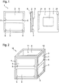
- FIG. 1 is a schematic view of a satellite cover panel 1 according to a first embodiment of the invention from three different sides.
- the satellite cover panel 1 has a flat shape and comprises a battery 2, which is an energy storage device, solar cells 3, which are an energy generating module, and a logic board 4.
- the solar cells 3 define at least partially a first outer surface 6 of the satellite cover panel 1, while the logic board 4 defines a second outer surface 7 of the satellite cover panel 1.
- the area of the first outer surface 6 and the second outer surface 7 is identical. Further, each dimension of the first outer surface 6 and the second outer surface 7 is larger than a thickness of the satellite cover panel 1 measured between the first outer surface 6 and the second outer surface 7. In this way, the flat shape is realized.
- the battery 2 preferably is a structurally integrated battery, which holds the solar cells 3 and the logic board 4.
- the battery 2 is composed of several layers and therefore allows radiation protection. This can be further increased by providing a radiation shield between the battery 2 and the solar cells 3. In this way, the satellite cover panel 1 can protect a payload 15 (see figure 5 ) of a satellite from failure or being damaged due to radiation.
- the solar cells 3 supply electrical energy to the battery 2.
- the battery 2 stores the electrical energy and supplies it to the logic board 4 and/or the payload 15.
- the logic board 4 therefore is electrically connected with the battery 2.
- the logic board 4 further comprises a connecting element 8 for connecting the logic board 4 to the payload. In this way, the payload 15 can be supplied with power.
- the connecting element 8 also allows connecting the logic board 4 to a logic board 4 of another satellite cover panel 1. In this way, two satellite cover panels 1 can be coupled. This leads to increased battery capacity, increased redundancy and/or increased performance of the logic boards 4.
- the logic board 4 comprises a microprocessor 9, which is a main control unit for controlling a satellite 10 (see figure 2 ) equipped with the satellite cover panel 1. Further, the logic board 4 comprises sensors 5 and a not shown attitude control system.
- the sensors 5 extend through the first outer surface and therefore have access to an outside of the satellite 10.
- the sensors 5 particularly might determine an orientation of at least one axis of the satellite cover panel 1 and therefore of the satellite 10. As described above, in case more than one satellite cover panel 1 are provided, redundancy is increased such that failure of one of the sensors 5 does not lead to failure of the whole satellite.
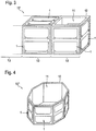
- the satellite 10 comprises six satellite cover panels 1, wherein one of the satellite cover panels 1 is not shown.
- the satellite cover panels 1 are mounted to a frame 12 but are also mechanically coupled in order to stiffen the frame 12. Therefore, the satellite 10 is built in a very solid way.
- the satellite cover panels 1 are mounted such that the solar cells 3 face towards an outside of the satellite 10, while the logic boards 4 face towards a payload bay 11 inside the satellite 10.
- the solar cells 3 therefore can generate electrical energy to charge the batteries 2, while the batteries 2 can supply energy to a payload (not shown) provided inside the payload bay 11.
- the logic boards 4 are electrically connected via the connecting elements 8. Therefore, the above described advantages regarding redundancy and performance apply.
- the satellite is insensitive against failure of single components like single batteries 2, single solar cells 3 and/or single logic boards 4.
- the satellite 10 can be controlled such that single satellite cover panels 1 are activated or deactivated on demand. Therefore, the overall battery capacity or processing power can be increased or reduced on demand.
- the satellite can have the dimensions of about 10 cm x 10 cm x 10 cm. This is the lowest size for carrying two of space-standard solar cells 3 which have a dimension of 4 cm x 8 cm.
- the design of the satellite 10 is scalable as shown in figures 3 to 5 .
- FIG 3 is a schematic view of a satellite 10' according to a second embodiment of the invention.
- the satellite 10' comprises several modules 13, wherein each module 13 has the dimensions of the satellite 10 according to the first embodiment shown in figure 2 .
- FIG 4 is a schematic view of a satellite 10" according to a third embodiment.
- a number of eight satellite cover panels 1 are provided around the payload bay 11.
- the top and bottom surface of the satellite 1 might be left open to allow the payload, e.g. a camera, having free view out of the satellite 10" or might be covered with a conventional cover member.
- a satellite 10''' according to a fourth embodiment of the invention, which includes a payload 15 is shown.
- the satellite 10''' comprises several modules 13 as shown in figure 3 .
- not all satellite cover panels 1 are shown in order to illustrate the payload 15.
- the only part of the satellite 10''' not covered by satellite cover panels 1 is the opening 14.
- the opening 14 is required to allow a lens system 16 of the payload 15 to view out of the payload bay 11.
- Such an opening 14 can therefore be provided in a simple manner by not covering the respective part of the satellite 10 by a satellite cover panel 1.
- the main advantage of the satellite cover panel 1 is the scalable design of satellites 10 equipped with such satellite cover panels 1. Further, the satellite 10 can be designed in a modular way. Redundancy and performance as well as battery capacity are increased by including a further satellite cover panel 1. Additionally, the satellite cover panel 1 can be provided like any ordinary cover panel such that the manufacturing process of the satellite 10 is rather simple and cost saving. This even allows satellite mass production to further reduce costs and manufacturing time.
- Figure 6 is a schematic view of a satellite cover panel 1' according to a second embodiment of the invention.
- the second embodiment differs from the first embodiment only in that the satellite cover panel 1' is symmetrical to a center axis (not shown) perpendicular to the satellite cover panel 1' (i.e. perpendicular to the drawing plane). This means that the center axis is perpendicular to the first outer surface 6 and the second outer surface 7.
- the satellite cover panel 1' further comprises four connection means 21 for interconnecting the logic board 4 and/or the energy storage module 2 to logic boards 4 and/or energy storage modules 2 of adjacent satellite cover panels 1' (not shown) and/or the payload of a satellite comprising said satellite cover panel 1'.
- FIG 7 is a schematic view of a satellite 10'''' according to a fifth embodiment of the invention.
- the fifth embodiment is basically identical to the first embodiment as shown in figure 2 .
- the satellite cover panel 1 comprises a holding element 20 having a first portion 17, a second portion 18, and a hinge 19 connecting the first portion 17 and the second portion 18. This allows folding and unfolding of the holding element 20.
- the first portion 17 comprises energy generating modules 3 which at least partially define the first outer surface 6.
- the second portion 18 comprises further energy generating modules 3', which do not define the first outer surface 6. Due to such a design, the energy generating capacity is increased since the total number of energy generating modules 3, 3' is increased.
- the satellite 10'''' according to the fifth embodiment is preferable adapted to point the second portions 18 comprising the further energy generating modules 3' directly towards the sun. Hence, the further energy generating modules 3' are placed for optimal energy generation.
- the holding element 20 can be transferred to a folded state, in which the first portions 17 and the second portion 18 face each other.
- the satellite 10'''' according to the fifth embodiment maintains the cubic shape like in the first embodiment.
- the satellite 10'''' according to the fifth embodiment is transferred to a shape as shown in figure 7 .
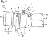
- FIG 8 is a schematic view of a satellite 10'''' according to a sixth embodiment of the invention.
- the sixth embodiment differs from the fifth embodiment only in that the hinge 19 is orientated in a different way. This allows the second portions 18 to be folded such that they face away from all first portions 17, i.e. even those first portions 17 the respective second portion 18 is not connected to. This allows converting the satellite 10''''' to a so called x-wing configuration.
- the x-wing configuration allows optimized energy generation via the energy generating modules 3, 3' without transferring the satellite 10'''''' to a specific orientation towards the sun.
Landscapes
- Engineering & Computer Science (AREA)
- Remote Sensing (AREA)
- Aviation & Aerospace Engineering (AREA)
- Life Sciences & Earth Sciences (AREA)
- Sustainable Development (AREA)
- Physics & Mathematics (AREA)
- Astronomy & Astrophysics (AREA)
- General Physics & Mathematics (AREA)
- Photovoltaic Devices (AREA)
Abstract
Description
- The invention regards a satellite cover panel. Further, the invention regards a satellite comprising at least one satellite cover panel. The satellite cover panel allows covering a satellite, particularly a payload bay of a satellite.
- From the prior art, satellites are known which comprise several subsystems. The subsystems are connected according to a satellite bus via cable harness and/or plug connection. Such subsystems particularly comprise an energy supply subsystem, a main control subsystem, an attitude control subsystem, and a communication subsystem.
- Such a design requires a lot of room inside the satellite such that either the payload mass is reduced and/or the volume and/or weight of the satellite increases, which leads to increased costs when transporting the satellite to space. Further, all subsystems are implemented and manufactured individually. This also leads to the drawback that features of different subsystems can not cooperate easily to increase the redundancy and/or computing capacity.
- An object of the invention is to provide a satellite cover panel, which is simple to manufacture, which protects the payload, which provides major/some/all features of a satellite bus and which allows increasing the payload volume.
- The solution of this object is provided by the features of
independent claim 1. The dependent claims contain advantageous embodiments of the present invention. - The object is therefore solved by a satellite cover panel for covering a satellite, particularly a payload bay of a satellite comprising an energy storage module, at least one energy generating module, preferably at least one solar cell, and a logic board. The energy generating module defines, at least partially, a first outer surface of the satellite cover panel. The logic board on the other side defines, at least partially, a second outer surface of the satellite cover panel. The first outer surface and the second outer surface face away from each other and from the energy storage module. Therefore, the energy generating module and the logic board each are provided on an outer side of the satellite cover panel, while the energy storage module is provided in between the energy generating module and the logic board. The energy storage module allows radiation protection of the interior space of the satellite, particularly of the payload bay covered by the satellite cover panel. In a preferred embodiment of the invention, the energy storage module holds the at least one energy generating module and the logic board. This leads to a stiff and solid design of the satellite cover panel. The satellite cover panel therefore helps to reinforce the design of a satellite provided with the satellite cover panel. Particularly, the first outer surface and the second outer surface cover the same area or differ in area of at most 20%, preferably at most 10%. The energy storage module preferably does not extend over the edges of the first outer surface or the second outer surface. In this way, a panel is provided which can be used as any ordinary cover panel. However, the satellite cover panel includes functionality which at least partially can replace the subsystems provided in an ordinary satellite. Therefore, the payload volume is increased since less or no conventional subsystems are required when adopting the satellite cover panels according to the present invention.
- In a preferred embodiment, the dimensions of the first outer surface and the second outer surface are larger than a thickness measured between the first outer surface and the second outer surface. In this way, a panel shape is realized. The first outer surface and the second outer surface therefore are the largest surfaces of the satellite cover panel. The satellite cover panel can have the same dimensions than any ordinary cover panel. For instance, the satellite cover panel can have a minimum size of 5 cm x 5 cm, wherein the thickness is less than 20%, preferably less than 10% of the side length. Preferably, the energy generating module comprises one or two or more solar cells, wherein each solar cell may have a dimension of 4 cm x 8 cm with a thickness smaller than 1 mm. Those dimensions are common for satellites, such that particularly standard solar cells can be adopted for the satellite cover panel.
- The energy storage module preferably is a battery, particularly a structurally integrated battery. Due to the battery's layer composition, an improved radiation protection is established. Therefore, the satellite cover panel can efficiently cover a payload and/or other sections of interior space of the satellite and protect the payload and/or other sections of interior space of the satellite from radiation. The battery preferably has a flat shape such that the satellite cover panel also has a flat shape. Particularly by using structurally integrated batteries, the satellite cover panel can have a flat design while at the same time being built in a solid way. In order to further increase the radiation protection, the satellite cover panel may comprise at least one further radiation shield layer, which might be provided between the at least one energy generating module and the energy storage module and/or between the energy storage module and the logic board. The energy storage module may comprise one, two or more energy storage devices, particularly one, two or more batteries.
- The logic board preferably comprises at least one sensor for detecting an orientation of at least one axis of the satellite cover panel. The sensor allows attitude determination to realize attitude control of the whole satellite regarding at least one axis of the satellite. For attitude control, data of sensors of logic boards from at least two different satellite cover panels might be combined. Further, the sensor preferably allows self-configuration after the satellite cover panel is provided to the satellite. In case more than one satellite cover panel are provided, redundancy is increased since each sensor can independently detect an orientation of the satellite cover panel and therefore of the satellite.
- Additionally or alternatively, the logic board preferably comprises an attitude control system for controlling an orientation of the satellite cover panel. Again, redundancy and simultaneously controllable axis number can be increased by providing more than one satellite cover panels. Favorably, the attitude control system includes a magnetic field based actuator system.
- In another preferred embodiment, the logic board comprises a microprocessor. The microprocessor is a main control unit which allows controlling the functionality of the satellite equipped with the satellite cover panel and/or a payload of the satellite. Again, the redundancy can be increased by providing more than one satellite cover panel. Instead of redundancy, performance of the microprocessor can be increased by combining several microprocessors of the satellite cover panels. In order to connect satellite cover panels among each other, the logic board particularly comprises a connecting element. The connecting element is adapted to connect the logic board to another logic board and/or to a payload provided in the payload bay. Therefore, the satellite bus according to the prior art definition is completely provided in the cover panels of the satellite. This increases the volume of the payload such that the satellite is more efficient.
- The satellite cover panel favorably is symmetrical with respect to a center axis perpendicular to the satellite cover panel. Said center axis particularly extends perpendicular to the first outer surface and the second outer surface.
- Preferably, the satellite cover panel comprises at least one connection means on at least one outer side, preferably on each outer side for connecting the logic board and/or the energy storage module to a logic board and/or to an energy storage module of another/other satellite cover panel(s) and/or to a payload provided in the payload bay.
- The satellite cover panel preferably comprises a holding element having a first portion and a second portion connected via a hinge. This design allows folding and unfolding the holding element. The first portion may hold the at least one energy generating module, which defines, at least partially, the first outer surface. The second portion may hold at least one additional energy generating module. In case the holding element is folded, the first portion and the second portion are facing each other. Accordingly, the at least one energy generating module defining, at least partially, the first surface is covered by the second portion of the holding element. In case the holding element is unfolded, the surface for providing energy generating modules is increased, such that an increased generation of energy is possible.
- The invention further regards a satellite comprising a frame. The satellite comprises at least one satellite cover panel as described above. The at least one satellite cover panel is mounted to the frame to set up an outer surface of the satellite. Therefore, the frame preferably is covered by the satellite cover panels. The satellite cover panels particularly are the only elements visible from outside the satellite. In a preferred embodiment of the invention the satellite comprises at least two, more preferably at least three and most preferably at least four satellite cover panels as described above.
- Preferably, in a mounted state the first outer surface of each satellite cover panel faces away from the frame. Additionally or alternatively, in a mounted state the second outer surface of each satellite over panel faces towards the frame. The first outer surface comprises the at least one energy generating module, preferably the at least one solar cell. This energy generating module therefore allows providing the satellite with energy. The energy is stored within the energy storage module of each satellite cover panel and can be supplied to the payload and/or to the logic board of the satellite cover panel.
- Preferably, the logic boards of at least some of all satellite cover panels are interconnected. Therefore, the satellite cover panels are electrically coupled. This allows exchanging data between the logic boards of the satellite cover panels. The interconnection allows increased redundancy on the one hand and/or increased performance on the other hand. Therefore, the satellite comprising the satellite cover panels according to the invention can be set up in a very flexible and scalable way. It is possible to increase redundancy by controlling the microprocessors and/or sensors and/or attitude control systems individually. In this case, damage or failure of one of these components does not lead to failure of the whole satellite. On the other hand, several microprocessors can be combined to increase the calculation performance. This allows employing rather cheap hardware with low performance, since the combination of the microprocessors leads to increased performance. Further, in case an increased performance is not needed, it is possible to activate and deactivate single logic boards or whole satellite cover panels on demand. Independent from single logic boards or whole satellite cover panels being active or inactive, the satellite cover panels preferably all the time ensure at least partial radiation protection and cover of the payload.
- In addition or alternatively, the energy storage modules of at least some of all satellite cover panels may be interconnected. The interconnection allows increased redundancy on the one hand and/or increased energy storage capacity on the other hand. In case an increased energy storing capacity is not needed, it is possible to activate and deactivate single energy storage modules or whole satellite cover panels on demand. Independent from the energy storage module or the whole satellite cover panel being active or inactive, the satellite cover panels all the time ensure radiation protection and cover of the payload.
- Preferably, the satellite cover panels are fixed to each other to stiffen the frame. Therefore, the satellite cover panels may be mechanically coupled. The frame itself does not have to bear the entire load generated by the payload. Therefore, the satellite is very solid and insensitive against mechanical influences.
- The radiation protection provided by the satellite cover panel and/or the increased redundancy allows employing logic bards that include components which are not specifically designed for use in space. This simplifies manufacturing of the logic boards and of the satellite cover panels and reduces the manufacturing costs.
- The frame preferably defines a payload bay, in which a payload can be provided. The at least one satellite cover panel is mounted to the frame to cover the payload bay. The payload bay is at least partially covered by satellite cover panels as described above. Particularly, the payload bay might require an opening to allow receiving data from outside. This might be the case if the payload is a camera; the lens system should not be covered or concealed by the satellite cover panel. Such an opening can be established by not providing a satellite cover panel to a respective portion of the frame.
- Preferably, in a mounted state the first outer surface of each satellite cover panel faces away from the payload bay. Additionally or alternatively, in a mounted state the second outer surface of each satellite over panel faces towards the payload bay. Therefore, the first outer surface, which includes the at least one energy generating module, preferably the at least one solar cell, is arranged to face an outside of the satellite. This allows the energy generating module(s) generating energy from luminous energy.
- The satellite may also comprise cover panels other than the above described cover panels. In this case, these cover panels may not provide any further function. There might be cover panels provided for radiation protection only. That means, the satellite can comprise ordinary cover panels according to the prior art. Preferably, the different cover panels can all be exchanged with each other. Particularly, the above described satellite cover panel can be exchanged with any ordinary cover panel. This allows an effective mass production of satellites such that the manufacturing costs of satellites are reduced.
- Further details and advantages of the invention are described together with the attached drawings. In the drawings
- Fig. 1
- is a schematic view of a satellite cover panel according to a first embodiment of the invention from three different sides,
- Fig. 2
- is a schematic view of a satellite according to a first embodiment of the invention,
- Fig. 3
- is a schematic view of a satellite according to a second embodiment of the invention,
- Fig. 4
- is a schematic view of a satellite according to a third embodiment of the invention,
- Fig. 5
- is a schematic view of a satellite according to a fourth embodiment of the invention,
- Fig. 6
- is a schematic view of a satellite cover panel according to a second embodiment of the invention,
- Fig. 7
- is a schematic view of a satellite according to a fifth embodiment of the invention, and
- Fig. 8
- is a schematic view of a satellite according to a sixth embodiment of the invention.
-
Figure 1 is a schematic view of asatellite cover panel 1 according to a first embodiment of the invention from three different sides. Thesatellite cover panel 1 has a flat shape and comprises abattery 2, which is an energy storage device,solar cells 3, which are an energy generating module, and alogic board 4. Thesolar cells 3 define at least partially a firstouter surface 6 of thesatellite cover panel 1, while thelogic board 4 defines a secondouter surface 7 of thesatellite cover panel 1. The area of the firstouter surface 6 and the secondouter surface 7 is identical. Further, each dimension of the firstouter surface 6 and the secondouter surface 7 is larger than a thickness of thesatellite cover panel 1 measured between the firstouter surface 6 and the secondouter surface 7. In this way, the flat shape is realized. - The
battery 2 preferably is a structurally integrated battery, which holds thesolar cells 3 and thelogic board 4. Thebattery 2 is composed of several layers and therefore allows radiation protection. This can be further increased by providing a radiation shield between thebattery 2 and thesolar cells 3. In this way, thesatellite cover panel 1 can protect a payload 15 (seefigure 5 ) of a satellite from failure or being damaged due to radiation. - The
solar cells 3 supply electrical energy to thebattery 2. Thebattery 2 stores the electrical energy and supplies it to thelogic board 4 and/or thepayload 15. Thelogic board 4 therefore is electrically connected with thebattery 2. Thelogic board 4 further comprises a connecting element 8 for connecting thelogic board 4 to the payload. In this way, thepayload 15 can be supplied with power. - The connecting element 8 also allows connecting the
logic board 4 to alogic board 4 of anothersatellite cover panel 1. In this way, twosatellite cover panels 1 can be coupled. This leads to increased battery capacity, increased redundancy and/or increased performance of thelogic boards 4. - The
logic board 4 comprises amicroprocessor 9, which is a main control unit for controlling a satellite 10 (seefigure 2 ) equipped with thesatellite cover panel 1. Further, thelogic board 4 comprisessensors 5 and a not shown attitude control system. Thesensors 5 extend through the first outer surface and therefore have access to an outside of thesatellite 10. Thesensors 5 particularly might determine an orientation of at least one axis of thesatellite cover panel 1 and therefore of thesatellite 10. As described above, in case more than onesatellite cover panel 1 are provided, redundancy is increased such that failure of one of thesensors 5 does not lead to failure of the whole satellite. - In
figures 2 ,3 ,4 , and5 , different embodiments of asatellite 10 are shown. In a first embodiment shown infigure 2 , thesatellite 10 comprises sixsatellite cover panels 1, wherein one of thesatellite cover panels 1 is not shown. Thesatellite cover panels 1 are mounted to aframe 12 but are also mechanically coupled in order to stiffen theframe 12. Therefore, thesatellite 10 is built in a very solid way. - The
satellite cover panels 1 are mounted such that thesolar cells 3 face towards an outside of thesatellite 10, while thelogic boards 4 face towards apayload bay 11 inside thesatellite 10. Thesolar cells 3 therefore can generate electrical energy to charge thebatteries 2, while thebatteries 2 can supply energy to a payload (not shown) provided inside thepayload bay 11. - The
logic boards 4 are electrically connected via the connecting elements 8. Therefore, the above described advantages regarding redundancy and performance apply. Particularly, the satellite is insensitive against failure of single components likesingle batteries 2, singlesolar cells 3 and/orsingle logic boards 4. Further, thesatellite 10 can be controlled such that singlesatellite cover panels 1 are activated or deactivated on demand. Therefore, the overall battery capacity or processing power can be increased or reduced on demand. - In the first embodiment, the satellite can have the dimensions of about 10 cm x 10 cm x 10 cm. This is the lowest size for carrying two of space-standard
solar cells 3 which have a dimension of 4 cm x 8 cm. However, the design of thesatellite 10 is scalable as shown infigures 3 to 5 . -
Figure 3 is a schematic view of a satellite 10' according to a second embodiment of the invention. The satellite 10' comprisesseveral modules 13, wherein eachmodule 13 has the dimensions of thesatellite 10 according to the first embodiment shown infigure 2 . By adding furthersatellite cover panels 1, redundancy and performance is further increased. -
Figure 4 is a schematic view of asatellite 10" according to a third embodiment. In this embodiment, a number of eightsatellite cover panels 1 are provided around thepayload bay 11. The top and bottom surface of thesatellite 1 might be left open to allow the payload, e.g. a camera, having free view out of thesatellite 10" or might be covered with a conventional cover member. - In
Figure 5 , a satellite 10''' according to a fourth embodiment of the invention, which includes apayload 15 is shown. Again, the satellite 10''' comprisesseveral modules 13 as shown infigure 3 . Infigure 5 , not allsatellite cover panels 1 are shown in order to illustrate thepayload 15. The only part of the satellite 10''' not covered bysatellite cover panels 1 is theopening 14. Theopening 14 is required to allow alens system 16 of thepayload 15 to view out of thepayload bay 11. Such anopening 14 can therefore be provided in a simple manner by not covering the respective part of thesatellite 10 by asatellite cover panel 1. - The main advantage of the
satellite cover panel 1 is the scalable design ofsatellites 10 equipped with suchsatellite cover panels 1. Further, thesatellite 10 can be designed in a modular way. Redundancy and performance as well as battery capacity are increased by including a furthersatellite cover panel 1. Additionally, thesatellite cover panel 1 can be provided like any ordinary cover panel such that the manufacturing process of thesatellite 10 is rather simple and cost saving. This even allows satellite mass production to further reduce costs and manufacturing time. -
Figure 6 is a schematic view of a satellite cover panel 1' according to a second embodiment of the invention. The second embodiment differs from the first embodiment only in that the satellite cover panel 1' is symmetrical to a center axis (not shown) perpendicular to the satellite cover panel 1' (i.e. perpendicular to the drawing plane). This means that the center axis is perpendicular to the firstouter surface 6 and the secondouter surface 7. The satellite cover panel 1' further comprises four connection means 21 for interconnecting thelogic board 4 and/or theenergy storage module 2 tologic boards 4 and/orenergy storage modules 2 of adjacent satellite cover panels 1' (not shown) and/or the payload of a satellite comprising said satellite cover panel 1'. -
Figure 7 is a schematic view of a satellite 10'''' according to a fifth embodiment of the invention. The fifth embodiment is basically identical to the first embodiment as shown infigure 2 . However, in the fifth embodiment, thesatellite cover panel 1 comprises a holdingelement 20 having afirst portion 17, asecond portion 18, and ahinge 19 connecting thefirst portion 17 and thesecond portion 18. This allows folding and unfolding of the holdingelement 20. - The
first portion 17 comprisesenergy generating modules 3 which at least partially define the firstouter surface 6. Thesecond portion 18 comprises furtherenergy generating modules 3', which do not define the firstouter surface 6. Due to such a design, the energy generating capacity is increased since the total number ofenergy generating modules second portions 18 comprising the furtherenergy generating modules 3' directly towards the sun. Hence, the furtherenergy generating modules 3' are placed for optimal energy generation. - The holding
element 20 can be transferred to a folded state, in which thefirst portions 17 and thesecond portion 18 face each other. In this state, the satellite 10'''' according to the fifth embodiment maintains the cubic shape like in the first embodiment. In an unfolded state, the satellite 10'''' according to the fifth embodiment is transferred to a shape as shown infigure 7 . -
Figure 8 is a schematic view of a satellite 10'''' according to a sixth embodiment of the invention. The sixth embodiment differs from the fifth embodiment only in that thehinge 19 is orientated in a different way. This allows thesecond portions 18 to be folded such that they face away from allfirst portions 17, i.e. even thosefirst portions 17 the respectivesecond portion 18 is not connected to. This allows converting the satellite 10''''' to a so called x-wing configuration. The x-wing configuration allows optimized energy generation via theenergy generating modules -
- 1,1'
- satellite cover panel
- 2
- energy storage module
- 3, 3'
- energy generating module (solar cell)
- 4
- logic board
- 5
- sensors
- 6
- first outer surface
- 7
- second outer surface
- 8
- connecting element
- 9
- microprocessor
- 10, 10', 10", 10''', 10'''', 10'''''
- satellite
- 11
- payload bay
- 12
- frame
- 13
- module
- 14
- opening
- 15
- payload (camera)
- 16
- lens system
- 17
- first portion
- 18
- second portion
- 19
- hinge
- 20
- holding element
- 21
- connection means
Claims (15)
- Satellite cover panel (1) for covering a satellite, particularly a payload bay (11) of a satellite (10) comprising• an energy storage module (2)• at least one energy generating module (3) defining, at least partially, a first outer surface (6) of the satellite cover panel (1),• a logic board (4) defining, at least partially, a second outer surface (7) of the satellite cover panel (1),• wherein the first outer surface (6) and the second outer surface (7) face away from each other and from the energy storage module (2).
- Satellite cover panel (1) according to claim 1, characterized in that the dimensions of the first outer surface (6) and the second outer surface (7) are larger than a thickness measured between the first outer surface (6) and the second outer surface (7).
- Satellite cover panel (1) according to any one of the previous claims, characterized in that the energy storage module (2) is a battery, particularly a structurally integrated battery.
- Satellite cover panel (1) according to any one of the previous claims characterized in that the logic board (4) comprises at least one sensor for detecting an orientation of the satellite cover panel (1) and/or that the logic board (4) comprises an attitude control system for controlling an orientation of the satellite cover panel (1).
- Satellite cover panel (1) according to any one of the previous claims, characterized in that the logic board (4) comprises a microprocessor (9) and/or a connecting element (8) for connecting the logic board (4) to another logic board (4) and/or to a payload provided in the payload bay (11).
- Satellite cover panel (1) according to any one of the previous claims, characterized in that the satellite cover panel (1) is symmetrical with respect to a center axis perpendicular to the satellite cover panel (1).
- Satellite cover panel (1) according to any of the previous claims, characterized in that the satellite cover panel (1) comprises at least one connection means (21) on at least one outer side for connecting the logic board (4) and/or the energy storage module (2) to a logic board (4) and/or to an energy storage module (2) of another/other satellite cover panel(s) (1) and/or to a payload provided in the payload bay (11).
- Satellite cover panel (1) according to any one of the previous claims, characterized in that the satellite cover panel (1) comprises a holding element (20) having a first portion (17) and a second portion (18) connected via a hinge (19) to fold and unfold the holding element (20), wherein the first portion (17) preferably holds the at least one energy generating module (3), which defines, at least partially, the first outer surface (6), and the second portion (18) preferably holds at least one additional energy generating module (3').
- Satellite (10) comprising a frame (12) and at least one satellite cover panel (1) according to any one of the previous claims, wherein the at least one satellite cover panel (1) is mounted to the frame (12) to set up an outer surface of the satellite (10).
- Satellite (10) according to claim 9, characterized in that the first outer surface (6) of each satellite cover panel (1) faces away from the frame (12) and/or the second outer surface (7) faces towards the frame (12).
- Satellite (10) according to claim 9 or 10, characterized in that the logic boards (4) of at least some of all satellite cover panels (1) are interconnected for establishing redundancy and/or increased performance.
- Satellite (10) according to any one of claims 9 to 11, characterized in that the energy storage modules (3, 6) of at least some of all satellite cover panels (1) are interconnected for establishing redundancy and/or increased performance.
- Satellite (10) according to any one of claims 9 to 12, characterized in that the satellite cover panels (1) are fixed to each other to stiffen the frame (12).
- Satellite (10) according to any one of claims 9 to 13, characterized in that the frame (12) defines a payload bay (11), wherein the at least one satellite cover panel (1) is mounted to the frame (12) to cover the payload bay (11).
- Satellite (10) according to claim 14, characterized in that the first outer surface (6) of each satellite cover panel (1) faces away from the payload bay (11) and/or the second outer surface (7) of each satellite cover panel (1) faces towards the payload bay (11).
Priority Applications (2)
| Application Number | Priority Date | Filing Date | Title |
|---|---|---|---|
| EP17182497.2A EP3431398B1 (en) | 2017-07-21 | 2017-07-21 | Satellite cover panel |
| US16/042,454 US11097858B2 (en) | 2017-07-21 | 2018-07-23 | Satellite cover panel |
Applications Claiming Priority (1)
| Application Number | Priority Date | Filing Date | Title |
|---|---|---|---|
| EP17182497.2A EP3431398B1 (en) | 2017-07-21 | 2017-07-21 | Satellite cover panel |
Publications (2)
| Publication Number | Publication Date |
|---|---|
| EP3431398A1 true EP3431398A1 (en) | 2019-01-23 |
| EP3431398B1 EP3431398B1 (en) | 2019-09-11 |
Family
ID=59384026
Family Applications (1)
| Application Number | Title | Priority Date | Filing Date |
|---|---|---|---|
| EP17182497.2A Active EP3431398B1 (en) | 2017-07-21 | 2017-07-21 | Satellite cover panel |
Country Status (2)
| Country | Link |
|---|---|
| US (1) | US11097858B2 (en) |
| EP (1) | EP3431398B1 (en) |
Cited By (1)
| Publication number | Priority date | Publication date | Assignee | Title |
|---|---|---|---|---|
| FR3157357A1 (en) * | 2023-12-21 | 2025-06-27 | Universite De Montpellier | Modular internal structure of a CubeSat-type nanosatellite |
Families Citing this family (13)
| Publication number | Priority date | Publication date | Assignee | Title |
|---|---|---|---|---|
| ITUB20152728A1 (en) * | 2015-07-31 | 2017-01-31 | D Orbit S R L | PROPULSION SYSTEM FOR SMALL ARTIFICIAL SATELLITES OF SMALL DIMENSIONS, INCORPORATING SATELLITES OF THE PROPULSION SYSTEM AND METHOD OF MANAGEMENT OF THAT PROPULSION SYSTEM |
| US11794927B2 (en) | 2019-08-28 | 2023-10-24 | The Boeing Company | Additively manufactured spacecraft panel |
| US11878816B2 (en) * | 2019-09-20 | 2024-01-23 | Scott Weintraub | Reusable modular spacecraft and related systems |
| US11827389B2 (en) * | 2020-05-18 | 2023-11-28 | The Boeing Company | Additively manufactured satellite |
| US11802606B2 (en) | 2020-05-18 | 2023-10-31 | The Boeing Company | Planate dynamic isolator |
| CA3140352A1 (en) | 2020-12-17 | 2022-06-17 | The Boeing Company | Stacked satellite assemblies and related methods |
| CA3140350A1 (en) | 2020-12-17 | 2022-06-17 | The Boeing Company | Satellite thermal enclosure |
| US12509252B2 (en) * | 2021-11-17 | 2025-12-30 | Outpost Technologies Corporation | Space vehicles with paraglider re-entry, and associated systems and methods |
| US12358656B2 (en) * | 2022-05-31 | 2025-07-15 | Sidus Space, Inc. | System for a modular satellite testing platform |
| CN115158699A (en) * | 2022-07-21 | 2022-10-11 | 上海卫星工程研究所 | Satellite structure for double-satellite parallel launching and satellite carrier rocket |
| TR2022013588A1 (en) * | 2022-08-31 | 2024-03-21 | Tusas Tuerk Havacilik Ve Uzay Sanayii Anonim Sirketi | A thermal protection system. |
| CN116923737A (en) * | 2023-05-25 | 2023-10-24 | 北京卫星环境工程研究所 | Flexible gown for spacecraft |
| CN119683010B (en) * | 2024-11-27 | 2025-10-28 | 上海宇航系统工程研究所 | Large-scale load cabin section of space station |
Citations (6)
| Publication number | Priority date | Publication date | Assignee | Title |
|---|---|---|---|---|
| EP1559649A1 (en) * | 2002-10-24 | 2005-08-03 | Shinichi Nakasuka | Artificial satellite |
| US20060105706A1 (en) * | 2004-11-16 | 2006-05-18 | Huang James P | System and method incorporating adaptive and reconfigurable cells |
| US7474249B1 (en) * | 2004-08-12 | 2009-01-06 | Lockheed Martin Corporation | Systems and methods for dedicating power to a radar module |
| EP2386489A2 (en) * | 2010-05-14 | 2011-11-16 | Japan Aerospace Exploration Agency | Panel type artificial satellite and artificial satellite system therewith |
| US20140039729A1 (en) * | 2012-08-06 | 2014-02-06 | Jordi Puig-Suari | Cubesat system, method and apparatus |
| EP3109171A1 (en) * | 2015-06-24 | 2016-12-28 | Airbus DS GmbH | Modular satellite device support panel and modular satellite |
Family Cites Families (2)
| Publication number | Priority date | Publication date | Assignee | Title |
|---|---|---|---|---|
| US7963397B2 (en) * | 2006-02-09 | 2011-06-21 | Seagle Vance L | Modular, knock-down, light weight, thermally insulating, tamper proof shipping container and fire retardant shipping container bag |
| US10315784B2 (en) * | 2016-11-23 | 2019-06-11 | Matthew J Leonard | System for increasing storage volume of a CubeSat |
-
2017
- 2017-07-21 EP EP17182497.2A patent/EP3431398B1/en active Active
-
2018
- 2018-07-23 US US16/042,454 patent/US11097858B2/en not_active Expired - Fee Related
Patent Citations (6)
| Publication number | Priority date | Publication date | Assignee | Title |
|---|---|---|---|---|
| EP1559649A1 (en) * | 2002-10-24 | 2005-08-03 | Shinichi Nakasuka | Artificial satellite |
| US7474249B1 (en) * | 2004-08-12 | 2009-01-06 | Lockheed Martin Corporation | Systems and methods for dedicating power to a radar module |
| US20060105706A1 (en) * | 2004-11-16 | 2006-05-18 | Huang James P | System and method incorporating adaptive and reconfigurable cells |
| EP2386489A2 (en) * | 2010-05-14 | 2011-11-16 | Japan Aerospace Exploration Agency | Panel type artificial satellite and artificial satellite system therewith |
| US20140039729A1 (en) * | 2012-08-06 | 2014-02-06 | Jordi Puig-Suari | Cubesat system, method and apparatus |
| EP3109171A1 (en) * | 2015-06-24 | 2016-12-28 | Airbus DS GmbH | Modular satellite device support panel and modular satellite |
Cited By (1)
| Publication number | Priority date | Publication date | Assignee | Title |
|---|---|---|---|---|
| FR3157357A1 (en) * | 2023-12-21 | 2025-06-27 | Universite De Montpellier | Modular internal structure of a CubeSat-type nanosatellite |
Also Published As
| Publication number | Publication date |
|---|---|
| EP3431398B1 (en) | 2019-09-11 |
| US11097858B2 (en) | 2021-08-24 |
| US20190023423A1 (en) | 2019-01-24 |
Similar Documents
| Publication | Publication Date | Title |
|---|---|---|
| EP3431398B1 (en) | Satellite cover panel | |
| US20230391476A1 (en) | Solar, electronic, rf radiator for a self-contained structure for space application array | |
| US5979833A (en) | Modular spacecraft architecture | |
| US10454082B2 (en) | Battery rack | |
| US11404905B2 (en) | Self configuring modular electrical system | |
| US20170141369A1 (en) | Advanced Lithium Polymer System (ALPS) | |
| CN108674692A (en) | A kind of remote sensing microsatellite | |
| Pajusalu et al. | Design and pre-flight testing of the electrical power system for the ESTCube-1 nanosatellite | |
| CN102001452B (en) | Method for realizing integration of energy control and main force bearing plate of satellite | |
| CN111699627A (en) | Power wiring device | |
| CN104176272A (en) | Eight-bar connection non-contact satellite platform configuration | |
| CN113788163B (en) | An on-orbit multi-dimensional expansion evolution method for modular satellites | |
| JP2004142592A (en) | Artificial satellite | |
| US20060105706A1 (en) | System and method incorporating adaptive and reconfigurable cells | |
| CN115352651A (en) | Modularized mechanical and thermal integrated service cube satellite system suitable for batch production | |
| KR20170025073A (en) | Battery rack | |
| CN116062196B (en) | Assembling method of cell satellite | |
| JPH10203500A (en) | Functionally independent spacecraft module | |
| CN113772122B (en) | Module unit for satellite | |
| ES2248370T3 (en) | MODULAR REACTION WHEEL ASSEMBLY TO PROTECT ELECTRONICS ON A SATELLITE. | |
| TW201637349A (en) | Photoelectric conversion module group and photoelectric conversion device | |
| RU2688630C2 (en) | Space platform | |
| US12378008B2 (en) | Solar array spring elements for stacking spacecraft | |
| RU2293688C1 (en) | Mini-satellite for cluster and accompanying launch | |
| KR102170823B1 (en) | An Electrical power system of artificial satellite having a separable battery package |
Legal Events
| Date | Code | Title | Description |
|---|---|---|---|
| PUAI | Public reference made under article 153(3) epc to a published international application that has entered the european phase |
Free format text: ORIGINAL CODE: 0009012 |
|
| STAA | Information on the status of an ep patent application or granted ep patent |
Free format text: STATUS: REQUEST FOR EXAMINATION WAS MADE |
|
| 17P | Request for examination filed |
Effective date: 20180514 |
|
| AK | Designated contracting states |
Kind code of ref document: A1 Designated state(s): AL AT BE BG CH CY CZ DE DK EE ES FI FR GB GR HR HU IE IS IT LI LT LU LV MC MK MT NL NO PL PT RO RS SE SI SK SM TR |
|
| AX | Request for extension of the european patent |
Extension state: BA ME |
|
| RIC1 | Information provided on ipc code assigned before grant |
Ipc: B64G 1/44 20060101ALI20190207BHEP Ipc: B64G 1/42 20060101ALI20190207BHEP Ipc: B64G 1/10 20060101AFI20190207BHEP Ipc: B64C 1/12 20060101ALI20190207BHEP Ipc: B64G 1/22 20060101ALI20190207BHEP Ipc: B64C 3/26 20060101ALI20190207BHEP |
|
| GRAP | Despatch of communication of intention to grant a patent |
Free format text: ORIGINAL CODE: EPIDOSNIGR1 |
|
| STAA | Information on the status of an ep patent application or granted ep patent |
Free format text: STATUS: GRANT OF PATENT IS INTENDED |
|
| INTG | Intention to grant announced |
Effective date: 20190319 |
|
| GRAS | Grant fee paid |
Free format text: ORIGINAL CODE: EPIDOSNIGR3 |
|
| GRAA | (expected) grant |
Free format text: ORIGINAL CODE: 0009210 |
|
| STAA | Information on the status of an ep patent application or granted ep patent |
Free format text: STATUS: THE PATENT HAS BEEN GRANTED |
|
| RIN1 | Information on inventor provided before grant (corrected) |
Inventor name: LANGER, MARTIN Inventor name: GRUEBLER, THOMAS |
|
| AK | Designated contracting states |
Kind code of ref document: B1 Designated state(s): AL AT BE BG CH CY CZ DE DK EE ES FI FR GB GR HR HU IE IS IT LI LT LU LV MC MK MT NL NO PL PT RO RS SE SI SK SM TR |
|
| REG | Reference to a national code |
Ref country code: GB Ref legal event code: FG4D |
|
| REG | Reference to a national code |
Ref country code: CH Ref legal event code: EP |
|
| REG | Reference to a national code |
Ref country code: AT Ref legal event code: REF Ref document number: 1178146 Country of ref document: AT Kind code of ref document: T Effective date: 20190915 |
|
| REG | Reference to a national code |
Ref country code: DE Ref legal event code: R096 Ref document number: 602017006902 Country of ref document: DE |
|
| REG | Reference to a national code |
Ref country code: IE Ref legal event code: FG4D |
|
| REG | Reference to a national code |
Ref country code: NL Ref legal event code: MP Effective date: 20190911 |
|
| REG | Reference to a national code |
Ref country code: LT Ref legal event code: MG4D |
|
| PG25 | Lapsed in a contracting state [announced via postgrant information from national office to epo] |
Ref country code: FI Free format text: LAPSE BECAUSE OF FAILURE TO SUBMIT A TRANSLATION OF THE DESCRIPTION OR TO PAY THE FEE WITHIN THE PRESCRIBED TIME-LIMIT Effective date: 20190911 Ref country code: LT Free format text: LAPSE BECAUSE OF FAILURE TO SUBMIT A TRANSLATION OF THE DESCRIPTION OR TO PAY THE FEE WITHIN THE PRESCRIBED TIME-LIMIT Effective date: 20190911 Ref country code: BG Free format text: LAPSE BECAUSE OF FAILURE TO SUBMIT A TRANSLATION OF THE DESCRIPTION OR TO PAY THE FEE WITHIN THE PRESCRIBED TIME-LIMIT Effective date: 20191211 Ref country code: NO Free format text: LAPSE BECAUSE OF FAILURE TO SUBMIT A TRANSLATION OF THE DESCRIPTION OR TO PAY THE FEE WITHIN THE PRESCRIBED TIME-LIMIT Effective date: 20191211 Ref country code: HR Free format text: LAPSE BECAUSE OF FAILURE TO SUBMIT A TRANSLATION OF THE DESCRIPTION OR TO PAY THE FEE WITHIN THE PRESCRIBED TIME-LIMIT Effective date: 20190911 Ref country code: SE Free format text: LAPSE BECAUSE OF FAILURE TO SUBMIT A TRANSLATION OF THE DESCRIPTION OR TO PAY THE FEE WITHIN THE PRESCRIBED TIME-LIMIT Effective date: 20190911 |
|
| PG25 | Lapsed in a contracting state [announced via postgrant information from national office to epo] |
Ref country code: RS Free format text: LAPSE BECAUSE OF FAILURE TO SUBMIT A TRANSLATION OF THE DESCRIPTION OR TO PAY THE FEE WITHIN THE PRESCRIBED TIME-LIMIT Effective date: 20190911 Ref country code: GR Free format text: LAPSE BECAUSE OF FAILURE TO SUBMIT A TRANSLATION OF THE DESCRIPTION OR TO PAY THE FEE WITHIN THE PRESCRIBED TIME-LIMIT Effective date: 20191212 Ref country code: ES Free format text: LAPSE BECAUSE OF FAILURE TO SUBMIT A TRANSLATION OF THE DESCRIPTION OR TO PAY THE FEE WITHIN THE PRESCRIBED TIME-LIMIT Effective date: 20190911 Ref country code: AL Free format text: LAPSE BECAUSE OF FAILURE TO SUBMIT A TRANSLATION OF THE DESCRIPTION OR TO PAY THE FEE WITHIN THE PRESCRIBED TIME-LIMIT Effective date: 20190911 Ref country code: LV Free format text: LAPSE BECAUSE OF FAILURE TO SUBMIT A TRANSLATION OF THE DESCRIPTION OR TO PAY THE FEE WITHIN THE PRESCRIBED TIME-LIMIT Effective date: 20190911 |
|
| REG | Reference to a national code |
Ref country code: AT Ref legal event code: MK05 Ref document number: 1178146 Country of ref document: AT Kind code of ref document: T Effective date: 20190911 |
|
| PG25 | Lapsed in a contracting state [announced via postgrant information from national office to epo] |
Ref country code: AT Free format text: LAPSE BECAUSE OF FAILURE TO SUBMIT A TRANSLATION OF THE DESCRIPTION OR TO PAY THE FEE WITHIN THE PRESCRIBED TIME-LIMIT Effective date: 20190911 Ref country code: PL Free format text: LAPSE BECAUSE OF FAILURE TO SUBMIT A TRANSLATION OF THE DESCRIPTION OR TO PAY THE FEE WITHIN THE PRESCRIBED TIME-LIMIT Effective date: 20190911 Ref country code: EE Free format text: LAPSE BECAUSE OF FAILURE TO SUBMIT A TRANSLATION OF THE DESCRIPTION OR TO PAY THE FEE WITHIN THE PRESCRIBED TIME-LIMIT Effective date: 20190911 Ref country code: IT Free format text: LAPSE BECAUSE OF FAILURE TO SUBMIT A TRANSLATION OF THE DESCRIPTION OR TO PAY THE FEE WITHIN THE PRESCRIBED TIME-LIMIT Effective date: 20190911 Ref country code: PT Free format text: LAPSE BECAUSE OF FAILURE TO SUBMIT A TRANSLATION OF THE DESCRIPTION OR TO PAY THE FEE WITHIN THE PRESCRIBED TIME-LIMIT Effective date: 20200113 Ref country code: RO Free format text: LAPSE BECAUSE OF FAILURE TO SUBMIT A TRANSLATION OF THE DESCRIPTION OR TO PAY THE FEE WITHIN THE PRESCRIBED TIME-LIMIT Effective date: 20190911 Ref country code: NL Free format text: LAPSE BECAUSE OF FAILURE TO SUBMIT A TRANSLATION OF THE DESCRIPTION OR TO PAY THE FEE WITHIN THE PRESCRIBED TIME-LIMIT Effective date: 20190911 |
|
| PG25 | Lapsed in a contracting state [announced via postgrant information from national office to epo] |
Ref country code: SK Free format text: LAPSE BECAUSE OF FAILURE TO SUBMIT A TRANSLATION OF THE DESCRIPTION OR TO PAY THE FEE WITHIN THE PRESCRIBED TIME-LIMIT Effective date: 20190911 Ref country code: CZ Free format text: LAPSE BECAUSE OF FAILURE TO SUBMIT A TRANSLATION OF THE DESCRIPTION OR TO PAY THE FEE WITHIN THE PRESCRIBED TIME-LIMIT Effective date: 20190911 Ref country code: IS Free format text: LAPSE BECAUSE OF FAILURE TO SUBMIT A TRANSLATION OF THE DESCRIPTION OR TO PAY THE FEE WITHIN THE PRESCRIBED TIME-LIMIT Effective date: 20200224 Ref country code: SM Free format text: LAPSE BECAUSE OF FAILURE TO SUBMIT A TRANSLATION OF THE DESCRIPTION OR TO PAY THE FEE WITHIN THE PRESCRIBED TIME-LIMIT Effective date: 20190911 |
|
| REG | Reference to a national code |
Ref country code: DE Ref legal event code: R097 Ref document number: 602017006902 Country of ref document: DE |
|
| PLBE | No opposition filed within time limit |
Free format text: ORIGINAL CODE: 0009261 |
|
| STAA | Information on the status of an ep patent application or granted ep patent |
Free format text: STATUS: NO OPPOSITION FILED WITHIN TIME LIMIT |
|
| PG2D | Information on lapse in contracting state deleted |
Ref country code: IS |
|
| PG25 | Lapsed in a contracting state [announced via postgrant information from national office to epo] |
Ref country code: DK Free format text: LAPSE BECAUSE OF FAILURE TO SUBMIT A TRANSLATION OF THE DESCRIPTION OR TO PAY THE FEE WITHIN THE PRESCRIBED TIME-LIMIT Effective date: 20190911 Ref country code: IS Free format text: LAPSE BECAUSE OF FAILURE TO SUBMIT A TRANSLATION OF THE DESCRIPTION OR TO PAY THE FEE WITHIN THE PRESCRIBED TIME-LIMIT Effective date: 20200112 |
|
| 26N | No opposition filed |
Effective date: 20200615 |
|
| PG25 | Lapsed in a contracting state [announced via postgrant information from national office to epo] |
Ref country code: MC Free format text: LAPSE BECAUSE OF FAILURE TO SUBMIT A TRANSLATION OF THE DESCRIPTION OR TO PAY THE FEE WITHIN THE PRESCRIBED TIME-LIMIT Effective date: 20190911 |
|
| REG | Reference to a national code |
Ref country code: CH Ref legal event code: PL |
|
| REG | Reference to a national code |
Ref country code: BE Ref legal event code: MM Effective date: 20200731 |
|
| PG25 | Lapsed in a contracting state [announced via postgrant information from national office to epo] |
Ref country code: LI Free format text: LAPSE BECAUSE OF NON-PAYMENT OF DUE FEES Effective date: 20200731 Ref country code: CH Free format text: LAPSE BECAUSE OF NON-PAYMENT OF DUE FEES Effective date: 20200731 |
|
| PG25 | Lapsed in a contracting state [announced via postgrant information from national office to epo] |
Ref country code: BE Free format text: LAPSE BECAUSE OF NON-PAYMENT OF DUE FEES Effective date: 20200731 |
|
| PG25 | Lapsed in a contracting state [announced via postgrant information from national office to epo] |
Ref country code: IE Free format text: LAPSE BECAUSE OF NON-PAYMENT OF DUE FEES Effective date: 20200721 |
|
| PG25 | Lapsed in a contracting state [announced via postgrant information from national office to epo] |
Ref country code: TR Free format text: LAPSE BECAUSE OF FAILURE TO SUBMIT A TRANSLATION OF THE DESCRIPTION OR TO PAY THE FEE WITHIN THE PRESCRIBED TIME-LIMIT Effective date: 20190911 Ref country code: MT Free format text: LAPSE BECAUSE OF FAILURE TO SUBMIT A TRANSLATION OF THE DESCRIPTION OR TO PAY THE FEE WITHIN THE PRESCRIBED TIME-LIMIT Effective date: 20190911 Ref country code: CY Free format text: LAPSE BECAUSE OF FAILURE TO SUBMIT A TRANSLATION OF THE DESCRIPTION OR TO PAY THE FEE WITHIN THE PRESCRIBED TIME-LIMIT Effective date: 20190911 |
|
| PG25 | Lapsed in a contracting state [announced via postgrant information from national office to epo] |
Ref country code: MK Free format text: LAPSE BECAUSE OF FAILURE TO SUBMIT A TRANSLATION OF THE DESCRIPTION OR TO PAY THE FEE WITHIN THE PRESCRIBED TIME-LIMIT Effective date: 20190911 |
|
| PGFP | Annual fee paid to national office [announced via postgrant information from national office to epo] |
Ref country code: FR Payment date: 20220609 Year of fee payment: 6 |
|
| PGFP | Annual fee paid to national office [announced via postgrant information from national office to epo] |
Ref country code: LU Payment date: 20220715 Year of fee payment: 6 |
|
| PG25 | Lapsed in a contracting state [announced via postgrant information from national office to epo] |
Ref country code: SI Free format text: LAPSE BECAUSE OF FAILURE TO SUBMIT A TRANSLATION OF THE DESCRIPTION OR TO PAY THE FEE WITHIN THE PRESCRIBED TIME-LIMIT Effective date: 20190911 |
|
| PGFP | Annual fee paid to national office [announced via postgrant information from national office to epo] |
Ref country code: GB Payment date: 20230601 Year of fee payment: 7 |
|
| PGFP | Annual fee paid to national office [announced via postgrant information from national office to epo] |
Ref country code: DE Payment date: 20230531 Year of fee payment: 7 |
|
| PG25 | Lapsed in a contracting state [announced via postgrant information from national office to epo] |
Ref country code: LU Free format text: LAPSE BECAUSE OF NON-PAYMENT OF DUE FEES Effective date: 20230721 |
|
| PG25 | Lapsed in a contracting state [announced via postgrant information from national office to epo] |
Ref country code: LU Free format text: LAPSE BECAUSE OF NON-PAYMENT OF DUE FEES Effective date: 20230721 |
|
| PG25 | Lapsed in a contracting state [announced via postgrant information from national office to epo] |
Ref country code: FR Free format text: LAPSE BECAUSE OF NON-PAYMENT OF DUE FEES Effective date: 20230731 |
|
| REG | Reference to a national code |
Ref country code: DE Ref legal event code: R119 Ref document number: 602017006902 Country of ref document: DE |
|
| GBPC | Gb: european patent ceased through non-payment of renewal fee |
Effective date: 20240721 |
|
| PG25 | Lapsed in a contracting state [announced via postgrant information from national office to epo] |
Ref country code: DE Free format text: LAPSE BECAUSE OF NON-PAYMENT OF DUE FEES Effective date: 20250201 |
|
| PG25 | Lapsed in a contracting state [announced via postgrant information from national office to epo] |
Ref country code: GB Free format text: LAPSE BECAUSE OF NON-PAYMENT OF DUE FEES Effective date: 20240721 |