EP3431340B1 - A locking device for a roof box - Google Patents
A locking device for a roof box Download PDFInfo
- Publication number
- EP3431340B1 EP3431340B1 EP18183856.6A EP18183856A EP3431340B1 EP 3431340 B1 EP3431340 B1 EP 3431340B1 EP 18183856 A EP18183856 A EP 18183856A EP 3431340 B1 EP3431340 B1 EP 3431340B1
- Authority
- EP
- European Patent Office
- Prior art keywords
- locking
- locking element
- expansion
- roof box
- clamping
- Prior art date
- Legal status (The legal status is an assumption and is not a legal conclusion. Google has not performed a legal analysis and makes no representation as to the accuracy of the status listed.)
- Active
Links
Images



Classifications
-
- B—PERFORMING OPERATIONS; TRANSPORTING
- B60—VEHICLES IN GENERAL
- B60R—VEHICLES, VEHICLE FITTINGS, OR VEHICLE PARTS, NOT OTHERWISE PROVIDED FOR
- B60R9/00—Supplementary fittings on vehicle exterior for carrying loads, e.g. luggage, sports gear or the like
- B60R9/04—Carriers associated with vehicle roof
- B60R9/055—Enclosure-type carriers, e.g. containers, boxes
Definitions
- the present invention relates to the sector of roof boxes for vehicles.
- the present invention relates to a locking device for roof boxes.
- roof boxes have been developed, reversibly constrainable to the vehicle so as to provide a further compartment and in this way increase the space available for transport of the luggage.
- roof boxes have some critical points which make use thereof poorly efficient.
- the locking devices enabling constraining of the roof box to the vehicle are not very secure yet and not completely reliable.
- the technical task underpinning the present invention is to provide a locking device for a roof box which obviates at least some of the drawbacks in the prior art as described above.
- an object of the present invention is to provide a locking device for roof boxes, able to guarantee a firm hold of the lock even for long periods of time, in an efficient and functional way.
- the present invention relates to a locking device for roof boxes which comprises: a first locking element adapted to be housed on a resting surface, a second locking element that is constrainable to the first locking element and movable with respect to it along a locking axis perpendicular to the resting surface and a clamping device configured to vary a relative distance between the first and second locking element and having a first end positioned above the first locking element and a second end constrained in a lower portion of the second locking element.
- the first locking element is elastically deformable and comprises an expansion device configured to facilitate an expansion of the first locking element, increasing the dimensions thereof along the locking axis.
- the present invention further relates to a roof box for vehicles which comprises: a box provided with a base that defines a resting surface and a plurality of locking devices made according to the present invention.
- the base has a plurality of through seats each of which is adapted to house the clamping device of a respective locking device.
- reference numeral 1 denotes in its entirety a locking device for roof boxes according to the present invention.
- the locking device 1 of the present invention is particularly adapted to constrain a roof box to a roof of a motor car.
- the locking device 1 comprises: a first locking element 2, a second locking element 3 and a clamping device 4.
- a first locking element 2 is adapted to be housed on a resting surface and is configured to be couplable to the second locking element 3.
- the second locking element 3 is configured to be constrainable to the first locking element 2 so as to be movable with respect to it along a locking axis X perpendicular to the resting surface.
- the second locking element 3 is preferably substantially hook shaped which is adapted to engage a bar at the bottom, for example of a vehicle, such as a motor car, on which the locking device 1 can be installed.
- the clamping device 4 is configured to vary the relative distance between the first and the second locking element 2, 3.
- the clamping device 4 enables mediating the movement of the second locking element 3 with respect to the first locking element 2, so as to enable, for example, locking a bar between them, thus constraining the locking device 1.
- the clamping device 5 comprises a first end 4a positioned above the first locking element 2 and a second end 4b constrained in a lower portion of the second locking element 3.
- the terms at the bottom and above are used in reference to a normal use configuration of the locking device 1 in which the first locking element is arranged on the resting surface, which represents the origin of the reference system with respect to which the terms above and at the bottom are defined.
- the term above means that the first end 4a is positioned superiorly to the first locking element 2 when the first locking element 2 is housed on the resting surface.
- the first end 4a of the clamping device 4 is a screwing head and the first locking element 2 has a countershaped upper portion adapted to at least partially receive a lower portion of the screwing head.
- the screwing head has an internally threaded seat and the second end 4b of the clamping device 4 is a threaded body adapted to engage said internally threaded seat and to slide inside it according to a screwing/unscrewing movement along the locking axis X.
- the first locking element 2 is elastically deformable and comprises an expansion device 5 configured to expand the first locking element 2 increasing the dimensions thereof along the locking axis X.
- the expansion of the first locking element 2 causes a raising, along the locking axis X and with respect to the resting surface on which the first locking element 2 is housed, of the first end 4a of the clamping device 4.
- the first end 4a draws while moving the second end 4b and consequently the second locking element 3 to which it is constrained, thus further nearing it to the resting surface, reducing the distance with respect to the first locking element 2 and improving the clamping, defining an extra clamping stroke.
- the clamping device 4 is activated to promote a nearing of the second locking element 3 to the first locking element 2, in such a way as to clamp a bar of a vehicle between the two locking elements 2, 3.
- the expansion device 5 is activated in such a way as to promote a further nearing of the second locking element 3 to the resting surface and thus to the first locking element 2, substantially providing the extra clamping stroke which reinforces the clamping and guarantees the hold even for long periods of use.
- the device according to the present invention does not therefore require the use of other components than the locking device 1 to prevent loosening thereof.
- the presence of the expansion device 5 guarantees that the provided extra stroke is stable, as it does not allow the first locking element 2 to return into the initial condition thereof, in which a loosening of the locking device might be generated over a lengthy period.
- the expansion device 5 comprises a handle 5a and a cam 5b, associated to the handle 5a.
- the cam is adapted to rotate between an opening position in which the first locking element 2 is not expanded and a clamping position in which the first locking element 2 is expanded.
- the handle 5a is configured to mediate the rotation of the cam 5b from the opening position to the clamping position.
- cam means, in its entirety, an element having a body with a variable diameter defining a greater diameter, coinciding with the largest diameter definable by the body of the cam 5b, and a lesser diameter coinciding to the minimum diameter definable by the body of the cam 5b.
- the cam 5b is positioned internally of the first locking element 2 and is interposed between a lower surface thereof and an upper surface thereof and in contact therewith.
- the smaller diameter of the cam 5b is positioned substantially parallel to the locking axis "X", as shown in detail in figure 2a , thus defining a minimum volume of the cam 5b internally of the first locking element 2 along the locking axis X.
- the larger diameter of the cam 5b is positioned substantially parallel to the locking axis "X", as illustrated in detail in figure 2c , thus defining a maximum volume of the cam 5b internally of the first locking element 2 along the locking axis X, thus causing an expansion thereof along the axis.
- Figure 3 in particular illustrates the first locking element 2 in the opening position (broken line) and in the clamping position (unbroken line), and it can be observed that the passage from one position to the other leads to an increase in the volume of the first locking element 2 along the locking axis "X".
- the locking device 1 can further comprise a slot "A" arranged above the handle 5a of the expansion device 5, when the cam 5b is in the clamping position, along the locking axis X.
- the slot "A” is configured for the insertion of a locking body, preferably a rope, adapted to prevent the movement of the handle 5a.
- the locking body can advantageously be a rope, alike to those which are normally used in the sector of roof boxes for vehicles, for securing the load and preventing movement thereof during transport.
- the present invention further relates to a roof box for vehicles, for example motor cars, which comprises a box and a plurality of locking devices 1 according to what is described in the foregoing.
- the roof box has a base defining the resting surface on which the locking devices 1 can be installed.
- the base has a plurality of through seats each of which is adapted to house the clamping device 4 of a respective locking device 1.
- the first coupling element 2 will be stably constrained to the base of the box above the resting surface.
- the second coupling element 3 is movable with respect to the base of the box and positioned below the resting surface.
- the clamping device 4 instead passes through the resting surface and through a through-seat afforded in the base of the box, constraining the first locking element 2 and the second locking element 3 to one another.
- the roof box comprises two pairs of locking devices 1, each pair being adapted to stably constrain the roof box to a respective bar of a vehicle.
- the locking devices 1 can be made in such a way that the first locking elements 2 of each locking device 1 of each pair are respectively coupled so that an expansion of the first locking element 2 of a locking device 1 causes the expansion of the first locking element 2 of the other locking device 1 of the pair.
- all the locking devices 1 can be made in such a way that the first locking elements 2 of each locking device 1 of the plurality of locking devices 1 are respectively coupled so that an expansion of the first locking element 2 of a locking device 1 also causes the expansion of the first locking element 2 of every other locking device 1 of the plurality.
- an expansion device 5 which has a single handle 5a configured to operate contemporaneously on a plurality of cams 5b belonging to different locking devices, so as to accelerate and make more efficient the activation of the locking device 5.
- the locking device 1 for a roof box according to the present invention advantageously enables obviating the above-described drawbacks and problems present in the prior art devices.
- the special conformation of the first locking element 1 and the presence of the expansion device 5 enable providing an efficient and secure system for guaranteeing the hold of the clamping device 1, even for long periods of time.
- the locking device 1 is also advantageously impervious to the presence of vibrations during the motion of the vehicle, as the expansion of the first locking element 1 constrains the clamping device 5, preventing it from loosening.
Landscapes
- Engineering & Computer Science (AREA)
- Mechanical Engineering (AREA)
- Fittings On The Vehicle Exterior For Carrying Loads, And Devices For Holding Or Mounting Articles (AREA)
- Lock And Its Accessories (AREA)
Description
- The present invention relates to the sector of roof boxes for vehicles.
- More in particular, the present invention relates to a locking device for roof boxes.
- During a journey, especially when a long distance is travelled, it is useful to be able to carry luggage containing all personal effects which can be useful during the journey.
- However, vehicles used for travelling do not always satisfy this requirement as their capacity might not be sufficient to contain the required luggage, especially if a number of people are using the same vehicle.
- In order to obviate this issue roof boxes have been developed, reversibly constrainable to the vehicle so as to provide a further compartment and in this way increase the space available for transport of the luggage. However the prior art systems have some critical points which make use thereof poorly efficient.
- In particular, the locking devices enabling constraining of the roof box to the vehicle are not very secure yet and not completely reliable.
- In fact, during normal use of the vehicle, the vibrations produced by the motion thereof can cause a loosening of the locking device which can even cause detaching of the vehicle roof box, with potentially very serious consequences, both for the driver of the vehicle and for any other adjacent vehicles.
- Devices are known which lessen this risk by use of a pin, insertable in a special through-seat of the locking device in such a way as to block movements thereof; however this solution requires the presence of an additional element which, apart from being liable to being lost, requires carrying out complex manoeuvres inside the roof box after it has been applied to the vehicle; there is still however the risk that the vibrations might cause an exit of the pin and a consequent loosening of the locking device.
- Also known are further external clamping devices such as levers, which enable applying to the locking device an extra-stroke which enables reinforcing the clamping of the roof box to the vehicle; however this type of solution has the defect that, especially in a case of movement on even only slightly bumpy surfaces, the locking device loosens over time.
- A further example of a device according to the preamble of
claim 1, which does not fully solve the above mentioned drawbacks, is described in the prior art document n.EP1592581 . - In this context, the technical task underpinning the present invention is to provide a locking device for a roof box which obviates at least some of the drawbacks in the prior art as described above.
- In particular, an object of the present invention is to provide a locking device for roof boxes, able to guarantee a firm hold of the lock even for long periods of time, in an efficient and functional way.
- The technical task set and the objects specified are substantially attained by a locking device for a roof box, comprising the technical characteristics as set out in one or more of the accompanying claims.
- The present invention relates to a locking device for roof boxes which comprises: a first locking element adapted to be housed on a resting surface, a second locking element that is constrainable to the first locking element and movable with respect to it along a locking axis perpendicular to the resting surface and a clamping device configured to vary a relative distance between the first and second locking element and having a first end positioned above the first locking element and a second end constrained in a lower portion of the second locking element.
- The first locking element is elastically deformable and comprises an expansion device configured to facilitate an expansion of the first locking element, increasing the dimensions thereof along the locking axis.
- The present invention further relates to a roof box for vehicles which comprises: a box provided with a base that defines a resting surface and a plurality of locking devices made according to the present invention.
- The base has a plurality of through seats each of which is adapted to house the clamping device of a respective locking device.
- Further characteristics and advantages of the present invention will become clearer from the indicative and thus non-limiting description of a preferred but non-exclusive embodiment of a locking device for a roof box, as illustrated in the attached drawings, in which:
-
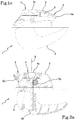
figure 1 a is a view of a locking device for a roof box in a first position; -
figure 1b is a view of a locking device for a roof boxes in a second position; -
figure 1c is a view of a locking device for a roof boxes in a third position; -
figure 2a is a view in section of a locking device for a roof box in a first position; -
figure 2b is a view in section of a locking device for a roof box in a first position; -
figure 2c is a view in section of a locking device for a roof box in a first position; -
figure 3 is a view in section of a component of locking device for a roof box. - In the accompanying figures,
reference numeral 1 denotes in its entirety a locking device for roof boxes according to the present invention. - The
locking device 1 of the present invention is particularly adapted to constrain a roof box to a roof of a motor car. - In particular, the
locking device 1 comprises: afirst locking element 2, asecond locking element 3 and aclamping device 4. - A
first locking element 2 is adapted to be housed on a resting surface and is configured to be couplable to thesecond locking element 3. - The
second locking element 3 is configured to be constrainable to thefirst locking element 2 so as to be movable with respect to it along a locking axis X perpendicular to the resting surface. - The
second locking element 3 is preferably substantially hook shaped which is adapted to engage a bar at the bottom, for example of a vehicle, such as a motor car, on which thelocking device 1 can be installed. - The
clamping device 4 is configured to vary the relative distance between the first and thesecond locking element - In other words, the
clamping device 4 enables mediating the movement of thesecond locking element 3 with respect to thefirst locking element 2, so as to enable, for example, locking a bar between them, thus constraining thelocking device 1. - In particular, the
clamping device 5 comprises afirst end 4a positioned above thefirst locking element 2 and asecond end 4b constrained in a lower portion of thesecond locking element 3. - For the purposes of the present description the terms at the bottom and above are used in reference to a normal use configuration of the
locking device 1 in which the first locking element is arranged on the resting surface, which represents the origin of the reference system with respect to which the terms above and at the bottom are defined. - The term above means that the
first end 4a is positioned superiorly to thefirst locking element 2 when thefirst locking element 2 is housed on the resting surface. - In a preferred embodiment, the
first end 4a of theclamping device 4 is a screwing head and thefirst locking element 2 has a countershaped upper portion adapted to at least partially receive a lower portion of the screwing head. - In detail, and still in accordance with the above-cited preferred embodiment, the screwing head has an internally threaded seat and the
second end 4b of theclamping device 4 is a threaded body adapted to engage said internally threaded seat and to slide inside it according to a screwing/unscrewing movement along the locking axis X. - With the purpose of guaranteeing a correct hold of the
clamping device 4, and preventing it from loosening, thefirst locking element 2 is elastically deformable and comprises anexpansion device 5 configured to expand thefirst locking element 2 increasing the dimensions thereof along the locking axis X. - In particular, the expansion of the
first locking element 2 causes a raising, along the locking axis X and with respect to the resting surface on which thefirst locking element 2 is housed, of thefirst end 4a of theclamping device 4. - The
first end 4a draws while moving thesecond end 4b and consequently thesecond locking element 3 to which it is constrained, thus further nearing it to the resting surface, reducing the distance with respect to thefirst locking element 2 and improving the clamping, defining an extra clamping stroke. - In greater detail, in use the
clamping device 4 is activated to promote a nearing of thesecond locking element 3 to thefirst locking element 2, in such a way as to clamp a bar of a vehicle between the twolocking elements - However, even after having reached a locked condition in which the force of an user is no longer sufficient to promote a further nearing of the two
locking elements figures 1b and2b , it is not possible to ensure that theclamping device 4 is not loosened, thus generating the risk of a detachment of thelocking device 1 from the bar to which it is applied. - With the aim of guaranteeing a correct hold of the device, the
expansion device 5 is activated in such a way as to promote a further nearing of thesecond locking element 3 to the resting surface and thus to thefirst locking element 2, substantially providing the extra clamping stroke which reinforces the clamping and guarantees the hold even for long periods of use. - The device according to the present invention does not therefore require the use of other components than the
locking device 1 to prevent loosening thereof. - In the same way, the presence of the
expansion device 5 guarantees that the provided extra stroke is stable, as it does not allow thefirst locking element 2 to return into the initial condition thereof, in which a loosening of the locking device might be generated over a lengthy period. - In a preferred embodiment, illustrated in the appended figures, the
expansion device 5 comprises ahandle 5a and acam 5b, associated to thehandle 5a. - The cam is adapted to rotate between an opening position in which the
first locking element 2 is not expanded and a clamping position in which thefirst locking element 2 is expanded. - The
handle 5a is configured to mediate the rotation of thecam 5b from the opening position to the clamping position. - In particular, the term cam means, in its entirety, an element having a body with a variable diameter defining a greater diameter, coinciding with the largest diameter definable by the body of the
cam 5b, and a lesser diameter coinciding to the minimum diameter definable by the body of thecam 5b. - The
cam 5b is positioned internally of thefirst locking element 2 and is interposed between a lower surface thereof and an upper surface thereof and in contact therewith. - In the opening position the smaller diameter of the
cam 5b is positioned substantially parallel to the locking axis "X", as shown in detail infigure 2a , thus defining a minimum volume of thecam 5b internally of thefirst locking element 2 along the locking axis X. - In the clamping position the larger diameter of the
cam 5b is positioned substantially parallel to the locking axis "X", as illustrated in detail infigure 2c , thus defining a maximum volume of thecam 5b internally of thefirst locking element 2 along the locking axis X, thus causing an expansion thereof along the axis. -
Figure 3 in particular illustrates thefirst locking element 2 in the opening position (broken line) and in the clamping position (unbroken line), and it can be observed that the passage from one position to the other leads to an increase in the volume of thefirst locking element 2 along the locking axis "X". - The
locking device 1 according to the present invention can further comprise a slot "A" arranged above thehandle 5a of theexpansion device 5, when thecam 5b is in the clamping position, along the locking axis X. The slot "A" is configured for the insertion of a locking body, preferably a rope, adapted to prevent the movement of thehandle 5a. - The locking body can advantageously be a rope, alike to those which are normally used in the sector of roof boxes for vehicles, for securing the load and preventing movement thereof during transport.
- In other words, the presence of the slot "A" enables adding a further degree of safety and stability to the
locking device 1. - The present invention further relates to a roof box for vehicles, for example motor cars, which comprises a box and a plurality of
locking devices 1 according to what is described in the foregoing. - The roof box has a base defining the resting surface on which the
locking devices 1 can be installed. - In particular, the base has a plurality of through seats each of which is adapted to house the
clamping device 4 of arespective locking device 1. In other words, once thelocking device 1 has been applied to the box thefirst coupling element 2 will be stably constrained to the base of the box above the resting surface. - On the contrary, the
second coupling element 3 is movable with respect to the base of the box and positioned below the resting surface. - The
clamping device 4 instead passes through the resting surface and through a through-seat afforded in the base of the box, constraining thefirst locking element 2 and thesecond locking element 3 to one another. - In a preferred embodiment, the roof box comprises two pairs of locking
devices 1, each pair being adapted to stably constrain the roof box to a respective bar of a vehicle. - With the aims of accelerating the constraining operations of the roof box to the vehicle the
locking devices 1 can be made in such a way that thefirst locking elements 2 of each lockingdevice 1 of each pair are respectively coupled so that an expansion of thefirst locking element 2 of alocking device 1 causes the expansion of thefirst locking element 2 of theother locking device 1 of the pair. - In the same way all the
locking devices 1 can be made in such a way that thefirst locking elements 2 of each lockingdevice 1 of the plurality of lockingdevices 1 are respectively coupled so that an expansion of thefirst locking element 2 of alocking device 1 also causes the expansion of thefirst locking element 2 of everyother locking device 1 of the plurality. - For example, it is possible to realise an
expansion device 5 which has asingle handle 5a configured to operate contemporaneously on a plurality ofcams 5b belonging to different locking devices, so as to accelerate and make more efficient the activation of thelocking device 5. - The
locking device 1 for a roof box according to the present invention advantageously enables obviating the above-described drawbacks and problems present in the prior art devices. - In particular, the special conformation of the
first locking element 1 and the presence of theexpansion device 5 enable providing an efficient and secure system for guaranteeing the hold of theclamping device 1, even for long periods of time. - The
locking device 1 is also advantageously impervious to the presence of vibrations during the motion of the vehicle, as the expansion of thefirst locking element 1 constrains theclamping device 5, preventing it from loosening.
Claims (13)
- A locking device (1) for a roof box comprising:- a first locking element (2) adapted to be housed on a resting surface;- a second locking element (3) that can be constrained to the first locking element (2) and movable with respect to it along a locking axis (X) perpendicular to said resting surface;- a clamping device (4) configured to vary a relative distance between said first and second locking element (3) performing a clamping stroke of the second locking element (3) and having a first end (4a) positioned above the first locking element (2) and a second end (4b) constrained in a lower portion of the second locking element (3);
characterised in that said first locking element (2) is elastically deformable and comprises an expansion device (5) configured to expand said first locking element (2) increasing its dimensions along said locking axis (X) to obtain an extra clamping stroke. - The device according to claim 1 wherein said expansion device (5) comprises a handle (5a) and a cam (5b), associated with said handle (5a), adapted to rotate between an opening position in which the first locking element (2) is not expanded and a clamping position in which the first locking element (2) is expanded, said handle (5a) being configured to mediate the rotation of said cam (5b) from the open position to the clamping position.
- The device according to claim 2 wherein the first locking element (2) has an internal cavity delimited by a lower surface and an upper surface and said cam (5b) is arranged internally to the cavity and interposed between the lower surface and the upper surface in contact therewith.
- The device according to claim 2 or 3 wherein the first locking device (2) has a slot (A) arranged above the handle (5a) of the expansion device (5), when the cam (5b) is in the clamping position, along the locking axis (X) and configured for the insertion of a locking body, preferably a rope, adapted to prevent the movement of the handle (5a).
- The device according to one or more of the preceding claims wherein the first end (4a) of the clamping device (4) is a screwing head and the first locking element (2) has a countershaped upper portion adapted to receive at least partially a lower portion of said screwing head.
- The device according to claim 5 wherein the screwing head has an internally threaded seat and the second end (4b) of the clamping device (4) is a threaded body adapted to engage said internally threaded seat and to slide inside it according to a screwing/unscrewing movement along the locking axis (X).
- The device according to one or more of the preceding claims wherein the second expansion element is substantially hook shaped adapted to engage a bar at the bottom.
- A roof box for vehicles comprising:- a box having a base defining a resting surface;- a plurality of locking devices (1) in accordance with one or more of the preceding claims 1-7;
said base having a plurality of through seats each adapted to house the clamping device (4) of a respective locking device. - The roof box according to claim 8 wherein the first coupling element is stably constrained to the base of the box above the resting surface.
- The roof box according to claim 8 or 9 wherein the second coupling element is movable with respect to the base of the box and positioned below the resting surface.
- The roof box according to one or more of the preceding claims 8-10 comprising two pairs of locking devices, each pair being adapted to stably constrain the roof box to a respective bar of a vehicle.
- The roof box according to claim 11 wherein the locking devices (1) of each pair are respectively coupled so that an expansion of the first locking element (2) of a locking device (1) causes the expansion of the first locking element (2) of the other locking device (1) of the pair.
- The roof box according to one or more of the preceding claims wherein all the locking devices (1) are respectively coupled so that an expansion of the first locking element (2) of a locking device (1) causes the expansion of the first locking element (2) of each other locking device (1).
Applications Claiming Priority (1)
| Application Number | Priority Date | Filing Date | Title |
|---|---|---|---|
| IT102017000082774A IT201700082774A1 (en) | 2017-07-20 | 2017-07-20 | Locking device for roof box |
Publications (2)
| Publication Number | Publication Date |
|---|---|
| EP3431340A1 EP3431340A1 (en) | 2019-01-23 |
| EP3431340B1 true EP3431340B1 (en) | 2020-02-12 |
Family
ID=60990950
Family Applications (1)
| Application Number | Title | Priority Date | Filing Date |
|---|---|---|---|
| EP18183856.6A Active EP3431340B1 (en) | 2017-07-20 | 2018-07-17 | A locking device for a roof box |
Country Status (2)
| Country | Link |
|---|---|
| EP (1) | EP3431340B1 (en) |
| IT (1) | IT201700082774A1 (en) |
Family Cites Families (3)
| Publication number | Priority date | Publication date | Assignee | Title |
|---|---|---|---|---|
| DE4334331A1 (en) * | 1993-10-08 | 1995-04-13 | Happich Gmbh Gebr | Cross beams for roof loads on a motor vehicle equipped with a roof rail |
| US5845828A (en) * | 1996-01-12 | 1998-12-08 | Yakima Products | Tower assembly for mounting a crossbar to a vehicle roof rack |
| US6918521B2 (en) * | 2003-01-28 | 2005-07-19 | Watermark Paddlesports, Inc. | Car top carrier with quick release clamping device |
-
2017
- 2017-07-20 IT IT102017000082774A patent/IT201700082774A1/en unknown
-
2018
- 2018-07-17 EP EP18183856.6A patent/EP3431340B1/en active Active
Non-Patent Citations (1)
| Title |
|---|
| None * |
Also Published As
| Publication number | Publication date |
|---|---|
| IT201700082774A1 (en) | 2019-01-20 |
| EP3431340A1 (en) | 2019-01-23 |
Similar Documents
| Publication | Publication Date | Title |
|---|---|---|
| EP1596111B1 (en) | Clamp device for a pipe | |
| US9604685B2 (en) | Transport device for fixing to a vehicle frame element | |
| EP1086285B1 (en) | Locking device and bonnet lock for a vehicle comprising such a locking device | |
| EP3309006B1 (en) | Sliding armrest for vehicle | |
| US5104018A (en) | Article carrying system | |
| EP2381553A2 (en) | Clamp | |
| US9360033B2 (en) | Device for detachable fastening of an assembly part | |
| US20180015852A1 (en) | Locking device for foldable structure | |
| JPH09226501A (en) | Car occupant restraint system | |
| EP3431340A1 (en) | A locking device for a roof box | |
| US5491990A (en) | Steering wheel disabling device | |
| US11358530B2 (en) | Apparatus for receiving an object in a motor vehicle | |
| WO1990010557A1 (en) | An apparatus in load carriers | |
| EP1733921B1 (en) | Cargo securing device | |
| CN108501822B (en) | Vehicle interior and exterior cargo management system | |
| WO2020165719A1 (en) | Vehicle door with an emergency opening system | |
| CN105358780A (en) | Motor vehicle lock with fixing mechanism | |
| US1393022A (en) | Automobile-locking device | |
| JP4733118B2 (en) | Method for protecting vehicle parts and parts pivotable relative to an opening in case of a collision | |
| WO2004066773A8 (en) | Separating lock comprising a triggering device | |
| JP2008502528A5 (en) | ||
| WO2019096938A1 (en) | Door handle assembly for a motor vehicle | |
| US9475460B2 (en) | Gear lever locking device | |
| CN120051399A (en) | Device for hooking objects in a vehicle | |
| KR0117359Y1 (en) | Anti-theft safety nob for automotive vehicles |
Legal Events
| Date | Code | Title | Description |
|---|---|---|---|
| PUAI | Public reference made under article 153(3) epc to a published international application that has entered the european phase |
Free format text: ORIGINAL CODE: 0009012 |
|
| STAA | Information on the status of an ep patent application or granted ep patent |
Free format text: STATUS: THE APPLICATION HAS BEEN PUBLISHED |
|
| AK | Designated contracting states |
Kind code of ref document: A1 Designated state(s): AL AT BE BG CH CY CZ DE DK EE ES FI FR GB GR HR HU IE IS IT LI LT LU LV MC MK MT NL NO PL PT RO RS SE SI SK SM TR |
|
| AX | Request for extension of the european patent |
Extension state: BA ME |
|
| STAA | Information on the status of an ep patent application or granted ep patent |
Free format text: STATUS: REQUEST FOR EXAMINATION WAS MADE |
|
| 17P | Request for examination filed |
Effective date: 20190626 |
|
| RBV | Designated contracting states (corrected) |
Designated state(s): AL AT BE BG CH CY CZ DE DK EE ES FI FR GB GR HR HU IE IS IT LI LT LU LV MC MK MT NL NO PL PT RO RS SE SI SK SM TR |
|
| GRAP | Despatch of communication of intention to grant a patent |
Free format text: ORIGINAL CODE: EPIDOSNIGR1 |
|
| STAA | Information on the status of an ep patent application or granted ep patent |
Free format text: STATUS: GRANT OF PATENT IS INTENDED |
|
| INTG | Intention to grant announced |
Effective date: 20190909 |
|
| GRAS | Grant fee paid |
Free format text: ORIGINAL CODE: EPIDOSNIGR3 |
|
| GRAA | (expected) grant |
Free format text: ORIGINAL CODE: 0009210 |
|
| STAA | Information on the status of an ep patent application or granted ep patent |
Free format text: STATUS: THE PATENT HAS BEEN GRANTED |
|
| AK | Designated contracting states |
Kind code of ref document: B1 Designated state(s): AL AT BE BG CH CY CZ DE DK EE ES FI FR GB GR HR HU IE IS IT LI LT LU LV MC MK MT NL NO PL PT RO RS SE SI SK SM TR |
|
| REG | Reference to a national code |
Ref country code: GB Ref legal event code: FG4D |
|
| REG | Reference to a national code |
Ref country code: CH Ref legal event code: EP |
|
| REG | Reference to a national code |
Ref country code: AT Ref legal event code: REF Ref document number: 1231678 Country of ref document: AT Kind code of ref document: T Effective date: 20200215 |
|
| REG | Reference to a national code |
Ref country code: IE Ref legal event code: FG4D |
|
| REG | Reference to a national code |
Ref country code: DE Ref legal event code: R096 Ref document number: 602018002387 Country of ref document: DE |
|
| PG25 | Lapsed in a contracting state [announced via postgrant information from national office to epo] |
Ref country code: RS Free format text: LAPSE BECAUSE OF FAILURE TO SUBMIT A TRANSLATION OF THE DESCRIPTION OR TO PAY THE FEE WITHIN THE PRESCRIBED TIME-LIMIT Effective date: 20200212 Ref country code: FI Free format text: LAPSE BECAUSE OF FAILURE TO SUBMIT A TRANSLATION OF THE DESCRIPTION OR TO PAY THE FEE WITHIN THE PRESCRIBED TIME-LIMIT Effective date: 20200212 Ref country code: NO Free format text: LAPSE BECAUSE OF FAILURE TO SUBMIT A TRANSLATION OF THE DESCRIPTION OR TO PAY THE FEE WITHIN THE PRESCRIBED TIME-LIMIT Effective date: 20200512 |
|
| REG | Reference to a national code |
Ref country code: LT Ref legal event code: MG4D |
|
| REG | Reference to a national code |
Ref country code: NL Ref legal event code: MP Effective date: 20200212 |
|
| PG25 | Lapsed in a contracting state [announced via postgrant information from national office to epo] |
Ref country code: IS Free format text: LAPSE BECAUSE OF FAILURE TO SUBMIT A TRANSLATION OF THE DESCRIPTION OR TO PAY THE FEE WITHIN THE PRESCRIBED TIME-LIMIT Effective date: 20200612 Ref country code: LV Free format text: LAPSE BECAUSE OF FAILURE TO SUBMIT A TRANSLATION OF THE DESCRIPTION OR TO PAY THE FEE WITHIN THE PRESCRIBED TIME-LIMIT Effective date: 20200212 Ref country code: SE Free format text: LAPSE BECAUSE OF FAILURE TO SUBMIT A TRANSLATION OF THE DESCRIPTION OR TO PAY THE FEE WITHIN THE PRESCRIBED TIME-LIMIT Effective date: 20200212 Ref country code: BG Free format text: LAPSE BECAUSE OF FAILURE TO SUBMIT A TRANSLATION OF THE DESCRIPTION OR TO PAY THE FEE WITHIN THE PRESCRIBED TIME-LIMIT Effective date: 20200512 Ref country code: HR Free format text: LAPSE BECAUSE OF FAILURE TO SUBMIT A TRANSLATION OF THE DESCRIPTION OR TO PAY THE FEE WITHIN THE PRESCRIBED TIME-LIMIT Effective date: 20200212 Ref country code: GR Free format text: LAPSE BECAUSE OF FAILURE TO SUBMIT A TRANSLATION OF THE DESCRIPTION OR TO PAY THE FEE WITHIN THE PRESCRIBED TIME-LIMIT Effective date: 20200513 |
|
| PG25 | Lapsed in a contracting state [announced via postgrant information from national office to epo] |
Ref country code: NL Free format text: LAPSE BECAUSE OF FAILURE TO SUBMIT A TRANSLATION OF THE DESCRIPTION OR TO PAY THE FEE WITHIN THE PRESCRIBED TIME-LIMIT Effective date: 20200212 |
|
| PG25 | Lapsed in a contracting state [announced via postgrant information from national office to epo] |
Ref country code: EE Free format text: LAPSE BECAUSE OF FAILURE TO SUBMIT A TRANSLATION OF THE DESCRIPTION OR TO PAY THE FEE WITHIN THE PRESCRIBED TIME-LIMIT Effective date: 20200212 Ref country code: LT Free format text: LAPSE BECAUSE OF FAILURE TO SUBMIT A TRANSLATION OF THE DESCRIPTION OR TO PAY THE FEE WITHIN THE PRESCRIBED TIME-LIMIT Effective date: 20200212 Ref country code: DK Free format text: LAPSE BECAUSE OF FAILURE TO SUBMIT A TRANSLATION OF THE DESCRIPTION OR TO PAY THE FEE WITHIN THE PRESCRIBED TIME-LIMIT Effective date: 20200212 Ref country code: PT Free format text: LAPSE BECAUSE OF FAILURE TO SUBMIT A TRANSLATION OF THE DESCRIPTION OR TO PAY THE FEE WITHIN THE PRESCRIBED TIME-LIMIT Effective date: 20200705 Ref country code: SM Free format text: LAPSE BECAUSE OF FAILURE TO SUBMIT A TRANSLATION OF THE DESCRIPTION OR TO PAY THE FEE WITHIN THE PRESCRIBED TIME-LIMIT Effective date: 20200212 Ref country code: SK Free format text: LAPSE BECAUSE OF FAILURE TO SUBMIT A TRANSLATION OF THE DESCRIPTION OR TO PAY THE FEE WITHIN THE PRESCRIBED TIME-LIMIT Effective date: 20200212 Ref country code: ES Free format text: LAPSE BECAUSE OF FAILURE TO SUBMIT A TRANSLATION OF THE DESCRIPTION OR TO PAY THE FEE WITHIN THE PRESCRIBED TIME-LIMIT Effective date: 20200212 Ref country code: CZ Free format text: LAPSE BECAUSE OF FAILURE TO SUBMIT A TRANSLATION OF THE DESCRIPTION OR TO PAY THE FEE WITHIN THE PRESCRIBED TIME-LIMIT Effective date: 20200212 Ref country code: RO Free format text: LAPSE BECAUSE OF FAILURE TO SUBMIT A TRANSLATION OF THE DESCRIPTION OR TO PAY THE FEE WITHIN THE PRESCRIBED TIME-LIMIT Effective date: 20200212 |
|
| REG | Reference to a national code |
Ref country code: DE Ref legal event code: R097 Ref document number: 602018002387 Country of ref document: DE |
|
| REG | Reference to a national code |
Ref country code: AT Ref legal event code: MK05 Ref document number: 1231678 Country of ref document: AT Kind code of ref document: T Effective date: 20200212 |
|
| PLBE | No opposition filed within time limit |
Free format text: ORIGINAL CODE: 0009261 |
|
| STAA | Information on the status of an ep patent application or granted ep patent |
Free format text: STATUS: NO OPPOSITION FILED WITHIN TIME LIMIT |
|
| 26N | No opposition filed |
Effective date: 20201113 |
|
| PG25 | Lapsed in a contracting state [announced via postgrant information from national office to epo] |
Ref country code: IT Free format text: LAPSE BECAUSE OF FAILURE TO SUBMIT A TRANSLATION OF THE DESCRIPTION OR TO PAY THE FEE WITHIN THE PRESCRIBED TIME-LIMIT Effective date: 20200212 Ref country code: AT Free format text: LAPSE BECAUSE OF FAILURE TO SUBMIT A TRANSLATION OF THE DESCRIPTION OR TO PAY THE FEE WITHIN THE PRESCRIBED TIME-LIMIT Effective date: 20200212 |
|
| PG25 | Lapsed in a contracting state [announced via postgrant information from national office to epo] |
Ref country code: SI Free format text: LAPSE BECAUSE OF FAILURE TO SUBMIT A TRANSLATION OF THE DESCRIPTION OR TO PAY THE FEE WITHIN THE PRESCRIBED TIME-LIMIT Effective date: 20200212 Ref country code: PL Free format text: LAPSE BECAUSE OF FAILURE TO SUBMIT A TRANSLATION OF THE DESCRIPTION OR TO PAY THE FEE WITHIN THE PRESCRIBED TIME-LIMIT Effective date: 20200212 Ref country code: MC Free format text: LAPSE BECAUSE OF FAILURE TO SUBMIT A TRANSLATION OF THE DESCRIPTION OR TO PAY THE FEE WITHIN THE PRESCRIBED TIME-LIMIT Effective date: 20200212 |
|
| REG | Reference to a national code |
Ref country code: BE Ref legal event code: MM Effective date: 20200731 |
|
| PG25 | Lapsed in a contracting state [announced via postgrant information from national office to epo] |
Ref country code: LU Free format text: LAPSE BECAUSE OF NON-PAYMENT OF DUE FEES Effective date: 20200717 |
|
| PG25 | Lapsed in a contracting state [announced via postgrant information from national office to epo] |
Ref country code: BE Free format text: LAPSE BECAUSE OF NON-PAYMENT OF DUE FEES Effective date: 20200731 |
|
| PG25 | Lapsed in a contracting state [announced via postgrant information from national office to epo] |
Ref country code: IE Free format text: LAPSE BECAUSE OF NON-PAYMENT OF DUE FEES Effective date: 20200717 |
|
| REG | Reference to a national code |
Ref country code: CH Ref legal event code: PL |
|
| PG25 | Lapsed in a contracting state [announced via postgrant information from national office to epo] |
Ref country code: LI Free format text: LAPSE BECAUSE OF NON-PAYMENT OF DUE FEES Effective date: 20210731 Ref country code: CH Free format text: LAPSE BECAUSE OF NON-PAYMENT OF DUE FEES Effective date: 20210731 |
|
| PG25 | Lapsed in a contracting state [announced via postgrant information from national office to epo] |
Ref country code: TR Free format text: LAPSE BECAUSE OF FAILURE TO SUBMIT A TRANSLATION OF THE DESCRIPTION OR TO PAY THE FEE WITHIN THE PRESCRIBED TIME-LIMIT Effective date: 20200212 Ref country code: MT Free format text: LAPSE BECAUSE OF FAILURE TO SUBMIT A TRANSLATION OF THE DESCRIPTION OR TO PAY THE FEE WITHIN THE PRESCRIBED TIME-LIMIT Effective date: 20200212 Ref country code: CY Free format text: LAPSE BECAUSE OF FAILURE TO SUBMIT A TRANSLATION OF THE DESCRIPTION OR TO PAY THE FEE WITHIN THE PRESCRIBED TIME-LIMIT Effective date: 20200212 |
|
| PG25 | Lapsed in a contracting state [announced via postgrant information from national office to epo] |
Ref country code: MK Free format text: LAPSE BECAUSE OF FAILURE TO SUBMIT A TRANSLATION OF THE DESCRIPTION OR TO PAY THE FEE WITHIN THE PRESCRIBED TIME-LIMIT Effective date: 20200212 Ref country code: AL Free format text: LAPSE BECAUSE OF FAILURE TO SUBMIT A TRANSLATION OF THE DESCRIPTION OR TO PAY THE FEE WITHIN THE PRESCRIBED TIME-LIMIT Effective date: 20200212 |
|
| PGFP | Annual fee paid to national office [announced via postgrant information from national office to epo] |
Ref country code: DE Payment date: 20250728 Year of fee payment: 8 |
|
| PGFP | Annual fee paid to national office [announced via postgrant information from national office to epo] |
Ref country code: GB Payment date: 20250722 Year of fee payment: 8 |
|
| PGFP | Annual fee paid to national office [announced via postgrant information from national office to epo] |
Ref country code: FR Payment date: 20250725 Year of fee payment: 8 |