EP3431218A1 - Friction welding method - Google Patents
Friction welding method Download PDFInfo
- Publication number
- EP3431218A1 EP3431218A1 EP18182080.4A EP18182080A EP3431218A1 EP 3431218 A1 EP3431218 A1 EP 3431218A1 EP 18182080 A EP18182080 A EP 18182080A EP 3431218 A1 EP3431218 A1 EP 3431218A1
- Authority
- EP
- European Patent Office
- Prior art keywords
- axial force
- spike
- oscillation
- rotor
- seconds
- Prior art date
- Legal status (The legal status is an assumption and is not a legal conclusion. Google has not performed a legal analysis and makes no representation as to the accuracy of the status listed.)
- Granted
Links
Images

Classifications
-
- B—PERFORMING OPERATIONS; TRANSPORTING
- B23—MACHINE TOOLS; METAL-WORKING NOT OTHERWISE PROVIDED FOR
- B23K—SOLDERING OR UNSOLDERING; WELDING; CLADDING OR PLATING BY SOLDERING OR WELDING; CUTTING BY APPLYING HEAT LOCALLY, e.g. FLAME CUTTING; WORKING BY LASER BEAM
- B23K20/00—Non-electric welding by applying impact or other pressure, with or without the application of heat, e.g. cladding or plating
- B23K20/12—Non-electric welding by applying impact or other pressure, with or without the application of heat, e.g. cladding or plating the heat being generated by friction; Friction welding
- B23K20/1205—Non-electric welding by applying impact or other pressure, with or without the application of heat, e.g. cladding or plating the heat being generated by friction; Friction welding using translation movement
-
- B—PERFORMING OPERATIONS; TRANSPORTING
- B23—MACHINE TOOLS; METAL-WORKING NOT OTHERWISE PROVIDED FOR
- B23K—SOLDERING OR UNSOLDERING; WELDING; CLADDING OR PLATING BY SOLDERING OR WELDING; CUTTING BY APPLYING HEAT LOCALLY, e.g. FLAME CUTTING; WORKING BY LASER BEAM
- B23K20/00—Non-electric welding by applying impact or other pressure, with or without the application of heat, e.g. cladding or plating
- B23K20/12—Non-electric welding by applying impact or other pressure, with or without the application of heat, e.g. cladding or plating the heat being generated by friction; Friction welding
- B23K20/122—Non-electric welding by applying impact or other pressure, with or without the application of heat, e.g. cladding or plating the heat being generated by friction; Friction welding using a non-consumable tool, e.g. friction stir welding
-
- B—PERFORMING OPERATIONS; TRANSPORTING
- B23—MACHINE TOOLS; METAL-WORKING NOT OTHERWISE PROVIDED FOR
- B23K—SOLDERING OR UNSOLDERING; WELDING; CLADDING OR PLATING BY SOLDERING OR WELDING; CUTTING BY APPLYING HEAT LOCALLY, e.g. FLAME CUTTING; WORKING BY LASER BEAM
- B23K20/00—Non-electric welding by applying impact or other pressure, with or without the application of heat, e.g. cladding or plating
- B23K20/12—Non-electric welding by applying impact or other pressure, with or without the application of heat, e.g. cladding or plating the heat being generated by friction; Friction welding
- B23K20/121—Control circuits therefor
-
- B—PERFORMING OPERATIONS; TRANSPORTING
- B23—MACHINE TOOLS; METAL-WORKING NOT OTHERWISE PROVIDED FOR
- B23K—SOLDERING OR UNSOLDERING; WELDING; CLADDING OR PLATING BY SOLDERING OR WELDING; CUTTING BY APPLYING HEAT LOCALLY, e.g. FLAME CUTTING; WORKING BY LASER BEAM
- B23K20/00—Non-electric welding by applying impact or other pressure, with or without the application of heat, e.g. cladding or plating
- B23K20/12—Non-electric welding by applying impact or other pressure, with or without the application of heat, e.g. cladding or plating the heat being generated by friction; Friction welding
- B23K20/122—Non-electric welding by applying impact or other pressure, with or without the application of heat, e.g. cladding or plating the heat being generated by friction; Friction welding using a non-consumable tool, e.g. friction stir welding
- B23K20/123—Controlling or monitoring the welding process
-
- B—PERFORMING OPERATIONS; TRANSPORTING
- B23—MACHINE TOOLS; METAL-WORKING NOT OTHERWISE PROVIDED FOR
- B23K—SOLDERING OR UNSOLDERING; WELDING; CLADDING OR PLATING BY SOLDERING OR WELDING; CUTTING BY APPLYING HEAT LOCALLY, e.g. FLAME CUTTING; WORKING BY LASER BEAM
- B23K20/00—Non-electric welding by applying impact or other pressure, with or without the application of heat, e.g. cladding or plating
- B23K20/22—Non-electric welding by applying impact or other pressure, with or without the application of heat, e.g. cladding or plating taking account of the properties of the materials to be welded
-
- B—PERFORMING OPERATIONS; TRANSPORTING
- B23—MACHINE TOOLS; METAL-WORKING NOT OTHERWISE PROVIDED FOR
- B23K—SOLDERING OR UNSOLDERING; WELDING; CLADDING OR PLATING BY SOLDERING OR WELDING; CUTTING BY APPLYING HEAT LOCALLY, e.g. FLAME CUTTING; WORKING BY LASER BEAM
- B23K20/00—Non-electric welding by applying impact or other pressure, with or without the application of heat, e.g. cladding or plating
- B23K20/26—Auxiliary equipment
-
- B—PERFORMING OPERATIONS; TRANSPORTING
- B23—MACHINE TOOLS; METAL-WORKING NOT OTHERWISE PROVIDED FOR
- B23K—SOLDERING OR UNSOLDERING; WELDING; CLADDING OR PLATING BY SOLDERING OR WELDING; CUTTING BY APPLYING HEAT LOCALLY, e.g. FLAME CUTTING; WORKING BY LASER BEAM
- B23K2101/00—Articles made by soldering, welding or cutting
- B23K2101/001—Turbines
-
- B—PERFORMING OPERATIONS; TRANSPORTING
- B23—MACHINE TOOLS; METAL-WORKING NOT OTHERWISE PROVIDED FOR
- B23K—SOLDERING OR UNSOLDERING; WELDING; CLADDING OR PLATING BY SOLDERING OR WELDING; CUTTING BY APPLYING HEAT LOCALLY, e.g. FLAME CUTTING; WORKING BY LASER BEAM
- B23K2103/00—Materials to be soldered, welded or cut
- B23K2103/18—Dissimilar materials
Definitions
- This invention relates generally to welding, and more particularly to methods for friction welding.
- Friction welding of components such as gas turbine engine blades to rotors is known in the manufacture or repair of an integrally bladed disk, sometimes known as a BLISK.
- An integrally bladed disk is a disk or wheel on the periphery of which there is attached or carried a multiplicity of blades forming a monolithic structure or component. This same technique may also be used to attach a blade to a multi-stage monolithic drum rotor of a gas turbine engine.
- the blades are attached to a disk or wheel by interlocking dovetail attachment methods.
- integrally bladed disks and drums the blades are either formed and machined integrally with the disk or drum or are welded or otherwise bonded thereto.
- the components to be bonded together are linearly or translationally rubbed one against the other with a reciprocating translational motion so that at their interface sufficient heat is generated by friction to effect the weld. Then, an axial welding force is applied to urge the components with a steady force to promote a better weld.
- friction welding machine controls are tuned to prevent the weld from under or overshooting desired set points during conditioning, burn off, and forge phases of operation. While this tuning provides a uniform upset rate and predictable total upset during a weld, it can also restrict rate of application and amount of forge axial force. As a result, the horizontal displacement rate and compressive forces exerted by the machine can be reduced.
- a friction welding method includes: applying axial force to first and second metallic components so as to force the components against each other at an interface therebetween, while oscillating the two components relative to each other in a cyclic motion, so as to generate friction and heat at the interface; rapidly stopping the cyclic motion; and applying a spike in the axial force to complete a weld between the first and second components.
- a method of friction welding a blade to a rotor includes: applying axial force to press an airfoil stub of the blade against a rotor stub of the rotor at an interface therebetween; oscillating the blade in a cyclic motion relative to the rotor stub to generate friction and heat at the interface; and rapidly stopping the oscillation and applying a spike in axial force to complete a weld between the blade and the rotor.
- the present invention may be used for any irrotational movement for friction welding which may take either of two forms. It may be linear in which case the component is caused to undergo a substantially linear or translational reciprocating motion during the friction heating phase, or it may be an orbital movement in which the moving component follows a closed loop path.
- FIG. 1 illustrates a part of a prior art friction bonding machine 10 as described in United States Patent 5,813,593 , the disclosure of which is herein incorporated by reference.
- the machine 10 has a headstock 11.
- the headstock 11 has mounted to it an apparatus 12 for friction welding of a first component exemplified by a gas turbine engine blade 14 to a second component exemplified by a gas turbine engine rotor 16 in accordance with an exemplary embodiment of the present invention.
- the blade 14 has an airfoil 15 extending longitudinally between an airfoil tip 13 and an airfoil stub 40 and extending transversely between a leading edge and a trailing edge.
- the airfoil stub 40 has a flat welding surface 41 at its bottom.
- the apparatus 12 includes a holder 18 to hold the blade 14. Axial force is applied to the blade 14 through the holder 18 in a first direction F1 to press the airfoil stub 40 of the blade 14 into contact with a rotor stub 42 on a periphery 44 of the rotor 16. Friction welding involves oscillating motion of the blade 14 and airfoil stub 40.
- FIG. 1 is merely one example of a suitable friction bonding apparatus.
- the present invention includes methods for using a friction bonding apparatus for friction welding of the blade 14 to the rotor stub 42.
- the friction welding process involves pressing two components together in an axial direction with axial force F1 and then oscillating the two components relative to each other to generate friction and heat.
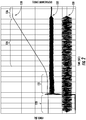
- FIG. 2 illustrates a prior art version of this process.
- the material actually "upsets" 128, that is flows outward from the joint while the two parts come closer together in an axial direction.
- the process operates by oscillating to generate the heat while applying the axial force, then stopping the oscillation with the part in the correct position and continuing to apply the axial force while the forge phase occurs. As the part cools, the weld transforms from a plastic phase back to a solid phase. The excess material extruded from the joint is then machined away.
- the process ends by oscillating over a relatively long period of time 130, for example, about 7 to 8 oscillation cycles while the axial force is held constant 132 (see cone shape formed when oscillation ends and nominally constant force profile).
- the axial force is held constant 132 (see cone shape formed when oscillation ends and nominally constant force profile).
- defects can occur using the prior art method. Such defects may be more prevalent when welding together dissimilar alloys such as Ti-6-4 and Ti-17 due to dissimilar alloys having different properties.
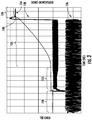
- the method of the present invention uses a "spike forge upset" 134 which has been found to limit the defects associated with prior art methods.
- spike forge upset is defined as a rapid upsetting in the weld area near the end of the weld cycle.
- FIG. 2 which end oscillation over a relatively long period and hold the axial force constant, the method of the present invention stops oscillation very rapidly 136, for example, in one cycle or less (see the squared-off oscillation signal).
- a spike 138 is applied in the axial force, simultaneously or near-simultaneously with stopping the oscillation.
- the spike may include any additional axial force above the baseline axial force.
- the peak axial force may be spiked to a magnitude at least about 1.5 times the baseline axial force.
- the peak axial force may be spiked to a magnitude at least about two times the baseline axial force.
- the peak axial force may be spiked to a magnitude at least about five times the baseline axial force.
- a "spike” refers generally to a rapid increase in the axial force.
- the axial force may be raised (i.e. "spiked") from the baseline level to the peak in less than about 0.2 seconds.
- the axial force may be spiked from the baseline level to the peak in less than about 0.05 seconds. As shown in FIG. 3 , this results in a significant amount of additional material displacement or upset occurring 140 at the very end of the process, in response to the axial force spike. In one example, approximately 15% of the total upset can occur during the spike.
- the method of the present invention adjusts oscillator frequency and amplitude, and axial force parameters to allow frictional heat generated during the conditioning phase 122 and adiabatic heat generated during the burn off phase 124 to soak back into the airfoil and rotor stubs 40, 42 to preheat these areas prior to the forge phase 126.
- This preheating helps promote more rapid axial material flow when the force is increased during the forge phase 126.
- the other parameters that impact spike forge include forge force, forge ramp time, and oscillator ramp time, which all occur during the forge phase of the weld.
- the machine 10 needs to be capable of supplying and maintaining a sufficiently high forge force in a very rapid manner. This is because much of the pre-heat generated by the oscillator movement soaks away rapidly as the oscillation is stopped at the end of the weld.
- the spike forge effect is enhanced by simultaneous or near-simultaneous rapid decay of the oscillation and application of forging force.
- rapid decay refers to stopping the oscillation in a short enough time period that a significant amount of heat does not soak away before the forge force is spiked.
- the oscillation may be stopped in less than about 0.2 seconds. This corresponds to less than 8 cycles where the oscillation frequency is 40 Hz.
- the oscillation may be stopped in less than about 0.025 seconds. This corresponds to less than one cycle where the oscillation frequency is 40 Hz. In another example, the oscillation may be stopped in less than about 0.0125 seconds. This corresponds to less than one-half cycle where the oscillation frequency is 40 Hz.
- the spike may be uncontrolled or open loop, in the sense that the axial force is simply increased to the maximum the machine 10 is capable of providing, without attempting to control.
- the upset is determined by the dynamics of the two parts, the weld preparation, the alloys, etc.
- the spike is helped by taking advantage of the momentum in the machine 10 (i.e., an axial force is already being applied and the force is rapidly increased as the oscillation is stopped).
- the method is highly repeatable. It is generally necessary to add additional material to the parts to accommodate the additional deflection/upset.
- the method described herein has several advantages over the prior art.
- it provides the ability to produce defect-free bi-alloy welds using friction welding.
Landscapes
- Engineering & Computer Science (AREA)
- Mechanical Engineering (AREA)
- Pressure Welding/Diffusion-Bonding (AREA)
Abstract
Description
- This invention relates generally to welding, and more particularly to methods for friction welding.
- Friction welding of components such as gas turbine engine blades to rotors is known in the manufacture or repair of an integrally bladed disk, sometimes known as a BLISK. An integrally bladed disk is a disk or wheel on the periphery of which there is attached or carried a multiplicity of blades forming a monolithic structure or component. This same technique may also be used to attach a blade to a multi-stage monolithic drum rotor of a gas turbine engine. In a conventional rotor assembly, the blades are attached to a disk or wheel by interlocking dovetail attachment methods. In integrally bladed disks and drums the blades are either formed and machined integrally with the disk or drum or are welded or otherwise bonded thereto. The components to be bonded together are linearly or translationally rubbed one against the other with a reciprocating translational motion so that at their interface sufficient heat is generated by friction to effect the weld. Then, an axial welding force is applied to urge the components with a steady force to promote a better weld.
- In the prior art, friction welding machine controls are tuned to prevent the weld from under or overshooting desired set points during conditioning, burn off, and forge phases of operation. While this tuning provides a uniform upset rate and predictable total upset during a weld, it can also restrict rate of application and amount of forge axial force. As a result, the horizontal displacement rate and compressive forces exerted by the machine can be reduced.
- While prior art methods of friction welding work well when the same types of materials are used, testing has shown that some combinations of dissimilar alloys are prone to defects if insufficient displacement rate and/or compressive force are not applied when the oscillator movement is discontinued during the forge phase of the weld. Testing has also shown that frequency and amplitude of the oscillator during the conditioning and burn off phases, and the rate of oscillator decay during the forge phase, can impact upset rate during the forge phase, which can impact weld quality.
- This problem is addressed by a friction welding method using rapid oscillation decay coupled with a spike in axial force to enable bi-alloy welds.
- According to one aspect of the technology described herein, a friction welding method includes: applying axial force to first and second metallic components so as to force the components against each other at an interface therebetween, while oscillating the two components relative to each other in a cyclic motion, so as to generate friction and heat at the interface; rapidly stopping the cyclic motion; and applying a spike in the axial force to complete a weld between the first and second components.
- According to another aspect of the technology described herein, a method of friction welding a blade to a rotor includes: applying axial force to press an airfoil stub of the blade against a rotor stub of the rotor at an interface therebetween; oscillating the blade in a cyclic motion relative to the rotor stub to generate friction and heat at the interface; and rapidly stopping the oscillation and applying a spike in axial force to complete a weld between the blade and the rotor.
- The invention may be best understood by reference to the following description taken in conjunction with the accompanying drawing figures in which:
-
FIG. 1 is a perspective view illustrating a part of a prior art friction bonding machine including an apparatus for friction welding of a gas turbine engine blade component to a gas turbine engine rotor component; -
FIG. 2 is a chart illustrating a prior art friction welding method; and -
FIG. 3 is a chart illustrating a friction welding method conducted in accordance with an aspect of the present invention. - The present invention may be used for any irrotational movement for friction welding which may take either of two forms. It may be linear in which case the component is caused to undergo a substantially linear or translational reciprocating motion during the friction heating phase, or it may be an orbital movement in which the moving component follows a closed loop path.
- Referring now to the drawings in detail wherein identical numerals indicate the same elements throughout the various views,
FIG. 1 illustrates a part of a prior artfriction bonding machine 10 as described in United States Patent5,813,593 , the disclosure of which is herein incorporated by reference. Themachine 10 has aheadstock 11. Theheadstock 11 has mounted to it anapparatus 12 for friction welding of a first component exemplified by a gasturbine engine blade 14 to a second component exemplified by a gasturbine engine rotor 16 in accordance with an exemplary embodiment of the present invention. Theblade 14 has anairfoil 15 extending longitudinally between anairfoil tip 13 and anairfoil stub 40 and extending transversely between a leading edge and a trailing edge. Theairfoil stub 40 has a flat welding surface 41 at its bottom. Theapparatus 12 includes aholder 18 to hold theblade 14. Axial force is applied to theblade 14 through theholder 18 in a first direction F1 to press theairfoil stub 40 of theblade 14 into contact with arotor stub 42 on aperiphery 44 of therotor 16. Friction welding involves oscillating motion of theblade 14 andairfoil stub 40. - It will be understood that the apparatus shown in
FIG. 1 is merely one example of a suitable friction bonding apparatus. The present invention includes methods for using a friction bonding apparatus for friction welding of theblade 14 to therotor stub 42. - The friction welding process involves pressing two components together in an axial direction with axial force F1 and then oscillating the two components relative to each other to generate friction and heat. There are four distinct phases: a
contact phase 120, aconditioning phase 122, a burn-offphase 124, and aforge phase 126.FIG. 2 illustrates a prior art version of this process. During theforge phase 126, the material actually "upsets" 128, that is flows outward from the joint while the two parts come closer together in an axial direction. - Generally, the process operates by oscillating to generate the heat while applying the axial force, then stopping the oscillation with the part in the correct position and continuing to apply the axial force while the forge phase occurs. As the part cools, the weld transforms from a plastic phase back to a solid phase. The excess material extruded from the joint is then machined away.
- In the prior art, during the
forge phase 126, the process ends by oscillating over a relatively long period oftime 130, for example, about 7 to 8 oscillation cycles while the axial force is held constant 132 (see cone shape formed when oscillation ends and nominally constant force profile). In other words, all input parameters are tightly controlled with feedback loops and the axial force applied is the same from start to finish. - Unfortunately, it has been found that defects can occur using the prior art method. Such defects may be more prevalent when welding together dissimilar alloys such as Ti-6-4 and Ti-17 due to dissimilar alloys having different properties.
- As shown in
FIG. 3 , the method of the present invention uses a "spike forge upset" 134 which has been found to limit the defects associated with prior art methods. As used herein, "spike forge upset" is defined as a rapid upsetting in the weld area near the end of the weld cycle. Unlike prior art methods,FIG. 2 , which end oscillation over a relatively long period and hold the axial force constant, the method of the present invention stops oscillation very rapidly 136, for example, in one cycle or less (see the squared-off oscillation signal). During theforge phase 126, a spike 138 (see dramatic increase in amplitude of the force signal) is applied in the axial force, simultaneously or near-simultaneously with stopping the oscillation. The spike may include any additional axial force above the baseline axial force. In one example, the peak axial force may be spiked to a magnitude at least about 1.5 times the baseline axial force. In another example, the peak axial force may be spiked to a magnitude at least about two times the baseline axial force. In another example, the peak axial force may be spiked to a magnitude at least about five times the baseline axial force. As used herein, a "spike" refers generally to a rapid increase in the axial force. In one example, the axial force may be raised (i.e. "spiked") from the baseline level to the peak in less than about 0.2 seconds. In another example, the axial force may be spiked from the baseline level to the peak in less than about 0.05 seconds. As shown inFIG. 3 , this results in a significant amount of additional material displacement or upset occurring 140 at the very end of the process, in response to the axial force spike. In one example, approximately 15% of the total upset can occur during the spike. - According to one aspect, the method of the present invention adjusts oscillator frequency and amplitude, and axial force parameters to allow frictional heat generated during the
conditioning phase 122 and adiabatic heat generated during the burn offphase 124 to soak back into the airfoil androtor stubs forge phase 126. This preheating helps promote more rapid axial material flow when the force is increased during theforge phase 126. The other parameters that impact spike forge include forge force, forge ramp time, and oscillator ramp time, which all occur during the forge phase of the weld. - In addition to setting these parameters, the
machine 10 needs to be capable of supplying and maintaining a sufficiently high forge force in a very rapid manner. This is because much of the pre-heat generated by the oscillator movement soaks away rapidly as the oscillation is stopped at the end of the weld. The spike forge effect is enhanced by simultaneous or near-simultaneous rapid decay of the oscillation and application of forging force. Generally, "rapid decay" as used herein refers to stopping the oscillation in a short enough time period that a significant amount of heat does not soak away before the forge force is spiked. In one example, the oscillation may be stopped in less than about 0.2 seconds. This corresponds to less than 8 cycles where the oscillation frequency is 40 Hz. In another example, the oscillation may be stopped in less than about 0.025 seconds. This corresponds to less than one cycle where the oscillation frequency is 40 Hz. In another example, the oscillation may be stopped in less than about 0.0125 seconds. This corresponds to less than one-half cycle where the oscillation frequency is 40 Hz. - Because the machine's moving details are typically massive and slow to react to the oscillation and axial loads during welding, it can be difficult to accelerate this much mass during the spike forge. However, rapid movement can be achieved by detuning of the pressure system and minimizing moving mass of the tooling. By adjusting the control feedback system to allow the force to initially overshoot the target forge force, rapid weld upsetting can be accomplished.
- By intentionally de-tuning the response of the axial force feedback control, a much faster spike forging event can occur as the weld oscillator is simultaneously discontinued. This de-tuning causes axial force to intentionally overshoot the forge force set-point to produce a much faster axial follow-up during the weld. This rapid axial movement creates more rapid compression in the thermo-mechanically affected zone, and heat affected zones of the weld causing an unusually large amount of weld upset. The spike forge process creates an
upset increase 140 of three to four times compared to prior art methods. - Unlike prior art methods, the spike may be uncontrolled or open loop, in the sense that the axial force is simply increased to the maximum the
machine 10 is capable of providing, without attempting to control. The upset is determined by the dynamics of the two parts, the weld preparation, the alloys, etc. The spike is helped by taking advantage of the momentum in the machine 10 (i.e., an axial force is already being applied and the force is rapidly increased as the oscillation is stopped). The method is highly repeatable. It is generally necessary to add additional material to the parts to accommodate the additional deflection/upset. - The method described herein has several advantages over the prior art. In particular, it provides the ability to produce defect-free bi-alloy welds using friction welding. Thus, allowing the use of materials specifically suited for a particular part to optimize performance and weight.
- The foregoing has described an apparatus and method for friction welding. All of the features disclosed in this specification (including any accompanying claims, abstract and drawings), and/or all of the steps of any method or process so disclosed, may be combined in any combination, except combinations where at least some of such features and/or steps are mutually exclusive.
- Each feature disclosed in this specification (including any accompanying claims, abstract and drawings) may be replaced by alternative features serving the same, equivalent or similar purpose, unless expressly stated otherwise. Thus, unless expressly stated otherwise, each feature disclosed is one example only of a generic series of equivalent or similar features.
- The invention is not restricted to the details of the foregoing embodiment(s). The invention extends to any novel one, or any novel combination, of the features disclosed in this specification (including any accompanying claims, abstract and drawings), or to any novel one, or any novel combination, of the steps of any method or process so disclosed.
- Various aspects and embodiments of the present invention are defined by the following clauses:
- 1. A friction welding method, comprising:
- applying axial force to first and second metallic components so as to force the components against each other at an interface therebetween, while oscillating the two components relative to each other in a cyclic motion, so as to generate friction and heat at the interface;
- rapidly stopping the cyclic motion; and
- applying a spike in the axial force to complete a weld between the first and second components.
- 2. The method according to clause 1, wherein the oscillation is stopped in less than 0.2 seconds.
- 3. The method according to clause 1, wherein the oscillation is stopped in less than 0.025 seconds.
- 4. The method according to clause 1, wherein the oscillation is stopped in less than 0.0125 seconds.
- 5. The method according to clause 1, wherein the spike in the axial force occurs near-simultaneously to stopping the oscillation.
- 6. The method according to clause 1 wherein the spike in the axial force is applied in less than about 0.2 seconds.
- 7. The method according to clause 1 wherein the spike in the axial force is applied in less than about 0.05 seconds.
- 8. The method according to clause 1, wherein the spike in the axial force is applied in an open loop without feedback control.
- 9. The method according to clause 1, wherein the spike in the axial force has a peak magnitude of at least about 1.5 times an initial value of the axial force.
- 10. The method according to clause 1, wherein the first component comprises a first metal alloy and the second component comprises second metal alloy different from the first metal alloy.
- 11. The method according to
clause 10, wherein the first alloy is Ti-6-4 and the second alloy is Ti-17. - 12. A method of friction welding a blade to a rotor, comprising:
- applying axial force to press an airfoil stub of the blade against a rotor stub of the rotor at an interface therebetween;
- oscillating the blade in a cyclic motion relative to the rotor stub to generate friction and
- heat at the interface; and
- rapidly stopping the oscillation and applying a spike in axial force to complete a weld between the blade and the rotor.
- 13. The method according to
clause 12, wherein the blade comprises a first metal alloy and the rotor stub comprises a second metal alloy. - 14. The method according to
clause 13, wherein the blade comprises Ti-6-4 and the rotor comprises Ti-17. - 15. The method according to
clause 12, wherein the oscillation is stopped in less than about 0.2 seconds. - 16. The method according to
clause 12, wherein the oscillation is stopped in less than about 0.025 seconds. - 17. The method according to
clause 12, wherein the oscillation is stopped in less than about 0.0125 seconds. - 18. The method according to
clause 12, wherein the spike in the axial force occurs near-simultaneously to the stopping of oscillation. - 19. The method according to
clause 12, wherein the spike in the axial force is applied in less than about 0.2 seconds. - 20. The method according to
clause 12, wherein the spike in the axial force is applied in less than about 0.05 seconds. - 21. The method according to
clause 12, wherein the spike in the axial force is applied in an open loop without feedback control. - 22. The method according to
clause 12, wherein the spike in the axial force has a peak amplitude of at least about two times an initial value of the axial force.
Claims (15)
- A friction welding method, comprising:applying axial force to first and second metallic components (14, 16) so as to force the components (14, 16) against each other at an interface therebetween, while oscillating the two components (14, 16) relative to each other in a cyclic motion, so as to generate friction and heat at the interface;rapidly stopping the cyclic motion; andapplying a spike in the axial force to complete a weld between the first and second components (14, 16).
- The method according to claim 1, wherein the oscillation is stopped in less than 0.2 seconds.
- The method according to claim 1, wherein the oscillation is stopped in less than 0.025 seconds.
- The method according to claim 1, wherein the oscillation is stopped in less than 0.0125 seconds.
- The method according to any one of claims 1 to 4, wherein the spike in the axial force occurs near-simultaneously to stopping the oscillation.
- The method according to any one of claims 1 to 5 wherein the spike in the axial force is applied in less than about 0.2 seconds.
- The method according to any one of claims 1 to 5 wherein the spike in the axial force is applied in less than about 0.05 seconds.
- The method according to any one of claims 1 to 7, wherein the spike in the axial force is applied in an open loop without feedback control.
- The method according to any one of claims 1 to 8, wherein the spike in the axial force has a peak magnitude of at least about 1.5 times an initial value of the axial force.
- The method according to any one of claims 1 to 9, wherein the first component (14) comprises a first metal alloy and the second component (16) comprises second metal alloy different from the first metal alloy.
- The method according to claim 10, wherein the first alloy is Ti-6-4 and the second alloy is Ti-17.
- The method of any one of claims 1 to 11 wherein:the first component comprises a turbomachinery rotor (16); andthe second component comprises a blade (14) including an airfoil (15).
- The method of claim 12 wherein the rotor (16) includes a rotor stub (42) that defines a portion of the interface between the rotor (16) and the blade (14).
- The method of claim 12 or 13 wherein the blade (14) includes an airfoil stub (40) that defines a portion of the interface between the rotor (16) and the blade.
- The method of any one of claims 12 to 14 further comprising repeating the process to weld a plurality of blades (14) to the rotor (16).
Applications Claiming Priority (1)
| Application Number | Priority Date | Filing Date | Title |
|---|---|---|---|
| US15/655,131 US10525548B2 (en) | 2017-07-20 | 2017-07-20 | Friction welding method |
Publications (2)
| Publication Number | Publication Date |
|---|---|
| EP3431218A1 true EP3431218A1 (en) | 2019-01-23 |
| EP3431218B1 EP3431218B1 (en) | 2025-12-17 |
Family
ID=62874719
Family Applications (1)
| Application Number | Title | Priority Date | Filing Date |
|---|---|---|---|
| EP18182080.4A Active EP3431218B1 (en) | 2017-07-20 | 2018-07-06 | Friction welding method |
Country Status (5)
| Country | Link |
|---|---|
| US (1) | US10525548B2 (en) |
| EP (1) | EP3431218B1 (en) |
| CN (1) | CN109277689B (en) |
| CA (1) | CA3010377C (en) |
| SG (1) | SG10201805862RA (en) |
Families Citing this family (5)
| Publication number | Priority date | Publication date | Assignee | Title |
|---|---|---|---|---|
| GB2560001B (en) * | 2017-02-24 | 2019-07-17 | Rolls Royce Plc | A weld stub arrangement and a method of using the arrangement to make an article |
| GB201809530D0 (en) * | 2018-06-11 | 2018-07-25 | Rolls Royce Plc | A method |
| BE1027565B1 (en) * | 2019-09-10 | 2021-04-06 | Safran Aero Boosters Sa | Tooling for holding a blade during its friction welding to a rotor element of an aircraft turbomachine |
| BE1031526B1 (en) * | 2023-04-21 | 2024-11-18 | Safran Aero Boosters | ORBITAL FRICTION WELDING PROCESS OF A BLADE TO A STUMP ON A TURBOMACHINE ROTOR DISC |
| BE1031525B1 (en) * | 2023-04-21 | 2024-11-18 | Safran Aero Boosters | ORBITAL FRICTION WELDING PROCESS OF BLADES ON A TURBOMACHINE ROTOR WITH OPTIMIZED PARAMETERS |
Citations (3)
| Publication number | Priority date | Publication date | Assignee | Title |
|---|---|---|---|---|
| US5813593A (en) | 1996-11-15 | 1998-09-29 | General Electric Company | Translational friction welding apparatus and method |
| EP1996365A1 (en) * | 2006-03-21 | 2008-12-03 | EVG Entwicklungs- u. Verwertungs- Gesellschaft m.b.H. | Method and device for welding elements made of metallic materials |
| US20090314823A1 (en) * | 2006-08-08 | 2009-12-24 | Rolls-Royce Plc | Method of friction welding |
Family Cites Families (17)
| Publication number | Priority date | Publication date | Assignee | Title |
|---|---|---|---|---|
| US5248077A (en) * | 1992-11-03 | 1993-09-28 | Extrude Hone Corporation | Friction welding and welds made by friction |
| FR2716397B1 (en) | 1994-02-23 | 1996-04-05 | Snecma | Method of welding two parts of the blade. |
| US5699952A (en) | 1995-06-06 | 1997-12-23 | The Fusion Bonding Corporation | Automated fusion bonding apparatus |
| JPH0976082A (en) * | 1995-09-14 | 1997-03-25 | Japan Steel & Tube Constr Co Ltd | Joining method and joining device for crossed steel bars |
| US5941537A (en) | 1997-09-05 | 1999-08-24 | General Eletric Company | Pressure actuated static seal |
| US6478545B2 (en) | 2001-03-07 | 2002-11-12 | General Electric Company | Fluted blisk |
| JP4021799B2 (en) * | 2003-05-06 | 2007-12-12 | 株式会社野村鍍金 | Mold and its manufacturing method |
| FR2855439B1 (en) | 2003-05-27 | 2006-07-14 | Snecma Moteurs | METHOD FOR MANUFACTURING A HOLLOW DAWN FOR TURBOMACHINE |
| US20050263569A1 (en) | 2004-05-27 | 2005-12-01 | Miller Michael L | Portable friction welder |
| US7516547B2 (en) * | 2005-12-21 | 2009-04-14 | General Electric Company | Dovetail surface enhancement for durability |
| WO2008010265A1 (en) * | 2006-07-19 | 2008-01-24 | Nippon Light Metal Company, Ltd. | Friction welded part and method of friction welding |
| GB0913655D0 (en) * | 2009-08-06 | 2009-09-16 | Rolls Royce Plc | A method of friction welding |
| US8323427B1 (en) | 2009-09-14 | 2012-12-04 | The Boeing Company | Engineered shapes from metallic alloys |
| US8613138B2 (en) | 2009-12-16 | 2013-12-24 | United Technologies Corporation | Repair of integrally bladed rotors |
| US8070039B1 (en) * | 2010-08-25 | 2011-12-06 | APCI, Inc. | Linear friction welder |
| EP2535516B1 (en) | 2011-06-17 | 2014-02-26 | Techspace Aero S.A. | Method for friction soldering blades to an axial compressor drum, and corresponding device |
| US10260370B2 (en) | 2014-12-10 | 2019-04-16 | General Electric Company | Nanostructured ferritic alloy components and related articles |
-
2017
- 2017-07-20 US US15/655,131 patent/US10525548B2/en active Active
-
2018
- 2018-07-04 CA CA3010377A patent/CA3010377C/en active Active
- 2018-07-06 EP EP18182080.4A patent/EP3431218B1/en active Active
- 2018-07-07 SG SG10201805862RA patent/SG10201805862RA/en unknown
- 2018-07-20 CN CN201810802531.0A patent/CN109277689B/en active Active
Patent Citations (3)
| Publication number | Priority date | Publication date | Assignee | Title |
|---|---|---|---|---|
| US5813593A (en) | 1996-11-15 | 1998-09-29 | General Electric Company | Translational friction welding apparatus and method |
| EP1996365A1 (en) * | 2006-03-21 | 2008-12-03 | EVG Entwicklungs- u. Verwertungs- Gesellschaft m.b.H. | Method and device for welding elements made of metallic materials |
| US20090314823A1 (en) * | 2006-08-08 | 2009-12-24 | Rolls-Royce Plc | Method of friction welding |
Also Published As
| Publication number | Publication date |
|---|---|
| US10525548B2 (en) | 2020-01-07 |
| SG10201805862RA (en) | 2019-02-27 |
| US20190022789A1 (en) | 2019-01-24 |
| EP3431218B1 (en) | 2025-12-17 |
| CN109277689A (en) | 2019-01-29 |
| CA3010377C (en) | 2020-09-01 |
| CN109277689B (en) | 2022-03-01 |
| CA3010377A1 (en) | 2019-01-20 |
Similar Documents
| Publication | Publication Date | Title |
|---|---|---|
| EP3431218B1 (en) | Friction welding method | |
| US20170246707A1 (en) | Friction welding | |
| EP2703111B1 (en) | Friction joining method and joined structure | |
| US9731377B2 (en) | Bonding method | |
| JP7433663B2 (en) | Dissimilar material solid phase joining method, dissimilar material solid phase joining structure, and dissimilar material solid phase joining device | |
| US9745855B2 (en) | Linear friction welding apparatus and method | |
| EP1000696B1 (en) | Friction welder | |
| JP2009538738A (en) | Method and apparatus for joining metals using self-piercing rivets with preheating | |
| CN1984746A (en) | Method for friction welding components | |
| JP6701643B2 (en) | Linear friction welding device and linear friction welding method | |
| EP2106873A1 (en) | Method of producting integrally bladed rotors using orbital friction welding | |
| CN106541207A (en) | Inertia production weld method | |
| US20090113708A1 (en) | Method for joining components | |
| US20060266801A1 (en) | Assembly and method for manufacture of component by hot isostatic pressing | |
| US20200086421A1 (en) | Linear Friction Welding System with Pre-Heating | |
| Reddy | Fatigue life prediction of different joint designs for friction welding of 1050 mild steel and 1050 aluminum | |
| EP2111943B1 (en) | Method of fabrication of turbine and compressor rotors for gas turbine engines using orbital friction welding | |
| RU2456143C2 (en) | Method of seam friction welding of billets from titanium allows for turbomachine monoblocks | |
| US20100040455A1 (en) | Method and device for joining metal elements | |
| Piolle | Linear friction welding: a solid-state welding process for the manufacturing of aerospace titanium parts | |
| EP0561865A1 (en) | Improvements in or relating to linear friction bonding | |
| CN114728476B (en) | Ultrasonic treatment method | |
| Adityan et al. | Effect of Process parameters on Linear Friction welding of Commercial Grade Pure Aluminum | |
| DE202018002644U1 (en) | Apparatus for connecting a gas turbine blade with a gas turbine blade root | |
| Kolhe et al. | Friction Stir Welding and Processing: An Overview |
Legal Events
| Date | Code | Title | Description |
|---|---|---|---|
| PUAI | Public reference made under article 153(3) epc to a published international application that has entered the european phase |
Free format text: ORIGINAL CODE: 0009012 |
|
| STAA | Information on the status of an ep patent application or granted ep patent |
Free format text: STATUS: THE APPLICATION HAS BEEN PUBLISHED |
|
| AK | Designated contracting states |
Kind code of ref document: A1 Designated state(s): AL AT BE BG CH CY CZ DE DK EE ES FI FR GB GR HR HU IE IS IT LI LT LU LV MC MK MT NL NO PL PT RO RS SE SI SK SM TR |
|
| AX | Request for extension of the european patent |
Extension state: BA ME |
|
| STAA | Information on the status of an ep patent application or granted ep patent |
Free format text: STATUS: REQUEST FOR EXAMINATION WAS MADE |
|
| 17P | Request for examination filed |
Effective date: 20190723 |
|
| RBV | Designated contracting states (corrected) |
Designated state(s): AL AT BE BG CH CY CZ DE DK EE ES FI FR GB GR HR HU IE IS IT LI LT LU LV MC MK MT NL NO PL PT RO RS SE SI SK SM TR |
|
| STAA | Information on the status of an ep patent application or granted ep patent |
Free format text: STATUS: EXAMINATION IS IN PROGRESS |
|
| 17Q | First examination report despatched |
Effective date: 20210521 |
|
| GRAP | Despatch of communication of intention to grant a patent |
Free format text: ORIGINAL CODE: EPIDOSNIGR1 |
|
| STAA | Information on the status of an ep patent application or granted ep patent |
Free format text: STATUS: GRANT OF PATENT IS INTENDED |
|
| RIC1 | Information provided on ipc code assigned before grant |
Ipc: B23K 101/00 20060101ALN20250402BHEP Ipc: B23K 103/18 20060101ALN20250402BHEP Ipc: B23K 20/22 20060101ALI20250402BHEP Ipc: B23K 20/12 20060101AFI20250402BHEP |
|
| INTG | Intention to grant announced |
Effective date: 20250422 |
|
| GRAJ | Information related to disapproval of communication of intention to grant by the applicant or resumption of examination proceedings by the epo deleted |
Free format text: ORIGINAL CODE: EPIDOSDIGR1 |
|
| STAA | Information on the status of an ep patent application or granted ep patent |
Free format text: STATUS: EXAMINATION IS IN PROGRESS |
|
| INTC | Intention to grant announced (deleted) | ||
| GRAP | Despatch of communication of intention to grant a patent |
Free format text: ORIGINAL CODE: EPIDOSNIGR1 |
|
| STAA | Information on the status of an ep patent application or granted ep patent |
Free format text: STATUS: GRANT OF PATENT IS INTENDED |
|
| RIC1 | Information provided on ipc code assigned before grant |
Ipc: B23K 20/12 20060101AFI20250606BHEP Ipc: B23K 20/22 20060101ALI20250606BHEP Ipc: B23K 103/18 20060101ALN20250606BHEP Ipc: B23K 101/00 20060101ALN20250606BHEP |
|
| INTG | Intention to grant announced |
Effective date: 20250711 |
|
| GRAS | Grant fee paid |
Free format text: ORIGINAL CODE: EPIDOSNIGR3 |
|
| GRAA | (expected) grant |
Free format text: ORIGINAL CODE: 0009210 |
|
| STAA | Information on the status of an ep patent application or granted ep patent |
Free format text: STATUS: THE PATENT HAS BEEN GRANTED |
|
| RAP3 | Party data changed (applicant data changed or rights of an application transferred) |
Owner name: GENERAL ELECTRIC COMPANY |
|
| AK | Designated contracting states |
Kind code of ref document: B1 Designated state(s): AL AT BE BG CH CY CZ DE DK EE ES FI FR GB GR HR HU IE IS IT LI LT LU LV MC MK MT NL NO PL PT RO RS SE SI SK SM TR |
|
| REG | Reference to a national code |
Ref country code: CH Ref legal event code: F10 Free format text: ST27 STATUS EVENT CODE: U-0-0-F10-F00 (AS PROVIDED BY THE NATIONAL OFFICE) Effective date: 20251217 Ref country code: GB Ref legal event code: FG4D |
|
| REG | Reference to a national code |
Ref country code: DE Ref legal event code: R096 Ref document number: 602018087926 Country of ref document: DE |
|
| P01 | Opt-out of the competence of the unified patent court (upc) registered |
Free format text: CASE NUMBER: UPC_APP_0015609_3431218/2025 Effective date: 20251203 |
|
| REG | Reference to a national code |
Ref country code: LT Ref legal event code: MG9D |
|
| PG25 | Lapsed in a contracting state [announced via postgrant information from national office to epo] |
Ref country code: NO Free format text: LAPSE BECAUSE OF FAILURE TO SUBMIT A TRANSLATION OF THE DESCRIPTION OR TO PAY THE FEE WITHIN THE PRESCRIBED TIME-LIMIT Effective date: 20260317 |
|
| PG25 | Lapsed in a contracting state [announced via postgrant information from national office to epo] |
Ref country code: FI Free format text: LAPSE BECAUSE OF FAILURE TO SUBMIT A TRANSLATION OF THE DESCRIPTION OR TO PAY THE FEE WITHIN THE PRESCRIBED TIME-LIMIT Effective date: 20251217 Ref country code: HR Free format text: LAPSE BECAUSE OF FAILURE TO SUBMIT A TRANSLATION OF THE DESCRIPTION OR TO PAY THE FEE WITHIN THE PRESCRIBED TIME-LIMIT Effective date: 20251217 |
|
| PG25 | Lapsed in a contracting state [announced via postgrant information from national office to epo] |
Ref country code: RS Free format text: LAPSE BECAUSE OF FAILURE TO SUBMIT A TRANSLATION OF THE DESCRIPTION OR TO PAY THE FEE WITHIN THE PRESCRIBED TIME-LIMIT Effective date: 20260317 |
|
| REG | Reference to a national code |
Ref country code: NL Ref legal event code: MP Effective date: 20251217 |
|
| PG25 | Lapsed in a contracting state [announced via postgrant information from national office to epo] |
Ref country code: LV Free format text: LAPSE BECAUSE OF FAILURE TO SUBMIT A TRANSLATION OF THE DESCRIPTION OR TO PAY THE FEE WITHIN THE PRESCRIBED TIME-LIMIT Effective date: 20251217 |
|
| PG25 | Lapsed in a contracting state [announced via postgrant information from national office to epo] |
Ref country code: BG Free format text: LAPSE BECAUSE OF FAILURE TO SUBMIT A TRANSLATION OF THE DESCRIPTION OR TO PAY THE FEE WITHIN THE PRESCRIBED TIME-LIMIT Effective date: 20251217 |
|
| REG | Reference to a national code |
Ref country code: AT Ref legal event code: MK05 Ref document number: 1868077 Country of ref document: AT Kind code of ref document: T Effective date: 20251217 |
|
| PG25 | Lapsed in a contracting state [announced via postgrant information from national office to epo] |
Ref country code: NL Free format text: LAPSE BECAUSE OF FAILURE TO SUBMIT A TRANSLATION OF THE DESCRIPTION OR TO PAY THE FEE WITHIN THE PRESCRIBED TIME-LIMIT Effective date: 20251217 |
|
| PG25 | Lapsed in a contracting state [announced via postgrant information from national office to epo] |
Ref country code: LT Free format text: LAPSE BECAUSE OF FAILURE TO SUBMIT A TRANSLATION OF THE DESCRIPTION OR TO PAY THE FEE WITHIN THE PRESCRIBED TIME-LIMIT Effective date: 20251217 |
|
| PG25 | Lapsed in a contracting state [announced via postgrant information from national office to epo] |
Ref country code: SM Free format text: LAPSE BECAUSE OF FAILURE TO SUBMIT A TRANSLATION OF THE DESCRIPTION OR TO PAY THE FEE WITHIN THE PRESCRIBED TIME-LIMIT Effective date: 20251217 |
|
| PG25 | Lapsed in a contracting state [announced via postgrant information from national office to epo] |
Ref country code: ES Free format text: LAPSE BECAUSE OF FAILURE TO SUBMIT A TRANSLATION OF THE DESCRIPTION OR TO PAY THE FEE WITHIN THE PRESCRIBED TIME-LIMIT Effective date: 20251217 |
|
| PG25 | Lapsed in a contracting state [announced via postgrant information from national office to epo] |
Ref country code: PL Free format text: LAPSE BECAUSE OF FAILURE TO SUBMIT A TRANSLATION OF THE DESCRIPTION OR TO PAY THE FEE WITHIN THE PRESCRIBED TIME-LIMIT Effective date: 20251217 |
|
| PGFP | Annual fee paid to national office [announced via postgrant information from national office to epo] |
Ref country code: GB Payment date: 20260618 Year of fee payment: 9 |
|
| PG25 | Lapsed in a contracting state [announced via postgrant information from national office to epo] |
Ref country code: IT Free format text: LAPSE BECAUSE OF FAILURE TO SUBMIT A TRANSLATION OF THE DESCRIPTION OR TO PAY THE FEE WITHIN THE PRESCRIBED TIME-LIMIT Effective date: 20251217 |
|
| PG25 | Lapsed in a contracting state [announced via postgrant information from national office to epo] |
Ref country code: AT Free format text: LAPSE BECAUSE OF FAILURE TO SUBMIT A TRANSLATION OF THE DESCRIPTION OR TO PAY THE FEE WITHIN THE PRESCRIBED TIME-LIMIT Effective date: 20251217 |
|
| PG25 | Lapsed in a contracting state [announced via postgrant information from national office to epo] |
Ref country code: EE Free format text: LAPSE BECAUSE OF FAILURE TO SUBMIT A TRANSLATION OF THE DESCRIPTION OR TO PAY THE FEE WITHIN THE PRESCRIBED TIME-LIMIT Effective date: 20251217 |
|
| PG25 | Lapsed in a contracting state [announced via postgrant information from national office to epo] |
Ref country code: PT Free format text: LAPSE BECAUSE OF FAILURE TO SUBMIT A TRANSLATION OF THE DESCRIPTION OR TO PAY THE FEE WITHIN THE PRESCRIBED TIME-LIMIT Effective date: 20260417 Ref country code: IS Free format text: LAPSE BECAUSE OF FAILURE TO SUBMIT A TRANSLATION OF THE DESCRIPTION OR TO PAY THE FEE WITHIN THE PRESCRIBED TIME-LIMIT Effective date: 20260417 |
|
| PG25 | Lapsed in a contracting state [announced via postgrant information from national office to epo] |
Ref country code: CZ Free format text: LAPSE BECAUSE OF FAILURE TO SUBMIT A TRANSLATION OF THE DESCRIPTION OR TO PAY THE FEE WITHIN THE PRESCRIBED TIME-LIMIT Effective date: 20251217 |
|
| PGFP | Annual fee paid to national office [announced via postgrant information from national office to epo] |
Ref country code: FR Payment date: 20260618 Year of fee payment: 9 |
|
| PG25 | Lapsed in a contracting state [announced via postgrant information from national office to epo] |
Ref country code: SK Free format text: LAPSE BECAUSE OF FAILURE TO SUBMIT A TRANSLATION OF THE DESCRIPTION OR TO PAY THE FEE WITHIN THE PRESCRIBED TIME-LIMIT Effective date: 20251217 |
|
| PG25 | Lapsed in a contracting state [announced via postgrant information from national office to epo] |
Ref country code: SE Free format text: LAPSE BECAUSE OF FAILURE TO SUBMIT A TRANSLATION OF THE DESCRIPTION OR TO PAY THE FEE WITHIN THE PRESCRIBED TIME-LIMIT Effective date: 20251217 |