EP3431134A1 - Stimulation/sensing electrode fixation device and electrical lead - Google Patents
Stimulation/sensing electrode fixation device and electrical lead Download PDFInfo
- Publication number
- EP3431134A1 EP3431134A1 EP18181790.9A EP18181790A EP3431134A1 EP 3431134 A1 EP3431134 A1 EP 3431134A1 EP 18181790 A EP18181790 A EP 18181790A EP 3431134 A1 EP3431134 A1 EP 3431134A1
- Authority
- EP
- European Patent Office
- Prior art keywords
- housing
- tine
- shaft
- lumen
- driver
- Prior art date
- Legal status (The legal status is an assumption and is not a legal conclusion. Google has not performed a legal analysis and makes no representation as to the accuracy of the status listed.)
- Granted
Links
Images




Classifications
-
- A—HUMAN NECESSITIES
- A61—MEDICAL OR VETERINARY SCIENCE; HYGIENE
- A61N—ELECTROTHERAPY; MAGNETOTHERAPY; RADIATION THERAPY; ULTRASOUND THERAPY
- A61N1/00—Electrotherapy; Circuits therefor
- A61N1/02—Details
- A61N1/04—Electrodes
- A61N1/05—Electrodes for implantation or insertion into the body, e.g. heart electrode
- A61N1/056—Transvascular endocardial electrode systems
- A61N1/057—Anchoring means; Means for fixing the head inside the heart
- A61N1/0573—Anchoring means; Means for fixing the head inside the heart chacterised by means penetrating the heart tissue, e.g. helix needle or hook
-
- A—HUMAN NECESSITIES
- A61—MEDICAL OR VETERINARY SCIENCE; HYGIENE
- A61N—ELECTROTHERAPY; MAGNETOTHERAPY; RADIATION THERAPY; ULTRASOUND THERAPY
- A61N1/00—Electrotherapy; Circuits therefor
- A61N1/18—Applying electric currents by contact electrodes
- A61N1/32—Applying electric currents by contact electrodes alternating or intermittent currents
- A61N1/36—Applying electric currents by contact electrodes alternating or intermittent currents for stimulation
- A61N1/372—Arrangements in connection with the implantation of stimulators
-
- A—HUMAN NECESSITIES
- A61—MEDICAL OR VETERINARY SCIENCE; HYGIENE
- A61N—ELECTROTHERAPY; MAGNETOTHERAPY; RADIATION THERAPY; ULTRASOUND THERAPY
- A61N1/00—Electrotherapy; Circuits therefor
- A61N1/18—Applying electric currents by contact electrodes
- A61N1/32—Applying electric currents by contact electrodes alternating or intermittent currents
- A61N1/36—Applying electric currents by contact electrodes alternating or intermittent currents for stimulation
- A61N1/372—Arrangements in connection with the implantation of stimulators
- A61N1/375—Constructional arrangements, e.g. casings
-
- A—HUMAN NECESSITIES
- A61—MEDICAL OR VETERINARY SCIENCE; HYGIENE
- A61N—ELECTROTHERAPY; MAGNETOTHERAPY; RADIATION THERAPY; ULTRASOUND THERAPY
- A61N1/00—Electrotherapy; Circuits therefor
- A61N1/18—Applying electric currents by contact electrodes
- A61N1/32—Applying electric currents by contact electrodes alternating or intermittent currents
- A61N1/36—Applying electric currents by contact electrodes alternating or intermittent currents for stimulation
- A61N1/3605—Implantable neurostimulators for stimulating central or peripheral nerve system
- A61N1/3606—Implantable neurostimulators for stimulating central or peripheral nerve system adapted for a particular treatment
- A61N1/36114—Cardiac control, e.g. by vagal stimulation
-
- A—HUMAN NECESSITIES
- A61—MEDICAL OR VETERINARY SCIENCE; HYGIENE
- A61N—ELECTROTHERAPY; MAGNETOTHERAPY; RADIATION THERAPY; ULTRASOUND THERAPY
- A61N1/00—Electrotherapy; Circuits therefor
- A61N1/18—Applying electric currents by contact electrodes
- A61N1/32—Applying electric currents by contact electrodes alternating or intermittent currents
- A61N1/36—Applying electric currents by contact electrodes alternating or intermittent currents for stimulation
- A61N1/362—Heart stimulators
-
- A—HUMAN NECESSITIES
- A61—MEDICAL OR VETERINARY SCIENCE; HYGIENE
- A61N—ELECTROTHERAPY; MAGNETOTHERAPY; RADIATION THERAPY; ULTRASOUND THERAPY
- A61N1/00—Electrotherapy; Circuits therefor
- A61N1/18—Applying electric currents by contact electrodes
- A61N1/32—Applying electric currents by contact electrodes alternating or intermittent currents
- A61N1/36—Applying electric currents by contact electrodes alternating or intermittent currents for stimulation
- A61N1/362—Heart stimulators
- A61N1/365—Heart stimulators controlled by a physiological parameter, e.g. heart potential
- A61N1/368—Heart stimulators controlled by a physiological parameter, e.g. heart potential comprising more than one electrode co-operating with different heart regions
- A61N1/3684—Heart stimulators controlled by a physiological parameter, e.g. heart potential comprising more than one electrode co-operating with different heart regions for stimulating the heart at multiple sites of the ventricle or the atrium
Definitions
- the present disclosure relates to medical devices and methods for the active fixation of an implantable medical lead. More specifically, the disclosure relates to devices and methods for active fixation of implantable medical leads for mapping and stimulating the bundle of His in a patient's heart.
- Cardiac rhythm management systems are useful for electrically stimulating a patient's heart to treat various cardiac arrhythmias.
- a method of electrically stimulating the heart can include stimulating the His bundle at a location proximate to the tricuspid valve at the interatrial septum in the right atrium of the heart or at a location proximate to the tricuspid valve at the interventricular septum in the right ventricle of the heart.
- Directly stimulating the bundle of His can simultaneously pace both the right and left ventricles of the heart, potentially avoiding pacing induced dissynchrony which may occur with right ventricular apex pacing.
- the present disclosure relates to a device for the active fixation of an implantable medical lead.
- the device includes a housing, a tine assembly, and further preferably an electrode, and a rotatable shaft for transitioning of the at least one tine between a linear configuration and a curved configuration.
- the housing includes a proximal end for connecting to the lead and a distal end opposite the proximal end.
- the housing defines a housing lumen having a longitudinal axis extending between the proximal end and the distal end.
- the tine assembly is disposed within the housing lumen.
- the tine assembly includes at least one tine configured to self-bias from a linear configuration within the housing to a curved configuration outside of the housing.
- the electrode is disposed at the distal end of the housing.
- the rotatable shaft is connected to the electrode and extends through the housing lumen. The shaft is configured to engage the tine assembly such that rotation of the shaft transitions the at least one tine between the linear configuration and the curved configuration.
- the housing preferably further includes internal screw threads extending along the housing lumen
- the tine assembly preferably further includes a driver member and a carrier member.
- the driver member is disposed within the housing lumen.
- the driver member defines a driver lumen that is coaxial with the housing lumen.
- the driver member includes a threaded portion having external screw threads engaged with the internal screw threads of the housing, a flange, and a hub connecting the flange to the threaded portion.
- the carrier member is rotatably disposed around the hub of the driver member.
- the at least one tine is connected to and projecting from the carrier member.
- the rotatable shaft extends through the driver lumen. The shaft is configured to engage the driver member such that rotation of the shaft rotates the driver member to transition the at least one tine between the linear configuration and the curved configuration.
- the flange and the threaded portion of the driver member preferably constrain axial movement of the carrier member.
- the housing preferably further defines at least one slot at least partially radially outward from the internal screw threads, the at least one slot extending from the proximal end to the distal end and parallel to the longitudinal axis.
- the carrier member preferably includes at least one lobe configured to engage the at least one slot to prevent axial rotation of the carrier member relative to the housing while permitting the carrier member to move through the housing lumen while the shaft rotates the driver member, the at least one tine connected to and projecting from the at least one lobe.
- the driver lumen is preferably sized so that the driver member can slide along the shaft while the shaft rotates the driver member.
- Rotation of the shaft in a first direction can move the at least one tine out of the housing lumen, transitioning the at least one tine from the linear configuration to the curved configuration to fix the lead to tissue, and rotation of the shaft in a second direction opposite the first direction can retract the at least one tine into the housing lumen, transitioning the at least one tine from the curved configuration to the linear configuration.
- the at least one tine can be conductive and the electrode and the shaft may be electrically insulated from the at least one tine.
- the tine assembly can include a plurality of tines.
- the electrode may include a conical tip having an axis that is collinear with the longitudinal axis of the housing lumen.
- the shaft is preferably electrically and mechanically connected to the electrode.
- the present disclosure also relates to an implantable medical lead including a flexible, tubular lead body including a proximal end and a distal end, a connector assembly disposed at the proximal end, an electrical conductor extending from the connector assembly to the distal end, and the above referred to device, which is disposed at the distal end of the lead body.
- the electrical conductor can be mechanically and electrically connected to the shaft.
- the present disclosure also relates to a method of making the above referred to device.
- the method preferably includes attaching at least one tine to a carrier member, inserting a hub extending from a threaded portion of a driver member through the carrier member such that the carrier member is rotatable about the hub, forming a flange at an end of the hub opposite the threaded portion of the driver member, inserting the at least one tine into a proximal end of a longitudinal slot of a housing lumen of a housing to place the at least one tine in a linear configuration contained by the housing, threading the threaded portion of the drive member into a threaded portion at a proximal end of the housing, inserting a shaft through the a driver lumen of the driver member at the proximal end of the housing and through the housing lumen to a distal end of the housing, and connecting an electrode to the shaft at the distal end of the housing.
- the tine is self-biasing to a curved configuration.
- a seal can be placed around the shaft at the distal end of the housing before connecting the electrode to the shaft.
- Forming the flange at the end of the hub can include heating the end of the hub until it softens and flanging the heated hub outward to form the flange.
- FIG. 1 is a schematic view of system 10 for mapping and stimulating the bundle of His, according to the present disclosure.
- the system 10 includes an implantable pulse generator 12 coupled to a lead 14 deployed in a patient's heart 16.
- the pulse generator 12 generates an electrical pacing stimulus to be delivered to the heart 16.
- the lead 14 operates to convey electrical signals and stimuli between the heart 16 and the pulse generator 12.
- the heart 16 includes a right atrium 18 and a right ventricle 20 separated by a tricuspid valve 22.
- the lead 14 enters the vascular system through a vascular entry site (not shown) and a superior vena cava 24 to be implanted in the right atrium 18.
- the bundle of His 26 can be stimulated at an atrial location proximate to the tricuspid valve 22 at an interatrial septum 28 in the right atrium 18, as shown in FIG. 1 . This location is proximate to the apex of the triangle of Koch.
- the bundle of His 24 can be stimulated at a ventricular location proximate to the tricuspid valve 22 at an interventricular septum 32 in the right ventricle 20 by passing the lead 14 through the tricuspid valve 22 and into the right ventricle 20.
- the system 10 allows direct therapeutic stimulation of the bundle of His 26 by fixating the lead 14 at one of the locations describe above. Mapping at one of the locations described above is necessary to be able to position the lead 14 close enough to the bundle of His 26 for efficient and effective pacing.
- Some prior art leads rely on non-contact sensing or surface contact sensing with electrodes to map the location of the bundle of His 26. However, in some instances, this may not be accurate enough to identify the proper location to implant the lead 14. Such precise mapping can require repeated penetration of the myocardium to achieve the sensitivity necessary to accurately locate the bundle of His 26.
- a helical electrode can be employed to repeatedly penetrate the myocardium to locate the bundle of His 26.
- Embodiments of the present disclosure permit mapping that is faster and less harmful to the myocardium, while employing a fixation device that accurately secures a lead electrode in the myocardium.
- FIG. 2 is a perspective view of the lead 14 of FIG. 1 , according to the present disclosure.
- the lead 14 includes a lead body 34, a connector assembly 36, and a fixation device 38.
- the lead body 34 is a flexible tubular body including a proximal end 40 and a distal end 42, and containing an electrical conductor 44 ( FIG. 3 ) extending from the proximal end 40 to the distal end 42.
- the connector assembly 36 is disposed at the proximal end 40 and includes a terminal pin 46 mechanically and electrically connected to the electrical conductor 44.
- the connector assembly 36 is configured to mechanically and electrically couple the lead 14 to the pulse generator 12 ( FIG. 1 ).
- the fixation device 38 is a device for the active fixation of the lead 14.
- the fixation device 38 is disposed at the distal end 42 of the lead 14 and includes an electrode 48.
- the electrical conductor 44 is electrically connected to the electrode 48 so that it can function as an active electrode to stimulate the bundle of His 26 ( FIG. 1 ).
- the electrical conductor 44 can be a coil conductor and the fixation device 38 can be configured such that rotation of the terminal pin 46 rotates the electrical conductor 44 to cause the fixation device 38 to fixate the lead 14, as described below.
- a stylet 50 can be extended through connector assembly 36 and the lead body 34 to the fixation device 38 and engage the fixation device 38 such that rotation of the stylet 50 causes the fixation device 38 to fixate the lead 14, as described below.
- FIG. 3 is schematic cross-sectional view of the distal end 42 of the lead 14 of FIG. 2 including the fixation device 38, according to the present disclosure.
- the fixation device 38 is shown in an undeployed stated.
- the fixation device 38 can further include a housing 52, a tine assembly 54, and a rotatable shaft 56.
- FIG. 4 is a transparent perspective view of the housing 52 of the fixation device 38 of FIG. 3 , according to embodiments of this disclosure.
- the housing 52 can include a proximal end 58 and a distal end 60 opposite the proximal end 58.
- the housing 52 can define a housing lumen 62, internal screw threads 64, and at least one slot 66 (two shown in FIG. 3 , four shown in FIG. 4 ).
- the housing lumen 62 can include a narrow portion 67 at the distal end 60 and have a longitudinal axis A extending between the proximal end 58 and the distal end 60 of the housing 52.
- the internal screw threads 64 can extend along a portion of the housing lumen 62 from the proximal end 58 of the housing 52.
- the at least one slot 66 is formed at least partially radially outward from the internal screw threads 64 and extends longitudinally from the proximal end 58 to the distal end 60 of the housing 52 and is parallel to the longitudinal axis A.
- the housing 52 can be made of a biocompatible polymer that is rigid at body temperature, such as polyetheretherketone (PEEK) or polyethersulfone (PES).
- PEEK polyetheretherketone
- PES polyethersulfone
- the housing 52 can be formed by, for example, molding, machining, or 3D additive manufacturing.
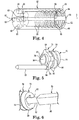
- FIG. 5 is a perspective view the tine assembly 54 of FIG. 3 , according to the present disclosure.
- the tine assembly 54 can include at least one tine 68, a driver member 70, and a carrier member 72.
- the embodiment of FIGS. 3 and 5 includes four tines 68 ( FIG. 7 ), two shown in FIG. 3 , one shown in FIG. 5 with the remaining three omitted for clarity.
- the at least one tine 68 is formed of a material having a shape memory, for example nitinol or a gold/stainless steel alloy, such that the at least one tine 68 can biased to be curved configuration when unrestrained and outside of the housing 52 ( FIG. 7 ) and can be in a linear configuration when restrained by the housing 52, as shown in FIG. 3 and 5 .
- the at least one tine 68 can be pointed for ease in entering tissue for fixation.
- the driver member 70 can include a threaded portion 74, a flange 76, and a hub 78.
- the threaded portion 74 includes external screw threads 80 for threaded engagement with the internal screw threads 64 of the housing 52.
- the hub 78 connects the flange 76 to the threaded portion 74.
- the flange 76 extends radially outward from the hub 78.
- the driver member 70 can also define a driver lumen 82 extending through the threaded portion 74, the hub 78 and the flange 76.
- the driver lumen 82 can be coaxial with the housing lumen 62 as shown in FIG. 3 .
- the driver member 70 can be a one-piece, monolithic structure, whereby, the flange 76 can be formed shaping, or flanging, an end of the hub 78 opposite the threaded portion 74 radially outward to form the flange 76
- the end of the hub 78 may need to be heated until it softens, before flanging the heated end of the hub 78 outward to form the flange 76.
- the driver member 70 can alternatively be a two-piece structure in which the flange 76 and the hub 78 may be a single piece that connects to the threaded portion 74 by, for example, a snap joint or an adhesive joint.
- the hub 78 and the threaded portion 74 may be a single piece that connects to the flange 76 by, for example, an adhesive joint or a weld.
- the driver member 70 can be made of a biocompatible metal, such as stainless steel, Elgiloy, MP35N, or titanium, or a biocompatible polymer that is rigid at body temperature, such as polyetheretherketone (PEEK) or polyethersulfone (PES), or a combination of any of the foregoing materials.
- the driver member 70 can be formed by, for example, molding, machining, or 3D additive manufacturing. Should the at least one tine 68 and the driver member 70 be formed of conductive materials, the flange 76 can be adequately spaced from the at least one tine 68 so that the electrode 48 and the shaft 56 are electrically insulated from the at least one tine 68.
- the threaded portion 74 can be formed of a metal while the flange 76 is formed of a non-conductive polymer to maintain electrical isolation between the shaft 56 and the at least one tine 68.
- the carrier member 72 can include at least one lobe 84 (two shown in FIG. 3 , four in the embodiment of FIG. 3 , as shown in FIG. 5 ) at a circumference of the carrier member 72.
- the at least one tine 68 can be attached to, and project from the at least one lobe 84.
- each of the four tines 68 is attached to one of the four lobes 84.
- the tines 68 can be attached by, for example, molding the lobes 84 around the tines 68, as shown in FIG. 3 .
- the tines 68 can be attached to the lobes 84 by a mechanical fastener, adhesive, or other suitable means.
- the carrier member 72 can define a carrier lumen 86 through which the hub 78 passes.
- An inner diameter of the carrier lumen 86 is sufficiently larger than an outer diameter of the hub 78 such that the carrier member 72 is rotatably disposed around the hub 78.
- the flange 76 and the threaded portion 74 constrain the movement of the carrier member 72 in the axial direction, but not so tightly as to prevent or interfere with the ability of the carrier member 72 to rotate relative to the hub 78.
- the carrier member 72 can be made of a biocompatible polymer that is rigid at body temperature and will thread well through the housing 52 without sticking, such as polyoxymethylene (POM) or polyetheretherketone (PEEK).
- the carrier member 72 can be formed by, for example, molding, machining, or 3D additive manufacturing.
- the rotatable shaft 56 can be a one-piece structure including a main shaft portion 88, a proximal shaft portion 90 on a proximal end of the main shaft portion 88, a distal shaft portion 92 on a distal end of the main shaft portion 88, and an electrode shaft portion 94 extending distally from the distal shaft portion 92.
- the shaft 56 extends through the housing 52At least a portion of main shaft portion 88 and the proximal shaft portion 90 can extend proximally from the proximal end 58 of the housing 52.
- the electrical conductor 44 can be mechanically and electrically connected to the proximal shaft portion 90.
- the electrode shaft portion 94 extends distally from the distal end 60 of the housing 52.
- the distal shaft portion 92 is narrower than a diameter of the narrow portion 67 of the housing lumen 62, and the main shaft portion 88 is wider than the narrow portion 67, to limit the movement of the shaft 56 in the direction of the distal end 60.
- the proximal shaft portion 90 can include a stylet engagement structure 96 so that the stylet 50 can engage the fixation device 38, as shown in FIG. 3 .
- the stylet engagement structure 96 can be a slot, as shown, to engage a flat-bladed stylet, or can be other shapes to engage other types of styles, such as a cross-recess, a hexagonal recess, or a star recess.
- the shaft 56 is preferably conductive and can be made of a biocompatible metal, for example, stainless steel, Elgiloy, MP35N, or titanium.
- the shaft 56 can be made of a combination of the biocompatible metal and a biocompatible polymer that is rigid at body temperature, such as polyetheretherketone (PEEK) or polyethersulfone (PES).
- PEEK polyetheretherketone
- PES polyethersulfone
- the shaft 56 can be made of a biocompatible conductive polymer, for example a biocompatible polymer doped with a biocompatible conductive material such as carbon, titanium, platinum, or gold.
- the shaft 56 can be formed by, for example, molding, machining, or 3D additive manufacturing.
- the electrode 48 can include a cylindrical portion 98 and a conical tip 100 extending distally from the cylindrical portion 98.
- the conical tip 100 can have an axis B that is collinear with the longitudinal axis A of the housing lumen 62.
- the conical tip 100 can be sharpened to enable better penetration into the tissues of the heart 16 and contact the bundle of His 26 ( FIG. 1 ).
- the conical tip 100 can be as short as 1 mm, 2 mm, 3 mm or 4 mm, or as long as 5 mm, 6 mm, 7 mm, or 8 mm, or any length between any two of the preceding lengths.
- the conical tip 100 can have a length from 1 mm to 8 mm, 2 mm to 7 mm, 3 mm to 6 mm, 4 mm to 5 mm, 1 mm to 3 mm, or 2 mm to 3 mm. In some embodiments, the conical tip 100 can be about 2.5 mm long. All lengths are measured from the cylindrical portion 98 to the end of conical tip 100 along the axis B.
- the electrode 48 can further include an O-ring channel 102 to contain an O-ring seal 104.
- the electrode 48 can be disposed at the distal end 60 of the housing 52.
- the electrode 48 is mechanically and electrically connected to the electrode shaft portion 94.
- the electrode 48 can be connected to the electrode shaft portion 94 by, for example, welding, bonding with a conductive eutectic alloy, or bonding with a conductive adhesive.
- the O-ring channel 102 can surround the connection between the electrode 48 and the electrode shaft portion 94 so that the O-ring seal 104 can provide a liquid seal to prevent body fluids from leaking into the housing 52.
- FIG. 6 is an exploded perspective view of an end of the tine assembly 54 and the shaft 56, according to the present disclosure.
- the main shaft portion 88 can have a square cross-sectional shape, while the distal shaft portion 92 can have a circular cross-sectional shape.
- the driver lumen 82 through the threaded portion 74 of the driver member 70 also has a square cross-sectional shape corresponding to the square cross-sectional shape of the main shaft portion 88 so that when the rotatable shaft 56 rotates, the main shaft portion 88 engages the threaded portion 74 of the driver member 70 to rotate the threaded portion 74. While the embodiment shown in FIG.
- the fixation device 38 can be made by attaching the at least one tine 68 to the at least one lobe 84 of the carrier member 72, as described above.
- the hub 78 extending from the threaded portion 74 of the driver member 70 can be inserted through the carrier lumen 86.
- the flange 76 can be formed at an end of the hub 78 opposite the threaded portion 74, as described above, such that the carrier member 72 is rotatable about the hub 78, and the flange 76 and the threaded portion 74 restrain the axial movement of the carrier member 72.
- the at least one tine 68 can be inserted into the at least one slot 66 at the proximal end 58 of the housing 52 in the linear configuration.
- the at least one tine 68 is constrained by the housing 52 to prevent it from self-biasing back to the curved configuration.
- the carrier member 72 is inserted into the housing lumen 62 as the at least one lobe 84 slides within the at least one slot 66.
- the threaded portion 74 of the drive member 70 is threaded into the internal screw threads 64 at the proximal end 58 of the housing 52.
- the shaft 56 is inserted through the driver lumen 82 of the driver member 70 at the proximal end 58 of the housing 52 until the movement of the shaft 56 in the direction of the distal end 60 is limited by the narrow portion 67 of the housing lumen 62 which prevents further movement of the main shaft portion 88.
- the electrode 48 is connected to the electrode shaft portion 94 of the shaft 56 as described above.
- the O-ring seal 104 can be placed in the O-ring channel 102 and around the electrode shaft portion 94 before the electrode 48 is connected to the electrode shaft portion 94.
- the system 10 with the lead 14 having the fixation device 38 as described above can be used in the undeployed state shown in FIG. 3 to map one of the locations described above in reference to FIG. 1 for accessing the bundle of His 26.
- the electrode 48 can penetrate into the myocardium at a first spot near the bundle of His 26, measurements made, the electrode 48 quickly removed from the myocardium and moved to a second spot where the process is repeated.
- the actions of penetrating the myocardium with the electrode 48 by simply pushing on the lead 14 and removing the electrode 48 from the myocardium by simply pulling on the lead 14 are faster and may cause less tissue damage than the prior art which required many turns of a helical electrode to either penetrate the myocardium or remove the electrode.
- the present disclosure permits rapid and accurate mapping before positioning of the lead 14 close enough to the bundle of His 26 for efficient and effective pacing.
- the fixation device 38 can be deployed to fixate the lead 14.
- the fixation device 38 can be deployed by rotating stylet 50 in a first direction (e.g. clockwise) to rotate the shaft 56 as describe above.
- the fixation device 38 can be deployed by rotating the terminal pin 46 in the first direction to rotate the electrical conductor 44 which rotates the shaft 56.
- rotating the shaft 56 in the first direction causes the tine assembly 54 to move through the housing 52 in the direction of the distal end 60.
- the driver member 70 also rotates as the main shaft portion 88 engages the driver lumen 82, as described above.
- the driver lumen 82 is sized to that the driver member 70 can slide along the shaft 56 while the main shaft portion 88 engages the driver lumen 82.
- the external threads 80 on the threaded portion 74 of the driver member 70 engage the internal screw threads 64 of the housing lumen 62, driving the driver member 70 toward the distal end 60.
- the driver member 70 pushes the carrier member 72 through the housing lumen 62, moving the attached at least one tine 68 through the at least one slot 66 to transition the at least one tine 68 from the linear configuration to the curved configuration. Because the carrier member 72 is rotatably disposed around the driver member 70, the carrier member 72 need not rotate with the driver member 70. However, frictional forces between the driver member 70 and the carrier member 72 may impart a slight rotational force on the carrier member 72. The at least one lobe 84 disposed in the at least one slot 66 prevents the carrier member 72 from rotating with the driver member 70 in response to the slight rotational force as the carrier member 72 moves through the housing lumen 62.
- FIG. 7 is a perspective view of the fixation device 38 of FIG. 3 in a deployed state, according to the present disclosure.
- the lead body 34 is omitted for clarity.
- the conical tip 100 of the electrode 48 has penetrated the myocardium M (position indicated with dotted line).
- each of the four tines 68 shown in FIG. 7 moves through one of the four slots 66 and begins to exit the housing 52 at the distal end 60 as they transition from the liner configuration of FIG. 3 to the curved configuration shown in FIG. 7 .
- Each of the tines 68 penetrates the myocardium M and, unconstrained by the housing 52, self-biases to the curved configuration outside of the housing 52 as it penetrates through the myocardium, carving a curved path through the myocardium M.
- each of the four tines 68 is oriented to self-bias to the curved configuration in a direction curving away from the electrode 48.
- Other embodiments may have different orientations for the at least one tine 68. So deployed, the fixation device 38 fixates the lead 14 ( FIG. 1 ) at the desired location.
- the fixation device 38 may be less likely to move from the desired location than prior art devices.
- the electrode 48 penetrates the myocardium M before the fixation device 38 is deployed, helping to stabilize the electrode 48 during deployment, even though the electrode 48 will rotate with the shaft 56 during deployment.
- there should be little recoil from the force required to fixate the lead 14 because the tines 68 can deploy nearly straight out of the slots 66 and penetrate the myocardium M before substantially curving. Further, as the tines 68 deploy, they may tend to pull the electrode 48 into more secure contact with the myocardium M.
- the fixation device 38 may be removed from the myocardium M by rotating the shaft 56 in a second direction opposite the first direction (e.g. counter-clockwise). Rotating the shaft 56 in the second direction causes the tine assembly 54 to move through the housing 52 in the direction of the proximal end 58.
- the driver member 70 rotates as the external threads 80 on the threaded portion 74 of the driver member 70 engage the internal screw threads 64 of the housing lumen 62, to drive the driver member 70 toward the proximal end 58.
- the driver member 70 pulls the carrier member 72 through the housing lumen 62, pulling the attached four tines 68 out of the myocardium M and back into their respective slots 66. Once the four tines 68 are out of the myocardium M, the conical tip 100 of the distal electrode can be pulled from the myocardium M to remove the fixation device 38.
- FIG. 8 is schematic cross-sectional view of the distal end 42 of the lead 14 of FIG. 2 including another device for the active fixation of the lead 14, according to the present disclosure.
- FIG. 8 shows a fixation device 106.
- the fixation device 106 is substantially similar to the fixation device 38 described above in reference FIGS. 3-7 , except that the electrode 48 is replaced by the electrode 108 and the O-ring seal 104 is replaced by a gasket seal 110.
- the electrode 108 is substantially similar to the electrode 48, except that it does not include the O-ring channel 102.
- the gasket seal 110 is a flat gasket defining at least one tine hole 112 (two shown) and a shaft hole 114.
- the at least one tine hole 112 is smaller than a diameter of the at least one tine 68 so that after the at least one tine 68 deploys, the gasket seal 110 will seal around the at least one tine 68 to prevent leakage of bodily fluids into the housing 52.
- the at least one tine hole 112 may be only a slit in the gasket seal 110.
- the at least one tine hole 112 may not be formed until the at least one tine 68 deploys and punches through the gasket seal 110, forming the at least one tine hole 112.
- the shaft hole 114 is smaller than a diameter of the distal shaft portion 92 will seal around the distal shaft portion 92 to prevent leakage of bodily fluids into the housing 52.
- the electrode 48 with the O-ring channel 102 and the O-ring seal 104 can be used in combination with the gasket seal 110 as described above.
- FIG. 9 is schematic cross-sectional view of the distal end 42 of the lead 14 of FIG. 2 including another device for the active fixation of the lead 14, according to the present disclosure.
- FIG. 9 shows a fixation device 116.
- the fixation device 116 is substantially similar to the fixation device 38 described above in reference FIGS. 3-7 , except that it includes at least one tine conductor 118 (two shown, four in total).
- the at least one tine conductor 118 extends from the connector assembly 36 ( FIG. 1 ) to the at least one tine 68 to electrically connect the at least one tine 68 to the connector assembly 36.
- the at least one tine 68 can be electrically conductive and can be electrically insulated from the electrode 48 and the shaft 56.
- the pulse generator 12 can employ the at least one tine 68 as another pacing electrode, controlled separately from the electrode 48. As shown in FIG. 9 , the four tines 68 could provide four additional, individually controllable electrodes for programmable His pacing.
- the at least one tine 68 consists of four tines 68, the at least one slot 66 consisted of four slots 66, the at least one lobe 84 consisted of four lobes 84, and the at least one tine conductor 118 consisted of four tine conductors 118.
- embodiments can include only a single tine 68 or a plurality of tines 68, including 2, 3, 5, 6, 7, 8, 9, or 10 or more tines 68. It is further understood that embodiments can include only a single slot 66 or a plurality of slots 66, so long as the number of slots 66 is at least equal to the number of tines 68. It is further understood that embodiments can include only a single lobe 84 or a plurality of lobes 84. It is further understood that embodiments can include only a single tine conductor 118 or a plurality of tine conductors 118.
Landscapes
- Health & Medical Sciences (AREA)
- Cardiology (AREA)
- Public Health (AREA)
- Veterinary Medicine (AREA)
- Radiology & Medical Imaging (AREA)
- Life Sciences & Earth Sciences (AREA)
- Animal Behavior & Ethology (AREA)
- General Health & Medical Sciences (AREA)
- Biomedical Technology (AREA)
- Nuclear Medicine, Radiotherapy & Molecular Imaging (AREA)
- Engineering & Computer Science (AREA)
- Heart & Thoracic Surgery (AREA)
- Vascular Medicine (AREA)
- Electrotherapy Devices (AREA)
- Neurology (AREA)
- Neurosurgery (AREA)
Abstract
Description
- This application claims priority to United States Provisional Application No.
62/534,584, filed July 19, 2017 N2019577, filed September 19, 2017 - The present disclosure relates to medical devices and methods for the active fixation of an implantable medical lead. More specifically, the disclosure relates to devices and methods for active fixation of implantable medical leads for mapping and stimulating the bundle of His in a patient's heart.
- Cardiac rhythm management systems are useful for electrically stimulating a patient's heart to treat various cardiac arrhythmias. A method of electrically stimulating the heart can include stimulating the His bundle at a location proximate to the tricuspid valve at the interatrial septum in the right atrium of the heart or at a location proximate to the tricuspid valve at the interventricular septum in the right ventricle of the heart. Directly stimulating the bundle of His can simultaneously pace both the right and left ventricles of the heart, potentially avoiding pacing induced dissynchrony which may occur with right ventricular apex pacing. There is a continuing need for improved His bundle lead designs and assemblies.
- The present disclosure relates to a device for the active fixation of an implantable medical lead. The device includes a housing, a tine assembly, and further preferably an electrode, and a rotatable shaft for transitioning of the at least one tine between a linear configuration and a curved configuration. The housing includes a proximal end for connecting to the lead and a distal end opposite the proximal end. The housing defines a housing lumen having a longitudinal axis extending between the proximal end and the distal end. The tine assembly is disposed within the housing lumen. The tine assembly includes at least one tine configured to self-bias from a linear configuration within the housing to a curved configuration outside of the housing. The electrode is disposed at the distal end of the housing. The rotatable shaft is connected to the electrode and extends through the housing lumen. The shaft is configured to engage the tine assembly such that rotation of the shaft transitions the at least one tine between the linear configuration and the curved configuration.
- The housing preferably further includes internal screw threads extending along the housing lumen, and the tine assembly preferably further includes a driver member and a carrier member. The driver member is disposed within the housing lumen. The driver member defines a driver lumen that is coaxial with the housing lumen. The driver member includes a threaded portion having external screw threads engaged with the internal screw threads of the housing, a flange, and a hub connecting the flange to the threaded portion. The carrier member is rotatably disposed around the hub of the driver member. The at least one tine is connected to and projecting from the carrier member. The rotatable shaft extends through the driver lumen. The shaft is configured to engage the driver member such that rotation of the shaft rotates the driver member to transition the at least one tine between the linear configuration and the curved configuration.
- The flange and the threaded portion of the driver member preferably constrain axial movement of the carrier member.
- The housing preferably further defines at least one slot at least partially radially outward from the internal screw threads, the at least one slot extending from the proximal end to the distal end and parallel to the longitudinal axis.
- The carrier member preferably includes at least one lobe configured to engage the at least one slot to prevent axial rotation of the carrier member relative to the housing while permitting the carrier member to move through the housing lumen while the shaft rotates the driver member, the at least one tine connected to and projecting from the at least one lobe.
- The driver lumen is preferably sized so that the driver member can slide along the shaft while the shaft rotates the driver member.
- Rotation of the shaft in a first direction can move the at least one tine out of the housing lumen, transitioning the at least one tine from the linear configuration to the curved configuration to fix the lead to tissue, and rotation of the shaft in a second direction opposite the first direction can retract the at least one tine into the housing lumen, transitioning the at least one tine from the curved configuration to the linear configuration.
- The at least one tine can be conductive and the electrode and the shaft may be electrically insulated from the at least one tine.
- The tine assembly can include a plurality of tines.
- The electrode may include a conical tip having an axis that is collinear with the longitudinal axis of the housing lumen.
- The shaft is preferably electrically and mechanically connected to the electrode.
- The present disclosure also relates to an implantable medical lead including a flexible, tubular lead body including a proximal end and a distal end, a connector assembly disposed at the proximal end, an electrical conductor extending from the connector assembly to the distal end, and the above referred to device, which is disposed at the distal end of the lead body. The electrical conductor can be mechanically and electrically connected to the shaft.
- The present disclosure also relates to a method of making the above referred to device. The method preferably includes attaching at least one tine to a carrier member, inserting a hub extending from a threaded portion of a driver member through the carrier member such that the carrier member is rotatable about the hub, forming a flange at an end of the hub opposite the threaded portion of the driver member, inserting the at least one tine into a proximal end of a longitudinal slot of a housing lumen of a housing to place the at least one tine in a linear configuration contained by the housing, threading the threaded portion of the drive member into a threaded portion at a proximal end of the housing, inserting a shaft through the a driver lumen of the driver member at the proximal end of the housing and through the housing lumen to a distal end of the housing, and connecting an electrode to the shaft at the distal end of the housing. The tine is self-biasing to a curved configuration. The flange and the threaded portion of the driver member preferably restrain the axial movement of the carrier member.
- A seal can be placed around the shaft at the distal end of the housing before connecting the electrode to the shaft.
- Forming the flange at the end of the hub can include heating the end of the hub until it softens and flanging the heated hub outward to form the flange.
- Further aspects of the disclosure are referred to in the claims.
- While multiple embodiments are disclosed, still other embodiments of the present disclosure will become apparent to those skilled in the art from the following detailed description, which shows and describes illustrative embodiments of the disclosure. Accordingly, the drawings and detailed description are to be regarded as illustrative in nature and not restrictive.
-
-
FIG. 1 is a schematic view of the system for mapping and stimulating the bundle of His in a patient's heart, including a lead according to the present disclosure. -
FIG. 2 is a perspective view of the lead ofFIG. 1 , according to the present disclosure. -
FIG. 3 is schematic cross-sectional view of a distal end of the lead ofFIG. 2 showing a device for the active fixation of the lead in an undeployed state, according to the present disclosure. -
FIG. 4 is a transparent perspective view of a housing of the fixation device ofFIG. 3 for the active fixation of the lead, according to the present disclosure. -
FIG. 5 is a perspective view of some of a tine assembly ofFIG. 3 for the active fixation of the lead, according to the present disclosure. -
FIG. 6 is an exploded perspective view of an end of the tine assembly and a rotatable shaft ofFIG. 3 , according to the present disclosure. -
FIG. 7 is a perspective view of the device ofFIG. 3 for the active fixation of the lead in a deployed state. -
FIG. 8 is schematic cross-sectional view of a distal end of the lead ofFIG. 2 including another device for the active fixation of the lead, according to the present disclosure. -
FIG. 9 is schematic cross-sectional view of a distal end of the lead ofFIG. 2 including yet another device for the active fixation of the lead, according to the present disclosure. - While the disclosure is amenable to various modifications and alternative forms, specific embodiments have been shown by way of example in the drawings and are described in detail below. The intention, however, is not to limit the disclosure to the particular embodiments described. On the contrary, the disclosure is intended to cover all modifications, equivalents, and alternatives falling within the scope of the disclosure as defined by the appended claims.
-
FIG. 1 is a schematic view ofsystem 10 for mapping and stimulating the bundle of His, according to the present disclosure. As shown inFIG. 1 , thesystem 10 includes animplantable pulse generator 12 coupled to alead 14 deployed in a patient'sheart 16. Thepulse generator 12 generates an electrical pacing stimulus to be delivered to theheart 16. Thelead 14 operates to convey electrical signals and stimuli between theheart 16 and thepulse generator 12. As further shown inFIG. 1 , theheart 16 includes aright atrium 18 and aright ventricle 20 separated by atricuspid valve 22. In the embodiment shown inFIG. 1 , thelead 14 enters the vascular system through a vascular entry site (not shown) and asuperior vena cava 24 to be implanted in theright atrium 18. The bundle of His 26 can be stimulated at an atrial location proximate to thetricuspid valve 22 at aninteratrial septum 28 in theright atrium 18, as shown inFIG. 1 . This location is proximate to the apex of the triangle of Koch. Alternatively, the bundle of His 24 can be stimulated at a ventricular location proximate to thetricuspid valve 22 at aninterventricular septum 32 in theright ventricle 20 by passing thelead 14 through thetricuspid valve 22 and into theright ventricle 20. - The
system 10 allows direct therapeutic stimulation of the bundle of His 26 by fixating thelead 14 at one of the locations describe above. Mapping at one of the locations described above is necessary to be able to position thelead 14 close enough to the bundle of His 26 for efficient and effective pacing. Some prior art leads rely on non-contact sensing or surface contact sensing with electrodes to map the location of the bundle of His 26. However, in some instances, this may not be accurate enough to identify the proper location to implant thelead 14. Such precise mapping can require repeated penetration of the myocardium to achieve the sensitivity necessary to accurately locate the bundle of His 26. In some other prior art leads, a helical electrode can be employed to repeatedly penetrate the myocardium to locate the bundle of His 26. However, repeatedly implanting and removing the helical electrode, which requires multiple rotations of the helical electrode, can be time consuming and may damage the myocardium. In addition, once a suitable location is found, the recoil from the force required to implant the helical electrode to fixate the prior art lead can result in the helical electrode moving from the identified location and being implanted in a less suitable location. Embodiments of the present disclosure permit mapping that is faster and less harmful to the myocardium, while employing a fixation device that accurately secures a lead electrode in the myocardium. -
FIG. 2 is a perspective view of thelead 14 ofFIG. 1 , according to the present disclosure. As shown inFIG. 2 , thelead 14 includes alead body 34, aconnector assembly 36, and afixation device 38. Thelead body 34 is a flexible tubular body including aproximal end 40 and adistal end 42, and containing an electrical conductor 44 (FIG. 3 ) extending from theproximal end 40 to thedistal end 42. Theconnector assembly 36 is disposed at theproximal end 40 and includes aterminal pin 46 mechanically and electrically connected to theelectrical conductor 44. Theconnector assembly 36 is configured to mechanically and electrically couple the lead 14 to the pulse generator 12 (FIG. 1 ). Thefixation device 38 is a device for the active fixation of thelead 14. Thefixation device 38 is disposed at thedistal end 42 of thelead 14 and includes anelectrode 48. In the embodiment ofFIG. 2 , theelectrical conductor 44 is electrically connected to theelectrode 48 so that it can function as an active electrode to stimulate the bundle of His 26 (FIG. 1 ). - The
electrical conductor 44 can be a coil conductor and thefixation device 38 can be configured such that rotation of theterminal pin 46 rotates theelectrical conductor 44 to cause thefixation device 38 to fixate thelead 14, as described below. Astylet 50 can be extended throughconnector assembly 36 and thelead body 34 to thefixation device 38 and engage thefixation device 38 such that rotation of thestylet 50 causes thefixation device 38 to fixate thelead 14, as described below. -
FIG. 3 is schematic cross-sectional view of thedistal end 42 of thelead 14 ofFIG. 2 including thefixation device 38, according to the present disclosure. InFIG. 3 , thefixation device 38 is shown in an undeployed stated. As shown inFIG. 3 , in addition to theelectrode 48, thefixation device 38 can further include ahousing 52, atine assembly 54, and arotatable shaft 56.FIG. 4 is a transparent perspective view of thehousing 52 of thefixation device 38 ofFIG. 3 , according to embodiments of this disclosure. ConsideringFIGS. 3 and4 together, thehousing 52 can include aproximal end 58 and adistal end 60 opposite theproximal end 58. Thehousing 52 can define ahousing lumen 62,internal screw threads 64, and at least one slot 66 (two shown inFIG. 3 , four shown inFIG. 4 ). Thehousing lumen 62 can include anarrow portion 67 at thedistal end 60 and have a longitudinal axis A extending between theproximal end 58 and thedistal end 60 of thehousing 52. Theinternal screw threads 64 can extend along a portion of thehousing lumen 62 from theproximal end 58 of thehousing 52. The at least oneslot 66 is formed at least partially radially outward from theinternal screw threads 64 and extends longitudinally from theproximal end 58 to thedistal end 60 of thehousing 52 and is parallel to the longitudinal axis A. Thehousing 52 can be made of a biocompatible polymer that is rigid at body temperature, such as polyetheretherketone (PEEK) or polyethersulfone (PES). Thehousing 52 can be formed by, for example, molding, machining, or 3D additive manufacturing. -
FIG. 5 is a perspective view thetine assembly 54 ofFIG. 3 , according to the present disclosure. ConsideringFIGS. 3 and5 together, thetine assembly 54 can include at least onetine 68, adriver member 70, and acarrier member 72. The embodiment ofFIGS. 3 and5 includes four tines 68 (FIG. 7 ), two shown inFIG. 3 , one shown inFIG. 5 with the remaining three omitted for clarity. The at least onetine 68 is formed of a material having a shape memory, for example nitinol or a gold/stainless steel alloy, such that the at least onetine 68 can biased to be curved configuration when unrestrained and outside of the housing 52 (FIG. 7 ) and can be in a linear configuration when restrained by thehousing 52, as shown inFIG. 3 and5 . The at least onetine 68 can be pointed for ease in entering tissue for fixation. - The
driver member 70 can include a threadedportion 74, aflange 76, and ahub 78. The threadedportion 74 includesexternal screw threads 80 for threaded engagement with theinternal screw threads 64 of thehousing 52. Thehub 78 connects theflange 76 to the threadedportion 74. Theflange 76 extends radially outward from thehub 78. Thedriver member 70 can also define adriver lumen 82 extending through the threadedportion 74, thehub 78 and theflange 76. Thedriver lumen 82 can be coaxial with thehousing lumen 62 as shown inFIG. 3 . - As shown in
FIG. 3 , thedriver member 70 can be a one-piece, monolithic structure, whereby, theflange 76 can be formed shaping, or flanging, an end of thehub 78 opposite the threadedportion 74 radially outward to form theflange 76 The end of thehub 78 may need to be heated until it softens, before flanging the heated end of thehub 78 outward to form theflange 76. Thedriver member 70 can alternatively be a two-piece structure in which theflange 76 and thehub 78 may be a single piece that connects to the threadedportion 74 by, for example, a snap joint or an adhesive joint. Alternatively, thehub 78 and the threadedportion 74 may be a single piece that connects to theflange 76 by, for example, an adhesive joint or a weld. - The
driver member 70 can be made of a biocompatible metal, such as stainless steel, Elgiloy, MP35N, or titanium, or a biocompatible polymer that is rigid at body temperature, such as polyetheretherketone (PEEK) or polyethersulfone (PES), or a combination of any of the foregoing materials. Thedriver member 70 can be formed by, for example, molding, machining, or 3D additive manufacturing. Should the at least onetine 68 and thedriver member 70 be formed of conductive materials, theflange 76 can be adequately spaced from the at least onetine 68 so that theelectrode 48 and theshaft 56 are electrically insulated from the at least onetine 68. When thedriver member 70 is a two-piece structure, the threadedportion 74 can be formed of a metal while theflange 76 is formed of a non-conductive polymer to maintain electrical isolation between theshaft 56 and the at least onetine 68. - The
carrier member 72 can include at least one lobe 84 (two shown inFIG. 3 , four in the embodiment ofFIG. 3 , as shown inFIG. 5 ) at a circumference of thecarrier member 72. The at least onetine 68 can be attached to, and project from the at least onelobe 84. In the embodiment ofFIGS 3 and5 , each of the fourtines 68 is attached to one of the fourlobes 84. Thetines 68 can be attached by, for example, molding thelobes 84 around thetines 68, as shown inFIG. 3 . Alternatively, thetines 68 can be attached to thelobes 84 by a mechanical fastener, adhesive, or other suitable means. Thecarrier member 72 can define acarrier lumen 86 through which thehub 78 passes. An inner diameter of thecarrier lumen 86 is sufficiently larger than an outer diameter of thehub 78 such that thecarrier member 72 is rotatably disposed around thehub 78. As shown inFIG. 3 , so configured, theflange 76 and the threadedportion 74 constrain the movement of thecarrier member 72 in the axial direction, but not so tightly as to prevent or interfere with the ability of thecarrier member 72 to rotate relative to thehub 78. - The
carrier member 72 can be made of a biocompatible polymer that is rigid at body temperature and will thread well through thehousing 52 without sticking, such as polyoxymethylene (POM) or polyetheretherketone (PEEK). Thecarrier member 72 can be formed by, for example, molding, machining, or 3D additive manufacturing. - As shown in
FIG. 3 , therotatable shaft 56 can be a one-piece structure including amain shaft portion 88, aproximal shaft portion 90 on a proximal end of themain shaft portion 88, adistal shaft portion 92 on a distal end of themain shaft portion 88, and anelectrode shaft portion 94 extending distally from thedistal shaft portion 92. Theshaft 56 extends through the housing 52At least a portion ofmain shaft portion 88 and theproximal shaft portion 90 can extend proximally from theproximal end 58 of thehousing 52. As shown inFIG. 3 , theelectrical conductor 44 can be mechanically and electrically connected to theproximal shaft portion 90. Theelectrode shaft portion 94 extends distally from thedistal end 60 of thehousing 52. Thedistal shaft portion 92 is narrower than a diameter of thenarrow portion 67 of thehousing lumen 62, and themain shaft portion 88 is wider than thenarrow portion 67, to limit the movement of theshaft 56 in the direction of thedistal end 60. Theproximal shaft portion 90 can include astylet engagement structure 96 so that thestylet 50 can engage thefixation device 38, as shown inFIG. 3 . Thestylet engagement structure 96 can be a slot, as shown, to engage a flat-bladed stylet, or can be other shapes to engage other types of styles, such as a cross-recess, a hexagonal recess, or a star recess. - The
shaft 56 is preferably conductive and can be made of a biocompatible metal, for example, stainless steel, Elgiloy, MP35N, or titanium. Theshaft 56 can be made of a combination of the biocompatible metal and a biocompatible polymer that is rigid at body temperature, such as polyetheretherketone (PEEK) or polyethersulfone (PES). Theshaft 56 can be made of a biocompatible conductive polymer, for example a biocompatible polymer doped with a biocompatible conductive material such as carbon, titanium, platinum, or gold. Theshaft 56 can be formed by, for example, molding, machining, or 3D additive manufacturing. - The
electrode 48 can include acylindrical portion 98 and aconical tip 100 extending distally from thecylindrical portion 98. Theconical tip 100 can have an axis B that is collinear with the longitudinal axis A of thehousing lumen 62. Theconical tip 100 can be sharpened to enable better penetration into the tissues of theheart 16 and contact the bundle of His 26 (FIG. 1 ). Theconical tip 100 can be as short as 1 mm, 2 mm, 3 mm or 4 mm, or as long as 5 mm, 6 mm, 7 mm, or 8 mm, or any length between any two of the preceding lengths. Theconical tip 100 can have a length from 1 mm to 8 mm, 2 mm to 7 mm, 3 mm to 6 mm, 4 mm to 5 mm, 1 mm to 3 mm, or 2 mm to 3 mm. In some embodiments, theconical tip 100 can be about 2.5 mm long. All lengths are measured from thecylindrical portion 98 to the end ofconical tip 100 along the axis B. - The
electrode 48 can further include an O-ring channel 102 to contain an O-ring seal 104. Theelectrode 48 can be disposed at thedistal end 60 of thehousing 52. Theelectrode 48 is mechanically and electrically connected to theelectrode shaft portion 94. Theelectrode 48 can be connected to theelectrode shaft portion 94 by, for example, welding, bonding with a conductive eutectic alloy, or bonding with a conductive adhesive. The O-ring channel 102 can surround the connection between theelectrode 48 and theelectrode shaft portion 94 so that the O-ring seal 104 can provide a liquid seal to prevent body fluids from leaking into thehousing 52. -
FIG. 6 is an exploded perspective view of an end of thetine assembly 54 and theshaft 56, according to the present disclosure. As shown inFIG. 6 , themain shaft portion 88 can have a square cross-sectional shape, while thedistal shaft portion 92 can have a circular cross-sectional shape. Thedriver lumen 82 through the threadedportion 74 of thedriver member 70 also has a square cross-sectional shape corresponding to the square cross-sectional shape of themain shaft portion 88 so that when therotatable shaft 56 rotates, themain shaft portion 88 engages the threadedportion 74 of thedriver member 70 to rotate the threadedportion 74. While the embodiment shown inFIG. 6 employs square cross-sectional shapes for themain shaft portion 88 and thedriver lumen 82 through the threadedportion 74, in other embodiments, other non-circular shapes may be employed, including elliptical, rectangular, pentagonal, hexagonal, cross-recess, or star shapes. - Considering
FIGS. 3-6 , thefixation device 38 can be made by attaching the at least onetine 68 to the at least onelobe 84 of thecarrier member 72, as described above. Thehub 78 extending from the threadedportion 74 of thedriver member 70 can be inserted through thecarrier lumen 86. Theflange 76 can be formed at an end of thehub 78 opposite the threadedportion 74, as described above, such that thecarrier member 72 is rotatable about thehub 78, and theflange 76 and the threadedportion 74 restrain the axial movement of thecarrier member 72. The at least onetine 68 can be inserted into the at least oneslot 66 at theproximal end 58 of thehousing 52 in the linear configuration. The at least onetine 68 is constrained by thehousing 52 to prevent it from self-biasing back to the curved configuration. Thecarrier member 72 is inserted into thehousing lumen 62 as the at least onelobe 84 slides within the at least oneslot 66. The threadedportion 74 of thedrive member 70 is threaded into theinternal screw threads 64 at theproximal end 58 of thehousing 52. Theshaft 56 is inserted through thedriver lumen 82 of thedriver member 70 at theproximal end 58 of thehousing 52 until the movement of theshaft 56 in the direction of thedistal end 60 is limited by thenarrow portion 67 of thehousing lumen 62 which prevents further movement of themain shaft portion 88. Theelectrode 48 is connected to theelectrode shaft portion 94 of theshaft 56 as described above. The O-ring seal 104 can be placed in the O-ring channel 102 and around theelectrode shaft portion 94 before theelectrode 48 is connected to theelectrode shaft portion 94. - In operation, the
system 10 with thelead 14 having thefixation device 38 as described above, can be used in the undeployed state shown inFIG. 3 to map one of the locations described above in reference toFIG. 1 for accessing the bundle of His 26. Theelectrode 48 can penetrate into the myocardium at a first spot near the bundle of His 26, measurements made, theelectrode 48 quickly removed from the myocardium and moved to a second spot where the process is repeated. The actions of penetrating the myocardium with theelectrode 48 by simply pushing on thelead 14 and removing theelectrode 48 from the myocardium by simply pulling on thelead 14 are faster and may cause less tissue damage than the prior art which required many turns of a helical electrode to either penetrate the myocardium or remove the electrode. Thus, the present disclosure permits rapid and accurate mapping before positioning of thelead 14 close enough to the bundle of His 26 for efficient and effective pacing. - Once a suitable pacing location is found and the
conical tip 100 of theelectrode 48 has penetrated the myocardium, thefixation device 38 can be deployed to fixate thelead 14. Thefixation device 38 can be deployed by rotatingstylet 50 in a first direction (e.g. clockwise) to rotate theshaft 56 as describe above. When theelectrical conductor 44 is a coil conductor, thefixation device 38 can be deployed by rotating theterminal pin 46 in the first direction to rotate theelectrical conductor 44 which rotates theshaft 56. - In any case, rotating the
shaft 56 in the first direction causes thetine assembly 54 to move through thehousing 52 in the direction of thedistal end 60. As theshaft 56 rotates, thedriver member 70 also rotates as themain shaft portion 88 engages thedriver lumen 82, as described above. Thedriver lumen 82 is sized to that thedriver member 70 can slide along theshaft 56 while themain shaft portion 88 engages thedriver lumen 82. Theexternal threads 80 on the threadedportion 74 of thedriver member 70 engage theinternal screw threads 64 of thehousing lumen 62, driving thedriver member 70 toward thedistal end 60. Thedriver member 70 pushes thecarrier member 72 through thehousing lumen 62, moving the attached at least onetine 68 through the at least oneslot 66 to transition the at least onetine 68 from the linear configuration to the curved configuration. Because thecarrier member 72 is rotatably disposed around thedriver member 70, thecarrier member 72 need not rotate with thedriver member 70. However, frictional forces between thedriver member 70 and thecarrier member 72 may impart a slight rotational force on thecarrier member 72. The at least onelobe 84 disposed in the at least oneslot 66 prevents thecarrier member 72 from rotating with thedriver member 70 in response to the slight rotational force as thecarrier member 72 moves through thehousing lumen 62. -
FIG. 7 is a perspective view of thefixation device 38 ofFIG. 3 in a deployed state, according to the present disclosure. Thelead body 34 is omitted for clarity. Theconical tip 100 of theelectrode 48 has penetrated the myocardium M (position indicated with dotted line). As each of the fourtines 68 shown inFIG. 7 moves through one of the fourslots 66 and begins to exit thehousing 52 at thedistal end 60 as they transition from the liner configuration ofFIG. 3 to the curved configuration shown inFIG. 7 . Each of thetines 68 penetrates the myocardium M and, unconstrained by thehousing 52, self-biases to the curved configuration outside of thehousing 52 as it penetrates through the myocardium, carving a curved path through the myocardium M. In the embodiment shown inFIG. 7 , each of the fourtines 68 is oriented to self-bias to the curved configuration in a direction curving away from theelectrode 48. Other embodiments may have different orientations for the at least onetine 68. So deployed, thefixation device 38 fixates the lead 14 (FIG. 1 ) at the desired location. - The
fixation device 38 may be less likely to move from the desired location than prior art devices. Theelectrode 48 penetrates the myocardium M before thefixation device 38 is deployed, helping to stabilize theelectrode 48 during deployment, even though theelectrode 48 will rotate with theshaft 56 during deployment. In addition, there should be little recoil from the force required to fixate thelead 14 because thetines 68 can deploy nearly straight out of theslots 66 and penetrate the myocardium M before substantially curving. Further, as thetines 68 deploy, they may tend to pull theelectrode 48 into more secure contact with the myocardium M. - If desired, the
fixation device 38 may be removed from the myocardium M by rotating theshaft 56 in a second direction opposite the first direction (e.g. counter-clockwise). Rotating theshaft 56 in the second direction causes thetine assembly 54 to move through thehousing 52 in the direction of theproximal end 58. As theshaft 56 rotates, thedriver member 70 rotates as theexternal threads 80 on the threadedportion 74 of thedriver member 70 engage theinternal screw threads 64 of thehousing lumen 62, to drive thedriver member 70 toward theproximal end 58. Thedriver member 70 pulls thecarrier member 72 through thehousing lumen 62, pulling the attached fourtines 68 out of the myocardium M and back into theirrespective slots 66. Once the fourtines 68 are out of the myocardium M, theconical tip 100 of the distal electrode can be pulled from the myocardium M to remove thefixation device 38. -
FIG. 8 is schematic cross-sectional view of thedistal end 42 of thelead 14 ofFIG. 2 including another device for the active fixation of thelead 14, according to the present disclosure.FIG. 8 shows afixation device 106. Thefixation device 106 is substantially similar to thefixation device 38 described above in referenceFIGS. 3-7 , except that theelectrode 48 is replaced by theelectrode 108 and the O-ring seal 104 is replaced by agasket seal 110. Theelectrode 108 is substantially similar to theelectrode 48, except that it does not include the O-ring channel 102. Thegasket seal 110 is a flat gasket defining at least one tine hole 112 (two shown) and ashaft hole 114. The at least onetine hole 112 is smaller than a diameter of the at least onetine 68 so that after the at least onetine 68 deploys, thegasket seal 110 will seal around the at least onetine 68 to prevent leakage of bodily fluids into thehousing 52. The at least onetine hole 112 may be only a slit in thegasket seal 110. The at least onetine hole 112 may not be formed until the at least onetine 68 deploys and punches through thegasket seal 110, forming the at least onetine hole 112. Similarly, theshaft hole 114 is smaller than a diameter of thedistal shaft portion 92 will seal around thedistal shaft portion 92 to prevent leakage of bodily fluids into thehousing 52. - The
electrode 48 with the O-ring channel 102 and the O-ring seal 104 can be used in combination with thegasket seal 110 as described above. -
FIG. 9 is schematic cross-sectional view of thedistal end 42 of thelead 14 ofFIG. 2 including another device for the active fixation of thelead 14, according to the present disclosure.FIG. 9 shows afixation device 116. Thefixation device 116 is substantially similar to thefixation device 38 described above in referenceFIGS. 3-7 , except that it includes at least one tine conductor 118 (two shown, four in total). The at least onetine conductor 118 extends from the connector assembly 36 (FIG. 1 ) to the at least onetine 68 to electrically connect the at least onetine 68 to theconnector assembly 36. The at least onetine 68 can be electrically conductive and can be electrically insulated from theelectrode 48 and theshaft 56. Thus, when theconnector assembly 36 connects thelead 14 to the pulse generator 12 (FIG. 1 ), thepulse generator 12 can employ the at least onetine 68 as another pacing electrode, controlled separately from theelectrode 48. As shown inFIG. 9 , the fourtines 68 could provide four additional, individually controllable electrodes for programmable His pacing. - As shown in the
FIGS 1-9 , the at least onetine 68 consists of fourtines 68, the at least oneslot 66 consisted of fourslots 66, the at least onelobe 84 consisted of fourlobes 84, and the at least onetine conductor 118 consisted of fourtine conductors 118. However, it is understood that embodiments can include only asingle tine 68 or a plurality oftines 68, including 2, 3, 5, 6, 7, 8, 9, or 10 or more tines 68. It is further understood that embodiments can include only asingle slot 66 or a plurality ofslots 66, so long as the number ofslots 66 is at least equal to the number oftines 68. It is further understood that embodiments can include only asingle lobe 84 or a plurality oflobes 84. It is further understood that embodiments can include only asingle tine conductor 118 or a plurality oftine conductors 118.
Claims (15)
- A device for the active fixation of an implantable medical lead, the device comprising:a housing including a proximal end for connecting to the lead and a distal end opposite the proximal end, the housing defining a housing lumen having a longitudinal axis extending between the proximal end and the distal end;a tine assembly disposed within the housing lumen, the tine assembly including at least one tine configured to self-bias from a linear configuration within the housing to a curved configuration outside of the housing; anda rotatable shaft extending through the housing lumen, the shaft configured to engage the tine assembly such that rotation of the shaft transitions the at least one tine between the linear configuration and the curved configuration.
- The device of claim 1, further including an electrode disposed at the distal end of the housing, the rotatable shaft connected to the electrode.
- The device of claim 1, wherein the housing further includes internal screw threads extending along the housing lumen, and the tine assembly further includes:a driver member disposed within the housing lumen, the driver member defining a driver lumen coaxial with the housing lumen, the driver member including:a threaded portion having external screw threads engaged with the internal screw threads of the housing;a flange; anda hub connecting the flange to the threaded portion; anda carrier member rotatably disposed around the hub of the driver member, the at least one tine connected to and projecting from the carrier member, wherein the rotatable shaft extends through the driver lumen, the shaft configured to engage the driver member such that rotation of the shaft rotates the driver member to transition the at least one tine between the linear configuration and the curved configuration.
- The device of claim 3, wherein the flange and the threaded portion of the driver member constrain axial movement of the carrier member.
- The device of either of claims 3 or 4, wherein the housing further defines at least one slot at least partially radially outward from the internal screw threads, the at least one slot extending from the proximal end to the distal end and parallel to the longitudinal axis; and the carrier member includes at least one lobe configured to engage the at least one slot to prevent axial rotation of the carrier member relative to the housing while permitting the carrier member to move through the housing lumen while the shaft rotates the driver member, the at least one tine connected to and projecting from the at least one lobe.
- The device of any of claims 3-5, wherein the driver lumen is sized so that the driver member can slide along the shaft while the shaft rotates the driver member.
- The device of any of claims 1-6, wherein rotation of the shaft in a first direction moves the at least one tine out of the housing lumen, transitioning the at least one tine from the linear configuration to the curved configuration to fix the lead to tissue, and rotation of the shaft in a second direction opposite the first direction retracts the at least one tine into the housing lumen, transitioning the at least one tine from the curved configuration to the linear configuration.
- The device of any of claims 2-7, wherein the at least one tine is conductive and the electrode and the shaft are electrically insulated from the at least one tine.
- The device of any of claims 1-8, wherein the at least one tine includes a plurality of tines.
- The device of any of claims 2-9, wherein the electrode includes a conical tip having an axis that is collinear with the longitudinal axis of the housing lumen.
- The device of any of claims 2-10, wherein the shaft is electrically and mechanically connected to the electrode.
- An implantable medical lead comprising:a flexible, tubular lead body including a proximal end and a distal end;a connector assembly disposed at the proximal end;an electrical conductor extending from the connector assembly to the distal end; anda device for the active fixation of the implantable medical lead according to any of claims 1-11, the device disposed at the distal end of the lead body, wherein the electrical conductor is mechanically and electrically connected to the shaft.
- A method of making a device for the active fixation of an implantable medical lead, the method comprising:attaching at least one tine to a carrier member, the tine self-biasing to a curved configuration;inserting a hub extending from a threaded portion of a driver member through the carrier member such that the carrier member is rotatable about the hub;forming a flange at an end of the hub opposite the threaded portion of the driver member, the flange and the threaded portion of the driver member restraining the axial movement of the carrier member;inserting the at least one tine into a proximal end of a longitudinal slot of a housing lumen of a housing to place the at least one tine in a linear configuration contained by the housing;threading the threaded portion of the drive member into a threaded portion at a proximal end of the housing;inserting a shaft through a driver lumen of the driver member at the proximal end of the housing and through the housing lumen to a distal end of the housing; and connecting an electrode to the shaft at the distal end of the housing.
- The method of claim 13, further including placing a seal around the shaft at the distal end of the housing before connecting the electrode to the shaft.
- The method of either of claims 13 or 14, wherein forming the flange at the end of the hub includes:heating the end of the hub until it softens; andflanging the heated hub outward to form the flange.
Applications Claiming Priority (2)
| Application Number | Priority Date | Filing Date | Title |
|---|---|---|---|
| US201762534584P | 2017-07-19 | 2017-07-19 | |
| NL2019577A NL2019577B1 (en) | 2017-09-19 | 2017-09-19 | Stimulation/sensing electrode fixation device and electrical lead |
Publications (2)
| Publication Number | Publication Date |
|---|---|
| EP3431134A1 true EP3431134A1 (en) | 2019-01-23 |
| EP3431134B1 EP3431134B1 (en) | 2020-02-12 |
Family
ID=60081236
Family Applications (1)
| Application Number | Title | Priority Date | Filing Date |
|---|---|---|---|
| EP18181790.9A Active EP3431134B1 (en) | 2017-07-19 | 2018-07-04 | Stimulation/sensing electrode fixation device and electrical lead |
Country Status (5)
| Country | Link |
|---|---|
| US (2) | US11464967B2 (en) |
| EP (1) | EP3431134B1 (en) |
| CN (1) | CN109276810B (en) |
| AU (1) | AU2018204610B2 (en) |
| NL (1) | NL2019577B1 (en) |
Families Citing this family (9)
| Publication number | Priority date | Publication date | Assignee | Title |
|---|---|---|---|---|
| NL2019577B1 (en) * | 2017-09-19 | 2019-03-28 | Cardiac Pacemakers Inc | Stimulation/sensing electrode fixation device and electrical lead |
| CN112020374B (en) | 2018-04-23 | 2024-05-07 | 心脏起搏器股份公司 | Multipolar Leads for His Bundle Pacing |
| WO2020081444A1 (en) * | 2018-10-16 | 2020-04-23 | Cardiac Pacemakers, Inc. | His bundle lead with extensible electrode and repositioning features |
| US11253699B1 (en) | 2019-03-21 | 2022-02-22 | Terrell M. Williams | Cardiac pacing lead |
| CN109793989B (en) * | 2019-04-02 | 2021-08-13 | 创领心律管理医疗器械(上海)有限公司 | Leadless pacemakers and leadless pacemaker systems |
| ES2804080B2 (en) * | 2019-08-02 | 2021-08-05 | Miralles Raimundo Vicente | Clamping system for electrical stimulation generator |
| US11826562B2 (en) | 2020-06-09 | 2023-11-28 | Medtronic, Inc. | Implantable medical lead |
| CN216456543U (en) * | 2021-10-08 | 2022-05-10 | 中国医学科学院阜外医院 | A leadless left bundle branch pacemaker |
| US12274876B1 (en) * | 2023-11-02 | 2025-04-15 | The Future Of Pacing L.L.C. | Multielectrode medical lead with fixation |
Citations (4)
| Publication number | Priority date | Publication date | Assignee | Title |
|---|---|---|---|---|
| US20100305670A1 (en) * | 2009-05-26 | 2010-12-02 | Hall Peter C | Method and Devices for Coupling a Lead Conductor Member to a Functional Component |
| US20110251662A1 (en) * | 2010-04-13 | 2011-10-13 | Medtronic Vascular, Inc. | Slidable Fixation Device for Securing a Medical Implant |
| US20150313669A1 (en) * | 2014-05-04 | 2015-11-05 | Diros Technology Inc. | Radiofrequency Probes with Retractable Multi-Tined Electrodes |
| US20170106185A1 (en) * | 2015-10-15 | 2017-04-20 | Pacesetter, Inc. | Fixation sleeve equipped leadless pulse generator |
Family Cites Families (53)
| Publication number | Priority date | Publication date | Assignee | Title |
|---|---|---|---|---|
| US4214804A (en) | 1978-09-25 | 1980-07-29 | Daig Corporation | Press fit electrical connection apparatus |
| US5095916A (en) | 1985-06-20 | 1992-03-17 | Medtronic, Inc. | Cardioversion and defibrillation lead system |
| DE3708133A1 (en) | 1987-03-13 | 1988-09-22 | Bisping Hans Juergen | IMPLANTABLE ELECTRODE PROBE WITH EXTENDABLE SCREW ELECTRODE |
| US5353800A (en) | 1992-12-11 | 1994-10-11 | Medtronic, Inc. | Implantable pressure sensor lead |
| US5476500A (en) * | 1993-12-20 | 1995-12-19 | Ventritex, Inc. | Endocardial lead system with defibrillation electrode fixation |
| US5492119A (en) * | 1993-12-22 | 1996-02-20 | Heart Rhythm Technologies, Inc. | Catheter tip stabilizing apparatus |
| US5683447A (en) * | 1995-12-19 | 1997-11-04 | Ventritex, Inc. | Lead with septal defibrillation and pacing electrodes |
| US6595958B1 (en) | 2000-08-08 | 2003-07-22 | Scimed Life Systems, Inc. | Tortuous path injection device and method |
| US6999819B2 (en) | 2001-08-31 | 2006-02-14 | Medtronic, Inc. | Implantable medical electrical stimulation lead fixation method and apparatus |
| US7546166B2 (en) | 2001-11-29 | 2009-06-09 | Medtronic, Inc. | Medical lead designs for lead placement through tissue |
| US6704605B2 (en) * | 2002-01-31 | 2004-03-09 | Cardiac Pacemakers, Inc. | Medical electrode assembly |
| US7177704B2 (en) | 2002-04-29 | 2007-02-13 | Medtronic, Inc. | Pacing method and apparatus |
| US7151965B2 (en) | 2002-07-19 | 2006-12-19 | Oscor Inc. | Device and method for delivering cardiac leads |
| US7103418B2 (en) | 2002-10-02 | 2006-09-05 | Medtronic, Inc. | Active fluid delivery catheter |
| US7158838B2 (en) * | 2003-01-31 | 2007-01-02 | Medtronic, Inc. | Arrangement for implanting a miniaturized cardiac lead having a fixation helix |
| US7499757B2 (en) | 2003-10-24 | 2009-03-03 | Cardiac Pacemakers, Inc. | Absorbable myocardial lead fixation system |
| US7212871B1 (en) | 2003-12-24 | 2007-05-01 | Pacesetter, Inc. | Epicardial and myocardial leads for implanting in the heart by thoracotomy or port access surgeries with detachable electrode tip |
| US7369901B1 (en) | 2004-02-11 | 2008-05-06 | Pacesetter, Inc. | Myocardial lead and lead system |
| US7747333B2 (en) | 2004-08-16 | 2010-06-29 | Cardiac Pacemakers, Inc. | Lead assembly and methods including a push tube |
| US7212870B1 (en) | 2004-09-16 | 2007-05-01 | Pacesetter, Inc. | Dual helix active fixation stimulation lead |
| CA2583404A1 (en) | 2004-10-20 | 2006-04-27 | Boston Scientific Limited | Leadless cardiac stimulation systems |
| US20060106315A1 (en) | 2004-11-17 | 2006-05-18 | Roger Edens | Guided hypodermic cannula |
| US7433739B1 (en) | 2004-11-30 | 2008-10-07 | Pacesetter, Inc. | Passive fixation mechanism for epicardial sensing and stimulation lead placed through pericardial access |
| US8423139B2 (en) | 2004-12-20 | 2013-04-16 | Cardiac Pacemakers, Inc. | Methods, devices and systems for cardiac rhythm management using an electrode arrangement |
| US7496410B2 (en) | 2005-01-10 | 2009-02-24 | Cardiac Pacemakers, Inc. | Spring fixation mechanism for epicardial leads |
| US8463404B2 (en) | 2005-03-24 | 2013-06-11 | Metacure Limited | Electrode assemblies, tools, and methods for gastric wall implantation |
| US8239039B2 (en) * | 2005-08-30 | 2012-08-07 | Cardiac Pacemakers, Inc. | Device on lead to prevent perforation and/or fixate lead |
| EP1774986B1 (en) | 2005-10-12 | 2008-10-22 | BIOTRONIK CRM Patent AG | Active fixation cardiac lead |
| WO2007053065A1 (en) | 2005-10-31 | 2007-05-10 | St. Jude Medical Ab | Implantable lead with a stimulating electrode and a mapping electrode that is electrically disconnectable |
| US7630761B2 (en) | 2005-11-04 | 2009-12-08 | Cardiac Pacemakers, Inc. | Method and apparatus for modifying tissue to improve electrical stimulation efficacy |
| US8090451B2 (en) | 2006-03-30 | 2012-01-03 | Medtronic Inc. | Transvenous active fixation lead system |
| US8036757B2 (en) | 2006-09-10 | 2011-10-11 | Seth Worley | Pacing lead and method for pacing in the pericardial space |
| US7657326B2 (en) | 2006-11-08 | 2010-02-02 | Cardiac Pacemakers, Inc. | Cardiac lead with a retractable helix |
| US7711437B1 (en) | 2006-11-22 | 2010-05-04 | Pacesetter, Inc. | Lead fixation device |
| US7920928B1 (en) | 2007-01-31 | 2011-04-05 | Pacesetter, Inc. | Passive fixation for epicardial lead |
| US9427573B2 (en) * | 2007-07-10 | 2016-08-30 | Astora Women's Health, Llc | Deployable electrode lead anchor |
| EP2274046B1 (en) | 2008-04-15 | 2012-08-15 | Cardiac Pacemakers, Inc. | Bundle of his stimulation system |
| ATE537542T1 (en) | 2008-10-28 | 2011-12-15 | Koninkl Philips Electronics Nv | REUSE A SCREW HEAD |
| US8346374B2 (en) | 2009-07-09 | 2013-01-01 | Cardiac Pacemakers, Inc. | Laminate distal lead seal with tissue ingrowth feature |
| US8271097B2 (en) | 2009-12-31 | 2012-09-18 | Cardiac Pacemakers, Inc. | MRI safe, multipolar active fixation stimulation lead with co-radial construction |
| US20120004714A1 (en) * | 2010-06-30 | 2012-01-05 | Ryan Kleve | Lead having coil electrode with preferential bending region |
| US9855421B2 (en) * | 2010-09-28 | 2018-01-02 | The Board Of Trustees Of The Leland Stanford Junior University | Device and method for positioning an electrode in tissue |
| US8478429B2 (en) * | 2010-12-28 | 2013-07-02 | Cardiac Pacemakers, Inc. | Extendable/retractable fixation lead with distal travelling seal and related devices |
| WO2013162775A2 (en) | 2012-04-27 | 2013-10-31 | Medtronic, Inc. | Structures and techniques for medical lead fabrication |
| US9883908B2 (en) | 2012-05-02 | 2018-02-06 | The Charlotte-Mecklenburg Hospital Authority | Devices, systems, and methods for treating cardiac arrhythmias |
| JP6357476B2 (en) | 2012-08-30 | 2018-07-11 | カーディアック ペースメイカーズ, インコーポレイテッド | A system that delivers the lead to the bundle of His below the tricuspid valve in the right ventricle |
| EP2719424B1 (en) | 2012-10-12 | 2015-04-08 | Sorin CRM SAS | Intraseptal probe for left ventricular stimulation |
| US9302098B2 (en) | 2013-02-26 | 2016-04-05 | Cardiac Pacemakers, Inc. | Implantable medical device including assembly incorporating radiopaque agent and elutable drug into a polymeric lead tip |
| EP3057523A4 (en) | 2013-10-16 | 2016-10-19 | Medwerks Llc | Atraumatic medical device |
| US20170043158A1 (en) * | 2015-08-12 | 2017-02-16 | Medtronic, Inc. | Interventional medical systems and catheters |
| NL2019577B1 (en) | 2017-09-19 | 2019-03-28 | Cardiac Pacemakers Inc | Stimulation/sensing electrode fixation device and electrical lead |
| CN112020374B (en) | 2018-04-23 | 2024-05-07 | 心脏起搏器股份公司 | Multipolar Leads for His Bundle Pacing |
| WO2020081444A1 (en) * | 2018-10-16 | 2020-04-23 | Cardiac Pacemakers, Inc. | His bundle lead with extensible electrode and repositioning features |
-
2017
- 2017-09-19 NL NL2019577A patent/NL2019577B1/en not_active IP Right Cessation
-
2018
- 2018-06-25 AU AU2018204610A patent/AU2018204610B2/en not_active Ceased
- 2018-07-04 EP EP18181790.9A patent/EP3431134B1/en active Active
- 2018-07-17 CN CN201810782459.XA patent/CN109276810B/en active Active
- 2018-07-18 US US16/038,938 patent/US11464967B2/en active Active
-
2022
- 2022-06-29 US US17/853,271 patent/US11992676B2/en active Active
Patent Citations (4)
| Publication number | Priority date | Publication date | Assignee | Title |
|---|---|---|---|---|
| US20100305670A1 (en) * | 2009-05-26 | 2010-12-02 | Hall Peter C | Method and Devices for Coupling a Lead Conductor Member to a Functional Component |
| US20110251662A1 (en) * | 2010-04-13 | 2011-10-13 | Medtronic Vascular, Inc. | Slidable Fixation Device for Securing a Medical Implant |
| US20150313669A1 (en) * | 2014-05-04 | 2015-11-05 | Diros Technology Inc. | Radiofrequency Probes with Retractable Multi-Tined Electrodes |
| US20170106185A1 (en) * | 2015-10-15 | 2017-04-20 | Pacesetter, Inc. | Fixation sleeve equipped leadless pulse generator |
Also Published As
| Publication number | Publication date |
|---|---|
| CN109276810B (en) | 2022-06-28 |
| US11992676B2 (en) | 2024-05-28 |
| AU2018204610B2 (en) | 2020-07-02 |
| NL2019577B1 (en) | 2019-03-28 |
| US11464967B2 (en) | 2022-10-11 |
| US20220323749A1 (en) | 2022-10-13 |
| EP3431134B1 (en) | 2020-02-12 |
| CN109276810A (en) | 2019-01-29 |
| US20190022379A1 (en) | 2019-01-24 |
| AU2018204610A1 (en) | 2019-02-07 |
Similar Documents
| Publication | Publication Date | Title |
|---|---|---|
| US11992676B2 (en) | Stimulation/sensing electrode fixation device and electrical lead | |
| US11666753B2 (en) | Multipolar lead for His bundle pacing | |
| US12083337B2 (en) | Implantable lead with extensible electrode and repositioning features | |
| US12496452B2 (en) | Multi-electrode implantable medical device (IMD) | |
| JP7036920B2 (en) | Biostimulator with fixed elements | |
| JP2020146464A (en) | Biostimulator with coaxial fixing element | |
| US9192317B2 (en) | Implantable active fixation lead with biodegradable helical tip | |
| US20230012417A1 (en) | Leadless pacing device with coronary sinus leadlet | |
| US11219775B2 (en) | Retention mechanism for an implantable lead | |
| JP5688469B2 (en) | Implantable medical electrical lead | |
| EP4366821A1 (en) | Leadless pacing device with coronary sinus leadlet | |
| US11826562B2 (en) | Implantable medical lead | |
| US20260054057A1 (en) | Cardiac electrode assembly with anti-migration feature |
Legal Events
| Date | Code | Title | Description |
|---|---|---|---|
| STAA | Information on the status of an ep patent application or granted ep patent |
Free format text: STATUS: EXAMINATION IS IN PROGRESS |
|
| PUAI | Public reference made under article 153(3) epc to a published international application that has entered the european phase |
Free format text: ORIGINAL CODE: 0009012 |
|
| 17P | Request for examination filed |
Effective date: 20180704 |
|
| AK | Designated contracting states |
Kind code of ref document: A1 Designated state(s): AL AT BE BG CH CY CZ DE DK EE ES FI FR GB GR HR HU IE IS IT LI LT LU LV MC MK MT NL NO PL PT RO RS SE SI SK SM TR |
|
| AX | Request for extension of the european patent |
Extension state: BA ME |
|
| GRAP | Despatch of communication of intention to grant a patent |
Free format text: ORIGINAL CODE: EPIDOSNIGR1 |
|
| STAA | Information on the status of an ep patent application or granted ep patent |
Free format text: STATUS: GRANT OF PATENT IS INTENDED |
|
| INTG | Intention to grant announced |
Effective date: 20190918 |
|
| GRAS | Grant fee paid |
Free format text: ORIGINAL CODE: EPIDOSNIGR3 |
|
| GRAA | (expected) grant |
Free format text: ORIGINAL CODE: 0009210 |
|
| STAA | Information on the status of an ep patent application or granted ep patent |
Free format text: STATUS: THE PATENT HAS BEEN GRANTED |
|
| AK | Designated contracting states |
Kind code of ref document: B1 Designated state(s): AL AT BE BG CH CY CZ DE DK EE ES FI FR GB GR HR HU IE IS IT LI LT LU LV MC MK MT NL NO PL PT RO RS SE SI SK SM TR |
|
| REG | Reference to a national code |
Ref country code: GB Ref legal event code: FG4D |
|
| REG | Reference to a national code |
Ref country code: CH Ref legal event code: EP |
|
| REG | Reference to a national code |
Ref country code: AT Ref legal event code: REF Ref document number: 1231289 Country of ref document: AT Kind code of ref document: T Effective date: 20200215 |
|
| REG | Reference to a national code |
Ref country code: IE Ref legal event code: FG4D |
|
| REG | Reference to a national code |
Ref country code: DE Ref legal event code: R096 Ref document number: 602018002379 Country of ref document: DE |
|
| REG | Reference to a national code |
Ref country code: NL Ref legal event code: FP |
|
| PG25 | Lapsed in a contracting state [announced via postgrant information from national office to epo] |
Ref country code: NO Free format text: LAPSE BECAUSE OF FAILURE TO SUBMIT A TRANSLATION OF THE DESCRIPTION OR TO PAY THE FEE WITHIN THE PRESCRIBED TIME-LIMIT Effective date: 20200512 Ref country code: FI Free format text: LAPSE BECAUSE OF FAILURE TO SUBMIT A TRANSLATION OF THE DESCRIPTION OR TO PAY THE FEE WITHIN THE PRESCRIBED TIME-LIMIT Effective date: 20200212 Ref country code: RS Free format text: LAPSE BECAUSE OF FAILURE TO SUBMIT A TRANSLATION OF THE DESCRIPTION OR TO PAY THE FEE WITHIN THE PRESCRIBED TIME-LIMIT Effective date: 20200212 |
|
| REG | Reference to a national code |
Ref country code: LT Ref legal event code: MG4D |
|
| PG25 | Lapsed in a contracting state [announced via postgrant information from national office to epo] |
Ref country code: IS Free format text: LAPSE BECAUSE OF FAILURE TO SUBMIT A TRANSLATION OF THE DESCRIPTION OR TO PAY THE FEE WITHIN THE PRESCRIBED TIME-LIMIT Effective date: 20200612 Ref country code: GR Free format text: LAPSE BECAUSE OF FAILURE TO SUBMIT A TRANSLATION OF THE DESCRIPTION OR TO PAY THE FEE WITHIN THE PRESCRIBED TIME-LIMIT Effective date: 20200513 Ref country code: BG Free format text: LAPSE BECAUSE OF FAILURE TO SUBMIT A TRANSLATION OF THE DESCRIPTION OR TO PAY THE FEE WITHIN THE PRESCRIBED TIME-LIMIT Effective date: 20200512 Ref country code: SE Free format text: LAPSE BECAUSE OF FAILURE TO SUBMIT A TRANSLATION OF THE DESCRIPTION OR TO PAY THE FEE WITHIN THE PRESCRIBED TIME-LIMIT Effective date: 20200212 Ref country code: HR Free format text: LAPSE BECAUSE OF FAILURE TO SUBMIT A TRANSLATION OF THE DESCRIPTION OR TO PAY THE FEE WITHIN THE PRESCRIBED TIME-LIMIT Effective date: 20200212 Ref country code: LV Free format text: LAPSE BECAUSE OF FAILURE TO SUBMIT A TRANSLATION OF THE DESCRIPTION OR TO PAY THE FEE WITHIN THE PRESCRIBED TIME-LIMIT Effective date: 20200212 |
|
| PG25 | Lapsed in a contracting state [announced via postgrant information from national office to epo] |
Ref country code: DK Free format text: LAPSE BECAUSE OF FAILURE TO SUBMIT A TRANSLATION OF THE DESCRIPTION OR TO PAY THE FEE WITHIN THE PRESCRIBED TIME-LIMIT Effective date: 20200212 Ref country code: ES Free format text: LAPSE BECAUSE OF FAILURE TO SUBMIT A TRANSLATION OF THE DESCRIPTION OR TO PAY THE FEE WITHIN THE PRESCRIBED TIME-LIMIT Effective date: 20200212 Ref country code: PT Free format text: LAPSE BECAUSE OF FAILURE TO SUBMIT A TRANSLATION OF THE DESCRIPTION OR TO PAY THE FEE WITHIN THE PRESCRIBED TIME-LIMIT Effective date: 20200705 Ref country code: SK Free format text: LAPSE BECAUSE OF FAILURE TO SUBMIT A TRANSLATION OF THE DESCRIPTION OR TO PAY THE FEE WITHIN THE PRESCRIBED TIME-LIMIT Effective date: 20200212 Ref country code: EE Free format text: LAPSE BECAUSE OF FAILURE TO SUBMIT A TRANSLATION OF THE DESCRIPTION OR TO PAY THE FEE WITHIN THE PRESCRIBED TIME-LIMIT Effective date: 20200212 Ref country code: LT Free format text: LAPSE BECAUSE OF FAILURE TO SUBMIT A TRANSLATION OF THE DESCRIPTION OR TO PAY THE FEE WITHIN THE PRESCRIBED TIME-LIMIT Effective date: 20200212 Ref country code: SM Free format text: LAPSE BECAUSE OF FAILURE TO SUBMIT A TRANSLATION OF THE DESCRIPTION OR TO PAY THE FEE WITHIN THE PRESCRIBED TIME-LIMIT Effective date: 20200212 Ref country code: CZ Free format text: LAPSE BECAUSE OF FAILURE TO SUBMIT A TRANSLATION OF THE DESCRIPTION OR TO PAY THE FEE WITHIN THE PRESCRIBED TIME-LIMIT Effective date: 20200212 Ref country code: RO Free format text: LAPSE BECAUSE OF FAILURE TO SUBMIT A TRANSLATION OF THE DESCRIPTION OR TO PAY THE FEE WITHIN THE PRESCRIBED TIME-LIMIT Effective date: 20200212 |
|
| REG | Reference to a national code |
Ref country code: DE Ref legal event code: R097 Ref document number: 602018002379 Country of ref document: DE |
|
| REG | Reference to a national code |
Ref country code: AT Ref legal event code: MK05 Ref document number: 1231289 Country of ref document: AT Kind code of ref document: T Effective date: 20200212 |
|
| PLBE | No opposition filed within time limit |
Free format text: ORIGINAL CODE: 0009261 |
|
| STAA | Information on the status of an ep patent application or granted ep patent |
Free format text: STATUS: NO OPPOSITION FILED WITHIN TIME LIMIT |
|
| 26N | No opposition filed |
Effective date: 20201113 |
|
| PG25 | Lapsed in a contracting state [announced via postgrant information from national office to epo] |
Ref country code: IT Free format text: LAPSE BECAUSE OF FAILURE TO SUBMIT A TRANSLATION OF THE DESCRIPTION OR TO PAY THE FEE WITHIN THE PRESCRIBED TIME-LIMIT Effective date: 20200212 Ref country code: AT Free format text: LAPSE BECAUSE OF FAILURE TO SUBMIT A TRANSLATION OF THE DESCRIPTION OR TO PAY THE FEE WITHIN THE PRESCRIBED TIME-LIMIT Effective date: 20200212 |
|
| PG25 | Lapsed in a contracting state [announced via postgrant information from national office to epo] |
Ref country code: SI Free format text: LAPSE BECAUSE OF FAILURE TO SUBMIT A TRANSLATION OF THE DESCRIPTION OR TO PAY THE FEE WITHIN THE PRESCRIBED TIME-LIMIT Effective date: 20200212 Ref country code: PL Free format text: LAPSE BECAUSE OF FAILURE TO SUBMIT A TRANSLATION OF THE DESCRIPTION OR TO PAY THE FEE WITHIN THE PRESCRIBED TIME-LIMIT Effective date: 20200212 Ref country code: MC Free format text: LAPSE BECAUSE OF FAILURE TO SUBMIT A TRANSLATION OF THE DESCRIPTION OR TO PAY THE FEE WITHIN THE PRESCRIBED TIME-LIMIT Effective date: 20200212 |
|
| REG | Reference to a national code |
Ref country code: BE Ref legal event code: MM Effective date: 20200731 |
|
| PG25 | Lapsed in a contracting state [announced via postgrant information from national office to epo] |
Ref country code: FR Free format text: LAPSE BECAUSE OF NON-PAYMENT OF DUE FEES Effective date: 20200731 Ref country code: IE Free format text: LAPSE BECAUSE OF NON-PAYMENT OF DUE FEES Effective date: 20200704 Ref country code: LU Free format text: LAPSE BECAUSE OF NON-PAYMENT OF DUE FEES Effective date: 20200704 |
|
| PG25 | Lapsed in a contracting state [announced via postgrant information from national office to epo] |
Ref country code: BE Free format text: LAPSE BECAUSE OF NON-PAYMENT OF DUE FEES Effective date: 20200731 |
|
| REG | Reference to a national code |
Ref country code: CH Ref legal event code: PL |
|
| PG25 | Lapsed in a contracting state [announced via postgrant information from national office to epo] |
Ref country code: LI Free format text: LAPSE BECAUSE OF NON-PAYMENT OF DUE FEES Effective date: 20210731 Ref country code: CH Free format text: LAPSE BECAUSE OF NON-PAYMENT OF DUE FEES Effective date: 20210731 |
|
| PG25 | Lapsed in a contracting state [announced via postgrant information from national office to epo] |
Ref country code: TR Free format text: LAPSE BECAUSE OF FAILURE TO SUBMIT A TRANSLATION OF THE DESCRIPTION OR TO PAY THE FEE WITHIN THE PRESCRIBED TIME-LIMIT Effective date: 20200212 Ref country code: MT Free format text: LAPSE BECAUSE OF FAILURE TO SUBMIT A TRANSLATION OF THE DESCRIPTION OR TO PAY THE FEE WITHIN THE PRESCRIBED TIME-LIMIT Effective date: 20200212 Ref country code: CY Free format text: LAPSE BECAUSE OF FAILURE TO SUBMIT A TRANSLATION OF THE DESCRIPTION OR TO PAY THE FEE WITHIN THE PRESCRIBED TIME-LIMIT Effective date: 20200212 |
|
| PG25 | Lapsed in a contracting state [announced via postgrant information from national office to epo] |
Ref country code: MK Free format text: LAPSE BECAUSE OF FAILURE TO SUBMIT A TRANSLATION OF THE DESCRIPTION OR TO PAY THE FEE WITHIN THE PRESCRIBED TIME-LIMIT Effective date: 20200212 Ref country code: AL Free format text: LAPSE BECAUSE OF FAILURE TO SUBMIT A TRANSLATION OF THE DESCRIPTION OR TO PAY THE FEE WITHIN THE PRESCRIBED TIME-LIMIT Effective date: 20200212 |
|
| PGFP | Annual fee paid to national office [announced via postgrant information from national office to epo] |
Ref country code: GB Payment date: 20250619 Year of fee payment: 8 |
|
| PGFP | Annual fee paid to national office [announced via postgrant information from national office to epo] |
Ref country code: NL Payment date: 20250620 Year of fee payment: 8 |
|
| PGFP | Annual fee paid to national office [announced via postgrant information from national office to epo] |
Ref country code: DE Payment date: 20250620 Year of fee payment: 8 |