EP3430935A1 - Footwear sole structure incorporating a plurality of chambers - Google Patents
Footwear sole structure incorporating a plurality of chambers Download PDFInfo
- Publication number
- EP3430935A1 EP3430935A1 EP18194273.1A EP18194273A EP3430935A1 EP 3430935 A1 EP3430935 A1 EP 3430935A1 EP 18194273 A EP18194273 A EP 18194273A EP 3430935 A1 EP3430935 A1 EP 3430935A1
- Authority
- EP
- European Patent Office
- Prior art keywords
- chambers
- footwear
- article
- fluid
- bounding regions
- Prior art date
- Legal status (The legal status is an assumption and is not a legal conclusion. Google has not performed a legal analysis and makes no representation as to the accuracy of the status listed.)
- Granted
Links
Images






Classifications
-
- A—HUMAN NECESSITIES
- A43—FOOTWEAR
- A43B—CHARACTERISTIC FEATURES OF FOOTWEAR; PARTS OF FOOTWEAR
- A43B13/00—Soles; Sole-and-heel integral units
- A43B13/14—Soles; Sole-and-heel integral units characterised by the constructive form
- A43B13/18—Resilient soles
- A43B13/20—Pneumatic soles filled with a compressible fluid, e.g. air, gas
-
- A—HUMAN NECESSITIES
- A43—FOOTWEAR
- A43B—CHARACTERISTIC FEATURES OF FOOTWEAR; PARTS OF FOOTWEAR
- A43B13/00—Soles; Sole-and-heel integral units
- A43B13/02—Soles; Sole-and-heel integral units characterised by the material
- A43B13/12—Soles with several layers of different materials
-
- A—HUMAN NECESSITIES
- A43—FOOTWEAR
- A43B—CHARACTERISTIC FEATURES OF FOOTWEAR; PARTS OF FOOTWEAR
- A43B13/00—Soles; Sole-and-heel integral units
- A43B13/14—Soles; Sole-and-heel integral units characterised by the constructive form
-
- A—HUMAN NECESSITIES
- A43—FOOTWEAR
- A43B—CHARACTERISTIC FEATURES OF FOOTWEAR; PARTS OF FOOTWEAR
- A43B13/00—Soles; Sole-and-heel integral units
- A43B13/14—Soles; Sole-and-heel integral units characterised by the constructive form
- A43B13/141—Soles; Sole-and-heel integral units characterised by the constructive form with a part of the sole being flexible, e.g. permitting articulation or torsion
-
- A—HUMAN NECESSITIES
- A43—FOOTWEAR
- A43B—CHARACTERISTIC FEATURES OF FOOTWEAR; PARTS OF FOOTWEAR
- A43B13/00—Soles; Sole-and-heel integral units
- A43B13/14—Soles; Sole-and-heel integral units characterised by the constructive form
- A43B13/18—Resilient soles
- A43B13/181—Resiliency achieved by the structure of the sole
- A43B13/184—Resiliency achieved by the structure of the sole the structure protruding from the outsole
-
- A—HUMAN NECESSITIES
- A43—FOOTWEAR
- A43B—CHARACTERISTIC FEATURES OF FOOTWEAR; PARTS OF FOOTWEAR
- A43B13/00—Soles; Sole-and-heel integral units
- A43B13/14—Soles; Sole-and-heel integral units characterised by the constructive form
- A43B13/18—Resilient soles
- A43B13/189—Resilient soles filled with a non-compressible fluid, e.g. gel, water
-
- A—HUMAN NECESSITIES
- A43—FOOTWEAR
- A43B—CHARACTERISTIC FEATURES OF FOOTWEAR; PARTS OF FOOTWEAR
- A43B7/00—Footwear with health or hygienic arrangements
- A43B7/14—Footwear with health or hygienic arrangements with foot-supporting parts
- A43B7/1405—Footwear with health or hygienic arrangements with foot-supporting parts with pads or holes on one or more locations, or having an anatomical or curved form
- A43B7/1415—Footwear with health or hygienic arrangements with foot-supporting parts with pads or holes on one or more locations, or having an anatomical or curved form characterised by the location under the foot
- A43B7/1445—Footwear with health or hygienic arrangements with foot-supporting parts with pads or holes on one or more locations, or having an anatomical or curved form characterised by the location under the foot situated under the midfoot, i.e. the second, third or fourth metatarsal
-
- A—HUMAN NECESSITIES
- A43—FOOTWEAR
- A43B—CHARACTERISTIC FEATURES OF FOOTWEAR; PARTS OF FOOTWEAR
- A43B7/00—Footwear with health or hygienic arrangements
- A43B7/14—Footwear with health or hygienic arrangements with foot-supporting parts
- A43B7/1405—Footwear with health or hygienic arrangements with foot-supporting parts with pads or holes on one or more locations, or having an anatomical or curved form
- A43B7/1475—Footwear with health or hygienic arrangements with foot-supporting parts with pads or holes on one or more locations, or having an anatomical or curved form characterised by the type of support
- A43B7/148—Recesses or holes filled with supports or pads
Definitions
- the sole structure is located adjacent to a lower portion of the upper and is generally positioned between the foot and the ground.
- the sole structure generally incorporates an insole, a midsole, and an outsole.
- the insole which may be located within the void and adjacent to a lower surface of the void, is a thin compressible member that enhances footwear comfort.
- the midsole which may be secured to a lower surface of the upper and extends downward from the upper, forms a middle layer of the sole structure. In addition to attenuating ground reaction forces (i.e., providing cushioning for the foot), the midsole may limit foot motions or impart stability, for example.
- the outsole which may be secured to a lower surface of the midsole, forms the ground-contacting portion of the footwear and is usually fashioned from a durable and wear-resistant material that includes texturing to improve traction.
- the midsole is primarily formed from a foamed polymer material, such as polyurethane or ethylvinylacetate, that extends throughout a length and width of the footwear.
- the midsole may include a variety of additional footwear elements that enhance the comfort or performance of the footwear, including plates, moderators, fluid-filled chambers, lasting elements, or motion control members.
- any of these additional footwear elements may be located between the midsole and either of the upper and outsole, embedded within the midsole, or encapsulated by the foamed polymer material of the midsole, for example.
- many midsoles are primarily formed from a foamed polymer material, fluid-filled chambers or other non-foam structures may form a majority of some midsole configurations.
- FIG. 1 and 2 An article of footwear 10 is depicted in Figures 1 and 2 as including an upper 20 and a sole structure 30.
- footwear 10 may be divided into three general regions: a forefoot region 11, a midfoot region 12, and a heel region 13, as shown in Figures 1 and 2 .
- Footwear 10 also includes a lateral side 14 and a medial side 15.
- Forefoot region 11 generally includes portions of footwear 10 corresponding with the toes and the joints connecting the metatarsals with the phalanges
- Midfoot region 12 generally includes portions of footwear 10 corresponding with the arch area of the foot.
- Heel region 13 generally includes portions of footwear 10 corresponding with rear portions of the foot, including the calcaneus bone.
- Regions 11-13 and sides 14-15 are not intended to demarcate precise areas of footwear 10. Rather, regions 11-13 and sides 14-15 are intended to represent general areas of footwear 10 to aid in the following discussion. In addition to footwear 10, regions 11-13 and sides 14-15 may also be discussed with respect to the foot itself, upper 20, sole structure 30, and individual elements thereof.
- Chambers 40 are connected by a plurality of connections 44. In the initial configuration, chambers 40 are connected to each other by a minimally sufficient number of connections, each of which is substantially parallel to mediolateral axis 46 of footwear 10. In further embodiments, one or more of chambers 40 may be in fluid connection with each other through connections 44. In other embodiments, chambers 40 and connections 44 may be formed as parts of a single polymer element.
- Chambers 40 may be manufactured through a variety of manufacturing techniques, including blowmolding, thermoforming, and rotational molding, for example.
- the manufacturing process (a) imparts shape to one polymer sheet in order to form an upper portion of chambers 40, and (b) imparts shape to the other polymer sheet in order to form a lower portion of chambers 40.
- thermoplastic material is placed in a mold having the general shape of chambers 40 and pressurized air is utilized to induce the material to coat surfaces of the mold.
- layers of thermoplastic material are placed between corresponding portions of a mold, and the mold is utilized to compress the layers together at peripheral locations of chambers 40.
- each centrally-located and inwardly-spaced chamber 40 abuts or is immediately adjacent to bounding regions 41 and 42 at a plurality of locations comprising less than a majority of the perimeter of each centrally-located and inwardly-spaced chamber 40.
Landscapes
- Health & Medical Sciences (AREA)
- Epidemiology (AREA)
- General Health & Medical Sciences (AREA)
- Public Health (AREA)
- Chemical & Material Sciences (AREA)
- Engineering & Computer Science (AREA)
- Materials Engineering (AREA)
- Footwear And Its Accessory, Manufacturing Method And Apparatuses (AREA)
Abstract
Description
- Articles of footwear generally include two primary elements, an upper and a sole structure. The upper is formed from a variety of material elements (e.g., textiles, foam, leather, and synthetic leather) that are stitched or adhesively bonded together to form a void on the interior of the footwear for comfortably and securely receiving a foot. An ankle opening through the material elements provides access to the void, thereby facilitating entry and removal of the foot from the void. In addition, a lace is utilized to modify the dimensions of the void and secure the foot within the void.
- The sole structure is located adjacent to a lower portion of the upper and is generally positioned between the foot and the ground. In many articles of footwear, including athletic footwear, the sole structure generally incorporates an insole, a midsole, and an outsole. The insole, which may be located within the void and adjacent to a lower surface of the void, is a thin compressible member that enhances footwear comfort. The midsole, which may be secured to a lower surface of the upper and extends downward from the upper, forms a middle layer of the sole structure. In addition to attenuating ground reaction forces (i.e., providing cushioning for the foot), the midsole may limit foot motions or impart stability, for example. The outsole, which may be secured to a lower surface of the midsole, forms the ground-contacting portion of the footwear and is usually fashioned from a durable and wear-resistant material that includes texturing to improve traction.
- Generally, the midsole is primarily formed from a foamed polymer material, such as polyurethane or ethylvinylacetate, that extends throughout a length and width of the footwear. In some articles of footwear, the midsole may include a variety of additional footwear elements that enhance the comfort or performance of the footwear, including plates, moderators, fluid-filled chambers, lasting elements, or motion control members. In some configurations, any of these additional footwear elements may be located between the midsole and either of the upper and outsole, embedded within the midsole, or encapsulated by the foamed polymer material of the midsole, for example. Although many midsoles are primarily formed from a foamed polymer material, fluid-filled chambers or other non-foam structures may form a majority of some midsole configurations.
- Various techniques may be utilized to form fluid-filled chambers for articles of footwear or other products, including a two-film technique, a thermoforming technique, and a blowmolding technique, for example. In the two-film technique, two separate polymer sheets are bonded together at specific locations. The thermoforming technique is similar to the two-film technique in that two polymer sheets are bonded together, but also includes utilizing a heated mold to form or otherwise shape the polymer sheets. In the blow-molding technique, a parison formed from a molten or otherwise softened polymer material is placed within a mold having a cavity with the desired configuration of the chamber. Pressurized air induces the polymer material to conform to surfaces of the cavity. The polymer material then cools and retains the shape of the cavity, thereby forming the chamber.
- Following each of the techniques discussed above, the chambers are pressurized. That is, a pressurized fluid is injected into the chambers and then sealed within the chambers. One method of pressurization involves forming inflation conduits in residual portions of the polymer sheets or the parison. In order to pressurize the chambers, the fluid is injected through the inflation conduits, which are then sealed. The residual portions of the polymer sheets or the parison, including the inflation conduits, are then trimmed or otherwise removed to substantially complete manufacture of the chambers.
- Various features of a fluid-filled chamber, which may be incorporated into articles of footwear and other products, are disclosed below. In one configuration, an article of footwear has an upper and a sole structure secured to the upper. The sole structure has a midsole and a plurality of fluid-filled chambers. The midsole has an upper surface and a lower surface. The upper surface is positioned adjacent to the upper, and the lower surface defines a plurality of cavities. The chambers are at least partially located within the-cavities, and at least some of the chambers have a diamond shape.
- In another configuration, an article of footwear has an upper and a sole structure secured to the upper. The sole structure has a midsole, an outsole, and an array of fluid-filled chambers. The midsole has an upper surface and a lower surface. The upper surface is positioned adjacent to the upper, and the lower surface defines an array of cavities. The outsole is secured to the midsole and forms at least part of a ground-contacting surface of the footwear. The fluid-filled chambers are at least partially located within the cavities, protrude outward from the cavities, and form at least part of a ground-contacting surface of the footwear.
- In a further configuration, an article of footwear has an upper and a sole structure secured to the upper. The sole structure has a midsole, an outsole, a plurality of first bounding regions, a plurality of second bounding regions, and a plurality of fluid-filled chambers. The midsole has an upper surface and a lower surface. The upper surface is positioned adjacent to the upper. The midsole defines a plurality of cavities. The outsole is secured to the lower surface of the midsole and forms at least part of a ground-contacting surface of the footwear. Each intersection of the first bounding regions and the second bounding regions includes at least one of an obtuse angle and an acute angle. The chambers are at least partially located within the cavities, are at least partially bounded by the first bounding regions, and are at least partially bounded by the second bounding regions.
- The advantages and features of novelty characterizing aspects of the invention are pointed out with particularity in the appended claims. To gain an improved understanding of the advantages and features of novelty, however, reference may be made to the following descriptive matter and accompanying Figures that describe and illustrate various configurations and concepts related to the invention.
- The foregoing Summary and the following Detailed Description will be better understood when read in conjunction with the accompanying Figures.
-
Figure 1 is a lateral side elevational view of an article of footwear incorporating a plurality of fluid-filled chambers. -
Figure 2 is a medial side elevational view of the article of footwear. -
Figure 3 is a perspective view of a sole structure of the article of footwear. -
Figure 4 is an exploded perspective view of the sole structure. -
Figure 5 is a bottom plan view of the sole structure. -
Figures 6A-6B are cross-sectional views of the sole structure, as defined bysection lines 6A-6A through 6B-6B inFigure 5 . -
Figure 7 is a top plan view of the chambers. -
Figure 8 is a bottom plan view of the chambers. -
Figure 9 is a lateral side elevational view of the chambers. -
Figure 10 is a medial side elevational view of the chambers. -
Figures 11A-11C are exploded perspective views depicting additional configurations of the sole structure, corresponding withFigure 4 . -
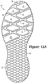
Figures 12A-12C are bottom plan views depicting further configurations of the sole structure, corresponding withFigure 5 . -
Figures 13A-13C are cross-sectional views depicting additional configurations of the sole structure, corresponding withFigure 6A . -
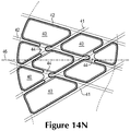
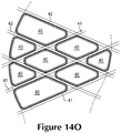
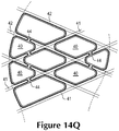
Figures 14A-14Q are bottom plan views depicting further configurations of the chambers, corresponding withFigure 8 . -
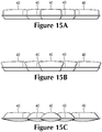
Figures 15A-15C are medial side elevational views depicting additional configurations of the chambers, corresponding withFigure 10 . - The following discussion and accompanying Figures disclose various configurations of fluid-filled chambers. Although the chambers are disclosed with reference to footwear having a configuration that is suitable for running, concepts associated with the chambers may be applied to a wide range of athletic footwear styles, including basketball shoes, cross-training shoes, football shoes, golf shoes, hiking shoes and boots, ski and snowboarding boots, soccer shoes, tennis shoes, and walking shoes, for example. Concepts associated with the chambers may also be utilized with footwear styles that are generally considered to be non-athletic, including dress shoes, loafers, and sandals.
- An article of
footwear 10 is depicted inFigures 1 and2 as including an upper 20 and asole structure 30. For reference purposes,footwear 10 may be divided into three general regions: aforefoot region 11, amidfoot region 12, and aheel region 13, as shown inFigures 1 and2 .Footwear 10 also includes alateral side 14 and amedial side 15.Forefoot region 11 generally includes portions offootwear 10 corresponding with the toes and the joints connecting the metatarsals with the phalanges,Midfoot region 12 generally includes portions offootwear 10 corresponding with the arch area of the foot.Heel region 13 generally includes portions offootwear 10 corresponding with rear portions of the foot, including the calcaneus bone.Lateral side 14 andmedial side 15 extend through each of regions 11-13 and correspond with opposite sides offootwear 10. Regions 11-13 and sides 14-15 are not intended to demarcate precise areas offootwear 10. Rather, regions 11-13 and sides 14-15 are intended to represent general areas offootwear 10 to aid in the following discussion. In addition tofootwear 10, regions 11-13 and sides 14-15 may also be discussed with respect to the foot itself, upper 20,sole structure 30, and individual elements thereof. -
Upper 20 is depicted as having a substantially conventional configuration incorporating a variety of material elements (e.g., textile, foam, leather, and synthetic leather) that are stitched or adhesively bonded together to form an interior void for securely and comfortably receiving a foot. The material elements may be selected and located with respect to upper 20 in order to selectively impart properties of durability, air-permeability, wear-resistance, flexibility, and comfort, for example. Anankle opening 21 inheel region 13 provides access to the interior void. In addition, upper 20 may include alace 22 that is utilized in a conventional manner to modify the dimensions of the interior void, thereby securing the foot within the interior void and facilitating entry and removal of the foot from the interior void.Lace 22 may extend through apertures in upper 20, and a tongue portion of upper 20 may extend between the interior void andlace 22. Given that various aspects of the present application primarily relate tosole structure 30, upper 20 may exhibit the general configuration discussed above or the general configuration of practically any other conventional or nonconventional upper. Accordingly, the overall structure of upper 20 may vary significantly. -
Sole structure 30 is secured to upper 20 and has a configuration that extends between upper 20 and the ground. In effect, therefore,sole structure 30 is located to extend between the foot and the ground. In addition to attenuating ground reaction forces (i.e., providing cushioning for the foot),sole structure 30 may provide traction, impart stability, and limit various foot motions, such as pronation. - An initial configuration of
sole structure 30, includingmidsole 31,outsole 32, andchambers 40, is depicted inFigures 3-10 . The primary elements ofsole structure 30 are amidsole 31, anoutsole 32, and a plurality of fluid-filledchambers 40.Sole structure 30 may also incorporate an insole or sockliner that is located with in the void in upper 20 and adjacent a plantar (i.e., lower) surface of the foot to enhance the comfort offootwear 10. -
Midsole 31 has anupper surface 33 positioned adjacent upper 20.Midsole 31 also has alower surface 34 positionedadjacent outsole 32.Lower surface 34 defines a plurality ofcavities 35 inmidsole 31.Midsole 31 may include a polymer foam material, such as polyurethane or ethylvinylacetate.Midsole 31 may also incorporate one or more additional footwear elements that enhance the comfort, performance, or ground reaction force attenuation properties offootwear 10, including, plates, moderators, lasting elements, or motion control members. -
Outsole 32, which may be partially or entirely absent in some configurations offootwear 10, is secured tolower surface 34 ofmidsole 31.Outsole 32 may form at least part of ground-contactingsurface 38 ofsole structure 30.Outsole 32 defines a plurality ofapertures 36 aligned withcavities 35.Outsole 32 may be formed from a rubber material that provides a durable and wear-resistant surface for engaging the ground. In addition,outsole 32 may also be textured to enhance the traction (i.e., friction) properties betweenfootwear 10 and the ground. In some configurations in which outsole 32 may be partially or entirely absent,midsole 31 may form at least part of a ground-contactingsurface 38 ofsole structure 30. - In the initial configuration, each of
cavities 35 is formed distinctly from the others. In other configurations, two or more ofcavities 35 may be formed to be interconnected with each other. Similarly, in the initial configuration, each ofapertures 36 is formed distinctly from the others. In other configurations, two or more ofapertures 36 may be formed to be interconnected with each other. - A plurality of fluid-filled
chambers 40 extends betweenlateral side 14 andmedial side 15 ofsole structure 30 and is substantially located inforefoot region 11 and portions ofmidfoot region 12 ofsole structure 30.Chambers 40 are at least partially located withincavities 35 and protrude outward fromcavities 35.Chambers 40 extend intoapertures 36. Accordingly,chambers 40 may also form part of ground-contactingsurface 38. A top portion of each ofchambers 40 has an inwardly-angled shape, and a bottom portion of each ofchambers 40 has a substantially rectangular shape. - Some
chambers 40 may be substantially diamond-shaped and may have obtuse angles and acute angles. As such, somechambers 40 are substantially equally spaced from each other and have edges that are substantially parallel with each other, and a distance between twosuch chambers 40 may be substantially constant along the nearest edges of the chambers. For example, in the initial configuration, thevarious chambers 40 located in a central area of sole structure 30 (i.e., in the area centrally-located betweensides 14 and 15) and spaced inward fromsides chamber 40 has two obtuse angles (pointing towardforefoot region 11 and heel region 13) and two acute angles (pointing towardlateral side 14 and medial side 15). Other chambers may have other shapes. For example, in the initial configuration, thechambers 40 located adjacent tosides truncated chamber 40 located adjacent tosides lateral side 14 or medial side 15), and may have one or two obtuse angles (pointing towardforefoot region 11 and heel region 13). - A
sidewall surface 39 ofsole structure 30 extends betweenupper surface 33 ofmidsole 31 and ground-contactingsurface 38. Part ofsidewall surface 39 onlateral side 14 is formed by thechamber 40 adjacent to the lateral side, and part ofsidewall surface 39 onmedial side 15 is formed by thechamber 40 adjacent to the medial side. An advantage ofchambers 40 forming part ofsidewall surface 39 is that characteristics ofchambers 40 such as their presence, extent, placement, or configuration may be visible on an exterior offootwear 10. - In the initial configuration, the plurality of
chambers 40 includes three centrally-located and inwardly-spacedchambers 40, fourchambers 40 adjacent tolateral side 14, and onechamber 40 adjacent tolateral side 15. In further configurations, the plurality ofchambers 40 may include any number of centrally-located and inwardly-spacedchambers 40, and any number ofchambers 40 adjacent tosides - The plurality of
chambers 40 may have a configuration of an array having a number of rows N and a number of columns M, implying positions for a number of chambers N x M. For example, in an initial configuration, the array ofchambers 40 may have a configuration of an arrangement of three rows and three columns, implying positions for nine chambers 40 (eight of which coincide with the extent of the sole structure, the ninth implied position being outside the footprint of footwear 10). Other configurations of arrays ofchambers 40 may imply positions formore chambers 40 or forfewer chambers 40 than in the initial configuration. Additionally, the array ofchambers 40 may imply positions formore chambers 40 or forfewer chambers 40 than are actually in the array ofchambers 40. - A plurality of
first bounding regions 41 and a plurality ofsecond bounding regions 42 are also defined withinsole structure 30. Boundingregions sole structure 30 separatingchambers 40 and adjacent tochambers 40. First boundingregions 41 are substantially straight and parallel with each other, andsecond bounding regions 42 are substantially straight and parallel with each other. Boundingregions midsole 31, such as polymer foam portions.Chambers 40 are at least partially bounded by boundingregions chambers 40, may be entirely bounded by boundingregions sides regions linear bounding regions chamber 40 is bounded by boundingregions - Bounding
regions mediolateral axis 46 offootwear 10.Mediolateral axis 46 extends betweensides regions 41 may be oriented at a first angle with respect tomediolateral axis 46 offootwear 10, andsecond bounding regions 42 may be oriented at a second angle with respect tomediolateral axis 46. That is,first bounding regions 41 may be oriented to face one portion offootwear 10, such aslateral side 14 offorefoot region 11, andsecond bounding regions 42 may be oriented to face a second portion offootwear 10, such asmedial side 15 offorefoot region 11. For example, in the initial configuration,first bounding regions 41 are oriented at a first angle of about 30 degrees with respect tomediolateral axis 46 offootwear 10, andsecond bounding regions 42 are oriented at a second angle of about 30 degrees with respect tomediolateral axis 46, such that the total angle between boundingregions - First bounding
regions 41 meetsecond bounding regions 42 atintersections 43.Intersections 43 may have one or two obtuse angles, oriented to faceforefoot region 11 orheel region 13. Similarly,intersections 43 may have one or two acute angles, oriented to facelateral side 14 ormedial side 15. - Some physical properties of bounding
regions chambers 40. For example, boundingregions chambers 40. As a result,sole structure 30 may stretch, compress, bend, or flex differently at boundingregions chambers 40. An advantage of such a configuration ofchambers 40 and boundingregions sole structure 30 may have some physical properties, such as ground reaction force attenuation properties, related tochambers 40, as well as other physical properties related to boundingregions chambers 40. A further advantage of such a configuration ofchambers 40 and boundingregions sole structure 30 may have a multi-directional flexibility. In other words,sole structure 30 may be relatively more flexible in directions associated with and running normal to or perpendicular to boundingregions regions mediolateral axis 46,sole structure 30 may have a preferential flexibility in more than one direction. -
Outsole 32 may have a plurality of flexion lines 37.Flexion lines 37 may be substantially straight linear indentations extending upward from a bottom surface offootwear 10 in a rubber material ofoutsole 32, and may extend betweenlateral side 14 andmedial side 15.Outsole 32 may bend or flex more easily atflexion lines 37 than at other positions. In some embodiments,flexion lines 37 may, in turn, be aligned with boundingregions chambers 40 may be substantially parallel to a first portion offlexion lines 37, such as a portion offlexion lines 37 facinglateral side 14 offorefoot region 11. Similarly, some edges of the shapes ofchambers 40 may be substantially parallel to a second portion offlexion lines 37, such as a portion offlexion lines 37 facingmedial side 15 offorefoot region 11. -
Chambers 40 are connected by a plurality ofconnections 44. In the initial configuration,chambers 40 are connected to each other by a minimally sufficient number of connections, each of which is substantially parallel tomediolateral axis 46 offootwear 10. In further embodiments, one or more ofchambers 40 may be in fluid connection with each other throughconnections 44. In other embodiments,chambers 40 andconnections 44 may be formed as parts of a single polymer element. -
Chambers 40 may be manufactured through a variety of manufacturing techniques, including blowmolding, thermoforming, and rotational molding, for example. The manufacturing process (a) imparts shape to one polymer sheet in order to form an upper portion ofchambers 40, and (b) imparts shape to the other polymer sheet in order to form a lower portion ofchambers 40. With regard to the blowmolding technique, thermoplastic material is placed in a mold having the general shape ofchambers 40 and pressurized air is utilized to induce the material to coat surfaces of the mold. In the thermoforming technique, layers of thermoplastic material are placed between corresponding portions of a mold, and the mold is utilized to compress the layers together at peripheral locations ofchambers 40. A positive pressure may be applied between the layers of thermoplastic material to induce the layers into the contours of the mold. In addition, a vacuum may be induced in the area between the layers and the mold to draw the layers into the contours of the mold. In the rotational molding technique, thermoplastic material is placed in a mold that subsequently rotates to induce the thermoplastic material to coat surfaces of the mold. Additionally, a process disclosed inU.S. Patent Application Serial Number 12/630,695chambers 40, such application being incorporated herein by reference. - Each of
chambers 40 has a generally hollow configuration that encloses a fluid (e.g., a gas, liquid, gel). Bonds may extend aroundchambers 40 to prevent the fluid from escapingchambers 40 or passing betweenchambers 40, thereby isolating thevarious chambers 40 from fluid communication with each other. In other configurations, conduits extending between chambers 40 (e.g., through connections 44) may placechambers 40 in fluid communication with each other. The fluid withinchambers 40 may be pressurized between zero and three-hundred-fifty kilopascals (i.e., approximately fifty-one pounds per square inch) or more. In addition to air and nitrogen, the fluid may include any of the gasses disclosed inU.S. Patent Number 4,340,626 to Rudy . - Various polymer materials may be utilized for
chambers 40. In selecting a material forchambers 40, the ability of the material to prevent the diffusion of the fluid contained by each ofchambers 40 may be considered, as well as the engineering properties of the material (e.g., tensile strength, stretch properties, fatigue characteristics, dynamic modulus, and loss tangent). Examples of thermoplastic polymer materials that may be suitable forchambers 40 include urethane, polyurethane, polyester, polyester polyurethane, and polyether polyurethane. Various thermoset polymer materials may also be utilized forchambers 40. More specific examples of materials that may be utilized forchambers 40 include the various materials disclosed in any of (a)U.S. Patent Numbers 4,183,156 ,4,219,945 ,4,936,029 , and5,042,176 to Rudy ; (b)U.S. Patent Numbers 5,713,141 and5,952,065 to Mitchell, et al. ; and (c)U.S. Patent Numbers 6,013,340 ,6,082,025 ,6,127,026 ,6,203,868 , and6,321,465 to Bonk, et al . - Additionally, in some configurations, any of
chambers 40 may include any of a range of tensile members, such as the tensile members disclosed inU.S. andPatent Application Number 12/123,612 to DuaU.S. Moreover, in some configurations, any ofPatent Application Number 12/123,646 to Rapaport, et ai.chambers 40 may include any of a range of tether elements, such as the tether elements disclosed inU.S. Patent andApplication Serial Number 12/630,642 to PeytonU.S. Patent . Furthermore, in some configurations, any ofApplication Serial Number 12/777,167 to Peytonchambers 40 may include any of a range of foam tensile members, such as the foam tensile members disclosed inU.S. Patent Number 7,131,218 to Schindler ,U.S. Patent Number 7,588,654 to Schindler et al. , andU.S. Patent Number 7,591,919 to Schindler et al. -
Sole structure 30 incorporatingchambers 40 may have other configurations. In the initial configuration ofsole structure 30,lower surface 34 ofmidsole 31 defines a plurality ofcavities 35. In further configurations,cavities 35 may be defined by other portions ofmidsole 31. For example, with reference toFigure 11A , a plurality ofcavities 35 may be formed within an interior portion ofmidsole 31 betweenupper surface 33 andlower surface 34. Alternatively,upper surface 33 ofmidsole 31 may define a plurality ofcavities 35. In other configurations,cavities 35 may be partially defined by or formed within any combination ofupper surface 33,lower surface 34, or an interior portion ofmidsole 31. - In the initial configuration,
outsole 32 defines a plurality ofapertures 36 aligned withcavities 35. In further configurations,apertures 36 may be absent fromoutsole 32. For example, with reference toFigures 11A and11B ,outsole 32 may not define a plurality ofapertures 36, but may instead extend over and coverchambers 40 withincavities 35 inmidsole 31. In other configurations,outsole 32 may be absent from regions ofsole structure 30 through whichchambers 40 extend. Alternatively, in some configurations, outsole members (i.e., portions of outsole 32) may extend over and cover portions of the lower surfaces ofchambers 40. In such configurations, a portion of the lower surface of one or more ofchambers 40 may be positioned adjacent to a portion ofoutsole 32. That is, one or more ofchambers 40 may be at least partially covered by pieces ofoutsole 32. - In some configurations of
sole structure 30,outsole 32 may be formed of a substantially opaque rubber material. In other configurations,outsole 32 may include an at least partiallytransparent portion 45. For example, with reference toFigure 11B ,outsole 32 may include a substantially clear rubber portion beneath and adjacent tocavities 35,chambers 40, andconnections 44. Partiallytransparent portion 45 may extend through a portion offorefoot region 11 ofoutsole 32, or any other portion or portions ofoutsole 32. - In the initial configuration, part of
sidewall surface 39 onlateral side 14 is formed by thechamber 40 adjacent to the lateral side, and part ofsidewall surface 39 onmedial side 15 is formed by thechamber 40 adjacent to the medial side. In other configurations,chambers 40 may form part ofsidewall surface 39 on onlylateral side 14, or may form part ofsidewall surface 39 only onmedial side 15, or may not form any part ofsidewall surface 39. - In the initial configuration of
sole structure 30,outsole 32 includes a plurality offlexion lines 37 that are substantially straight and linear, are aligned with or substantially parallel to some edges ofchambers 40, and extend betweenlateral side 14 andmedial side 15. In other configurations,outsole 32 may include flexion lines having alternate configurations, or no flexion lines at all. For example, with reference toFigure 11C ,outsole 32 may not include any flexion lines. In some alternate configurations,outsole 32 may include flexion lines that are not substantially straight, such as flexion lines that include curves or angles, or may include flexion lines that do not extend betweenlateral side 14 and media!side 15, such as flexion lines that span only a portion of the distance betweenlateral side 14 andmedial side 15. In other alternate configurations, flexion lines may not be substantially parallel to some edges ofchambers 40, but may instead be perpendicular to edges ofchambers 40, or may meet edges ofchambers 40 at substantially consistent angles overoutsole 32, or may have no relationship at all with edges ofchambers 40. In yet other alternate configurations,outsole 32 may include only flexion lines that are substantially parallel withfirst bounding regions 41, or only flexion lines that are substantially parallel withsecond bounding regions 42. - In the initial configuration,
first bounding regions 41 andsecond bounding regions 42 may be formed of and include portions ofmidsole 31, such as polymer foam portions. In further configurations, boundingregions outsole 32, such as rubber portions. Alternatively, boundingregions chambers 40, such as a gap betweenchambers 40 from which polymer foam material is absent. - In the initial configuration,
chambers 40 extend betweenlateral side 14 andmedial side 15 and are substantially located inforefoot region 11 and portions ofmidfoot region 12 ofsole structure 30. In further configurations,chambers 40 may extend across any portion or portions ofsole structure 30. For example, with reference toFigure 12A ,chambers 40 extend acrosssole structure 30 further than in the initial configuration, in both the direction of the forefoot and the direction of the heel. In another example, with reference toFigure 12B ,chambers 40 extend betweenlateral side 14 andmedial side 15 and are substantially located inheel region 13 ofsole structure 30. In a further example, with reference toFigure 12C ,chambers 40 extend betweenlateral side 14 andmedial side 15, and betweenforefoot region 11 andheel region 13, or across substantially all ofsole structure 30. - In the initial configuration,
chambers 40 protrude outward fromcavities 35 and extend intoapertures 36 inoutsole 32. In further configurations,chambers 40 may have an alternate extent. For example, with reference toFigure 13A , in some configurations,chambers 40 may not protrude outward fromcavities 35 or extend intoapertures 36 inoutsole 32. In another example, with reference toFigure 13B ,chambers 40 may be recessed withincavities 35. In a further example, with reference toFigure 13C ,chambers 40 may protrude outward fromcavities 35 and also protrude outward fromapertures 36 inoutsole 32. As discussed above, in such configurations, one or more ofchambers 40 may be at least partially covered by pieces ofoutsole 32. For example,chambers 40 of the configuration depicted inFigure 13C may be partially covered by pieces ofoutsole 32. - In the initial configuration, a centrally-located and inwardly-spaced portion of
chambers 40 are substantially diamond-shaped. In further configurations, a centrally-located and inwardly-spaced portion ofchambers 40 may have other shapes. In such configurations,chambers 40 may also be partially bounded by boundingregions Figures 14A-14D ,chambers 40 may have substantially hexagonal shapes, substantially octagonal shapes, substantially circular shapes, or substantially elongated or elliptical shapes.Chambers 40 may have any shape, regular or irregular. For example, with reference toFigure 14E ,chambers 40 may have an irregular shape including lobes and indentations. - In the initial configuration, each of a centrally-located and inwardly-spaced portion of
chambers 40 is entirely bounded by boundingregions chamber 40 is bounded by boundingregions chambers 40 may be bounded on fewer than all sides by boundingregions chamber 40 might be bounded by boundingregions Figure 14F , centrally-located and inwardly-spacedchambers 40 may have a configuration of sets of two triangles positioned between boundingregions Figure 14G , centrally-located and inwardly-spacedchambers 40 may have a configuration of sets of two trapezoids positioned between boundingregions Figure 14H , centrally-located and inwardly-spacedchambers 40 may have a configuration of sets of four triangles positioned between boundingregions - In the initial configuration, a majority of the perimeter of each
chamber 40 abuts or is immediately adjacent to substantiallylinear bounding regions chamber 40 abuts or is immediately adjacent to boundingregions Figure 14H , less than a majority of eachchamber 40 abuts or is immediately adjacent to boundingregions Figure 14E , each centrally-located and inwardly-spacedchamber 40 abuts or is immediately adjacent to boundingregions chamber 40. - In the initial configuration,
first bounding regions 41 are substantially straight and parallel with each other, andsecond bounding regions 42 are substantially straight and parallel with each other. In other configurations, either or both offirst bounding regions 41 orsecond bounding regions 42 may not be substantially straight or may not be substantially parallel with each other. For example, with reference toFigure 14I , first boundingregions 41 are substantially curvilinear and parallel with each other, andsecond bounding regions 42 are substantially curvilinear and parallel with each other. Alternatively, with reference toFigure 14J , first boundingregions 41 are substantially straight, but are not parallel with each other, and have a configuration of line portions radiating from and about a point outside oflateral side 14 offootwear 10. Similarly,second bounding regions 42 are substantially straight, but not parallel with each other, and have a configuration of line portions radiating from and about a point outside ofmedial side 15 offootwear 10. In a further example, with reference toFigure 14K , boundingregions regions 41 have a configuration of line portions radiating from and about a point outside oflateral side 14, andsecond bounding regions 42 have a configuration of line portions radiating from and about a point outside ofmedial side 15. - In the initial configuration,
first bounding regions 41 are oriented at a first angle of about 30 degrees with respect tomediolateral axis 46 offootwear 10, andsecond bounding regions 42 are oriented at a second angle of about 30 degrees with respect tomediolateral axis 46, such that the total angle between boundingregions regions mediolateral axis 46. In further configurations, boundingregions mediolateral axis 46. For example, inFigure 14L , the total angle between boundingregions Figure 14M , the total angle between boundingregions Figure 14N , boundingregions mediolateral axis 46. - In the initial configuration,
chambers 40 are connected to each other by a minimally sufficient number ofconnections 44. In other configurations,connections 44 may be otherwise connected or even absent. For example, inFigure 14O ,chambers 40 are not connected to each other at all. Alternatively, inFigure 14P , each ofchambers 40 is connected to each of the nearestother chambers 40 at the corners ofchambers 40. - In the initial configuration,
chambers 40 are connected to each other byconnections 44, each of which is substantially parallel tomediolateral axis 46 offootwear 10. In other configurations,connections 44 may be otherwise oriented. For example, inFigure 14Q ,chambers 40 may be connected to each other byconnections 44, each of which is substantially perpendicular to the boundingregion - In the initial configuration, a top portion of each of
chambers 40 has an inwardly-angled shape, and a bottom portion of each ofchambers 40 has a substantially rectangular shape. In other configurations, the top portions and bottom portions ofchambers 40 may have any other shape, regular or irregular, or any combination of shapes. For example, inFigure 15A , a top portion of each ofchambers 40 is substantially vertical. Alternatively, inFigure 15B , a top portion of each ofchambers 40 has an outwardly-angled shape. In a further example, inFigure 15C , a bottom portion of each ofchambers 40 has a substantially rounded shape. - The invention is disclosed above and in the accompanying figures with reference to a variety of configurations. The purpose served by the disclosure, however, is to provide an example of various features and concepts related to the invention, not to limit the scope of the invention. One skilled in the relevant art will recognize that numerous variations and modifications may be made to the configurations described above without departing from the scope of the present invention, as defined by the appended claims.
- The invention may also be described as set out in the following numbered clauses.
- [Clause 1] An article of footwear having an upper and a sole structure secured to the upper, the sole structure comprising:
- a midsole having an upper surface and a lower surface, the upper surface positioned adjacent to the upper, and the lower surface defining a plurality of cavities; and
- a plurality of fluid-filled chambers at least partially located within the cavities, at least some of the chambers having a diamond shape.
- [Clause 2] The article of footwear of
clause 1, wherein the sole structure further comprises an outsole secured to the midsole, the outsole forming at least part of a ground-contacting surface of the footwear, and the outsole forming a plurality of apertures, each of the plurality of apertures being aligned with one of the plurality of cavities. - [Clause 3] The article of footwear of clause 2, wherein the chambers form at least part of the ground-contacting surface.
- [Clause 4] The article of footwear of clause 2, wherein the outsole includes an at least partially transparent portion located adjacent at least some of the chambers.
- [Clause 5] The article of footwear of clause 2, wherein the outsole includes a plurality of first flexion lines and a plurality of second flexion lines, at least some edges of the diamond shapes of the chambers being substantially parallel to the first flexion lines, and at least some edges of the diamond shapes of the chambers being substantially parallel to the second flexion lines.
- [Clause 6] The article of footwear of
clause 1, wherein the sole structure further comprises a sidewall extending between the upper surface of the midsole and a ground-contacting surface of the footwear, at least part of the sidewall being formed by a surface of at least one of the chambers. - [Clause 7] The article of footwear of
clause 1, wherein a majority of the chambers are substantially located in a forefoot region of the footwear. - [Clause 8] The article of footwear of
clause 1, wherein the sole structure further comprises a plurality of connections between the chambers. - [Clause 9] An article of footwear having an upper and a sole structure secured to the upper, the sole structure comprising:
- a midsole having an upper surface and a lower surface, the upper surface positioned adjacent to the upper, and the lower surface defining an array of cavities;
- an outsole secured to the midsole, the outsole forming at least part of a ground-contacting surface of the footwear; and
- an array of fluid-filled chambers at least partially located within the cavities, the chambers protruding outward from the cavities and forming at least part of a ground-contacting surface of the footwear.
- [Clause 10] The article of footwear of clause 9, wherein the outsole defines an array of apertures, each of the apertures being aligned with one of the cavities, and the chambers extend into the apertures.
- [Clause 11] The article of footwear of
clause 10, wherein the chambers form at least part of an edge surface of the sole structure. - [Clause 12] The article of footwear of clause 9, wherein at least a portion of the chambers has a substantially diamond-shaped configuration.
- [Clause 13] The article of footwear of clause 9, wherein a majority of the chambers are substantially located in a forefoot region of the footwear.
- [Clause 14] The article of footwear of clause 9, wherein the sole structure further comprises a plurality of connections between the chambers.
- [Clause 15] The article of footwear of
clause 14, wherein at least some of the connections are substantially aligned with a mediolateral axis of the footwear. - [Clause 16] An article of footwear having an upper and a sole structure secured to the upper, the sole structure comprising:
- a midsole having an upper surface and a lower surface, the upper surface positioned adjacent to the upper, and the midsole defining a plurality of cavities;
- an outsole secured to the lower surface of the midsole, the outsole forming at least part of a ground-contacting surface of the footwear;
- a plurality of first bounding regions and a plurality of second bounding regions, each intersection of the first bounding regions and the second bounding regions including at least one of an obtuse angle and an acute angle; and
- a plurality of fluid-filled chambers at least partially located within the cavities, the chambers being at least partially bounded by the first bounding regions, and the chambers being at least partially bounded by the second bounding regions.
- [Clause 17] The article of footwear of clause 16, wherein the outsole forms a plurality of apertures, each of the plurality of apertures being aligned with one of the plurality of cavities
- [Clause 18] The article of footwear of clause 17, wherein the chambers protrude outward from the cavities and extend into the apertures.
- [Clause 19] The article of footwear of clause 18, wherein the chambers protrude outward from the cavities, extend into the apertures, and protrude beyond a ground-contacting surface of the outsole.
- [Clause 20] The article of footwear of clause 16, wherein the outsole includes a plurality of flexion lines aligned with the bounding regions.
- [Clause 21] The article of footwear of clause 16, wherein the bounding regions have a configuration of substantially straight lines.
- [Clause 22] The article of footwear of clause 16, wherein the chambers form at least part of the ground-contacting surface of the footwear.
- [Clause 23] The article of footwear of clause 16, wherein at least a portion of the chambers have a substantially diamond-shaped configuration.
- [Clause 24] The article of footwear of clause 16, wherein at least fifty percent of a perimeter of each chamber abuts the bounding regions.
- [Clause 25] The article of footwear of clause 16, wherein the sole structure further comprises a plurality of connections between the chambers.
Claims (15)
- An article of footwear having an upper and a sole structure secured to the upper, the sole structure comprising:a midsole having an upper surface and a lower surface, the upper surface positioned adjacent to the upper, and the lower surface defining an array of cavities;an outsole secured to the midsole and including a first surface that forms at least part of a ground-contacting surface of the article of footwear; andan array of fluid-filled chambers at least partially located within the cavities, the chambers protruding outward from the cavities and including a second surface that is coplanar with the first surface and forms at least part of a ground-contacting surface of the article of footwear.
- The article of footwear of Claim 1, wherein (i) the outsole defines an array of apertures, (ii) each of the apertures are aligned with one of the cavities, and (iii) the chambers extend into the apertures.
- The article of footwear of Claim 2, wherein the chambers form at least part of an edge surface of the sole structure.
- The article of footwear of Claim 2 or Claim 3, wherein each aperture is formed distinctly from the other apertures.
- The article of footwear of any of Claims 2-4, wherein at least one aperture of the array of apertures forms an opening at a perimeter of the outsole.
- The article of footwear of any of the preceding claims, wherein at least one fluid-filled chamber of the array of fluid-filled chambers has a substantially diamond-shaped configuration.
- The article of footwear of any of the preceding claims, wherein a majority of the fluid-filled chambers of the array of fluid-filled chambers are substantially located in a forefoot region of the article of footwear.
- The article of footwear of any of the preceding claims, further comprising a plurality of connections located between the fluid-filled chambers of the array of fluid-filled chambers.
- The article of footwear of Claim 8, wherein at least one of the plurality of connections is substantially aligned with a mediolateral axis of the article of footwear.
- The article of footwear of Claim 8 or Claim 9, wherein at least one of the plurality of connections is disposed between the midsole and the outsole.
- The article of footwear of any of the preceding claims, wherein the array of fluid-filled chambers are bounded by a plurality of first bounding regions and a plurality of second bounding regions, each intersection of the first bounding regions and the second bounding regions including at least one of an obtuse angle and an acute angle.
- The article of footwear of Claim 11, wherein the outsole includes a plurality of flexion lines aligned with the bounding regions.
- The article of footwear of Claim 11 or Claim 12, wherein the bounding regions have a configuration of substantially straight lines.
- The article of footwear of any of Claims 11-13, wherein at least fifty percent of a perimeter of each fluid-filled chamber of the array of fluid-filled chambers abuts the bounding regions.
- The article of footwear of any of the preceding claims, wherein each cavity of the array of cavities includes a similar shape as a fluid-filled chamber of the array of fluid-filled chambers received therein.
Applications Claiming Priority (3)
| Application Number | Priority Date | Filing Date | Title |
|---|---|---|---|
| US13/049,245 US10010136B2 (en) | 2011-03-16 | 2011-03-16 | Footwear sole structure incorporating a plurality of chambers |
| EP12716799.7A EP2685855B1 (en) | 2011-03-16 | 2012-03-07 | Footwear sole structure incorporating a plurality of chambers |
| PCT/US2012/028094 WO2012125372A2 (en) | 2011-03-16 | 2012-03-07 | Footwear sole structure incorporating a plurality of chambers |
Related Parent Applications (2)
| Application Number | Title | Priority Date | Filing Date |
|---|---|---|---|
| EP12716799.7A Division EP2685855B1 (en) | 2011-03-16 | 2012-03-07 | Footwear sole structure incorporating a plurality of chambers |
| EP12716799.7A Division-Into EP2685855B1 (en) | 2011-03-16 | 2012-03-07 | Footwear sole structure incorporating a plurality of chambers |
Publications (2)
| Publication Number | Publication Date |
|---|---|
| EP3430935A1 true EP3430935A1 (en) | 2019-01-23 |
| EP3430935B1 EP3430935B1 (en) | 2022-04-13 |
Family
ID=46001727
Family Applications (2)
| Application Number | Title | Priority Date | Filing Date |
|---|---|---|---|
| EP12716799.7A Active EP2685855B1 (en) | 2011-03-16 | 2012-03-07 | Footwear sole structure incorporating a plurality of chambers |
| EP18194273.1A Active EP3430935B1 (en) | 2011-03-16 | 2012-03-07 | Article of footwear with sole structure incorporating a plurality of chambers |
Family Applications Before (1)
| Application Number | Title | Priority Date | Filing Date |
|---|---|---|---|
| EP12716799.7A Active EP2685855B1 (en) | 2011-03-16 | 2012-03-07 | Footwear sole structure incorporating a plurality of chambers |
Country Status (4)
| Country | Link |
|---|---|
| US (2) | US10010136B2 (en) |
| EP (2) | EP2685855B1 (en) |
| CN (2) | CN103582434B (en) |
| WO (1) | WO2012125372A2 (en) |
Families Citing this family (87)
| Publication number | Priority date | Publication date | Assignee | Title |
|---|---|---|---|---|
| US9297150B2 (en) | 2007-10-24 | 2016-03-29 | Michael Edward Klicpera | Water use monitoring apparatus and water damage prevention system |
| US9913508B2 (en) * | 2011-08-31 | 2018-03-13 | Varithotics Co., Ltd. | Foot balancing device |
| USD712644S1 (en) * | 2011-10-21 | 2014-09-09 | Columbia Sportswear North America, Inc. | Footwear |
| USD677453S1 (en) * | 2011-11-02 | 2013-03-12 | Deckers Outdoor Corporation | Footwear outsole |
| US10034517B2 (en) * | 2011-12-29 | 2018-07-31 | Reebok International Limited | Sole and article of footwear having a pod assembly |
| US9609913B2 (en) | 2011-12-29 | 2017-04-04 | Reebok International Limited | Sole and article of footwear having a pod assemby |
| DE102012206062B4 (en) | 2012-04-13 | 2019-09-12 | Adidas Ag | SHOE UPPER PART |
| USD686406S1 (en) * | 2012-05-10 | 2013-07-23 | Sorel Corporation | Footwear |
| USD712125S1 (en) * | 2012-07-03 | 2014-09-02 | New Balance Athletic Shoe, Inc. | Shoe sole |
| USD683529S1 (en) * | 2012-07-06 | 2013-06-04 | Ariat International, Inc. | Footwear outsole |
| USD671726S1 (en) * | 2012-09-15 | 2012-12-04 | Nike, Inc. | Shoe outsole |
| USD677454S1 (en) * | 2012-10-31 | 2013-03-12 | Nike, Inc. | Shoe outsole |
| USD677455S1 (en) * | 2012-10-31 | 2013-03-12 | Nike, Inc. | Shoe outsole |
| US9981437B2 (en) | 2013-02-21 | 2018-05-29 | Nike, Inc. | Article of footwear with first and second outsole components and method of manufacturing an article of footwear |
| US11666113B2 (en) | 2013-04-19 | 2023-06-06 | Adidas Ag | Shoe with knitted outer sole |
| DE102013207156B4 (en) | 2013-04-19 | 2025-12-24 | Adidas Ag | shoe, especially a sports shoe |
| DE102013207163B4 (en) | 2013-04-19 | 2022-09-22 | Adidas Ag | shoe upper |
| DE102013207155B4 (en) | 2013-04-19 | 2020-04-23 | Adidas Ag | Shoe upper |
| US12250994B2 (en) | 2013-04-19 | 2025-03-18 | Adidas Ag | Shoe |
| US20160157554A1 (en) * | 2013-08-09 | 2016-06-09 | Linear International Footwear Inc. | Air exhaust outsole for safety footwear |
| US20150040425A1 (en) * | 2013-08-09 | 2015-02-12 | Linear International Footwear Inc. | Air exhaust outsole for safety footwear |
| USD704424S1 (en) * | 2013-11-12 | 2014-05-13 | Nike, Inc. | Shoe outsole |
| USD712126S1 (en) * | 2013-11-12 | 2014-09-02 | Nike, Inc. | Shoe outsole |
| USD707935S1 (en) * | 2013-11-12 | 2014-07-01 | Nike, Inc. | Shoe outsole |
| USD701027S1 (en) * | 2013-11-30 | 2014-03-18 | Nike, Inc. | Shoe outsole |
| US9615626B2 (en) * | 2013-12-20 | 2017-04-11 | Nike, Inc. | Sole structure with segmented portions |
| US9955749B2 (en) * | 2014-01-14 | 2018-05-01 | Nike, Inc. | Footwear having sensory feedback outsole |
| DE102014202432B4 (en) | 2014-02-11 | 2017-07-27 | Adidas Ag | Improved football boot |
| US10226906B2 (en) * | 2014-04-14 | 2019-03-12 | Nike, Inc. | Method of manufacturing sole assembly formed of multiple preforms |
| US9687044B2 (en) | 2014-07-24 | 2017-06-27 | Nike, Inc. | Footwear with sole structure incorporating lobed fluid-filled chamber with protruding end wall portions |
| US20160066649A1 (en) * | 2014-09-05 | 2016-03-10 | Skydex Technologies, Inc. | Welded shoe assembly |
| DE102014220087B4 (en) | 2014-10-02 | 2016-05-12 | Adidas Ag | Flat knitted shoe top for sports shoes |
| CN107405851B (en) | 2015-04-21 | 2019-10-22 | 耐克创新有限合伙公司 | Capsule-like element formed from three sheets and method of making a pouch-like element |
| EP3285608B1 (en) * | 2015-04-24 | 2019-05-22 | Nike Innovate C.V. | Footwear sole structure having bladder with integrated outsole |
| USD780420S1 (en) * | 2015-08-14 | 2017-03-07 | Nike, Inc. | Shoe outsole |
| USD778562S1 (en) * | 2015-08-14 | 2017-02-14 | Nike, Inc. | Shoe outsole |
| US9668542B2 (en) * | 2015-08-14 | 2017-06-06 | Nike, Inc. | Sole structure including sipes |
| US10070688B2 (en) * | 2015-08-14 | 2018-09-11 | Nike, Inc. | Sole structures with regionally applied auxetic openings and siping |
| USD783971S1 (en) * | 2015-08-14 | 2017-04-18 | Nike, Inc. | Shoe outsole |
| US9775407B2 (en) | 2015-11-03 | 2017-10-03 | Nike, Inc. | Article of footwear including a bladder element having a cushioning component with a single central opening and method of manufacturing |
| US10070691B2 (en) | 2015-11-03 | 2018-09-11 | Nike, Inc. | Article of footwear including a bladder element having a cushioning component with a single central opening and a cushioning component with multiple connecting features and method of manufacturing |
| US10905194B2 (en) | 2015-11-03 | 2021-02-02 | Nike, Inc. | Sole structure for an article of footwear having a bladder element with laterally extending tubes and method of manufacturing a sole structure |
| GB2544555B (en) * | 2015-11-23 | 2019-10-23 | Fitflop Ltd | An item of footwear |
| US10856610B2 (en) | 2016-01-15 | 2020-12-08 | Hoe-Phuan Ng | Manual and dynamic shoe comfortness adjustment methods |
| US11549837B2 (en) | 2016-02-04 | 2023-01-10 | Michael Edward Klicpera | Water meter and leak detection system |
| JP3221315U (en) * | 2016-03-15 | 2019-05-23 | ナイキ イノヴェイト シーヴィーNike Innovate C.V. | Footwear having first and second outsole components |
| JP6963369B2 (en) * | 2016-09-30 | 2021-11-10 | 美津濃株式会社 | Sole structure for shoes and shoes using it |
| US11752413B2 (en) * | 2016-12-31 | 2023-09-12 | Under Armour, Inc. | Article of footwear with multiple durometer outsole and directional cleat pattern |
| KR102207241B1 (en) * | 2017-02-01 | 2021-01-22 | 나이키 이노베이트 씨.브이. | Stacked cushioning arrangement for sole structure |
| USD848131S1 (en) | 2017-02-01 | 2019-05-14 | Fuerst Group, Inc. | Outsole for a footwear article |
| USD821719S1 (en) * | 2017-02-13 | 2018-07-03 | Nike, Inc. | Shoe outsole |
| CN113598471B (en) | 2017-05-23 | 2022-08-09 | 耐克创新有限合伙公司 | Midsole system with graded response |
| KR102326973B1 (en) | 2017-05-23 | 2021-11-16 | 나이키 이노베이트 씨.브이. | Midsole with graded response |
| EP4140349A1 (en) * | 2017-05-23 | 2023-03-01 | Nike Innovate C.V. | Domed midsole with staged compressive stiffness |
| US10638812B2 (en) * | 2017-05-24 | 2020-05-05 | Nike, Inc. | Flexible sole for article of footwear |
| CN106983224A (en) * | 2017-06-09 | 2017-07-28 | 重庆慧高科技有限公司 | Ventilating shoe soles with heating and dehumidification function |
| CN107087847A (en) * | 2017-06-09 | 2017-08-25 | 重庆慧高科技有限公司 | The ventilative antiskid, shock-absorbing sole of height |
| CN107080326A (en) * | 2017-06-09 | 2017-08-22 | 重庆慧高科技有限公司 | The sole of shoe of comfort level can be improved |
| US11583029B2 (en) * | 2018-01-22 | 2023-02-21 | Adidas Ag | Article of footwear with ribbed outsole and notched midsole |
| US10492564B1 (en) * | 2018-05-14 | 2019-12-03 | Wolverine Outdoors, Inc. | Footwear construction |
| USD872434S1 (en) * | 2018-05-25 | 2020-01-14 | Nike, Inc. | Shoe |
| KR102472834B1 (en) * | 2018-05-30 | 2022-11-30 | 나이키 이노베이트 씨.브이. | Footwear sole structure with bladder |
| USD894571S1 (en) * | 2018-06-01 | 2020-09-01 | Cole Haan Llc | Shoe sole |
| USD893152S1 (en) * | 2018-06-01 | 2020-08-18 | Cole Haan Llc | Shoe sole |
| USD885028S1 (en) * | 2018-07-11 | 2020-05-26 | Zhejiang Huanqiu Shoes Co., Ltd | Shoe sole |
| USD880118S1 (en) * | 2018-07-18 | 2020-04-07 | Converse Inc. | Shoe |
| USD880132S1 (en) * | 2018-07-26 | 2020-04-07 | Converse Inc. | Shoe |
| CN121220849A (en) | 2018-07-31 | 2025-12-30 | 耐克创新有限合伙公司 | Sole structure for footwear |
| CN113056214B (en) | 2018-11-20 | 2022-07-12 | 耐克创新有限合伙公司 | Footwear bladder system |
| CN115413854B (en) | 2018-11-20 | 2026-02-17 | 耐克创新有限合伙公司 | Footwear sac system |
| TWI789574B (en) * | 2019-03-01 | 2023-01-11 | 荷蘭商耐克創新有限合夥公司 | Article of footwear with midfoot flexibility |
| US12171300B2 (en) * | 2019-03-28 | 2024-12-24 | Nike, Inc. | Sole structure of an article of footwear |
| WO2020206428A1 (en) * | 2019-04-04 | 2020-10-08 | The Regents Of The University Of California | Variable friction shoe |
| USD900443S1 (en) * | 2019-05-17 | 2020-11-03 | Nike, Inc. | Shoe |
| USD929710S1 (en) * | 2019-11-13 | 2021-09-07 | Cole Haan Llc | Shoe |
| GB2590068A (en) * | 2019-11-18 | 2021-06-23 | Inoveight Ltd | A shoe sole |
| US11766092B2 (en) | 2020-02-21 | 2023-09-26 | Nike, Inc. | Sole structure for article of footwear |
| USD943259S1 (en) * | 2021-03-01 | 2022-02-15 | Nike, Inc. | Shoe |
| USD949528S1 (en) * | 2021-06-08 | 2022-04-26 | Nike, Inc. | Shoe |
| USD949537S1 (en) * | 2021-06-08 | 2022-04-26 | Nike, Inc. | Shoe |
| WO2023067439A1 (en) | 2021-10-18 | 2023-04-27 | Puma SE | Shoe with foam pods and chassis |
| CN119277970A (en) * | 2022-06-16 | 2025-01-07 | 耐克创新有限合伙公司 | Bags for footwear |
| US12490807B2 (en) * | 2022-06-16 | 2025-12-09 | Nike, Inc. | Bladder for an article of footwear |
| US20240180291A1 (en) * | 2022-12-05 | 2024-06-06 | Reebok International Limited | Article of footwear having a reflectively symmetrical fluid cushioning system |
| USD1079224S1 (en) * | 2023-06-02 | 2025-06-17 | Nike, Inc. | Shoe |
| US12604945B2 (en) | 2023-06-15 | 2026-04-21 | Nike, Inc. | Bladder for an article of footwear |
| USD1039792S1 (en) * | 2023-12-21 | 2024-08-27 | Hongji Lin | Shoe |
Citations (17)
| Publication number | Priority date | Publication date | Assignee | Title |
|---|---|---|---|---|
| US4183156A (en) | 1977-01-14 | 1980-01-15 | Robert C. Bogert | Insole construction for articles of footwear |
| US4219945A (en) | 1978-06-26 | 1980-09-02 | Robert C. Bogert | Footwear |
| US4340626A (en) | 1978-05-05 | 1982-07-20 | Rudy Marion F | Diffusion pumping apparatus self-inflating device |
| US4936029A (en) | 1989-01-19 | 1990-06-26 | R. C. Bogert | Load carrying cushioning device with improved barrier material for control of diffusion pumping |
| US5042176A (en) | 1989-01-19 | 1991-08-27 | Robert C. Bogert | Load carrying cushioning device with improved barrier material for control of diffusion pumping |
| US5367791A (en) * | 1993-02-04 | 1994-11-29 | Asahi, Inc. | Shoe sole |
| US5713141A (en) | 1994-08-31 | 1998-02-03 | Nike, Inc. | Cushioning device with improved flexible barrier membrane |
| US6009637A (en) * | 1998-03-02 | 2000-01-04 | Pavone; Luigi Alessio | Helium footwear sole |
| US6013340A (en) | 1995-06-07 | 2000-01-11 | Nike, Inc. | Membranes of polyurethane based materials including polyester polyols |
| US6082025A (en) | 1998-09-11 | 2000-07-04 | Nike, Inc. | Flexible membranes |
| US6127026A (en) | 1998-09-11 | 2000-10-03 | Nike, Inc. | Flexible membranes |
| US6321465B1 (en) | 1995-06-07 | 2001-11-27 | Nike, Inc. | Membranes of polyurethane based materials including polyester polyols |
| US7131218B2 (en) | 2004-02-23 | 2006-11-07 | Nike, Inc. | Fluid-filled bladder incorporating a foam tensile member |
| US20090126230A1 (en) * | 2004-06-04 | 2009-05-21 | Nike, Inc. | Article Of Footwear With Outsole Web and Midsole Protrusions |
| US20090199430A1 (en) * | 2008-02-08 | 2009-08-13 | Montross Matt | Multi-Chamber Cushion For Footwear |
| US7588654B2 (en) | 2007-08-13 | 2009-09-15 | Nike, Inc. | Fluid-filled chambers with foam tensile members and methods for manufacturing the chambers |
| US7591919B2 (en) | 2007-08-13 | 2009-09-22 | Nike, Inc. | Fluid-filled chambers with foam tensile members and methods for manufacturing the chambers |
Family Cites Families (27)
| Publication number | Priority date | Publication date | Assignee | Title |
|---|---|---|---|---|
| CA2041623A1 (en) * | 1990-05-07 | 1991-11-08 | Bruce J. Kilgore | Shoe and sole structure with fluid filled inserts |
| US5771606A (en) * | 1994-10-14 | 1998-06-30 | Reebok International Ltd. | Support and cushioning system for an article of footwear |
| US6453577B1 (en) | 1996-02-09 | 2002-09-24 | Reebok International Ltd. | Support and cushioning system for an article of footwear |
| US5771611A (en) | 1996-06-20 | 1998-06-30 | Shuang-Bang Industrial Corporation | Transparent, lighted sole construction |
| US5799417A (en) * | 1997-01-13 | 1998-09-01 | Bata Limited | Shoe sole with removal insert |
| US7000334B2 (en) * | 2001-02-16 | 2006-02-21 | Srl, Inc. | Shoe outsole |
| US6915596B2 (en) | 2003-01-21 | 2005-07-12 | Nike, Inc. | Footwear with separable upper and sole structure |
| US7000335B2 (en) * | 2003-07-16 | 2006-02-21 | Nike, Inc. | Footwear with a sole structure incorporating a lobed fluid-filled chamber |
| US20050115107A1 (en) | 2003-12-01 | 2005-06-02 | Schumacher James H. | Flexible outsole |
| US7562469B2 (en) * | 2003-12-23 | 2009-07-21 | Nike, Inc. | Footwear with fluid-filled bladder and a reinforcing structure |
| US7200955B2 (en) * | 2004-06-04 | 2007-04-10 | Nike, Inc. | Article of footwear incorporating a sole structure with compressible inserts |
| US8146272B2 (en) | 2008-05-30 | 2012-04-03 | Nike, Inc. | Outsole having grooves forming discrete lugs |
| US7533477B2 (en) * | 2005-10-03 | 2009-05-19 | Nike, Inc. | Article of footwear with a sole structure having fluid-filled support elements |
| US7752772B2 (en) * | 2006-01-24 | 2010-07-13 | Nike, Inc. | Article of footwear having a fluid-filled chamber with flexion zones |
| US7797856B2 (en) * | 2007-04-10 | 2010-09-21 | Reebok International Ltd. | Lightweight sole for article of footwear |
| US7950169B2 (en) * | 2007-05-10 | 2011-05-31 | Nike, Inc. | Contoured fluid-filled chamber |
| US7941941B2 (en) * | 2007-07-13 | 2011-05-17 | Nike, Inc. | Article of footwear incorporating foam-filled elements and methods for manufacturing the foam-filled elements |
| US8151486B2 (en) | 2008-05-20 | 2012-04-10 | Nike, Inc. | Fluid-filled chamber with a textile tensile member |
| US8241451B2 (en) | 2008-05-20 | 2012-08-14 | Nike, Inc. | Contoured fluid-filled chamber with a tensile member |
| US8424221B2 (en) * | 2009-04-01 | 2013-04-23 | Reebok International Limited | Training footwear |
| US8479412B2 (en) | 2009-12-03 | 2013-07-09 | Nike, Inc. | Tethered fluid-filled chambers |
| US9119439B2 (en) | 2009-12-03 | 2015-09-01 | Nike, Inc. | Fluid-filled structure |
| USD677453S1 (en) * | 2011-11-02 | 2013-03-12 | Deckers Outdoor Corporation | Footwear outsole |
| USD686406S1 (en) * | 2012-05-10 | 2013-07-23 | Sorel Corporation | Footwear |
| US10058144B2 (en) * | 2014-08-06 | 2018-08-28 | Nike, Inc. | Article of footwear with midsole with arcuate underside cavity |
| US10945850B2 (en) | 2018-10-25 | 2021-03-16 | Revision Technologies Llc | Interconnected implants and methods |
| US12361208B2 (en) | 2018-12-19 | 2025-07-15 | Fivecast Pty Ltd | Method and system for identifying and visualizing data differences between data sets |
-
2011
- 2011-03-16 US US13/049,245 patent/US10010136B2/en active Active
-
2012
- 2012-03-07 EP EP12716799.7A patent/EP2685855B1/en active Active
- 2012-03-07 CN CN201280013190.XA patent/CN103582434B/en active Active
- 2012-03-07 WO PCT/US2012/028094 patent/WO2012125372A2/en not_active Ceased
- 2012-03-07 CN CN201610243764.2A patent/CN105831877B/en active Active
- 2012-03-07 EP EP18194273.1A patent/EP3430935B1/en active Active
-
2018
- 2018-05-23 US US15/987,060 patent/US12207699B2/en active Active
Patent Citations (20)
| Publication number | Priority date | Publication date | Assignee | Title |
|---|---|---|---|---|
| US4183156A (en) | 1977-01-14 | 1980-01-15 | Robert C. Bogert | Insole construction for articles of footwear |
| US4340626A (en) | 1978-05-05 | 1982-07-20 | Rudy Marion F | Diffusion pumping apparatus self-inflating device |
| US4219945A (en) | 1978-06-26 | 1980-09-02 | Robert C. Bogert | Footwear |
| US4219945B1 (en) | 1978-06-26 | 1993-10-19 | Robert C. Bogert | Footwear |
| US4936029A (en) | 1989-01-19 | 1990-06-26 | R. C. Bogert | Load carrying cushioning device with improved barrier material for control of diffusion pumping |
| US5042176A (en) | 1989-01-19 | 1991-08-27 | Robert C. Bogert | Load carrying cushioning device with improved barrier material for control of diffusion pumping |
| US5367791A (en) * | 1993-02-04 | 1994-11-29 | Asahi, Inc. | Shoe sole |
| US5713141A (en) | 1994-08-31 | 1998-02-03 | Nike, Inc. | Cushioning device with improved flexible barrier membrane |
| US5952065A (en) | 1994-08-31 | 1999-09-14 | Nike, Inc. | Cushioning device with improved flexible barrier membrane |
| US6013340A (en) | 1995-06-07 | 2000-01-11 | Nike, Inc. | Membranes of polyurethane based materials including polyester polyols |
| US6203868B1 (en) | 1995-06-07 | 2001-03-20 | Nike, Inc. | Barrier members including a barrier layer employing polyester polyols |
| US6321465B1 (en) | 1995-06-07 | 2001-11-27 | Nike, Inc. | Membranes of polyurethane based materials including polyester polyols |
| US6009637A (en) * | 1998-03-02 | 2000-01-04 | Pavone; Luigi Alessio | Helium footwear sole |
| US6082025A (en) | 1998-09-11 | 2000-07-04 | Nike, Inc. | Flexible membranes |
| US6127026A (en) | 1998-09-11 | 2000-10-03 | Nike, Inc. | Flexible membranes |
| US7131218B2 (en) | 2004-02-23 | 2006-11-07 | Nike, Inc. | Fluid-filled bladder incorporating a foam tensile member |
| US20090126230A1 (en) * | 2004-06-04 | 2009-05-21 | Nike, Inc. | Article Of Footwear With Outsole Web and Midsole Protrusions |
| US7588654B2 (en) | 2007-08-13 | 2009-09-15 | Nike, Inc. | Fluid-filled chambers with foam tensile members and methods for manufacturing the chambers |
| US7591919B2 (en) | 2007-08-13 | 2009-09-22 | Nike, Inc. | Fluid-filled chambers with foam tensile members and methods for manufacturing the chambers |
| US20090199430A1 (en) * | 2008-02-08 | 2009-08-13 | Montross Matt | Multi-Chamber Cushion For Footwear |
Also Published As
| Publication number | Publication date |
|---|---|
| WO2012125372A3 (en) | 2012-11-08 |
| CN103582434A (en) | 2014-02-12 |
| US12207699B2 (en) | 2025-01-28 |
| EP2685855A2 (en) | 2014-01-22 |
| US20180263336A1 (en) | 2018-09-20 |
| CN105831877B (en) | 2018-11-16 |
| WO2012125372A2 (en) | 2012-09-20 |
| EP3430935B1 (en) | 2022-04-13 |
| US20120233885A1 (en) | 2012-09-20 |
| EP2685855B1 (en) | 2018-10-31 |
| CN105831877A (en) | 2016-08-10 |
| CN103582434B (en) | 2016-05-11 |
| US10010136B2 (en) | 2018-07-03 |
Similar Documents
| Publication | Publication Date | Title |
|---|---|---|
| US12207699B2 (en) | Footwear sole structure incorporating a plurality of chambers | |
| US12082652B2 (en) | Article of footwear having a sole structure with perimeter and central chambers | |
| US9044065B2 (en) | Fluid-filled chambers with tether elements | |
| EP2568841B1 (en) | Article of footwear having a sole structure with a framework-chamber arrangement | |
| EP2661974B1 (en) | Interlocking fluid-filled chambers for an article of footwear | |
| HK40030563B (en) | Article of footwear having a sole structure with perimeter and central elements | |
| HK40030563A (en) | Article of footwear having a sole structure with perimeter and central elements |
Legal Events
| Date | Code | Title | Description |
|---|---|---|---|
| PUAI | Public reference made under article 153(3) epc to a published international application that has entered the european phase |
Free format text: ORIGINAL CODE: 0009012 |
|
| STAA | Information on the status of an ep patent application or granted ep patent |
Free format text: STATUS: THE APPLICATION HAS BEEN PUBLISHED |
|
| AC | Divisional application: reference to earlier application |
Ref document number: 2685855 Country of ref document: EP Kind code of ref document: P |
|
| AK | Designated contracting states |
Kind code of ref document: A1 Designated state(s): AL AT BE BG CH CY CZ DE DK EE ES FI FR GB GR HR HU IE IS IT LI LT LU LV MC MK MT NL NO PL PT RO RS SE SI SK SM TR |
|
| STAA | Information on the status of an ep patent application or granted ep patent |
Free format text: STATUS: REQUEST FOR EXAMINATION WAS MADE |
|
| 17P | Request for examination filed |
Effective date: 20190723 |
|
| RBV | Designated contracting states (corrected) |
Designated state(s): AL AT BE BG CH CY CZ DE DK EE ES FI FR GB GR HR HU IE IS IT LI LT LU LV MC MK MT NL NO PL PT RO RS SE SI SK SM TR |
|
| STAA | Information on the status of an ep patent application or granted ep patent |
Free format text: STATUS: EXAMINATION IS IN PROGRESS |
|
| 17Q | First examination report despatched |
Effective date: 20201125 |
|
| GRAP | Despatch of communication of intention to grant a patent |
Free format text: ORIGINAL CODE: EPIDOSNIGR1 |
|
| STAA | Information on the status of an ep patent application or granted ep patent |
Free format text: STATUS: GRANT OF PATENT IS INTENDED |
|
| INTG | Intention to grant announced |
Effective date: 20211027 |
|
| GRAS | Grant fee paid |
Free format text: ORIGINAL CODE: EPIDOSNIGR3 |
|
| GRAA | (expected) grant |
Free format text: ORIGINAL CODE: 0009210 |
|
| STAA | Information on the status of an ep patent application or granted ep patent |
Free format text: STATUS: THE PATENT HAS BEEN GRANTED |
|
| AC | Divisional application: reference to earlier application |
Ref document number: 2685855 Country of ref document: EP Kind code of ref document: P |
|
| AK | Designated contracting states |
Kind code of ref document: B1 Designated state(s): AL AT BE BG CH CY CZ DE DK EE ES FI FR GB GR HR HU IE IS IT LI LT LU LV MC MK MT NL NO PL PT RO RS SE SI SK SM TR |
|
| REG | Reference to a national code |
Ref country code: GB Ref legal event code: FG4D |
|
| REG | Reference to a national code |
Ref country code: CH Ref legal event code: EP |
|
| REG | Reference to a national code |
Ref country code: DE Ref legal event code: R096 Ref document number: 602012078052 Country of ref document: DE |
|
| REG | Reference to a national code |
Ref country code: IE Ref legal event code: FG4D |
|
| REG | Reference to a national code |
Ref country code: AT Ref legal event code: REF Ref document number: 1482706 Country of ref document: AT Kind code of ref document: T Effective date: 20220515 |
|
| REG | Reference to a national code |
Ref country code: LT Ref legal event code: MG9D |
|
| REG | Reference to a national code |
Ref country code: NL Ref legal event code: MP Effective date: 20220413 |
|
| REG | Reference to a national code |
Ref country code: AT Ref legal event code: MK05 Ref document number: 1482706 Country of ref document: AT Kind code of ref document: T Effective date: 20220413 |
|
| PG25 | Lapsed in a contracting state [announced via postgrant information from national office to epo] |
Ref country code: NL Free format text: LAPSE BECAUSE OF FAILURE TO SUBMIT A TRANSLATION OF THE DESCRIPTION OR TO PAY THE FEE WITHIN THE PRESCRIBED TIME-LIMIT Effective date: 20220413 |
|
| PG25 | Lapsed in a contracting state [announced via postgrant information from national office to epo] |
Ref country code: SE Free format text: LAPSE BECAUSE OF FAILURE TO SUBMIT A TRANSLATION OF THE DESCRIPTION OR TO PAY THE FEE WITHIN THE PRESCRIBED TIME-LIMIT Effective date: 20220413 Ref country code: PT Free format text: LAPSE BECAUSE OF FAILURE TO SUBMIT A TRANSLATION OF THE DESCRIPTION OR TO PAY THE FEE WITHIN THE PRESCRIBED TIME-LIMIT Effective date: 20220816 Ref country code: NO Free format text: LAPSE BECAUSE OF FAILURE TO SUBMIT A TRANSLATION OF THE DESCRIPTION OR TO PAY THE FEE WITHIN THE PRESCRIBED TIME-LIMIT Effective date: 20220713 Ref country code: LT Free format text: LAPSE BECAUSE OF FAILURE TO SUBMIT A TRANSLATION OF THE DESCRIPTION OR TO PAY THE FEE WITHIN THE PRESCRIBED TIME-LIMIT Effective date: 20220413 Ref country code: HR Free format text: LAPSE BECAUSE OF FAILURE TO SUBMIT A TRANSLATION OF THE DESCRIPTION OR TO PAY THE FEE WITHIN THE PRESCRIBED TIME-LIMIT Effective date: 20220413 Ref country code: GR Free format text: LAPSE BECAUSE OF FAILURE TO SUBMIT A TRANSLATION OF THE DESCRIPTION OR TO PAY THE FEE WITHIN THE PRESCRIBED TIME-LIMIT Effective date: 20220714 Ref country code: FI Free format text: LAPSE BECAUSE OF FAILURE TO SUBMIT A TRANSLATION OF THE DESCRIPTION OR TO PAY THE FEE WITHIN THE PRESCRIBED TIME-LIMIT Effective date: 20220413 Ref country code: ES Free format text: LAPSE BECAUSE OF FAILURE TO SUBMIT A TRANSLATION OF THE DESCRIPTION OR TO PAY THE FEE WITHIN THE PRESCRIBED TIME-LIMIT Effective date: 20220413 Ref country code: BG Free format text: LAPSE BECAUSE OF FAILURE TO SUBMIT A TRANSLATION OF THE DESCRIPTION OR TO PAY THE FEE WITHIN THE PRESCRIBED TIME-LIMIT Effective date: 20220713 Ref country code: AT Free format text: LAPSE BECAUSE OF FAILURE TO SUBMIT A TRANSLATION OF THE DESCRIPTION OR TO PAY THE FEE WITHIN THE PRESCRIBED TIME-LIMIT Effective date: 20220413 |
|
| PG25 | Lapsed in a contracting state [announced via postgrant information from national office to epo] |
Ref country code: RS Free format text: LAPSE BECAUSE OF FAILURE TO SUBMIT A TRANSLATION OF THE DESCRIPTION OR TO PAY THE FEE WITHIN THE PRESCRIBED TIME-LIMIT Effective date: 20220413 Ref country code: PL Free format text: LAPSE BECAUSE OF FAILURE TO SUBMIT A TRANSLATION OF THE DESCRIPTION OR TO PAY THE FEE WITHIN THE PRESCRIBED TIME-LIMIT Effective date: 20220413 Ref country code: LV Free format text: LAPSE BECAUSE OF FAILURE TO SUBMIT A TRANSLATION OF THE DESCRIPTION OR TO PAY THE FEE WITHIN THE PRESCRIBED TIME-LIMIT Effective date: 20220413 Ref country code: IS Free format text: LAPSE BECAUSE OF FAILURE TO SUBMIT A TRANSLATION OF THE DESCRIPTION OR TO PAY THE FEE WITHIN THE PRESCRIBED TIME-LIMIT Effective date: 20220813 |
|
| REG | Reference to a national code |
Ref country code: DE Ref legal event code: R097 Ref document number: 602012078052 Country of ref document: DE |
|
| PG25 | Lapsed in a contracting state [announced via postgrant information from national office to epo] |
Ref country code: SM Free format text: LAPSE BECAUSE OF FAILURE TO SUBMIT A TRANSLATION OF THE DESCRIPTION OR TO PAY THE FEE WITHIN THE PRESCRIBED TIME-LIMIT Effective date: 20220413 Ref country code: SK Free format text: LAPSE BECAUSE OF FAILURE TO SUBMIT A TRANSLATION OF THE DESCRIPTION OR TO PAY THE FEE WITHIN THE PRESCRIBED TIME-LIMIT Effective date: 20220413 Ref country code: RO Free format text: LAPSE BECAUSE OF FAILURE TO SUBMIT A TRANSLATION OF THE DESCRIPTION OR TO PAY THE FEE WITHIN THE PRESCRIBED TIME-LIMIT Effective date: 20220413 Ref country code: EE Free format text: LAPSE BECAUSE OF FAILURE TO SUBMIT A TRANSLATION OF THE DESCRIPTION OR TO PAY THE FEE WITHIN THE PRESCRIBED TIME-LIMIT Effective date: 20220413 Ref country code: DK Free format text: LAPSE BECAUSE OF FAILURE TO SUBMIT A TRANSLATION OF THE DESCRIPTION OR TO PAY THE FEE WITHIN THE PRESCRIBED TIME-LIMIT Effective date: 20220413 Ref country code: CZ Free format text: LAPSE BECAUSE OF FAILURE TO SUBMIT A TRANSLATION OF THE DESCRIPTION OR TO PAY THE FEE WITHIN THE PRESCRIBED TIME-LIMIT Effective date: 20220413 |
|
| PLBE | No opposition filed within time limit |
Free format text: ORIGINAL CODE: 0009261 |
|
| STAA | Information on the status of an ep patent application or granted ep patent |
Free format text: STATUS: NO OPPOSITION FILED WITHIN TIME LIMIT |
|
| 26N | No opposition filed |
Effective date: 20230116 |
|
| PG25 | Lapsed in a contracting state [announced via postgrant information from national office to epo] |
Ref country code: AL Free format text: LAPSE BECAUSE OF FAILURE TO SUBMIT A TRANSLATION OF THE DESCRIPTION OR TO PAY THE FEE WITHIN THE PRESCRIBED TIME-LIMIT Effective date: 20220413 |
|
| PG25 | Lapsed in a contracting state [announced via postgrant information from national office to epo] |
Ref country code: SI Free format text: LAPSE BECAUSE OF FAILURE TO SUBMIT A TRANSLATION OF THE DESCRIPTION OR TO PAY THE FEE WITHIN THE PRESCRIBED TIME-LIMIT Effective date: 20220413 |
|
| P01 | Opt-out of the competence of the unified patent court (upc) registered |
Effective date: 20230515 |
|
| PG25 | Lapsed in a contracting state [announced via postgrant information from national office to epo] |
Ref country code: MC Free format text: LAPSE BECAUSE OF FAILURE TO SUBMIT A TRANSLATION OF THE DESCRIPTION OR TO PAY THE FEE WITHIN THE PRESCRIBED TIME-LIMIT Effective date: 20220413 |
|
| REG | Reference to a national code |
Ref country code: CH Ref legal event code: PL |
|
| REG | Reference to a national code |
Ref country code: BE Ref legal event code: MM Effective date: 20230331 |
|
| PG25 | Lapsed in a contracting state [announced via postgrant information from national office to epo] |
Ref country code: LU Free format text: LAPSE BECAUSE OF NON-PAYMENT OF DUE FEES Effective date: 20230307 |
|
| REG | Reference to a national code |
Ref country code: IE Ref legal event code: MM4A |
|
| PG25 | Lapsed in a contracting state [announced via postgrant information from national office to epo] |
Ref country code: LI Free format text: LAPSE BECAUSE OF NON-PAYMENT OF DUE FEES Effective date: 20230331 Ref country code: IT Free format text: LAPSE BECAUSE OF FAILURE TO SUBMIT A TRANSLATION OF THE DESCRIPTION OR TO PAY THE FEE WITHIN THE PRESCRIBED TIME-LIMIT Effective date: 20220413 Ref country code: IE Free format text: LAPSE BECAUSE OF NON-PAYMENT OF DUE FEES Effective date: 20230307 Ref country code: CH Free format text: LAPSE BECAUSE OF NON-PAYMENT OF DUE FEES Effective date: 20230331 |
|
| PG25 | Lapsed in a contracting state [announced via postgrant information from national office to epo] |
Ref country code: BE Free format text: LAPSE BECAUSE OF NON-PAYMENT OF DUE FEES Effective date: 20230331 |
|
| PG25 | Lapsed in a contracting state [announced via postgrant information from national office to epo] |
Ref country code: BG Free format text: LAPSE BECAUSE OF FAILURE TO SUBMIT A TRANSLATION OF THE DESCRIPTION OR TO PAY THE FEE WITHIN THE PRESCRIBED TIME-LIMIT Effective date: 20220413 |
|
| PG25 | Lapsed in a contracting state [announced via postgrant information from national office to epo] |
Ref country code: BG Free format text: LAPSE BECAUSE OF FAILURE TO SUBMIT A TRANSLATION OF THE DESCRIPTION OR TO PAY THE FEE WITHIN THE PRESCRIBED TIME-LIMIT Effective date: 20220413 |
|
| PG25 | Lapsed in a contracting state [announced via postgrant information from national office to epo] |
Ref country code: CY Free format text: LAPSE BECAUSE OF FAILURE TO SUBMIT A TRANSLATION OF THE DESCRIPTION OR TO PAY THE FEE WITHIN THE PRESCRIBED TIME-LIMIT; INVALID AB INITIO Effective date: 20120307 |
|
| PG25 | Lapsed in a contracting state [announced via postgrant information from national office to epo] |
Ref country code: HU Free format text: LAPSE BECAUSE OF FAILURE TO SUBMIT A TRANSLATION OF THE DESCRIPTION OR TO PAY THE FEE WITHIN THE PRESCRIBED TIME-LIMIT; INVALID AB INITIO Effective date: 20120307 |
|
| PG25 | Lapsed in a contracting state [announced via postgrant information from national office to epo] |
Ref country code: TR Free format text: LAPSE BECAUSE OF FAILURE TO SUBMIT A TRANSLATION OF THE DESCRIPTION OR TO PAY THE FEE WITHIN THE PRESCRIBED TIME-LIMIT Effective date: 20220413 |
|
| PGFP | Annual fee paid to national office [announced via postgrant information from national office to epo] |
Ref country code: FR Payment date: 20251231 Year of fee payment: 15 |
|
| PGFP | Annual fee paid to national office [announced via postgrant information from national office to epo] |
Ref country code: GB Payment date: 20260106 Year of fee payment: 15 |
|
| PGFP | Annual fee paid to national office [announced via postgrant information from national office to epo] |
Ref country code: DE Payment date: 20260102 Year of fee payment: 15 |