EP3430888A1 - Emitter, and tube for drip irrigation - Google Patents
Emitter, and tube for drip irrigation Download PDFInfo
- Publication number
- EP3430888A1 EP3430888A1 EP17766256.6A EP17766256A EP3430888A1 EP 3430888 A1 EP3430888 A1 EP 3430888A1 EP 17766256 A EP17766256 A EP 17766256A EP 3430888 A1 EP3430888 A1 EP 3430888A1
- Authority
- EP
- European Patent Office
- Prior art keywords
- channel
- pressure
- irrigation liquid
- tube
- flow rate
- Prior art date
- Legal status (The legal status is an assumption and is not a legal conclusion. Google has not performed a legal analysis and makes no representation as to the accuracy of the status listed.)
- Withdrawn
Links
Images


Classifications
-
- A—HUMAN NECESSITIES
- A01—AGRICULTURE; FORESTRY; ANIMAL HUSBANDRY; HUNTING; TRAPPING; FISHING
- A01G—HORTICULTURE; CULTIVATION OF VEGETABLES, FLOWERS, RICE, FRUIT, VINES, HOPS OR SEAWEED; FORESTRY; WATERING
- A01G25/00—Watering gardens, fields, sports grounds or the like
- A01G25/02—Watering arrangements located above the soil which make use of perforated pipe-lines or pipe-lines with dispensing fittings, e.g. for drip irrigation
- A01G25/023—Dispensing fittings for drip irrigation, e.g. drippers
-
- A—HUMAN NECESSITIES
- A01—AGRICULTURE; FORESTRY; ANIMAL HUSBANDRY; HUNTING; TRAPPING; FISHING
- A01G—HORTICULTURE; CULTIVATION OF VEGETABLES, FLOWERS, RICE, FRUIT, VINES, HOPS OR SEAWEED; FORESTRY; WATERING
- A01G25/00—Watering gardens, fields, sports grounds or the like
- A01G25/16—Control of watering
-
- Y—GENERAL TAGGING OF NEW TECHNOLOGICAL DEVELOPMENTS; GENERAL TAGGING OF CROSS-SECTIONAL TECHNOLOGIES SPANNING OVER SEVERAL SECTIONS OF THE IPC; TECHNICAL SUBJECTS COVERED BY FORMER USPC CROSS-REFERENCE ART COLLECTIONS [XRACs] AND DIGESTS
- Y02—TECHNOLOGIES OR APPLICATIONS FOR MITIGATION OR ADAPTATION AGAINST CLIMATE CHANGE
- Y02A—TECHNOLOGIES FOR ADAPTATION TO CLIMATE CHANGE
- Y02A40/00—Adaptation technologies in agriculture, forestry, livestock or agroalimentary production
- Y02A40/10—Adaptation technologies in agriculture, forestry, livestock or agroalimentary production in agriculture
- Y02A40/22—Improving land use; Improving water use or availability; Controlling erosion
Definitions
- the present invention relates to an emitter, and a drip irrigation tube including the emitter.
- a drip irrigation method is known as a method for culturing plants.
- a drip irrigation tube is disposed on the soil where plants are planted, and irrigation liquid such as water and liquid fertilizer is dropped to the soil from the drip irrigation tube.
- irrigation liquid such as water and liquid fertilizer is dropped to the soil from the drip irrigation tube.
- the drip irrigation method has been increasingly attracting attention in recent years since the method can minimize the consumption rate of the irrigation liquid.
- the drip irrigation tube includes a tube provided with a plurality of through holes for discharging irrigation liquid, and a plurality of emitters (also called “drippers") for discharging irrigation liquid from respective through holes.
- emitters which are joined on the inner wall surface of a tube (see, for example, PTL 1), and emitters which are inserted to a tube from the outside of the tube are known.
- PTL 1 discloses an emitter configured to be joined on the inner wall surface of a tube.
- the emitter disclosed in PTL 1 includes a first member including a water intake port for receiving irrigation liquid, a second member including an outlet for discharging the irrigation liquid, and a film member disposed between the first member and the second member.
- a valve seat part disposed is formed in such a manner as to surround the water intake port, and a pressure reducing groove that serves as a part of a pressure reducing channel is opened.
- a through hole is formed at a position corresponding to the downstream end of the pressure reducing groove.
- the pressure reducing channel is formed, and the film member makes contact with the valve seat part to close the water intake port.
- a channel for carrying the irrigation liquid from the water intake port to the outlet is formed.
- the film member closing the water intake port is pushed by the irrigation liquid, and the irrigation liquid flows into the emitter.
- the pressure of the irrigation liquid having entered the emitter is reduced by the reducing channel, and thus the irrigation liquid is quantitatively discharged from the outlet.
- the irrigation liquid flows into the emitter only when the pressure of the irrigation liquid in the tube is equal to or greater than the predetermined pressure, and as such the tube disclosed in PTL 1 does not function when the pressure of the irrigation liquid in the tube is significantly low. Consequently, emitters disposed at a position remote from the liquid feed pump for sending the irrigation liquid to the tube do not appropriately function while emitters near the liquid feed pump appropriately function. Consequently, the flow rate of the irrigation liquid to be supplied varies depending on the watering position, and the watering distance is limited.
- an object of the present invention is to provide an emitter and a drip irrigation tube capable of quantitatively discharging irrigation liquid not only when the pressure of the irrigation liquid is high, but also when the pressure is low.
- an emitter includes an emitter main body, a film having flexibility disposed on a first surface of the emitter main body, and a cover for positioning the film with respect to the emitter main body, the emitter being configured to be joined on an inner wall surface of a tube configured to distribute irrigation liquid at a position corresponding to a discharging port communicating between inside and outside of the tube, the emitter being configured to quantitatively discharge the irrigation liquid in the tube to the outside of the tube from the discharging port, the emitter including: a liquid intake part for receiving the irrigation liquid; a discharging part disposed in a second surface of the emitter main body and configured to discharge the irrigation liquid, the second surface being opposite to the first surface and being configured to face the discharging port; a first channel configured to connect the liquid intake part and the discharging part together, and to distribute the irrigation liquid; a second channel configured to connect the liquid intake part and the discharging part together, and to distribute the irrigation liquid; a flow
- the irrigation liquid received from the liquid intake part is guided to the discharging part through the pressure reducing channel and the bypass channel.
- the second channel is closed by the channel opening-closing part, and the irrigation liquid received from the liquid intake part is guided to the discharging part through the pressure reducing channel.
- a drip irrigation tube includes: a tube including a discharging port for discharging irrigation liquid; and the above-mentioned emitter, the emitter being joined on the inner wall surface of the tube at a position corresponding to the discharging port.
- the emitter and the drip irrigation tube according to the embodiment of the present invention it is possible to quantitatively discharge irrigation liquid not only when the pressure of the irrigation liquid is high, but also when the pressure is low.
- the emitter and the drip irrigation tube according to the embodiment of the present invention can achieve quantitative watering over long distance.
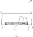
- FIG. 1 is a sectional view along the axial direction of drip irrigation tube 100 according to an embodiment of the present invention.
- drip irrigation tube 100 includes tube 110 and emitter 120.
- Tube 110 is a pipe for carrying irrigation liquid.
- the material of tube 110 is not limited.
- the material of tube 110 is polyethylene.
- a plurality of discharging ports 111 for discharging irrigation liquid are formed at a predetermined interval (for example, 200 to 500 mm) in the axial direction of tube 110.
- the diameter of the opening of discharging port 111 is not limited as long as irrigation liquid can be discharged. In the present embodiment, the diameter of the opening of discharging port 111 is 1.5 mm.
- Emitters 120 are joined on the inner wall surface of tube 110 at respective positions corresponding to discharging ports 111.
- the cross-sectional shape and the cross-sectional area of tube 110 in the direction perpendicular to the axial direction of tube 110 are not limited as long as emitter 120 can be disposed inside tube 110.
- Drip irrigation tube 100 is assembled by joining the rear surface of emitter 120 to the inner wall surface of tube 110.
- the method of joining tube 110 and emitter 120 is not limited. Examples of the method of joining tube 110 and emitter 120 include welding of the resin material of tube 110 or emitter 120, bonding with an adhesive agent and the like.
- discharging port 111 is formed after tube 110 and emitter 120 are joined to each other. Discharging port 111 may be formed before tube 110 and emitter 120 are joined to each other.
- Emitter 120 is joined on the inner wall surface of tube 110 in such a manner as to cover discharging port 112.
- the shape of emitter 120 is not limited as long as emitter 120 can make intimate contact with the inner wall surface of tube 110 and can cover discharging port 111.
- the rear surface, which is joined to the inner wall surface of tube 110, of emitter 120 has a substantially arc shape protruding toward the inner wall surface of tube 110 along the inner wall surface of tube 110.
- emitter 120 has a substantially rectangular shape with chamfered four corners.
- the size of emitter 120 is not limited. In the present embodiment, emitter 120 has a long side length of 25 mm, a short side length of 8 mm, and a height of 2.5 mm.
- FIGS. 2A to 4C illustrate a configuration of emitter 120.
- FIG. 2A is a perspective view of emitter 120 as viewed from the front surface (first surface) side
- FIG. 2B is a perspective view of emitter 120 as viewed from the rear surface (second surface) side.
- FIG. 3A is a plan view of emitter 120
- FIG. 3B is a bottom view of emitter 120
- FIG. 3C is a front view of emitter 120
- FIG. 3D is a right side view of emitter 120.
- FIG. 4A is a sectional view taken along line A-A of FIG. 3A
- FIG. 4B is a sectional view taken along line B-B of FIG. 3A
- FIGS. 5A to 5D illustrate a configuration of emitter main body 121.
- FIG. 5A is a plan view of emitter main body 121
- FIG. 5B is a bottom view of emitter main body 121
- FIG. 5C is a front view of emitter main body 121
- FIG. 5D is a right side view of emitter main body 121.
- FIGS. 6A to 6C illustrate a configuration of film 122.
- FIG. 6A is a plan view of film 122
- FIG. 6B is a front view of film 122
- FIG. 6C is a right side view of film 122.
- FIGS. 7A to 7D illustrate a configuration of cover 123.
- FIG. 7A is a plan view of cover 123
- FIG. 7B is a bottom view of cover 123
- FIG. 7C is a front view of cover 123
- FIG. 7D is a right side view of cover 123.
- emitter 120 is composed of emitter main body 121, film 122, and cover 123. That is, emitter 120 according to the present embodiment has a 3-body structure.
- emitter 120 includes liquid intake part 131, pressure reducing channel 141, flow rate reducing part 161, channel opening-closing part 171, bypass channel 151, and discharging part 181.
- a main portion of emitter 120 is formed in emitter main body 121.
- pressure reducing groove 142 that forms pressure reducing channel 141
- flow rate reducing recess 162 that forms flow rate reducing part 161
- bypass groove 152 that forms bypass channel 151
- channel opening-closing recess 172 that forms channel opening-closing part 171
- discharging part 181 is formed in emitter main body 121.
- Pressure reducing groove 142, flow rate reducing recess 162, bypass groove 152, and channel opening-closing recess 172 open at the first surface.
- discharging part 181 is disposed in the second surface.
- Film 122 deforms in accordance with the pressure of the irrigation liquid in tube 110 to thereby adjust the amount of the irrigation liquid to be sent to discharging part 181.
- Film 122 is disposed on the front surface (first surface) side of emitter main body 121.
- the shape of film 122 in plan view is not limited as long as the above-described function can be ensured. As illustrated in FIGS. 6A to 6C , in the present embodiment, the shape of film 122 in plan view is identical to the external shape of the first surface of emitter main body 121. In addition, as illustrated in FIGS.
- film 122 includes first diaphragm part 166 that forms flow rate reducing part 161 and second diaphragm part 176 that forms channel opening-closing part 171, and, second intake through hole 134 that forms liquid intake part 131 is formed therein.
- Film 122 has a thickness of 0.3 mm, for example.
- Cover 123 positions film 122 with respect to the first surface of emitter main body 121.
- the shape of cover 123 is not limited as long as the above-described function can be ensured.
- cover 123 has a shape of a box with one open side.
- cover 123 is formed such that emitter main body 121 having film 122 disposed on the first surface is fitted to the inside of cover 123.
- liquid intake screen part 132 that forms liquid intake part 131, first screen part 167 that forms flow rate reducing part 161, and second screen part 177 that forms channel opening-closing part 171 are formed in cover 123.
- Emitter 120 is produced by disposing film 122 to the first surface side of emitter main body 121, and then by fitting emitter main body 121 to cover 123 such that film 122 makes contact with the bottom surface of cover 123.
- the material of emitter main body 121 and cover 123 is not limited as long as the material has an elasticity that allows fitting of emitter main body 121 to cover 123.
- Examples of the material of emitter main body 121 and cover 123 include resins such as polyethylene and silicone, and a rubber.
- polyethylene is used as the material of emitter main body 121 and cover 123 in view of manufacturing cost and required elasticity.
- the material of film 122 is not limited as long as the material allows appropriate deformation in accordance with the pressure of the irrigation liquid in tube 110.
- the material of film 122 include a resin such as polyethylene and silicone, and a rubber.
- silicone is used as the material of film 122 in view of required elasticity.
- emitter main body 121, cover 123, and film 122 may be shaped with the same material.
- the flexibility of emitter main body 121, film 122 and cover 123 can be adjusted by use of elastic resin material. Examples of the method of adjusting the flexibility of emitter main body 121, film 122 and cover 123 include selection of an elastic resin, adjustment of the mixing ratio of an elastic resin material to a hard resin material, and the like.
- Each of emitter main body 121, film 122 and cover 123 can be manufactured by injection molding, for example.
- film 122 may be produced by cutting out a commercially available film.
- pressure reducing groove 142 and bypass groove 152 serve as pressure reducing channel 141 and bypass channel 151, respectively.
- flow rate reducing recess 162 and channel opening-closing recess 172 serve as flow rate reducing part 161 and channel opening-closing part 171, respectively.
- cover 123 is attached to emitter main body 121 provided with film 122, liquid intake screen part 132, first intake through hole 133 and second intake through hole 134 serve as liquid intake part 131.
- first channel 153 which including liquid intake part 131, pressure reducing channel 141, flow rate reducing part 161 and discharging part 181, and connects liquid intake part 131 and discharging part 181 together.
- second channel 154 which includes liquid intake part 131, bypass channel 151, channel opening-closing part 171 and discharging part 181, and connects liquid intake part 131 and discharging part 181 together, is formed.
- first channel 153 and second channel 154 distributes irrigation liquid from liquid intake part 131 to discharging part 181.
- Liquid intake part 131 is disposed on the front surface side of emitter 120 (see FIG. 4A ).
- Liquid intake part 131 includes liquid intake screen part 132, first intake through hole 133 (see FIG. 7A ) and second intake through hole 134 (see FIG. 6A ).
- Liquid intake screen part 132 prevents entry, into emitter main body 121, of floating matters in the irrigation liquid to be taken into emitter 120.
- Liquid intake screen part 132 is formed in the entirety of the front surface of cover 123. Liquid intake screen part 132 opens to the interior of tube 110, and includes cover recess 135 and a plurality of projected lines 136.
- Cover recess 135 is a single recess formed in the entirety of the top surface of cover 123.
- the depth of cover recess 135 is not limited, and is appropriately set in accordance with the size of emitter 120.
- Projected lines 136 are disposed on the bottom surface of cover recess 135.
- first intake through hole 133, flow rate reducing through hole 168 and channel opening-closing through hole 178 open at the bottom surface of cover recess 135 (see FIG. 7A and FIG. 7B ).
- Projected lines 136 are disposed on the bottom surface of cover recess 135.
- the installation and number of projected lines 136 are not limited as long as entry of floating matters of irrigation liquid can be prevented while allowing entry of the irrigation liquid from the opening side of cover recess 135.
- projected line 136 is disposed along the longitudinal axial direction of emitter 120. Projected line 136 may be formed such that the width of projected line 136 decreases from the bottom surface of cover recess 135 toward the front surface of cover 123, or that the width of projected line 136 is the same from the bottom surface of cover recess 135 to the front surface of cover 123.
- First intake through hole 133 opens at the bottom surface of cover recess 135.
- the shape and number of first intake through hole 133 are not limited as long as the irrigation liquid taken into cover recess 135 can be guided into emitter main body 121 through second intake through hole 134.
- first intake through hole 133 is five rectangular holes formed along the longitudinal axial direction of the bottom surface of cover recess 135 (see FIG. 7B ).
- Second intake through hole 134 is formed in film 122.
- the shape and number of second intake through hole 134 are not limited as long as the irrigation liquid taken from first intake through hole 133 can be guided to pressure reducing channel 141 and bypass channel 151.
- second intake through hole 134 has a shape of two circles (see FIG. 6A ).
- Liquid intake screen part 132 prevents the floating matters of the irrigation liquid which has passed through tube 110 from entering cover recess 135, and this irrigation liquid is then taken into emitter main body 121 through first intake through hole 133 and second intake through hole 134.
- Pressure reducing channel 141 (pressure reducing groove 142), which is disposed in first channel 153 located upstream of flow rate reducing part 161, connects liquid intake part 131 and flow rate reducing part 161 together.
- Pressure reducing channel 141 (pressure reducing groove 142) guides the irrigation liquid taken from liquid intake part 131 to flow rate reducing part 161 while reducing the pressure of the irrigation liquid.
- Pressure reducing channel 141 is disposed at a center portion of emitter 120.
- Pressure reducing channel 141 is composed of pressure reducing groove 142, and film 122 for closing the opening of pressure reducing groove 142.
- Pressure reducing groove 142 is formed in the front surface (first surface) of emitter main body 121.
- pressure reducing groove 142 is not limited as long as the above-described function can be ensured as pressure reducing channel 141.
- pressure reducing groove 142 has a zigzag shape in plan view.
- protrusions 143 each of which has a substantially triangular prism shape and protrudes from the inner surface of pressure reducing groove 142, are alternately disposed along the flow direction of the irrigation liquid.
- protrusions 143 are disposed such that the tip of each protrusion 143 does not cross the central axis of end pressure reducing groove 142.
- pressure reducing groove 142 and a part of the rear surface of film 122 form pressure reducing channel 141. At least a part of the irrigation liquid taken from liquid intake part 131 is guided to flow rate reducing part 161 while the pressure thereof is reduced by reducing channel 141. As elaborated later, pressure reducing channel 141 operates mainly when the pressure of irrigation liquid is high.
- Bypass channel 151 (bypass groove 152), which is disposed in second channel 154 located upstream of channel opening-closing part 171, connects liquid intake part 131 and channel opening-closing part 171 together.
- Bypass channel 151 (bypass groove 152) guides, to channel opening-closing part 171, the irrigation liquid taken from liquid intake part 131 while maintaining the pressure of the liquid at a value higher than that of the irrigation liquid which has flown through pressure reducing channel 141 (pressure reducing groove 142).
- bypass groove 152 and a part of the rear surface of film 122 form bypass channel 151.
- a part of the irrigation liquid taken from liquid intake part 131 passes through bypass channel 151 and is guided to channel opening-closing part 171.
- bypass channel 151 operates only when the pressure of the irrigation liquid is low.
- a channel screen part may be disposed in bypass groove 152.
- the channel screen part captures floating matters in the irrigation liquid which have not collected by liquid intake screen part 132.
- the configuration of the channel screen part is not limited as long as the above-described function can be ensured.
- the channel screen part is a plurality of columnar protrusions disposed on the bottom surface of bypass groove 152.
- Flow rate reducing part 161 is disposed between pressure reducing channel 141 and discharging part 181 in first channel 153. Flow rate reducing part 161 sends the irrigation liquid to irrigation liquid discharging part 181 while reducing the flow rate of the irrigation liquid in accordance with the pressure of the irrigation liquid in tube 110.
- the configuration of flow rate reducing part 161 is not limited as long as the above-described function can be ensured.
- flow rate reducing part 161 includes flow rate reducing recess 162, first valve seat part 163, communication groove 164, first discharging through hole 165 communicated with discharging part 181, first diaphragm part 166, which is a part of film 122, and first screen part 167.
- the shape of flow rate reducing recess 162 in plan view is not limited.
- the shape of flow rate reducing recess 162 in plan view may be a substantially rectangular shape with chamfered four corners, or a substantially semicircular shape.
- the shape of flow rate reducing recess 162 in plan view is a substantially rectangular shape with chamfered four corners.
- First discharging through hole 165 communicated with discharging part 181 opens at the bottom surface of flow rate reducing recess 162, and first valve seat part 163 is disposed in the bottom surface of flow rate reducing recess 162.
- pressure reducing channel 141 pressure reducing groove 142
- the depth of flow rate reducing recess 162 is not limited as long as the depth is equal to or greater than the depth of communication groove 164 and pressure reducing groove 142.
- First discharging through hole 165 opens at a center portion of the bottom surface of flow rate reducing recess 162, and is communicated with discharging part 181.
- First valve seat part 163 is disposed in the bottom surface of flow rate reducing recess 162 in such a manner as to surround first discharging through hole 165.
- First valve seat part 163 is formed such that first diaphragm part 166 can make intimate contact with first valve seat part 163 when the pressure of the irrigation liquid flowing through tube 110 is the second pressure or greater. When first diaphragm part 166 makes contact with first valve seat part 163, the flow rate of the irrigation liquid flowing into discharging part 181 from flow rate reducing recess 162 is reduced.
- first valve seat part 163 is not limited as long as the above-described function can be ensured.
- first valve seat part 163 has a shape of an annular protrusion.
- Communication groove 164 which communicates between the inside of flow rate reducing recess 162 and first discharging through hole 165, is formed in a part of the region of first valve seat part 163 where first diaphragm part 166 can make intimate contact with first valve seat part 163.
- First diaphragm part 166 is a part of film 122.
- First diaphragm part 166 is disposed as a partition between the inside of flow rate reducing recess 162 and the inside of tube 110.
- First diaphragm part 166 deforms in such a manner as to make contact with first valve seat part 163 in accordance with the pressure of the irrigation liquid in tube 110.
- first diaphragm part 166 deforms toward first valve seat part 163 as the pressure of the irrigation liquid increases, and finally makes contact with first valve seat part 163.
- First screen part 167 sends the irrigation liquid to the front surface of first diaphragm part 166 with almost no change in pressure of the irrigation liquid.
- First screen part 167 includes a part of cover recess 135, some of projected lines 136, and flow rate reducing through hole 168.
- Flow rate reducing through hole 168 is formed in a bottom portion of cover 123 at a position corresponding to first diaphragm part 166.
- the shape and number of flow rate reducing through hole 168 are not limited as long as the above-described function can be ensured.
- the shape of flow rate reducing through hole 168 in plan view may be a circular shape or a rectangular shape. In the present embodiment, flow rate reducing through hole 168 has a rectangular shape in plan view.
- flow rate reducing through hole 168 is not limited.
- flow rate reducing through holes 168 is five long holes formed along the minor axis direction of the bottom surface of cover recess 135. The long holes are covered with projected lines 136, and therefore each flow rate reducing through hole 168 appears to be divided into multiple through holes as viewed from the front side.
- Channel opening-closing part 171 is disposed between bypass channel 151 and discharging part 181 in second channel 154. In accordance with the pressure in tube 110, channel opening-closing part 171 opens second channel 154 and sends the irrigation liquid to discharging part 181.
- the configuration of channel opening-closing part 171 is not limited as long as the above-described function can be ensured.
- channel opening-closing part 171 includes channel opening-closing recess 172, second valve seat part 173, second discharging through hole 175 communicated with discharging part 181, second diaphragm part 176, which is a part of film 122, and second screen part 177.
- channel opening-closing recess 172 in plan view is not limited.
- the shape of channel opening-closing recess 172 in plan view may be a substantially rectangular shape with chamfered four corners, or a substantially semicircular shape.
- channel opening-closing recess 172 has a substantially rectangular shape with chamfered four corners in plan view.
- Second discharging through hole 175 communicated with discharging part 181, and second valve seat part 173 are disposed in the bottom surface of channel opening-closing recess 172.
- bypass channel 151 (bypass groove 152) is connected with the side surface of channel opening-closing recess 172.
- Second valve seat part 173 is disposed on the first surface side relative to first valve seat part 163.
- Second discharging through hole 175 opens at a center portion of the bottom surface of channel opening-closing recess 172, and is communicated with discharging part 181.
- Second valve seat part 173 is disposed in the bottom surface of channel opening-closing recess 172 in such a manner as to surround second discharging through hole 175.
- second valve seat part 173 is disposed to face second diaphragm part 176 without making contact with second diaphragm part 176, and is formed such that second diaphragm part 176 can make intimate contact with second valve seat part 173 when the pressure of the irrigation liquid flowing through tube 110 is the first pressure or greater.
- second diaphragm part 176 makes intimate contact with second valve seat part 173 to close second discharging through hole 175, and thus closes second channel 154.
- the shape of second valve seat part 173 is not limited as long as the above-described function can be ensured.
- second valve seat part 173 is an annular protrusion.
- Second diaphragm part 176 is a part of film 122. Second diaphragm part 176 is disposed as a partition between the inside of channel opening-closing recess 172 and the inside of tube 110. In accordance with the pressure of the irrigation liquid in tube 110, second diaphragm part 176 deforms to make contact with second valve seat part 173. To be more specific, as the pressure of the irrigation liquid increases, second diaphragm part 176 deforms toward second valve seat part 173, and when the pressure of irrigation liquid becomes the first pressure, second diaphragm part 176 makes contact with second valve seat part 173. In this manner, second channel 154 (second discharging through hole 175) is closed.
- Second screen part 177 sends the irrigation liquid to the front surface of second diaphragm part 176 with almost no change in pressure of the irrigation liquid.
- Second screen part 177 includes a part of cover recess 135, some of projected lines 136, and channel opening-closing through hole 178.
- Channel opening-closing through hole 178 is formed in a bottom portion of cover 123 at a position corresponding to second diaphragm part 176.
- the shape and number of channel opening-closing through hole 178 are not limited as long as the above-described function can be ensured.
- Channel opening-closing through hole 178 may have a circular shape or a rectangular shape in plan view. In the present embodiment, channel opening-closing through hole 178 has a rectangular shape in plan view.
- channel opening-closing through hole 178 is not limited.
- channel opening-closing through hole 178 is five long holes formed along the minor axis direction of the bottom surface of cover recess 135. The long holes are covered with projected lines 136, and therefore each channel opening-closing through hole 178 appears to be divided into multiple through holes as viewed from the front side.
- Discharging part 181 is disposed on the rear surface side of emitter 120 facing discharging port 111. Discharging part 181 sends the irrigation liquid from first discharging through hole 165 and second discharging through hole 175 to discharging port 111 of tube 110.
- the configuration of discharging part 181 is not limited as long as the above-described function can be ensured.
- discharging part 181 includes discharging recess 182, a pair of discharging grooves 183, and a pair of entry preventing parts 184.
- Discharging recess 182 opens at the rear surface of emitter main body 121.
- Discharging recess 182 has a substantially rectangular shape in plan view.
- the pair of discharging grooves 183 open toward each other at opposite side surfaces of discharging recess 182.
- the pair of entry preventing parts 184 prevents entry of foreign matters from discharging port 111.
- the position of entry preventing part 184 is not limited as long as the above-described function can be ensured.
- entry preventing part 184 is disposed such that entry preventing part 184 is located between first discharging through hole 165 and discharging port 111, and between second discharging through hole 175 and discharging port when emitter 120 is joined to tube 110.
- irrigation liquid is fed into tube 110.
- the irrigation liquid include water, liquid fertilizer, agricultural chemicals and mixtures thereof.
- the pressure of the irrigation liquid that is fed to drip irrigation tube 100 is 0.1 MPa or lower in view of simply implementing the drip irrigation method, or preventing damaging of tube 110 and emitter 120.
- the irrigation liquid in tube 110 is taken into emitter main body 121 from liquid intake part 131.
- the irrigation liquid in tube 110 enters cover recess 135 from the gap between each projected line 136, and passes through first intake through hole 133 and second intake through hole 134.
- liquid intake part 131 can remove floating matters in the irrigation liquid since liquid intake part 131 includes liquid intake screen part 132 (the gap between each projected line 136).
- the irrigation liquid taken from liquid intake part 131 reaches the upstream end of bypass channel 151.
- the irrigation liquid reaching bypass channel 151 flows toward the downstream of bypass channel 151, and flows into pressure reducing channel 141.
- the irrigation liquid first advances through bypass channel 151 that causes smaller pressure drop and has a shorter channel length in comparison with pressure reducing channel 141.
- the irrigation liquid having entered bypass channel 151 flows into channel opening-closing part 171.
- the irrigation liquid having entered channel opening-closing part 171 flows into discharging part 181 when channel opening-closing part 171 is open.
- the irrigation liquid having entered discharging part 181 is discharged out of tube 110 from discharging port 111 of tube 110.
- the irrigation liquid having entered pressure reducing channel 141 reaches flow rate reducing part 161.
- the irrigation liquid having entered flow rate reducing part 161 flows into discharging part 181.
- the irrigation liquid having entered discharging part 181 is discharged out of tube 110 from discharging port 111 of tube 110.
- the flow rate of the irrigation liquid is controlled by first diaphragm part 166 in accordance with the pressure of the irrigation liquid in tube 110, whereas in channel opening-closing part 171, the flow rate of the irrigation liquid is controlled by second diaphragm part 176 in accordance with the pressure of the irrigation liquid in tube 110.
- first diaphragm part 166 in accordance with the pressure of the irrigation liquid in tube 110
- second diaphragm part 176 in accordance with the pressure of the irrigation liquid in tube 110.
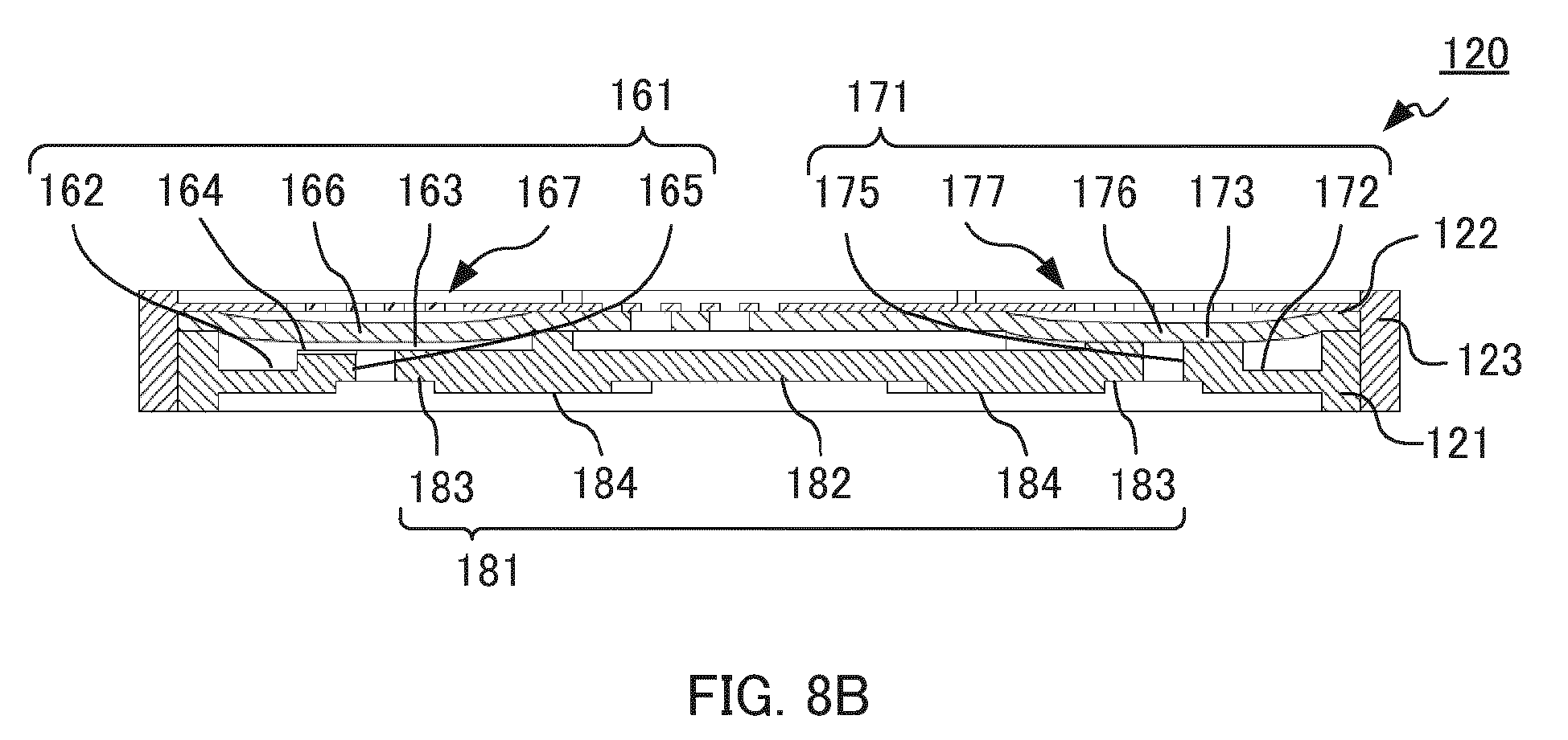
- FIGS. 8A to 8C are sectional views of emitter 120 illustrating a relationship between operations of flow rate reducing part 161 and channel opening-closing part 171.
- FIG. 8A is a sectional view of a state where no irrigation liquid is fed to tube 110
- FIG. 8B is a sectional view of a state where the pressure of the irrigation liquid in tube 110 is a first pressure
- FIG. 8C is a sectional view of a state where the pressure of the irrigation liquid in tube 110 is a second pressure greater than the first pressure.
- FIG. 9 is a graph showing an exemplary relationship between the pressure of the irrigation liquid in tube 110 and the flow rate of the irrigation liquid dropped from discharging port 111.
- FIG. 8A is a sectional view of a state where no irrigation liquid is fed to tube 110
- FIG. 8B is a sectional view of a state where the pressure of the irrigation liquid in tube 110 is a first pressure
- FIG. 8C is a sectional view of a state where the pressure of the irrigation liquid
- the solid line indicates a total flow rate of the irrigation liquid dropped from discharging port 111
- the broken line indicates a flow rate of the irrigation liquid having flown through (bypass channel 151) second channel 154
- the dashed line indicates a flow rate of the irrigation liquid having flown through (pressure reducing channel 141) first channel 153.
- the abscissa indicates a pressure (MPa) of irrigation liquid
- the ordinate indicates a flow rate (L/h) of the irrigation liquid discharged from discharging port 111.
- first diaphragm part 166 and second diaphragm part 176 are not deformed (see FIG. 8A ).
- first diaphragm part 166 of flow rate reducing part 161 starts to deform toward first valve seat part 163.
- second diaphragm part 176 of channel opening-closing part 171 starts to deform toward second valve seat part 173.
- first diaphragm part 166 is not in contact with first valve seat part 163, and second diaphragm part 176 is not in contact with second valve seat part 173, and therefore, the irrigation liquid taken from liquid intake part 131 is discharged to the outside from discharging port 111 of tube 110 through first channel 153 (pressure reducing channel 141, flow rate reducing part 161 and discharging part 181) and second channel 154 (bypass channel 151, channel opening-closing part 171, flow rate reducing part 161 and discharging part 181).
- first channel 153 pressure reducing channel 141, flow rate reducing part 161 and discharging part 181
- second channel 154 bypass channel 151, channel opening-closing part 171, flow rate reducing part 161 and discharging part 181).
- second diaphragm part 176 makes contact with second valve seat part 173 and closes second channel 154 (see FIG. 8B ). At this time, first diaphragm part 166 is not in contact with first valve seat part 163. In this manner, when the pressure of the irrigation liquid in tube 110 is so increased as to deform film 122, second diaphragm part 176 comes closer to second valve seat part 173, and accordingly the amount of the irrigation liquid that is discharged through second channel 154 decreases. Then, when the pressure of the irrigation liquid in tube 110 reaches the first pressure, the irrigation liquid in second channel 154 is not discharged from discharging port 111. As a result, the irrigation liquid taken from intake part 131 is discharged to the outside from discharging port 111 of tube 110 through first channel 153.
- first diaphragm part 166 When the pressure of the irrigation liquid in tube 110 further increases, first diaphragm part 166 further deforms toward first valve seat part 163. In a normal configuration, the amount of the irrigation liquid that flows through first channel 153 increases as the pressure of the irrigation liquid increases; however, in emitter 120 according to the present embodiment, excessive increase in the amount of the irrigation liquid that flows through first channel 153 is prevented by reducing the pressure of the irrigation liquid with pressure reducing channel 141 and by reducing the distance between first diaphragm part 166 and first valve seat part 163. When the pressure of the irrigation liquid in tube 110 is equal to or greater than the second pressure, which is greater than the first pressure, first diaphragm part 166 makes contact with first valve seat part 163 (see FIG. 8C ).
- flow rate reducing part 161 and channel opening-closing part 171 operate such that the amounts of the liquid flowing therethrough are offset each other in accordance with the pressure of the irrigation liquid in tube 110, and thus drip irrigation tube 100 according to the present embodiment can discharge a constant amount of irrigation liquid out of tube 110 regardless whether the pressure of the irrigation liquid is high or low (see the solid line indicated in FIG. 9 ).
- drip irrigation tube 100 includes channel opening-closing part 171 that operates mainly in the low pressure state, and flow rate reducing part 161 that operates mainly in the high pressure state.
- drip irrigation tube 100 according to the present embodiment can quantitatively drop the irrigation liquid regardless of the pressure of the irrigation liquid in tube 110.
- pressure reducing groove 142 and bypass groove 152 open at the first surface, and serve as first channel 153 and second channel 154, respectively when the openings thereof are closed with film 122 in the present embodiment
- pressure reducing groove 142 and bypass groove 152 may open at the second surface.
- the openings of pressure reducing groove 142 and the opening of bypass groove 152 are closed by the inner wall surface of tube 110.
- first channel 153 and second channel 154 may be formed inside emitter main body 121.
- the contact timing of deformed film 122 is adjusted by changing the positions (heights) of first valve seat part 163 and second valve seat part 173
- the positions (heights) of first valve seat part 163 and second valve seat part 173 may be set at the same depth.
- the contact timing of deformed film 122 may be adjusted by changing the thicknesses and/or the materials (elasticities) of first diaphragm part 166 and second diaphragm part 176.
- flow rate reducing part 161 and channel opening-closing part 171 are independent of each other in the present embodiment, flow rate reducing part 161 and channel opening-closing part 171 may be communicated with each other.
- an emitter which can drop liquid with an appropriate rate by the pressure of the liquid to be dropped can be easily provided. Accordingly, popularization of the emitter in the technical fields of drip irrigations and endurance tests where long-term dropping is required, and development in the technical fields can be expected.
Landscapes
- Life Sciences & Earth Sciences (AREA)
- Engineering & Computer Science (AREA)
- Water Supply & Treatment (AREA)
- Environmental Sciences (AREA)
- Soil Sciences (AREA)
- Infusion, Injection, And Reservoir Apparatuses (AREA)
- Nozzles (AREA)
Abstract

Description
- The present invention relates to an emitter, and a drip irrigation tube including the emitter.
- Conventionally, a drip irrigation method is known as a method for culturing plants. In the drip irrigation method, a drip irrigation tube is disposed on the soil where plants are planted, and irrigation liquid such as water and liquid fertilizer is dropped to the soil from the drip irrigation tube. The drip irrigation method has been increasingly attracting attention in recent years since the method can minimize the consumption rate of the irrigation liquid.
- Normally, the drip irrigation tube includes a tube provided with a plurality of through holes for discharging irrigation liquid, and a plurality of emitters (also called "drippers") for discharging irrigation liquid from respective through holes. In addition, emitters which are joined on the inner wall surface of a tube (see, for example, PTL 1), and emitters which are inserted to a tube from the outside of the tube are known.
- PTL 1 discloses an emitter configured to be joined on the inner wall surface of a tube. The emitter disclosed in PTL 1 includes a first member including a water intake port for receiving irrigation liquid, a second member including an outlet for discharging the irrigation liquid, and a film member disposed between the first member and the second member. On the inside of the first member, a valve seat part disposed is formed in such a manner as to surround the water intake port, and a pressure reducing groove that serves as a part of a pressure reducing channel is opened. In the film member, a through hole is formed at a position corresponding to the downstream end of the pressure reducing groove.
- When the first member, the film member and the second member are stacked, the pressure reducing channel is formed, and the film member makes contact with the valve seat part to close the water intake port. In addition, a channel for carrying the irrigation liquid from the water intake port to the outlet is formed.
- In the emitter disclosed in PTL 1, when the pressure of the irrigation liquid in the tube is equal to or greater than a predetermined pressure, the film member closing the water intake port is pushed by the irrigation liquid, and the irrigation liquid flows into the emitter. The pressure of the irrigation liquid having entered the emitter is reduced by the reducing channel, and thus the irrigation liquid is quantitatively discharged from the outlet.
- PTL 1 Japanese Patent Application Laid-Open No.
2010-046094 - In the drip irrigation tube using the emitter disclosed in PTL 1, however, the irrigation liquid flows into the emitter only when the pressure of the irrigation liquid in the tube is equal to or greater than the predetermined pressure, and as such the tube disclosed in PTL 1 does not function when the pressure of the irrigation liquid in the tube is significantly low. Consequently, emitters disposed at a position remote from the liquid feed pump for sending the irrigation liquid to the tube do not appropriately function while emitters near the liquid feed pump appropriately function. Consequently, the flow rate of the irrigation liquid to be supplied varies depending on the watering position, and the watering distance is limited.
- In view of this, an object of the present invention is to provide an emitter and a drip irrigation tube capable of quantitatively discharging irrigation liquid not only when the pressure of the irrigation liquid is high, but also when the pressure is low.
- To solve the above-mentioned problems, an emitter according to an embodiment of the present invention includes an emitter main body, a film having flexibility disposed on a first surface of the emitter main body, and a cover for positioning the film with respect to the emitter main body, the emitter being configured to be joined on an inner wall surface of a tube configured to distribute irrigation liquid at a position corresponding to a discharging port communicating between inside and outside of the tube, the emitter being configured to quantitatively discharge the irrigation liquid in the tube to the outside of the tube from the discharging port, the emitter including: a liquid intake part for receiving the irrigation liquid; a discharging part disposed in a second surface of the emitter main body and configured to discharge the irrigation liquid, the second surface being opposite to the first surface and being configured to face the discharging port; a first channel configured to connect the liquid intake part and the discharging part together, and to distribute the irrigation liquid; a second channel configured to connect the liquid intake part and the discharging part together, and to distribute the irrigation liquid; a flow rate reducing part disposed in the first channel and including a flow rate reducing recess opening at the first surface and the film closing an opening of the flow rate reducing recess, the flow rate reducing part being configured to reduce a flow rate of the irrigation liquid flowing to the discharging port by deformation of the film in accordance with a pressure of the irrigation liquid in the tube; a channel opening-closing part disposed in the second channel and including a channel opening-closing recess opening at the first surface and the film closing an opening of the channel opening-closing recess, the channel opening-closing part being configured to open and close the second channel by deformation of the film in accordance with a pressure of the irrigation liquid in the tube; a pressure reducing channel disposed in the first channel located upstream of the flow rate reducing part, the pressure reducing channel being configured to guide, to the flow rate reducing part, the irrigation liquid received from the liquid intake part while reducing a pressure of the irrigation liquid received from the liquid intake part; and a bypass channel disposed in the second channel located upstream of the channel opening-closing part, the bypass channel being configured to guide, to the channel opening-closing part, the irrigation liquid received from the liquid intake part while maintaining a pressure of the irrigation liquid received from the liquid intake part at a pressure higher than a pressure of the irrigation liquid which has flown through the pressure reducing channel. When the pressure of the irrigation liquid flowing through the tube is lower than a first pressure, the irrigation liquid received from the liquid intake part is guided to the discharging part through the pressure reducing channel and the bypass channel. When the pressure of the irrigation liquid flowing through the tube is equal to or higher than the first pressure, the second channel is closed by the channel opening-closing part, and the irrigation liquid received from the liquid intake part is guided to the discharging part through the pressure reducing channel.
- In addition, to solve the above-mentioned problems, a drip irrigation tube according to an embodiment of the present invention includes: a tube including a discharging port for discharging irrigation liquid; and the above-mentioned emitter, the emitter being joined on the inner wall surface of the tube at a position corresponding to the discharging port.
- With the emitter and the drip irrigation tube according to the embodiment of the present invention, it is possible to quantitatively discharge irrigation liquid not only when the pressure of the irrigation liquid is high, but also when the pressure is low. In addition, the emitter and the drip irrigation tube according to the embodiment of the present invention can achieve quantitative watering over long distance.
-
-
FIG. 1 is a sectional view of a drip irrigation tube; -
FIGS. 2A and 2B are perspective views of an emitter; -
FIGS. 3A to 3D illustrate a configuration of the emitter; -
FIGS. 4A to 4C are sectional views of the emitter; -
FIGS. 5A to 5D illustrate a configuration of an emitter main body; -
FIGS. 6A to 6C illustrate a configuration of a film; -
FIGS. 7A to 7D illustrate a configuration of a cover; -
FIGS. 8A to 8C are sectional views for describing operations of the emitter; and -
FIG. 9 is a graph showing an exemplary relationship between a pressure of irrigation liquid in the drip irrigation tube and a flow rate of irrigation liquid dropped from a discharging port. - An embodiment of the present invention is elaborated below with reference to the accompanying drawings.
-
FIG. 1 is a sectional view along the axial direction ofdrip irrigation tube 100 according to an embodiment of the present invention. - As illustrated in
FIG. 1 ,drip irrigation tube 100 includestube 110 andemitter 120. - Tube 110 is a pipe for carrying irrigation liquid. The material of
tube 110 is not limited. In the present embodiment, the material oftube 110 is polyethylene. In the wall oftube 110, a plurality ofdischarging ports 111 for discharging irrigation liquid are formed at a predetermined interval (for example, 200 to 500 mm) in the axial direction oftube 110. The diameter of the opening ofdischarging port 111 is not limited as long as irrigation liquid can be discharged. In the present embodiment, the diameter of the opening ofdischarging port 111 is 1.5 mm.Emitters 120 are joined on the inner wall surface oftube 110 at respective positions corresponding todischarging ports 111. The cross-sectional shape and the cross-sectional area oftube 110 in the direction perpendicular to the axial direction oftube 110 are not limited as long asemitter 120 can be disposed insidetube 110. -
Drip irrigation tube 100 is assembled by joining the rear surface ofemitter 120 to the inner wall surface oftube 110. The method of joiningtube 110 andemitter 120 is not limited. Examples of the method of joiningtube 110 andemitter 120 include welding of the resin material oftube 110 oremitter 120, bonding with an adhesive agent and the like. Normally,discharging port 111 is formed aftertube 110 andemitter 120 are joined to each other. Dischargingport 111 may be formed beforetube 110 andemitter 120 are joined to each other. -
Emitter 120 is joined on the inner wall surface oftube 110 in such a manner as to cover discharging port 112. The shape ofemitter 120 is not limited as long asemitter 120 can make intimate contact with the inner wall surface oftube 110 and can cover dischargingport 111. In the present embodiment, in the cross-section ofemitter 120 in the direction perpendicular to the axial direction oftube 110, the rear surface, which is joined to the inner wall surface oftube 110, ofemitter 120 has a substantially arc shape protruding toward the inner wall surface oftube 110 along the inner wall surface oftube 110. In addition, in plan view,emitter 120 has a substantially rectangular shape with chamfered four corners. The size ofemitter 120 is not limited. In the present embodiment,emitter 120 has a long side length of 25 mm, a short side length of 8 mm, and a height of 2.5 mm. -
FIGS. 2A to 4C illustrate a configuration ofemitter 120.FIG. 2A is a perspective view ofemitter 120 as viewed from the front surface (first surface) side, andFIG. 2B is a perspective view ofemitter 120 as viewed from the rear surface (second surface) side.FIG. 3A is a plan view ofemitter 120,FIG. 3B is a bottom view ofemitter 120,FIG. 3C is a front view ofemitter 120, andFIG. 3D is a right side view ofemitter 120.FIG. 4A is a sectional view taken along line A-A ofFIG. 3A ,FIG. 4B is a sectional view taken along line B-B ofFIG. 3A , andFIG. 4C is a sectional view taken along line C-C ofFIG. 3A .FIGS. 5A to 5D illustrate a configuration of emittermain body 121.FIG. 5A is a plan view of emittermain body 121,FIG. 5B is a bottom view of emittermain body 121,FIG. 5C is a front view of emittermain body 121, andFIG. 5D is a right side view of emittermain body 121.FIGS. 6A to 6C illustrate a configuration offilm 122.FIG. 6A is a plan view offilm 122,FIG. 6B is a front view offilm 122, andFIG. 6C is a right side view offilm 122.FIGS. 7A to 7D illustrate a configuration ofcover 123.FIG. 7A is a plan view ofcover 123,FIG. 7B is a bottom view ofcover 123,FIG. 7C is a front view ofcover 123, andFIG. 7D is a right side view ofcover 123. - As illustrated in
FIGS. 2A to 4C ,emitter 120 is composed of emittermain body 121,film 122, and cover 123. That is,emitter 120 according to the present embodiment has a 3-body structure. In addition,emitter 120 includesliquid intake part 131,pressure reducing channel 141, flowrate reducing part 161, channel opening-closingpart 171,bypass channel 151, and dischargingpart 181. - A main portion of
emitter 120 is formed in emittermain body 121. As illustrated inFIGS. 4A to 5D , in the present embodiment,pressure reducing groove 142 that formspressure reducing channel 141, flowrate reducing recess 162 that forms flowrate reducing part 161,bypass groove 152 that formsbypass channel 151, channel opening-closing recess 172 that forms channel opening-closingpart 171, and dischargingpart 181 are formed in emittermain body 121.Pressure reducing groove 142, flowrate reducing recess 162,bypass groove 152, and channel opening-closing recess 172 open at the first surface. In addition, dischargingpart 181 is disposed in the second surface. -
Film 122 deforms in accordance with the pressure of the irrigation liquid intube 110 to thereby adjust the amount of the irrigation liquid to be sent to dischargingpart 181.Film 122 is disposed on the front surface (first surface) side of emittermain body 121. The shape offilm 122 in plan view is not limited as long as the above-described function can be ensured. As illustrated inFIGS. 6A to 6C , in the present embodiment, the shape offilm 122 in plan view is identical to the external shape of the first surface of emittermain body 121. In addition, as illustrated inFIGS. 4A to 6C , in the present embodiment,film 122 includesfirst diaphragm part 166 that forms flowrate reducing part 161 andsecond diaphragm part 176 that forms channel opening-closingpart 171, and, second intake throughhole 134 that formsliquid intake part 131 is formed therein.Film 122 has a thickness of 0.3 mm, for example. - Cover 123
positions film 122 with respect to the first surface of emittermain body 121. The shape ofcover 123 is not limited as long as the above-described function can be ensured. As illustrated inFIGS. 7A to 7D , in the present embodiment,cover 123 has a shape of a box with one open side. In addition,cover 123 is formed such that emittermain body 121 havingfilm 122 disposed on the first surface is fitted to the inside ofcover 123. In addition, in the present embodiment, liquidintake screen part 132 that formsliquid intake part 131,first screen part 167 that forms flowrate reducing part 161, andsecond screen part 177 that forms channel opening-closingpart 171 are formed incover 123. -
Emitter 120 is produced by disposingfilm 122 to the first surface side of emittermain body 121, and then by fitting emittermain body 121 to cover 123 such thatfilm 122 makes contact with the bottom surface ofcover 123. - The material of emitter
main body 121 and cover 123 is not limited as long as the material has an elasticity that allows fitting of emittermain body 121 to cover 123. Examples of the material of emittermain body 121 and cover 123 include resins such as polyethylene and silicone, and a rubber. In the present embodiment, polyethylene is used as the material of emittermain body 121 and cover 123 in view of manufacturing cost and required elasticity. In addition, the material offilm 122 is not limited as long as the material allows appropriate deformation in accordance with the pressure of the irrigation liquid intube 110. Examples of the material offilm 122 include a resin such as polyethylene and silicone, and a rubber. In the present embodiment, silicone is used as the material offilm 122 in view of required elasticity. Whilefilm 122 is shaped with a material different from that of emittermain body 121 and cover 123 in the present embodiment, emittermain body 121,cover 123, andfilm 122 may be shaped with the same material. The flexibility of emittermain body 121,film 122 and cover 123 can be adjusted by use of elastic resin material. Examples of the method of adjusting the flexibility of emittermain body 121,film 122 and cover 123 include selection of an elastic resin, adjustment of the mixing ratio of an elastic resin material to a hard resin material, and the like. Each of emittermain body 121,film 122 and cover 123 can be manufactured by injection molding, for example. In addition,film 122 may be produced by cutting out a commercially available film. - When
film 122 is disposed on the first surface of emittermain body 121,pressure reducing groove 142 andbypass groove 152 serve aspressure reducing channel 141 andbypass channel 151, respectively. Meanwhile, flowrate reducing recess 162 and channel opening-closing recess 172 serve as flowrate reducing part 161 and channel opening-closingpart 171, respectively. In addition, whencover 123 is attached to emittermain body 121 provided withfilm 122, liquidintake screen part 132, first intake throughhole 133 and second intake throughhole 134 serve asliquid intake part 131. In this manner,first channel 153, which includingliquid intake part 131,pressure reducing channel 141, flowrate reducing part 161 and dischargingpart 181, and connectsliquid intake part 131 and dischargingpart 181 together, is formed. In addition,second channel 154, which includesliquid intake part 131,bypass channel 151, channel opening-closingpart 171 and dischargingpart 181, and connectsliquid intake part 131 and dischargingpart 181 together, is formed. Each offirst channel 153 andsecond channel 154 distributes irrigation liquid fromliquid intake part 131 to dischargingpart 181. -
Liquid intake part 131 is disposed on the front surface side of emitter 120 (seeFIG. 4A ).Liquid intake part 131 includes liquidintake screen part 132, first intake through hole 133 (seeFIG. 7A ) and second intake through hole 134 (seeFIG. 6A ). - Liquid
intake screen part 132 prevents entry, into emittermain body 121, of floating matters in the irrigation liquid to be taken intoemitter 120. Liquidintake screen part 132 is formed in the entirety of the front surface ofcover 123. Liquidintake screen part 132 opens to the interior oftube 110, and includescover recess 135 and a plurality of projectedlines 136. -
Cover recess 135 is a single recess formed in the entirety of the top surface ofcover 123. The depth ofcover recess 135 is not limited, and is appropriately set in accordance with the size ofemitter 120. Projectedlines 136 are disposed on the bottom surface ofcover recess 135. In addition, first intake throughhole 133, flow rate reducing throughhole 168 and channel opening-closing throughhole 178 open at the bottom surface of cover recess 135 (seeFIG. 7A and FIG. 7B ). - Projected
lines 136 are disposed on the bottom surface ofcover recess 135. The installation and number of projectedlines 136 are not limited as long as entry of floating matters of irrigation liquid can be prevented while allowing entry of the irrigation liquid from the opening side ofcover recess 135. In the present embodiment, projectedline 136 is disposed along the longitudinal axial direction ofemitter 120. Projectedline 136 may be formed such that the width of projectedline 136 decreases from the bottom surface ofcover recess 135 toward the front surface ofcover 123, or that the width of projectedline 136 is the same from the bottom surface ofcover recess 135 to the front surface ofcover 123. - First intake through
hole 133 opens at the bottom surface ofcover recess 135. The shape and number of first intake throughhole 133 are not limited as long as the irrigation liquid taken intocover recess 135 can be guided into emittermain body 121 through second intake throughhole 134. In the present embodiment, first intake throughhole 133 is five rectangular holes formed along the longitudinal axial direction of the bottom surface of cover recess 135 (seeFIG. 7B ). - Second intake through
hole 134 is formed infilm 122. The shape and number of second intake throughhole 134 are not limited as long as the irrigation liquid taken from first intake throughhole 133 can be guided topressure reducing channel 141 andbypass channel 151. In the present embodiment, second intake throughhole 134 has a shape of two circles (seeFIG. 6A ). - Liquid
intake screen part 132 prevents the floating matters of the irrigation liquid which has passed throughtube 110 from enteringcover recess 135, and this irrigation liquid is then taken into emittermain body 121 through first intake throughhole 133 and second intake throughhole 134. - Pressure reducing channel 141 (pressure reducing groove 142), which is disposed in
first channel 153 located upstream of flowrate reducing part 161, connectsliquid intake part 131 and flowrate reducing part 161 together. Pressure reducing channel 141 (pressure reducing groove 142) guides the irrigation liquid taken fromliquid intake part 131 to flowrate reducing part 161 while reducing the pressure of the irrigation liquid.Pressure reducing channel 141 is disposed at a center portion ofemitter 120.Pressure reducing channel 141 is composed ofpressure reducing groove 142, andfilm 122 for closing the opening ofpressure reducing groove 142.Pressure reducing groove 142 is formed in the front surface (first surface) of emittermain body 121. The shape ofpressure reducing groove 142 is not limited as long as the above-described function can be ensured aspressure reducing channel 141. In the present embodiment,pressure reducing groove 142 has a zigzag shape in plan view. Inpressure reducing groove 142,protrusions 143, each of which has a substantially triangular prism shape and protrudes from the inner surface ofpressure reducing groove 142, are alternately disposed along the flow direction of the irrigation liquid. In plan view,protrusions 143 are disposed such that the tip of eachprotrusion 143 does not cross the central axis of endpressure reducing groove 142. Whenfilm 122 is disposed on the first surface of emittermain body 121,pressure reducing groove 142 and a part of the rear surface offilm 122 formpressure reducing channel 141. At least a part of the irrigation liquid taken fromliquid intake part 131 is guided to flowrate reducing part 161 while the pressure thereof is reduced by reducingchannel 141. As elaborated later,pressure reducing channel 141 operates mainly when the pressure of irrigation liquid is high. - Bypass channel 151 (bypass groove 152), which is disposed in
second channel 154 located upstream of channel opening-closingpart 171, connectsliquid intake part 131 and channel opening-closingpart 171 together. Bypass channel 151 (bypass groove 152) guides, to channel opening-closingpart 171, the irrigation liquid taken fromliquid intake part 131 while maintaining the pressure of the liquid at a value higher than that of the irrigation liquid which has flown through pressure reducing channel 141 (pressure reducing groove 142). Whenfilm 122 is disposed on the first surface of emittermain body 121,bypass groove 152 and a part of the rear surface offilm 122form bypass channel 151. A part of the irrigation liquid taken fromliquid intake part 131 passes throughbypass channel 151 and is guided to channel opening-closingpart 171. As elaborated later,bypass channel 151 operates only when the pressure of the irrigation liquid is low. - It is to be noted that a channel screen part may be disposed in
bypass groove 152. The channel screen part captures floating matters in the irrigation liquid which have not collected by liquidintake screen part 132. The configuration of the channel screen part is not limited as long as the above-described function can be ensured. For example, the channel screen part is a plurality of columnar protrusions disposed on the bottom surface ofbypass groove 152. - Flow
rate reducing part 161 is disposed betweenpressure reducing channel 141 and dischargingpart 181 infirst channel 153. Flowrate reducing part 161 sends the irrigation liquid to irrigationliquid discharging part 181 while reducing the flow rate of the irrigation liquid in accordance with the pressure of the irrigation liquid intube 110. The configuration of flowrate reducing part 161 is not limited as long as the above-described function can be ensured. In the present embodiment, flowrate reducing part 161 includes flowrate reducing recess 162, firstvalve seat part 163,communication groove 164, first discharging throughhole 165 communicated with dischargingpart 181,first diaphragm part 166, which is a part offilm 122, andfirst screen part 167. - The shape of flow
rate reducing recess 162 in plan view is not limited. The shape of flowrate reducing recess 162 in plan view may be a substantially rectangular shape with chamfered four corners, or a substantially semicircular shape. In the present embodiment, the shape of flowrate reducing recess 162 in plan view is a substantially rectangular shape with chamfered four corners. First discharging throughhole 165 communicated with dischargingpart 181 opens at the bottom surface of flowrate reducing recess 162, and firstvalve seat part 163 is disposed in the bottom surface of flowrate reducing recess 162. In addition, pressure reducing channel 141 (pressure reducing groove 142) is connected with the side surface of flowrate reducing recess 162. The depth of flowrate reducing recess 162 is not limited as long as the depth is equal to or greater than the depth ofcommunication groove 164 andpressure reducing groove 142. - First discharging through
hole 165 opens at a center portion of the bottom surface of flowrate reducing recess 162, and is communicated with dischargingpart 181. Firstvalve seat part 163 is disposed in the bottom surface of flowrate reducing recess 162 in such a manner as to surround first discharging throughhole 165. Firstvalve seat part 163 is formed such thatfirst diaphragm part 166 can make intimate contact with firstvalve seat part 163 when the pressure of the irrigation liquid flowing throughtube 110 is the second pressure or greater. Whenfirst diaphragm part 166 makes contact with firstvalve seat part 163, the flow rate of the irrigation liquid flowing into dischargingpart 181 from flowrate reducing recess 162 is reduced. The shape of firstvalve seat part 163 is not limited as long as the above-described function can be ensured. In the present embodiment, firstvalve seat part 163 has a shape of an annular protrusion.Communication groove 164, which communicates between the inside of flowrate reducing recess 162 and first discharging throughhole 165, is formed in a part of the region of firstvalve seat part 163 wherefirst diaphragm part 166 can make intimate contact with firstvalve seat part 163. -
First diaphragm part 166 is a part offilm 122.First diaphragm part 166 is disposed as a partition between the inside of flowrate reducing recess 162 and the inside oftube 110.First diaphragm part 166 deforms in such a manner as to make contact with firstvalve seat part 163 in accordance with the pressure of the irrigation liquid intube 110. To be more specific,first diaphragm part 166 deforms toward firstvalve seat part 163 as the pressure of the irrigation liquid increases, and finally makes contact with firstvalve seat part 163. Even whenfirst diaphragm part 166 is in intimate contact with firstvalve seat part 163, neither of the end portion ofpressure reducing channel 141, first discharging throughhole 165, norcommunication groove 164 is closed byfirst diaphragm part 166, and thus the irrigation liquid sent frompressure reducing channel 141 can be sent to dischargingpart 181 throughcommunication groove 164 and first discharging throughhole 165. -
First screen part 167 sends the irrigation liquid to the front surface offirst diaphragm part 166 with almost no change in pressure of the irrigation liquid.First screen part 167 includes a part ofcover recess 135, some of projectedlines 136, and flow rate reducing throughhole 168. Flow rate reducing throughhole 168 is formed in a bottom portion ofcover 123 at a position corresponding tofirst diaphragm part 166. The shape and number of flow rate reducing throughhole 168 are not limited as long as the above-described function can be ensured. The shape of flow rate reducing throughhole 168 in plan view may be a circular shape or a rectangular shape. In the present embodiment, flow rate reducing throughhole 168 has a rectangular shape in plan view. In addition, the number of flow rate reducing throughhole 168 is not limited. In the present embodiment, flow rate reducing throughholes 168 is five long holes formed along the minor axis direction of the bottom surface ofcover recess 135. The long holes are covered with projectedlines 136, and therefore each flow rate reducing throughhole 168 appears to be divided into multiple through holes as viewed from the front side. - Channel opening-closing
part 171 is disposed betweenbypass channel 151 and dischargingpart 181 insecond channel 154. In accordance with the pressure intube 110, channel opening-closingpart 171 openssecond channel 154 and sends the irrigation liquid to dischargingpart 181. The configuration of channel opening-closingpart 171 is not limited as long as the above-described function can be ensured. In the present embodiment, channel opening-closingpart 171 includes channel opening-closing recess 172, secondvalve seat part 173, second discharging throughhole 175 communicated with dischargingpart 181,second diaphragm part 176, which is a part offilm 122, andsecond screen part 177. - The shape of channel opening-
closing recess 172 in plan view is not limited. The shape of channel opening-closing recess 172 in plan view may be a substantially rectangular shape with chamfered four corners, or a substantially semicircular shape. In the present embodiment, channel opening-closing recess 172 has a substantially rectangular shape with chamfered four corners in plan view. Second discharging throughhole 175 communicated with dischargingpart 181, and secondvalve seat part 173 are disposed in the bottom surface of channel opening-closing recess 172. In addition, bypass channel 151 (bypass groove 152) is connected with the side surface of channel opening-closing recess 172. Secondvalve seat part 173 is disposed on the first surface side relative to firstvalve seat part 163. With this configuration, whenfilm 122 is deformed under the pressure of the irrigation liquid,film 122 makes contact with secondvalve seat part 173 before making contact with firstvalve seat part 163. - Second discharging through
hole 175 opens at a center portion of the bottom surface of channel opening-closing recess 172, and is communicated with dischargingpart 181. Secondvalve seat part 173 is disposed in the bottom surface of channel opening-closing recess 172 in such a manner as to surround second discharging throughhole 175. In addition, secondvalve seat part 173 is disposed to facesecond diaphragm part 176 without making contact withsecond diaphragm part 176, and is formed such thatsecond diaphragm part 176 can make intimate contact with secondvalve seat part 173 when the pressure of the irrigation liquid flowing throughtube 110 is the first pressure or greater. When the pressure of the irrigation liquid flowing throughtube 110 is the first pressure or greater,second diaphragm part 176 makes intimate contact with secondvalve seat part 173 to close second discharging throughhole 175, and thus closessecond channel 154. The shape of secondvalve seat part 173 is not limited as long as the above-described function can be ensured. In the present embodiment, secondvalve seat part 173 is an annular protrusion. -
Second diaphragm part 176 is a part offilm 122.Second diaphragm part 176 is disposed as a partition between the inside of channel opening-closing recess 172 and the inside oftube 110. In accordance with the pressure of the irrigation liquid intube 110,second diaphragm part 176 deforms to make contact with secondvalve seat part 173. To be more specific, as the pressure of the irrigation liquid increases,second diaphragm part 176 deforms toward secondvalve seat part 173, and when the pressure of irrigation liquid becomes the first pressure,second diaphragm part 176 makes contact with secondvalve seat part 173. In this manner, second channel 154 (second discharging through hole 175) is closed. -
Second screen part 177 sends the irrigation liquid to the front surface ofsecond diaphragm part 176 with almost no change in pressure of the irrigation liquid.Second screen part 177 includes a part ofcover recess 135, some of projectedlines 136, and channel opening-closing throughhole 178. Channel opening-closing throughhole 178 is formed in a bottom portion ofcover 123 at a position corresponding tosecond diaphragm part 176. The shape and number of channel opening-closing throughhole 178 are not limited as long as the above-described function can be ensured. Channel opening-closing throughhole 178 may have a circular shape or a rectangular shape in plan view. In the present embodiment, channel opening-closing throughhole 178 has a rectangular shape in plan view. In addition, the number of channel opening-closing throughhole 178 is not limited. In the present embodiment, channel opening-closing throughhole 178 is five long holes formed along the minor axis direction of the bottom surface ofcover recess 135. The long holes are covered with projectedlines 136, and therefore each channel opening-closing throughhole 178 appears to be divided into multiple through holes as viewed from the front side. - Discharging
part 181 is disposed on the rear surface side ofemitter 120 facing dischargingport 111. Dischargingpart 181 sends the irrigation liquid from first discharging throughhole 165 and second discharging throughhole 175 to dischargingport 111 oftube 110. The configuration of dischargingpart 181 is not limited as long as the above-described function can be ensured. In the present embodiment, dischargingpart 181 includes dischargingrecess 182, a pair of discharginggrooves 183, and a pair ofentry preventing parts 184. - Discharging
recess 182 opens at the rear surface of emittermain body 121. Dischargingrecess 182 has a substantially rectangular shape in plan view. The pair of discharginggrooves 183 open toward each other at opposite side surfaces of dischargingrecess 182. - The pair of
entry preventing parts 184 prevents entry of foreign matters from dischargingport 111. The position ofentry preventing part 184 is not limited as long as the above-described function can be ensured. In the present embodiment,entry preventing part 184 is disposed such thatentry preventing part 184 is located between first discharging throughhole 165 and dischargingport 111, and between second discharging throughhole 175 and discharging port whenemitter 120 is joined totube 110. - Next, an operation of
drip irrigation tube 100 is described. First, irrigation liquid is fed intotube 110. Examples of the irrigation liquid include water, liquid fertilizer, agricultural chemicals and mixtures thereof. Preferably, the pressure of the irrigation liquid that is fed todrip irrigation tube 100 is 0.1 MPa or lower in view of simply implementing the drip irrigation method, or preventing damaging oftube 110 andemitter 120. The irrigation liquid intube 110 is taken into emittermain body 121 fromliquid intake part 131. To be more specific, the irrigation liquid intube 110 enterscover recess 135 from the gap between each projectedline 136, and passes through first intake throughhole 133 and second intake throughhole 134. At this time,liquid intake part 131 can remove floating matters in the irrigation liquid sinceliquid intake part 131 includes liquid intake screen part 132 (the gap between each projected line 136). - The irrigation liquid taken from
liquid intake part 131 reaches the upstream end ofbypass channel 151. The irrigation liquid reachingbypass channel 151 flows toward the downstream ofbypass channel 151, and flows intopressure reducing channel 141. At this time, the irrigation liquid first advances throughbypass channel 151 that causes smaller pressure drop and has a shorter channel length in comparison withpressure reducing channel 141. The irrigation liquid having enteredbypass channel 151 flows into channel opening-closingpart 171. - The irrigation liquid having entered channel opening-closing
part 171 flows into dischargingpart 181 when channel opening-closingpart 171 is open. The irrigation liquid having entered dischargingpart 181 is discharged out oftube 110 from dischargingport 111 oftube 110. On the other hand, the irrigation liquid having enteredpressure reducing channel 141 reaches flowrate reducing part 161. The irrigation liquid having entered flowrate reducing part 161 flows into dischargingpart 181. The irrigation liquid having entered dischargingpart 181 is discharged out oftube 110 from dischargingport 111 oftube 110. - As described above, in flow
rate reducing part 161, the flow rate of the irrigation liquid is controlled byfirst diaphragm part 166 in accordance with the pressure of the irrigation liquid intube 110, whereas in channel opening-closingpart 171, the flow rate of the irrigation liquid is controlled bysecond diaphragm part 176 in accordance with the pressure of the irrigation liquid intube 110. In view of this, operations of channel opening-closingpart 171 and flowrate reducing part 161 according to the pressure of the irrigation liquid intube 110 are described below. -
FIGS. 8A to 8C are sectional views ofemitter 120 illustrating a relationship between operations of flowrate reducing part 161 and channel opening-closingpart 171.FIG. 8A is a sectional view of a state where no irrigation liquid is fed totube 110,FIG. 8B is a sectional view of a state where the pressure of the irrigation liquid intube 110 is a first pressure, andFIG. 8C is a sectional view of a state where the pressure of the irrigation liquid intube 110 is a second pressure greater than the first pressure.FIG. 9 is a graph showing an exemplary relationship between the pressure of the irrigation liquid intube 110 and the flow rate of the irrigation liquid dropped from dischargingport 111. InFIG. 9 , the solid line indicates a total flow rate of the irrigation liquid dropped from dischargingport 111, the broken line indicates a flow rate of the irrigation liquid having flown through (bypass channel 151)second channel 154, and the dashed line indicates a flow rate of the irrigation liquid having flown through (pressure reducing channel 141)first channel 153. InFIG. 9 , the abscissa indicates a pressure (MPa) of irrigation liquid, and the ordinate indicates a flow rate (L/h) of the irrigation liquid discharged from dischargingport 111. - Before irrigation liquid is fed to
tube 110, the pressure of the irrigation liquid is not applied to film 122, and thereforefirst diaphragm part 166 andsecond diaphragm part 176 are not deformed (seeFIG. 8A ). - When feeding of irrigation liquid into
tube 110 is started,first diaphragm part 166 of flowrate reducing part 161 starts to deform toward firstvalve seat part 163. In addition,second diaphragm part 176 of channel opening-closingpart 171 starts to deform toward secondvalve seat part 173. However, in this state,first diaphragm part 166 is not in contact with firstvalve seat part 163, andsecond diaphragm part 176 is not in contact with secondvalve seat part 173, and therefore, the irrigation liquid taken fromliquid intake part 131 is discharged to the outside from dischargingport 111 oftube 110 through first channel 153 (pressure reducing channel 141, flowrate reducing part 161 and discharging part 181) and second channel 154 (bypass channel 151, channel opening-closingpart 171, flowrate reducing part 161 and discharging part 181). In this manner, when the feeding of irrigation liquid intotube 110 is started, or when the pressure of the irrigation liquid intube 110 is low, or the like, the irrigation liquid taken fromliquid intake part 131 is discharged throughpressure reducing channel 141 andbypass channel 151. - When the pressure of the irrigation liquid in
tube 110 reaches the first pressure,second diaphragm part 176 makes contact with secondvalve seat part 173 and closes second channel 154 (seeFIG. 8B ). At this time,first diaphragm part 166 is not in contact with firstvalve seat part 163. In this manner, when the pressure of the irrigation liquid intube 110 is so increased as to deformfilm 122,second diaphragm part 176 comes closer to secondvalve seat part 173, and accordingly the amount of the irrigation liquid that is discharged throughsecond channel 154 decreases. Then, when the pressure of the irrigation liquid intube 110 reaches the first pressure, the irrigation liquid insecond channel 154 is not discharged from dischargingport 111. As a result, the irrigation liquid taken fromintake part 131 is discharged to the outside from dischargingport 111 oftube 110 throughfirst channel 153. - When the pressure of the irrigation liquid in
tube 110 further increases,first diaphragm part 166 further deforms toward firstvalve seat part 163. In a normal configuration, the amount of the irrigation liquid that flows throughfirst channel 153 increases as the pressure of the irrigation liquid increases; however, inemitter 120 according to the present embodiment, excessive increase in the amount of the irrigation liquid that flows throughfirst channel 153 is prevented by reducing the pressure of the irrigation liquid withpressure reducing channel 141 and by reducing the distance betweenfirst diaphragm part 166 and firstvalve seat part 163. When the pressure of the irrigation liquid intube 110 is equal to or greater than the second pressure, which is greater than the first pressure,first diaphragm part 166 makes contact with first valve seat part 163 (seeFIG. 8C ). Even in this state, neither of flow rate reducing throughhole 168,communication groove 164 nor first discharging throughhole 165 is closed byfirst diaphragm part 166, and accordingly the irrigation liquid taken fromliquid intake part 131 is discharged to the outside from dischargingport 111 oftube 110 throughcommunication groove 164. In this manner, in flowrate reducing part 161,second diaphragm part 176 makes contact with secondvalve seat part 173 when the pressure of the irrigation liquid intube 110 is equal to or greater than the second pressure, and thus increase of the amount of the irrigation liquid flowing throughfirst channel 153 is suppressed (see the dashed line indicated inFIG. 9 ). - As described above, flow
rate reducing part 161 and channel opening-closingpart 171 operate such that the amounts of the liquid flowing therethrough are offset each other in accordance with the pressure of the irrigation liquid intube 110, and thus dripirrigation tube 100 according to the present embodiment can discharge a constant amount of irrigation liquid out oftube 110 regardless whether the pressure of the irrigation liquid is high or low (see the solid line indicated inFIG. 9 ). - As described above,
drip irrigation tube 100 according to the present embodiment includes channel opening-closingpart 171 that operates mainly in the low pressure state, and flowrate reducing part 161 that operates mainly in the high pressure state. Thusdrip irrigation tube 100 according to the present embodiment can quantitatively drop the irrigation liquid regardless of the pressure of the irrigation liquid intube 110. - While
pressure reducing groove 142 andbypass groove 152 open at the first surface, and serve asfirst channel 153 andsecond channel 154, respectively when the openings thereof are closed withfilm 122 in the present embodiment,pressure reducing groove 142 andbypass groove 152 may open at the second surface. In this case, the openings ofpressure reducing groove 142 and the opening ofbypass groove 152 are closed by the inner wall surface oftube 110. In addition,first channel 153 andsecond channel 154 may be formed inside emittermain body 121. - In addition, while the contact timing of
deformed film 122 is adjusted by changing the positions (heights) of firstvalve seat part 163 and secondvalve seat part 173, the positions (heights) of firstvalve seat part 163 and secondvalve seat part 173 may be set at the same depth. In this case, the contact timing ofdeformed film 122 may be adjusted by changing the thicknesses and/or the materials (elasticities) offirst diaphragm part 166 andsecond diaphragm part 176. - In addition, while flow
rate reducing part 161 and channel opening-closingpart 171 are independent of each other in the present embodiment, flowrate reducing part 161 and channel opening-closingpart 171 may be communicated with each other. - This application is entitled to and claims the benefit of Japanese Patent Application No.
2016-054104 filed on March 17, 2016 - According to the present invention, an emitter which can drop liquid with an appropriate rate by the pressure of the liquid to be dropped can be easily provided. Accordingly, popularization of the emitter in the technical fields of drip irrigations and endurance tests where long-term dropping is required, and development in the technical fields can be expected.
-
- 100
- Drip irrigation tube
- 110
- Tube
- 111
- Discharging port
- 120
- Emitter
- 121
- Emitter main body
- 122
- Film
- 123
- Cover
- 131
- Liquid intake part
- 132
- Liquid intake screen part
- 133
- First intake through hole
- 134
- Second intake through hole
- 135
- Cover recess
- 136
- Projected line
- 141
- Pressure reducing channel
- 142
- Pressure reducing groove
- 143
- Protrusion
- 151
- Bypass channel
- 152
- Bypass groove
- 153
- First channel
- 154
- Second channel
- 161
- Flow rate reducing part
- 162
- Flow rate reducing recess
- 163
- First valve seat part
- 164
- Communication groove
- 165
- First discharging through hole
- 166
- First diaphragm part
- 167
- First screen part
- 168
- Flow rate reducing through hole
- 171
- Channel opening-closing part
- 172
- Channel opening-closing recess
- 173
- Second valve seat part
- 175
- Second discharging through hole
- 176
- Second diaphragm part
- 177
- Second screen part
- 178
- Channel opening-closing through hole
- 181
- Discharging part
- 182
- Discharging recess
- 183
- Discharging groove
- 184
- Entry preventing part
Claims (6)
- An emitter including an emitter main body, a film having flexibility disposed on a first surface of the emitter main body, and a cover for positioning the film with respect to the emitter main body, the emitter being configured to be joined on an inner wall surface of a tube configured to distribute irrigation liquid at a position corresponding to a discharging port communicating between inside and outside of the tube, the emitter being configured to quantitatively discharge the irrigation liquid in the tube to the outside of the tube from the discharging port, the emitter comprising:a liquid intake part for receiving the irrigation liquid;a discharging part disposed in a second surface of the emitter main body and configured to discharge the irrigation liquid, the second surface being opposite to the first surface and being configured to face the discharging port;a first channel configured to connect the liquid intake part and the discharging part together, and to distribute the irrigation liquid;a second channel configured to connect the liquid intake part and the discharging part together, and to distribute the irrigation liquid;a flow rate reducing part disposed in the first channel and including a flow rate reducing recess opening at the first surface and the film closing an opening of the flow rate reducing recess, the flow rate reducing part being configured to reduce a flow rate of the irrigation liquid flowing to the discharging port by deformation of the film in accordance with a pressure of the irrigation liquid in the tube;a channel opening-closing part disposed in the second channel and including a channel opening-closing recess opening at the first surface and the film closing an opening of the channel opening-closing recess, the channel opening-closing part being configured to open and close the second channel by deformation of the film in accordance with a pressure of the irrigation liquid in the tube;a pressure reducing channel disposed in the first channel located upstream of the flow rate reducing part, the pressure reducing channel being configured to guide, to the flow rate reducing part, the irrigation liquid received from the liquid intake part while reducing a pressure of the irrigation liquid received from the liquid intake part; anda bypass channel disposed in the second channel located upstream of the channel opening-closing part, the bypass channel being configured to guide, to the channel opening-closing part, the irrigation liquid received from the liquid intake part while maintaining a pressure of the irrigation liquid received from the liquid intake part at a pressure higher than a pressure of the irrigation liquid which has flown through the pressure reducing channel,wherein when the pressure of the irrigation liquid flowing through the tube is lower than a first pressure, the irrigation liquid received from the liquid intake part is guided to the discharging part through the pressure reducing channel and the bypass channel, andwherein when the pressure of the irrigation liquid flowing through the tube is equal to or higher than the first pressure, the second channel is closed by the channel opening-closing part, and the irrigation liquid received from the liquid intake part is guided to the discharging part through the pressure reducing channel.
- The emitter according to claim 1,
wherein the flow rate reducing part and the channel opening-closing part are independent of each other;
wherein the irrigation liquid from the pressure reducing channel is guided to the discharging part through the flow rate reducing part; and
wherein the irrigation liquid from the bypass channel is guided to the discharging part through the channel opening-closing part. - The emitter according to claim 1 or 2, wherein the flow rate reducing part includes:the flow rate reducing recess, wherein the pressure reducing channel opens at an inner surface of the flow rate reducing recess;a first diaphragm part of the film, the first diaphragm part being disposed such that the first diaphragm part serves as a partition between inside of the flow rate reducing recess and inside of the tube;a flow rate reducing through hole opening at the inner surface of the flow rate reducing recess, and communicated with the discharging part;a first valve seat part disposed to surround the flow rate reducing through hole such that the first valve seat part faces the first diaphragm part with a space between the first valve seat part and the first diaphragm part, the first valve seat part being configured to allow the first diaphragm part to make intimate contact with the first valve seat part when the pressure of the irrigation liquid flowing through the tube is equal to or higher than a second pressure, the second pressure being higher than the first pressure; anda communication groove formed in a first surface of the first valve seat part, the first surface being a surface on which the first diaphragm part is allowed to make intimate contact with the first valve seat part, the communication groove being configured to communicate between the inside of the flow rate reducing recess and the flow rate reducing through hole.
- The emitter according to any one of claims 1 to 3, wherein the channel opening-closing part includes:the channel opening-closing recess, wherein the bypass channel opens at an inner surface of the channel opening-closing recess;a second diaphragm part of the film, the second diaphragm part being disposed such that the second diaphragm part serves as a partition between inside of the channel opening-closing recess and inside of the tube;a channel opening-closing through hole opening at the inner surface of the channel opening-closing recess and communicated with the discharging part; anda second valve seat part disposed to surround the channel opening-closing through hole such that the second valve seat part faces the second diaphragm part with a space between the second valve seat part and the second diaphragm part, the second valve seat part being configured to allow the second diaphragm part to make intimate contact with the second valve seat part when the pressure of the irrigation liquid flowing through the tube is equal to or higher than the first pressure.
- The emitter according to any one of claims 1 to 4, wherein the discharging part includes an entry preventing part for preventing entry of foreign matters from the discharging port.
- A drip irrigation tube, comprising:a tube including a discharging port for discharging irrigation liquid; andthe emitter according to any one of claims 1 to 5, the emitter being joined on the inner wall surface of the tube at a position corresponding to the discharging port.
Applications Claiming Priority (2)
| Application Number | Priority Date | Filing Date | Title |
|---|---|---|---|
| JP2016054104A JP6689634B2 (en) | 2016-03-17 | 2016-03-17 | Emitter and drip irrigation tubes |
| PCT/JP2017/006564 WO2017159251A1 (en) | 2016-03-17 | 2017-02-22 | Emitter, and tube for drip irrigation |
Publications (2)
| Publication Number | Publication Date |
|---|---|
| EP3430888A1 true EP3430888A1 (en) | 2019-01-23 |
| EP3430888A4 EP3430888A4 (en) | 2019-10-16 |
Family
ID=59850258
Family Applications (1)
| Application Number | Title | Priority Date | Filing Date |
|---|---|---|---|
| EP17766256.6A Withdrawn EP3430888A4 (en) | 2016-03-17 | 2017-02-22 | DROPPER AND TUBE FOR DROP-IN-DROP IRRIGATION |
Country Status (6)
| Country | Link |
|---|---|
| US (1) | US10806104B2 (en) |
| EP (1) | EP3430888A4 (en) |
| JP (1) | JP6689634B2 (en) |
| CN (1) | CN108882681A (en) |
| IL (1) | IL261800A (en) |
| WO (1) | WO2017159251A1 (en) |
Families Citing this family (2)
| Publication number | Priority date | Publication date | Assignee | Title |
|---|---|---|---|---|
| JP6719297B2 (en) * | 2016-06-29 | 2020-07-08 | 株式会社エンプラス | Emitter and drip irrigation tubes |
| IL259501B2 (en) * | 2018-05-21 | 2024-12-01 | Ari Nimrod | Dripper for periodic, volumetric irrigation |
Family Cites Families (90)
| Publication number | Priority date | Publication date | Assignee | Title |
|---|---|---|---|---|
| US2762397A (en) * | 1952-06-24 | 1956-09-11 | Hays Mfg Co | Flow control device |
| US3777980A (en) * | 1972-11-03 | 1973-12-11 | Allport Davies | Irrigation fitting |
| US3896999A (en) * | 1973-09-28 | 1975-07-29 | Jaime Sahagun Barragan | Anti-clogging drip irrigation valve |
| IL44502A (en) * | 1974-03-26 | 1979-10-31 | Lego Lemelstrich Ltd | Flow restrictor for irrigation systems |
| US4054152A (en) * | 1975-03-11 | 1977-10-18 | Nippondenso Co., Ltd. | Check valve |
| US4084749A (en) * | 1976-04-11 | 1978-04-18 | Mordeki Drori | Flow reducing devices particularly useful as drip emitters for drip irrigation |
| IL50766A (en) * | 1976-10-26 | 1983-06-15 | Hydro Plan Eng Ltd | Irrigation emitter unit |
| DE2729458C3 (en) * | 1977-06-30 | 1981-07-16 | Arcu Armaturindustri AB, Alstermo | Flow regulator, especially for installation between a water crane and a water pipe end |
| IL67824A (en) * | 1977-11-24 | 1985-08-30 | Hydro Plan Eng Ltd | Irrigation drip emitter unit |
| US4161291A (en) * | 1978-11-01 | 1979-07-17 | Clarence Bentley | Emitter |
| IL58176A0 (en) * | 1979-09-04 | 1979-12-30 | Bron Dan | A self-regulating nozzle for a liquid supply line |
| US4344576A (en) * | 1980-09-15 | 1982-08-17 | Smith Allan L | Trickle flow irrigation valve |
| US4613080A (en) * | 1984-06-29 | 1986-09-23 | Rain Bird Sprinkler Mfg. Corp. | Multiple outlet trickle irrigation unit |
| US4817875A (en) * | 1987-09-21 | 1989-04-04 | David Karmeli | Flexible pipe for trickle irrigation |
| US5183208A (en) * | 1990-07-20 | 1993-02-02 | Agroteam Consultants Ltd. | Drip irrigation emitter |
| IL96106A (en) * | 1990-10-25 | 1998-04-05 | Hydro Plan Eng Ltd | Fluid flow control unit for example for an irrigation emitter |
| US5111996A (en) * | 1991-02-27 | 1992-05-12 | Drip Irrigation Systems, Ltd. | Incremental pressure-compensating drip irrigation emitter |
| US5400973A (en) * | 1993-07-30 | 1995-03-28 | Cohen; Amir | Pressure responsive regulated flow restrictor useful for drip irrigation |
| US5636797A (en) * | 1993-07-30 | 1997-06-10 | Cohen; Amir | Drip irrigation emitter and flow control unit included therein |
| US5413282A (en) * | 1993-10-28 | 1995-05-09 | James Hardie Irrigation, Inc. | Pressure compensating emitter with shut down flush |
| US5465905A (en) * | 1994-03-17 | 1995-11-14 | Mister Dripper Company, Llc | Irrigation system with multi-functional irrigation control valves |
| US5711482A (en) * | 1994-05-03 | 1998-01-27 | Yu; Michael | Resilient disk drip irrigation devices |
| US6085986A (en) * | 1994-05-03 | 2000-07-11 | Yu; Michael | Oscillating disk drives |
| US5615838A (en) * | 1995-03-10 | 1997-04-01 | Drip Irrigation Systems, Ltd. | In-line retention drip emitter |
| US5727733A (en) * | 1996-01-19 | 1998-03-17 | Gideon Ruttenberg | Pulsating devices |
| US5813603A (en) * | 1996-02-16 | 1998-09-29 | Vernay Laboratories, Inc. | Low throughput water system flow control members and methods of inhibiting swelling of such members |
| IL118377A (en) * | 1996-05-22 | 2001-12-23 | Cohen Amir | Irrigation emitters having reduced sensitivity to clogging |
| US5820029A (en) * | 1997-03-04 | 1998-10-13 | Rain Bird Sprinkler, Mfg. Corp. | Drip irrigation emitter |
| IL121967A (en) | 1997-10-14 | 2001-06-14 | Hydro Plan Eng Ltd | Emitter unit |
| IL122777A (en) * | 1997-12-28 | 2003-12-10 | Amir Cohen | Valve controlled drip irrigation lines |
| US5988211A (en) * | 1998-07-06 | 1999-11-23 | Randolph W. Cornell | I.V. flow controller |
| IL131716A (en) * | 1998-12-21 | 2006-09-05 | Amir Cohen | Drip irrigation emitters |
| GR20000100065A (en) * | 2000-02-28 | 2001-10-31 | Emitter with water inlet filter and method of assembly thereof | |
| US6464152B1 (en) * | 2000-04-06 | 2002-10-15 | Eurodrip, S.A. | Self-cleaning pressure compensating irrigation drip emitter |
| US6886761B2 (en) * | 2000-08-21 | 2005-05-03 | Amir Cohen | Drip irrigation hose and method and apparatus for making same |
| AU2002303144A1 (en) * | 2001-03-16 | 2002-10-03 | The Toro Company | Drip irrigation emitter |
| ITSV20010012A1 (en) * | 2001-04-20 | 2002-10-20 | Irritec Srl | SELF-COMPENSATING EMITTER FOR DROP DROP IRRIGATION |
| WO2004018794A1 (en) * | 2002-08-11 | 2004-03-04 | Hugo Weber | Cleaning system for surfaces exposed to poor weather conditions |
| ES2223241B1 (en) * | 2002-10-02 | 2006-05-16 | Irrimon, S.A.U. | SELF-COMPENSATING DRIP IRRIGATION ISSUER, WITH UNIDIRECTIONAL FLOW DEVICE. |
| US20050284966A1 (en) * | 2004-06-23 | 2005-12-29 | Defrank Michael | Emitter |
| US20060144965A1 (en) * | 2005-01-05 | 2006-07-06 | Ron Keren | Irrigation flushing system |
| IL167015A (en) * | 2005-02-21 | 2013-01-31 | Plastro Irrigation Systems Ltd | In-line system of mini sprinklers and method and apparatus for making same |
| AU2006243646A1 (en) * | 2005-05-04 | 2006-11-09 | Rodney Ruskin | Anti-syphon emitter |
| EP1928588A2 (en) * | 2005-08-17 | 2008-06-11 | Netafim Ltd. | Foam silicone parts in irrigation emitters |
| IL171482A (en) * | 2005-10-19 | 2014-12-31 | Zvi Einav | Dropper with independent runoff valve |
| ZA200804726B (en) * | 2005-11-01 | 2010-07-28 | Naandan Jain Irrigation C S Ltd | Drip irrigation apparatus |
| US20070108318A1 (en) * | 2005-11-14 | 2007-05-17 | Shay Mamo | Irrigation emitter |
| EP1966666B1 (en) * | 2005-12-27 | 2009-11-25 | Netafim Ltd. | Fluid flow control regulator |
| US7648085B2 (en) * | 2006-02-22 | 2010-01-19 | Rain Bird Corporation | Drip emitter |
| ITSV20060018A1 (en) * | 2006-07-10 | 2008-01-11 | Irritec S R L | ADJUSTABLE EMITTER FOR FLUIDS IN PARTICULAR IRRIGATION SYSTEMS |
| BRPI0621883A2 (en) * | 2006-07-19 | 2012-10-16 | Netafim Ltd | labyrinth channel to reduce pressure and / or flow of a liquid flowing into the channel |
| US20090020634A1 (en) * | 2007-07-19 | 2009-01-22 | Netafim Ltd. | Flexible diaphragm for an irrigation system |
| US7681810B2 (en) * | 2008-02-21 | 2010-03-23 | Netafim, Ltd. | Irrigation emitter |
| US8079385B2 (en) * | 2008-04-09 | 2011-12-20 | Liquid Molding Systems, Inc. | Valve assembly |
| US8511585B2 (en) * | 2008-12-23 | 2013-08-20 | Netafim, Ltd. | Drip irrigation emitter |
| US8628032B2 (en) * | 2008-12-31 | 2014-01-14 | Rain Bird Corporation | Low flow irrigation emitter |
| US8439282B2 (en) * | 2009-02-06 | 2013-05-14 | Rain Bird Corporation | Low flow irrigation emitter |
| US8496193B2 (en) * | 2009-03-23 | 2013-07-30 | Gideon Rosenberg | Fluid control devices particularly useful in drip irrigation emitters |
| WO2010127358A1 (en) * | 2009-05-01 | 2010-11-04 | D.R.T.S. Enterprises Ltd. | Internally pressure compensated non-clogging drip emitter |
| US20100282873A1 (en) * | 2009-05-06 | 2010-11-11 | Mattlin Jeffrey L | Drip Emitter and Methods of Assembly and Mounting |
| BR112012020305B1 (en) * | 2010-02-18 | 2018-05-08 | Netafim Ltd | drop irrigation emitter |
| GB2484924A (en) * | 2010-10-25 | 2012-05-02 | Amirim Products Dev & Patents Ltd | An on line drip irrigation emitter having an inlet filtering dvice |
| AU2012235793B2 (en) * | 2011-03-30 | 2016-12-15 | Netafim Ltd | Irrigation valve |
| US9485923B2 (en) * | 2012-03-26 | 2016-11-08 | Rain Bird Corporation | Elastomeric emitter and methods relating to same |
| JP6180410B2 (en) * | 2012-05-24 | 2017-08-16 | 株式会社エンプラス | Drip irrigation dripper and drip irrigation apparatus provided with the same |
| EP2893801B1 (en) * | 2012-09-06 | 2018-03-14 | Enplas Corporation | Drip-irrigating dripper and drip irrigation device provided with same |
| US9345205B2 (en) * | 2012-09-28 | 2016-05-24 | Enplas Corporation | Dripper for drip irrigation and drip irrigation device |
| US9253950B1 (en) * | 2012-10-04 | 2016-02-09 | Hunter Industries, Inc. | Low flow emitter with exit port closure mechanism for subsurface irrigation |
| ES2697201T3 (en) * | 2012-12-17 | 2019-01-22 | Enplas Corp | Drip irrigation dripper and drip irrigation device provided with the same |
| US9872444B2 (en) * | 2013-03-15 | 2018-01-23 | Rain Bird Corporation | Drip emitter |
| US9258949B2 (en) * | 2013-06-19 | 2016-02-16 | National Diversified Sales, Inc. | Adjustable drip emitter |
| US9307705B2 (en) * | 2013-10-02 | 2016-04-12 | Eurodrip Industrial Commercial Agricultural Societe Anonyme | Pressure compensating drip irrigation emitter |
| ES2747262T3 (en) * | 2013-11-27 | 2020-03-10 | Enplas Corp | Emitter and drip irrigation tube |
| EP3075237B1 (en) * | 2013-11-27 | 2019-04-10 | Enplas Corporation | Emitter and drip irrigation tube |
| CN105792638B (en) * | 2013-11-27 | 2019-11-19 | 恩普乐股份有限公司 | Emitters and delivery pipes for drip irrigation |
| ES2734213T3 (en) * | 2013-11-27 | 2019-12-04 | Enplas Corp | Emitter and tube for drip irrigation |
| ES2788630T3 (en) * | 2013-12-16 | 2020-10-22 | Enplas Corp | Emitter and drip irrigation tube |
| JP6429796B2 (en) * | 2013-12-27 | 2018-11-28 | 株式会社エンプラス | Emitter and drip irrigation tubes |
| ES2804709T3 (en) * | 2014-01-10 | 2021-02-09 | Enplas Corp | Emitter and drip irrigation tube |
| US20160057947A1 (en) * | 2014-09-02 | 2016-03-03 | Rain Bird Corporation | Drip emitter with copper and partition |
| US20170205013A1 (en) * | 2014-11-21 | 2017-07-20 | Duane K. Smith | Fittings and connectors for irrigation systems |
| IL239847A (en) * | 2015-02-01 | 2017-04-30 | Guilboa S A C | Integral valve |
| JP6532757B2 (en) * | 2015-05-28 | 2019-06-19 | 株式会社エンプラス | Emitter and drip irrigation tube |
| FR3042576B1 (en) * | 2015-10-14 | 2018-04-27 | Aqualone | FLUID VALVE HYSTERESIS |
| WO2017077527A1 (en) * | 2015-11-04 | 2017-05-11 | Terracuity Technologies Ltd. | Drip irrigation emitter, an irrigation pipe with a plurality of such emitters, method for producing such emitters and method of irrigation using them |
| US10426104B2 (en) * | 2015-11-20 | 2019-10-01 | Massachusetts Institute Of Technology | Pressure compensating emitter having very low activation pressure and large operating range |
| BR112018010940B1 (en) * | 2015-12-03 | 2021-10-19 | Netafim Ltd. | DRIP EMITTER, E, METHOD FOR FORMATION OF A DRIP EMITTER |
| JP6719297B2 (en) * | 2016-06-29 | 2020-07-08 | 株式会社エンプラス | Emitter and drip irrigation tubes |
| US10626998B2 (en) * | 2017-05-15 | 2020-04-21 | Rain Bird Corporation | Drip emitter with check valve |
| US20180338434A1 (en) * | 2017-05-23 | 2018-11-29 | Rain Bird Corporation | Manual Flush Drip Emitter |
-
2016
- 2016-03-17 JP JP2016054104A patent/JP6689634B2/en not_active Expired - Fee Related
-
2017
- 2017-02-22 US US16/085,685 patent/US10806104B2/en not_active Expired - Fee Related
- 2017-02-22 EP EP17766256.6A patent/EP3430888A4/en not_active Withdrawn
- 2017-02-22 WO PCT/JP2017/006564 patent/WO2017159251A1/en not_active Ceased
- 2017-02-22 CN CN201780016312.3A patent/CN108882681A/en active Pending
-
2018
- 2018-09-16 IL IL261800A patent/IL261800A/en unknown
Also Published As
| Publication number | Publication date |
|---|---|
| IL261800A (en) | 2018-10-31 |
| WO2017159251A1 (en) | 2017-09-21 |
| US10806104B2 (en) | 2020-10-20 |
| JP2017163925A (en) | 2017-09-21 |
| US20190029193A1 (en) | 2019-01-31 |
| EP3430888A4 (en) | 2019-10-16 |
| JP6689634B2 (en) | 2020-04-28 |
| CN108882681A (en) | 2018-11-23 |
Similar Documents
| Publication | Publication Date | Title |
|---|---|---|
| US10362740B2 (en) | Emitter and drip irrigation tube | |
| US10609876B2 (en) | Emitter and drip irrigation tube | |
| US11064663B2 (en) | Emitter and tube for drip irrigation | |
| EP3305064B1 (en) | Emitter and drip irrigation tube | |
| EP3305065B1 (en) | Emitter and drip irrigation tube | |
| US10834878B2 (en) | Emitter and drip irrigation tube | |
| EP3387897A1 (en) | Emitter and drip irrigation tube | |
| EP3305063A1 (en) | Emitter and drip irrigation tube | |
| EP3085225B1 (en) | Emitter and drip irrigation tube | |
| EP3075237A1 (en) | Emitter and drip irrigation tube | |
| US11044856B2 (en) | Emitter and drip irrigation tube | |
| JP7349432B2 (en) | Emitters and drip irrigation tubing | |
| EP3491913A1 (en) | Emitter and drip-irrigation tube | |
| US10806104B2 (en) | Emitter, and tube for drip irrigation | |
| US10869435B2 (en) | Emitter and drip-irrigation tube | |
| JP6831738B2 (en) | Emitter and drip irrigation tubes | |
| WO2016136695A1 (en) | Emitter and drip irrigation tube |
Legal Events
| Date | Code | Title | Description |
|---|---|---|---|
| STAA | Information on the status of an ep patent application or granted ep patent |
Free format text: STATUS: THE INTERNATIONAL PUBLICATION HAS BEEN MADE |
|
| PUAI | Public reference made under article 153(3) epc to a published international application that has entered the european phase |
Free format text: ORIGINAL CODE: 0009012 |
|
| STAA | Information on the status of an ep patent application or granted ep patent |
Free format text: STATUS: REQUEST FOR EXAMINATION WAS MADE |
|
| 17P | Request for examination filed |
Effective date: 20180913 |
|
| AK | Designated contracting states |
Kind code of ref document: A1 Designated state(s): AL AT BE BG CH CY CZ DE DK EE ES FI FR GB GR HR HU IE IS IT LI LT LU LV MC MK MT NL NO PL PT RO RS SE SI SK SM TR |
|
| AX | Request for extension of the european patent |
Extension state: BA ME |
|
| DAV | Request for validation of the european patent (deleted) | ||
| DAX | Request for extension of the european patent (deleted) | ||
| A4 | Supplementary search report drawn up and despatched |
Effective date: 20190913 |
|
| RIC1 | Information provided on ipc code assigned before grant |
Ipc: A01G 25/02 20060101AFI20190910BHEP |
|
| STAA | Information on the status of an ep patent application or granted ep patent |
Free format text: STATUS: THE APPLICATION IS DEEMED TO BE WITHDRAWN |
|
| 18D | Application deemed to be withdrawn |
Effective date: 20210901 |