EP3430879A1 - Unmanned traveling work vehicle - Google Patents
Unmanned traveling work vehicle Download PDFInfo
- Publication number
- EP3430879A1 EP3430879A1 EP16894415.5A EP16894415A EP3430879A1 EP 3430879 A1 EP3430879 A1 EP 3430879A1 EP 16894415 A EP16894415 A EP 16894415A EP 3430879 A1 EP3430879 A1 EP 3430879A1
- Authority
- EP
- European Patent Office
- Prior art keywords
- housing
- cameras
- operation vehicle
- unmanned operation
- camera
- Prior art date
- Legal status (The legal status is an assumption and is not a legal conclusion. Google has not performed a legal analysis and makes no representation as to the accuracy of the status listed.)
- Granted
Links
Images



Classifications
-
- G—PHYSICS
- G05—CONTROLLING; REGULATING
- G05D—SYSTEMS FOR CONTROLLING OR REGULATING NON-ELECTRIC VARIABLES
- G05D1/00—Control of position, course, altitude or attitude of land, water, air or space vehicles, e.g. using automatic pilots
- G05D1/02—Control of position or course in two dimensions
- G05D1/021—Control of position or course in two dimensions specially adapted to land vehicles
- G05D1/0231—Control of position or course in two dimensions specially adapted to land vehicles using optical position detecting means
-
- A—HUMAN NECESSITIES
- A01—AGRICULTURE; FORESTRY; ANIMAL HUSBANDRY; HUNTING; TRAPPING; FISHING
- A01D—HARVESTING; MOWING
- A01D34/00—Mowers; Mowing apparatus of harvesters
- A01D34/006—Control or measuring arrangements
- A01D34/008—Control or measuring arrangements for automated or remotely controlled operation
-
- A—HUMAN NECESSITIES
- A01—AGRICULTURE; FORESTRY; ANIMAL HUSBANDRY; HUNTING; TRAPPING; FISHING
- A01D—HARVESTING; MOWING
- A01D34/00—Mowers; Mowing apparatus of harvesters
- A01D34/01—Mowers; Mowing apparatus of harvesters characterised by features relating to the type of cutting apparatus
- A01D34/412—Mowers; Mowing apparatus of harvesters characterised by features relating to the type of cutting apparatus having rotating cutters
- A01D34/63—Mowers; Mowing apparatus of harvesters characterised by features relating to the type of cutting apparatus having rotating cutters having cutters rotating about a vertical axis
- A01D34/64—Mowers; Mowing apparatus of harvesters characterised by features relating to the type of cutting apparatus having rotating cutters having cutters rotating about a vertical axis mounted on a vehicle, e.g. a tractor, or drawn by an animal or a vehicle
-
- G—PHYSICS
- G05—CONTROLLING; REGULATING
- G05D—SYSTEMS FOR CONTROLLING OR REGULATING NON-ELECTRIC VARIABLES
- G05D1/00—Control of position, course, altitude or attitude of land, water, air or space vehicles, e.g. using automatic pilots
- G05D1/02—Control of position or course in two dimensions
- G05D1/021—Control of position or course in two dimensions specially adapted to land vehicles
- G05D1/0231—Control of position or course in two dimensions specially adapted to land vehicles using optical position detecting means
- G05D1/0246—Control of position or course in two dimensions specially adapted to land vehicles using optical position detecting means using a video camera in combination with image processing means
-
- A—HUMAN NECESSITIES
- A01—AGRICULTURE; FORESTRY; ANIMAL HUSBANDRY; HUNTING; TRAPPING; FISHING
- A01B—SOIL WORKING IN AGRICULTURE OR FORESTRY; PARTS, DETAILS, OR ACCESSORIES OF AGRICULTURAL MACHINES OR IMPLEMENTS, IN GENERAL
- A01B69/00—Steering of agricultural machines or implements; Guiding agricultural machines or implements on a desired track
- A01B69/001—Steering by means of optical assistance, e.g. television cameras
-
- A—HUMAN NECESSITIES
- A01—AGRICULTURE; FORESTRY; ANIMAL HUSBANDRY; HUNTING; TRAPPING; FISHING
- A01D—HARVESTING; MOWING
- A01D2101/00—Lawn-mowers
Definitions
- the present invention relates to an unmanned operation vehicle.
- the present invention particularly relates to an unmanned operation vehicle including a plurality of cameras and capable of capturing an image of an outside.
- PTL 1 discloses an unmanned operation vehicle with a camera at an edge portion of its housing.
- the unmanned operation vehicle disclosed in PTL 1 can capture an image of the lower side of the edge portion of the housing of the unmanned operation vehicle by the camera and determine whether the operation area included in the imaging range has already undergone the operation or not.
- the unmanned operation vehicle disclosed in PTL 1 can determine, for example, whether a lawn mowing operation has already been done for the operation area included in the imaging range.
- the present inventors recognized that the camera is also usable for another application purpose of, for example, determining the presence/absence of an obstacle around the unmanned operation vehicle.
- the present inventors recognized that if the purpose is to capture the image of the periphery of the unmanned operation vehicle, only capturing the image of the lower side of the edge portion of the housing of the unmanned operation vehicle, like the unmanned operation vehicle disclosed in PTL 1, is insufficient.
- the present inventors recognized that the unmanned operation vehicle disclosed in PTL 1 has room for improvement to arrange the camera at a suitable position.
- the first aspect according to the present invention is directed to an unmanned operation vehicle comprising a housing, a self-propelled wheel provided in the housing, and an operation unit provided under the housing, wherein the housing includes a plurality of cameras configured to capture an image of an outside of the unmanned operation vehicle, and the plurality of cameras are arranged substantially at a center of an upper surface of the housing in a plan view.
- the plurality of cameras are arranged at positions far from the substantially center of the upper surface of the housing in the plan view, it is possible to reduce the blind spots of the imaging ranges of the cameras without changing the number of cameras, the arrangement positions of the cameras, and the angles of view of the cameras.
- the housing may comprise a single camera unit including the plurality of cameras.
- the upper surface of the housing may be highest substantially at the center of the upper surface of the housing in the plan view.
- an outer periphery of the housing is formed into a substantially rectangular shape formed by a front edge, a rear edge, a left edge, and a right edge in the plan view
- the plurality of cameras may comprise four cameras including a front camera configured to capture an image on a front side of the unmanned operation vehicle, a rear camera configured to capture an image on a rear side of the unmanned operation vehicle, a left camera configured to capture an image on a left side of the unmanned operation vehicle, and a right camera configured to capture an image on a right side of the unmanned operation vehicle.
- the blind spots of the imaging ranges of the cameras can be reduced without changing the angles of view of the plurality of cameras provided in the camera unit.
- a distance from the front edge of the housing to the camera unit may be longer than a distance from the rear edge of the housing to the camera unit.
- the blind spots of the imaging ranges of the cameras can be reduced without changing the angles of view of the front camera, the left camera, and the right camera provided in the camera unit.
- cameras adjacent to each other in the plurality of cameras may be arranged such that limiting lines of imaging ranges of the cameras intersect on or inside the outer periphery of the housing.
- the blind spots of the imaging ranges of the cameras are eliminated at least on the front side with respect to the center of the upper surface of the housing, and the camera unit can suitably acquire information outside the unmanned operation vehicle.
- cameras adjacent to each other in the plurality of cameras may be arranged such that limiting lines of imaging ranges of the cameras intersect on or inside the outer periphery of the housing.
- the blind spots of the imaging ranges of the cameras are eliminated on the rear side with respect to the center of the upper surface of the housing as well, and the camera unit can suitably acquire information outside the unmanned operation vehicle.
- Figs. 1 and 2 show an unmanned lawn mower (so-called robot lawn mower) capable of autonomously traveling to mow a lawn.
- the operation vehicle 10 includes a housing 11, left and right front wheels 12 provided on the front side of the housing 11, left and right rear wheels 13 provided on the rear side of the housing 11, and an operation unit 14 provided on the lower side at the center of the housing 11.
- the lawn mowing blade 14 of the robot lawn mower 10 is shown as an example of the operation unit 14.
- the housing 11 also serves as a bodywork.
- the housing 11 may include a main body portion 17, and a lid portion 18 configured to open/close an opening portion 17a provided substantially at the center of the main body portion 17 in the plan view.
- the housing 11 need not include the lid portion 18.
- An outer periphery 21 of the main body portion 17 of the housing 11 is formed into a substantially rectangular shape formed by a front edge 21a, a rear edge 21b, a left edge 21c, and a right edge 21d in the plan view.
- the lid portion 18 may have one end configured to engage with the end of the main body portion 17 on the side of the opening portion 17a, thereby vertically pivot about the engaging portion and opening/closing the opening portion 17a of the main body portion 17.
- the lid portion 18 may be configured to be detachable from the main body portion 17, thereby opening/closing the opening portion 17a of the main body portion 17.
- the left and right rear wheels 13 are individually driven by left and right drive motors 15.
- the operation unit 14 is driven by an operation unit drive motor 16.
- the left and right drive motors 15 and the operation unit drive motor 16 are a kind of power sources mounted in the housing 11.
- the operation vehicle 10 also includes a control unit (not shown) that automatically controls the left and right drive motors 15 and the operation unit drive motor 16 based on detection signals from various kinds of detection sensors (not shown) and/or an image captured by a camera unit 31 (to be described later).
- the various kinds of detection sensors are, for example, an obstacle detection sensor, an angular velocity sensor, and an acceleration sensor.
- the housing 11 has one camera unit 31 that includes a plurality of cameras 33 capable of capturing an image of the outside of the operation vehicle 10 and is arranged substantially at the center of the upper surface of the housing 11 in the plan view. If the housing 11 includes the lid portion 18, the camera unit 31 is arranged substantially at the center of the upper surface of the lid portion 18 in the plan view. If the housing 11 includes the lid portion 18, the camera unit 31 arranged on the lid portion 18 can be removed only by removing the lid portion 18. That is, the user need not individually remove the camera unit 31 using, for example, a screwdriver in an exchange or inspection.
- the camera unit 31 has the plurality of cameras 33 on the outer periphery of the camera unit 31.
- the camera unit 31 includes four cameras 33, that is, a front camera 33a that captures an image on the front side of the operation vehicle 10, a rear camera 33b that captures an image on the rear side of the operation vehicle 10, a left camera 33c that captures an image on the left side of the operation vehicle 10, and a right camera 33d that captures an image on the right side of the operation vehicle 10.
- a front camera 33a that captures an image on the front side of the operation vehicle 10
- a rear camera 33b that captures an image on the rear side of the operation vehicle 10
- a left camera 33c that captures an image on the left side of the operation vehicle
- a right camera 33d that captures an image on the right side of the operation vehicle 10.
- the limiting lines of the imaging ranges of the cameras 33 which schematically represent the angles of view of the cameras 33, extend from the cameras 33 so as to facilitate an explanation of blind spots of the imaging ranges, that is, portions outside the imaging ranges of the cameras 33 provided in the camera unit 31.
- Fig. 5 shows a comparative example in which the plurality of cameras 33 are directly arranged on the housing 11 without being integrated in the camera unit 31. That is, in the comparative example shown in Fig. 5 , the front camera 33a is arranged on a side close to the front edge 21a of the main body portion 17 of the housing 11. The rear camera 33b is arranged on a side close to the rear edge 21b of the main body portion 17. The left camera 33c is arranged on a side close to the left edge 21a of the main body portion 17. The right camera 33d is arranged on a side close to the right edge 21d of the main body portion 17.
- the angle of view of each camera 33 in the comparative example shown in Fig. 5 is substantially the same as the angle of view of each camera 33 in the example shown in Fig. 2 .
- the blind spots of the imaging ranges of the cameras 33 are smaller in the example shown in Fig. 2 . That is, when the cameras 33 are arranged substantially at the center of the upper surface of the housing 11 in the plan view, the blind spots of the imaging ranges of the cameras 33 can be reduced without changing the number of cameras 33, the arrangement positions of the cameras 33, and the angles of view of the cameras 33, as compared to a case in which the cameras 33 are arranged at positions far from the substantially center of the upper surface of the housing 11 in the plan view.
- the suitable position to arrange the camera unit 31 is substantially at the center of the upper surface of the housing 11 in the plan view.
- the housing 11 is preferably formed such that the upper surface of the housing 11 becomes highest substantially at the center in the plan view. Since the upper surface of the housing 11 is highest substantially at the center of the upper surface in the plan view, inclusion of part of the upper surface of the housing 11 in an image captured by each camera 33 is suppressed.
- the limiting lines of the imaging ranges of the cameras 33 adjacent to each other in the camera unit 31 viewed from the upper side preferably intersect on or inside the outer periphery 21 of the housing 11. That is, in order to implement this, the number of cameras 33, the arrangement positions of the cameras 33 on the camera unit 31, and the angles of view of the cameras 33 are preferably appropriately selected. As a result, the blind spots of the imaging ranges of the cameras 33 are eliminated at least on the front side with respect to the center of the upper surface of the housing 11, and the camera unit 31 can suitably acquire information outside the operation vehicle 10.
- the limiting lines of the imaging ranges of the cameras 33 adjacent to each other in the camera unit 31 viewed from the upper side preferably intersect on or inside the outer periphery 21 of the housing 11. That is, in order to implement this, the number of cameras 33, the arrangement positions of the cameras 33 on the camera unit 31, and the angles of view of the cameras 33 are preferably appropriately selected. As a result, the blind spots of the imaging ranges of the cameras 33 are eliminated on the rear side with respect to the center of the upper surface of the housing 11 as well, and the camera unit 31 can suitably acquire information outside the operation vehicle 10.
- the distances from the left and right corners of the outer periphery 21 on the front and rear sides to the camera unit 31 are longer than the distances from the front edge 21a, the rear edge 21b, the left edge 21c, and the right edge 21d of the outer periphery 21 to the camera unit 31.
- the blind spots of the imaging ranges of the cameras 33 can be reduced without changing the angles of view of the cameras 33 (the front camera 33a, the rear camera 33b, the left camera 33c, and the right camera 33d) provided in the camera unit 31 in the example shown in Fig. 2 .
- the distance from the front edge 21a of the outer periphery 21 of the main body portion 17 of the housing 11 to the camera unit 31 is longer than the distance from the rear edge 21b of the outer periphery 21 to the camera unit 31. That is, the distances from the left and right corners of the outer periphery 21 on the front side (the corner between the front edge 21a and the left edge 21c and the corner between the front edge 21a and the right edge 21d) to the camera unit 31 are longer than the distances from the left and right corners on the rear side (the corner between the rear edge 21b and the left edge 21c and the corner between the rear edge 21b and the right edge 21d) to the camera unit 31.
- the blind spots of the imaging ranges of the cameras 33 can be reduced without changing the angles of view of the front camera 33a, the left camera 33c, and the right camera 33d provided in the camera unit 31 in the example shown in Fig. 2 .
- the camera unit 31 including the plurality of cameras 33 is arranged on the housing 11.
- the plurality of cameras 33 may directly be arranged on the housing 11 without being integrated in the camera unit 31.
- the camera unit 31 is replaced with the plurality of cameras 33 as needed in the above-described embodiment. Note that in a case in which the plurality of cameras 33 are integrated in the single camera unit 31, the process and operation time for the housing 11 to individually mount the plurality of camera 33 on the housing 11 is unnecessary.
- the operation vehicle 10 according to the present invention can suitably be employed as an unmanned operation vehicle capable of autonomously traveling.
Landscapes
- Engineering & Computer Science (AREA)
- Physics & Mathematics (AREA)
- Radar, Positioning & Navigation (AREA)
- Electromagnetism (AREA)
- Environmental Sciences (AREA)
- Aviation & Aerospace Engineering (AREA)
- Life Sciences & Earth Sciences (AREA)
- Remote Sensing (AREA)
- General Physics & Mathematics (AREA)
- Automation & Control Theory (AREA)
- Computer Vision & Pattern Recognition (AREA)
- Multimedia (AREA)
- Guiding Agricultural Machines (AREA)
- Studio Devices (AREA)
- Harvester Elements (AREA)
Abstract
Description
- The present invention relates to an unmanned operation vehicle. The present invention particularly relates to an unmanned operation vehicle including a plurality of cameras and capable of capturing an image of an outside.
- There is conventionally proposed an unmanned operation vehicle that is equipped with an operation device such as a lawn mowing blade and actuates the operation device while traveling in a set operation area without humans in attendance. For example,
PTL 1 discloses an unmanned operation vehicle with a camera at an edge portion of its housing. - The unmanned operation vehicle disclosed in
PTL 1 can capture an image of the lower side of the edge portion of the housing of the unmanned operation vehicle by the camera and determine whether the operation area included in the imaging range has already undergone the operation or not. The unmanned operation vehicle disclosed inPTL 1 can determine, for example, whether a lawn mowing operation has already been done for the operation area included in the imaging range. - The present inventors recognized that the camera is also usable for another application purpose of, for example, determining the presence/absence of an obstacle around the unmanned operation vehicle. The present inventors recognized that if the purpose is to capture the image of the periphery of the unmanned operation vehicle, only capturing the image of the lower side of the edge portion of the housing of the unmanned operation vehicle, like the unmanned operation vehicle disclosed in
PTL 1, is insufficient. The present inventors recognized that the unmanned operation vehicle disclosed inPTL 1 has room for improvement to arrange the camera at a suitable position. - PTL 1: European Patent No.
2286653 - It is an object of the present invention to provide an unmanned operation vehicle capable of arranging a plurality of cameras at suitable positions. Other objects of the present invention will be apparent to those skilled in the art by referring to the aspects and preferred embodiments to be described below and the accompanying drawings.
- The first aspect according to the present invention is directed to an unmanned operation vehicle comprising a housing, a self-propelled wheel provided in the housing, and an operation unit provided under the housing,
wherein the housing includes a plurality of cameras configured to capture an image of an outside of the unmanned operation vehicle, and
the plurality of cameras are arranged substantially at a center of an upper surface of the housing in a plan view. - According to the first aspect, as compared to a case in which, for example, the plurality of cameras are arranged at positions far from the substantially center of the upper surface of the housing in the plan view, it is possible to reduce the blind spots of the imaging ranges of the cameras without changing the number of cameras, the arrangement positions of the cameras, and the angles of view of the cameras.
- According to the second aspect of the present invention, in the first aspect, the housing may comprise a single camera unit including the plurality of cameras.
- When the plurality of cameras are integrated in the single camera unit, the process and operation time for the housing to individually mount the plurality of camera on the housing is unnecessary.
- According to the third aspect of the present invention, in the first or second aspect, the upper surface of the housing may be highest substantially at the center of the upper surface of the housing in the plan view.
- When the upper surface of the housing is highest substantially at the center of the upper surface in the plan view, inclusion of part of the upper surface of the housing in an image captured by each camera is suppressed.
- According to the fourth aspect of the present invention, in the first to third aspects, an outer periphery of the housing is formed into a substantially rectangular shape formed by a front edge, a rear edge, a left edge, and a right edge in the plan view, and
the plurality of cameras may comprise four cameras including a front camera configured to capture an image on a front side of the unmanned operation vehicle, a rear camera configured to capture an image on a rear side of the unmanned operation vehicle, a left camera configured to capture an image on a left side of the unmanned operation vehicle, and a right camera configured to capture an image on a right side of the unmanned operation vehicle. - According to the fourth aspect, as compared to a case in which the outer periphery of the housing has, for example, an almost perfect circle shape in the plan view, the blind spots of the imaging ranges of the cameras can be reduced without changing the angles of view of the plurality of cameras provided in the camera unit.
- According to the fifth aspect of the present invention, in the fourth aspect, when the unmanned operation vehicle is viewed from an upper side, a distance from the front edge of the housing to the camera unit may be longer than a distance from the rear edge of the housing to the camera unit.
- According to the fifth aspect, as compared to a case in which, for example, the distance from the front edge of the outer periphery of the housing to the camera unit is shorter than the distance from the rear edge of the outer periphery to the camera unit, the blind spots of the imaging ranges of the cameras can be reduced without changing the angles of view of the front camera, the left camera, and the right camera provided in the camera unit.
- According to the sixth aspect of the present invention, in the first to fifth aspects, in at least a front half of the housing, when the plurality of cameras are viewed from the upper side, cameras adjacent to each other in the plurality of cameras may be arranged such that limiting lines of imaging ranges of the cameras intersect on or inside the outer periphery of the housing.
- According to the sixth aspect, the blind spots of the imaging ranges of the cameras are eliminated at least on the front side with respect to the center of the upper surface of the housing, and the camera unit can suitably acquire information outside the unmanned operation vehicle.
- According to the seventh aspect of the present invention, in the sixth aspect, not only in the front half of the housing but also in a rear half, when the camera unit is viewed from the upper side, cameras adjacent to each other in the plurality of cameras may be arranged such that limiting lines of imaging ranges of the cameras intersect on or inside the outer periphery of the housing.
- According to the seventh aspect, the blind spots of the imaging ranges of the cameras are eliminated on the rear side with respect to the center of the upper surface of the housing as well, and the camera unit can suitably acquire information outside the unmanned operation vehicle.
-
-
Fig. 1 is a side view of an unmanned operation vehicle according to the present invention; -
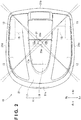
Fig. 2 is a plan view of the unmanned operation vehicle shown inFig. 1 ; -
Fig. 3 is an enlarged view of the central portion of the housing of the unmanned operation vehicle shown inFig. 2 ; -
Fig. 4 is a sectional view taken along a line 4 - 4 inFig. 3 ; and -
Fig. 5 is a plan view of a modification of the unmanned operation vehicle shown inFig. 1 . - Preferred embodiments to be described below are used to easily understand the present invention. Hence, those skilled in the art should remember that the present invention is not improperly limited by the embodiments to be explained below.
- As an example of an unmanned operation vehicle (to be referred to as an operation vehicle hereinafter) 10,
Figs. 1 and2 show an unmanned lawn mower (so-called robot lawn mower) capable of autonomously traveling to mow a lawn. Theoperation vehicle 10 includes ahousing 11, left and rightfront wheels 12 provided on the front side of thehousing 11, left and rightrear wheels 13 provided on the rear side of thehousing 11, and anoperation unit 14 provided on the lower side at the center of thehousing 11. In the example shown inFigs. 1 and2 , thelawn mowing blade 14 of therobot lawn mower 10 is shown as an example of theoperation unit 14. - The
housing 11 also serves as a bodywork. Thehousing 11 may include amain body portion 17, and alid portion 18 configured to open/close anopening portion 17a provided substantially at the center of themain body portion 17 in the plan view. Alternatively, thehousing 11 need not include thelid portion 18. Anouter periphery 21 of themain body portion 17 of thehousing 11 is formed into a substantially rectangular shape formed by afront edge 21a, arear edge 21b, aleft edge 21c, and aright edge 21d in the plan view. - The
lid portion 18 may have one end configured to engage with the end of themain body portion 17 on the side of theopening portion 17a, thereby vertically pivot about the engaging portion and opening/closing theopening portion 17a of themain body portion 17. Alternatively, thelid portion 18 may be configured to be detachable from themain body portion 17, thereby opening/closing theopening portion 17a of themain body portion 17. - The left and right
rear wheels 13 are individually driven by left andright drive motors 15. Theoperation unit 14 is driven by an operationunit drive motor 16. The left andright drive motors 15 and the operationunit drive motor 16 are a kind of power sources mounted in thehousing 11. - The
operation vehicle 10 also includes a control unit (not shown) that automatically controls the left andright drive motors 15 and the operationunit drive motor 16 based on detection signals from various kinds of detection sensors (not shown) and/or an image captured by a camera unit 31 (to be described later). The various kinds of detection sensors (not shown) are, for example, an obstacle detection sensor, an angular velocity sensor, and an acceleration sensor. When the left andright drive motors 15 rotate forward with the same speed or rotate backward with the same speed, theoperation vehicle 10 drives straight ahead in the front-and-rear direction. When only one of the left andright drive motors 15 rotates backward, theoperation vehicle 10 turns. - The
housing 11 has onecamera unit 31 that includes a plurality ofcameras 33 capable of capturing an image of the outside of theoperation vehicle 10 and is arranged substantially at the center of the upper surface of thehousing 11 in the plan view. If thehousing 11 includes thelid portion 18, thecamera unit 31 is arranged substantially at the center of the upper surface of thelid portion 18 in the plan view. If thehousing 11 includes thelid portion 18, thecamera unit 31 arranged on thelid portion 18 can be removed only by removing thelid portion 18. That is, the user need not individually remove thecamera unit 31 using, for example, a screwdriver in an exchange or inspection. - The reason why it is suitable to arrange the
camera unit 31 substantially at the center of the upper surface of thehousing 11 in the plan view will be described here. Thecamera unit 31 has the plurality ofcameras 33 on the outer periphery of thecamera unit 31. In the example shown inFigs. 2 and3 , thecamera unit 31 includes fourcameras 33, that is, afront camera 33a that captures an image on the front side of theoperation vehicle 10, arear camera 33b that captures an image on the rear side of theoperation vehicle 10, aleft camera 33c that captures an image on the left side of theoperation vehicle 10, and aright camera 33d that captures an image on the right side of theoperation vehicle 10. In the example shown inFigs. 2 and3 , the limiting lines of the imaging ranges of thecameras 33, which schematically represent the angles of view of thecameras 33, extend from thecameras 33 so as to facilitate an explanation of blind spots of the imaging ranges, that is, portions outside the imaging ranges of thecameras 33 provided in thecamera unit 31. -
Fig. 5 shows a comparative example in which the plurality ofcameras 33 are directly arranged on thehousing 11 without being integrated in thecamera unit 31. That is, in the comparative example shown inFig. 5 , thefront camera 33a is arranged on a side close to thefront edge 21a of themain body portion 17 of thehousing 11. Therear camera 33b is arranged on a side close to therear edge 21b of themain body portion 17. Theleft camera 33c is arranged on a side close to theleft edge 21a of themain body portion 17. Theright camera 33d is arranged on a side close to theright edge 21d of themain body portion 17. The angle of view of eachcamera 33 in the comparative example shown inFig. 5 is substantially the same as the angle of view of eachcamera 33 in the example shown inFig. 2 . - When
Figs. 2 and5 are compared, the blind spots of the imaging ranges of thecameras 33 are smaller in the example shown inFig. 2 . That is, when thecameras 33 are arranged substantially at the center of the upper surface of thehousing 11 in the plan view, the blind spots of the imaging ranges of thecameras 33 can be reduced without changing the number ofcameras 33, the arrangement positions of thecameras 33, and the angles of view of thecameras 33, as compared to a case in which thecameras 33 are arranged at positions far from the substantially center of the upper surface of thehousing 11 in the plan view. - As described above, on the
housing 11, the suitable position to arrange thecamera unit 31 is substantially at the center of the upper surface of thehousing 11 in the plan view. - Additionally, as shown in
Figs. 1 and4 , thehousing 11 is preferably formed such that the upper surface of thehousing 11 becomes highest substantially at the center in the plan view. Since the upper surface of thehousing 11 is highest substantially at the center of the upper surface in the plan view, inclusion of part of the upper surface of thehousing 11 in an image captured by eachcamera 33 is suppressed. - As in the example shown in
Fig. 2 , in at least the front half of the upper surface of thehousing 11, the limiting lines of the imaging ranges of thecameras 33 adjacent to each other in thecamera unit 31 viewed from the upper side preferably intersect on or inside theouter periphery 21 of thehousing 11. That is, in order to implement this, the number ofcameras 33, the arrangement positions of thecameras 33 on thecamera unit 31, and the angles of view of thecameras 33 are preferably appropriately selected. As a result, the blind spots of the imaging ranges of thecameras 33 are eliminated at least on the front side with respect to the center of the upper surface of thehousing 11, and thecamera unit 31 can suitably acquire information outside theoperation vehicle 10. - Additionally, as in the example shown in
Fig. 2 , in at least the rear half of the upper surface of thehousing 11, the limiting lines of the imaging ranges of thecameras 33 adjacent to each other in thecamera unit 31 viewed from the upper side preferably intersect on or inside theouter periphery 21 of thehousing 11. That is, in order to implement this, the number ofcameras 33, the arrangement positions of thecameras 33 on thecamera unit 31, and the angles of view of thecameras 33 are preferably appropriately selected. As a result, the blind spots of the imaging ranges of thecameras 33 are eliminated on the rear side with respect to the center of the upper surface of thehousing 11 as well, and thecamera unit 31 can suitably acquire information outside theoperation vehicle 10. - Since the
outer periphery 21 of themain body portion 17 of thehousing 11 is formed into a substantially rectangular shape in the plan view, the distances from the left and right corners of theouter periphery 21 on the front and rear sides to thecamera unit 31 are longer than the distances from thefront edge 21a, therear edge 21b, theleft edge 21c, and theright edge 21d of theouter periphery 21 to thecamera unit 31. For this reason, as compared to a case in which theouter periphery 21 has, for example, a substantially perfect circle shape in the plan view, the blind spots of the imaging ranges of thecameras 33 can be reduced without changing the angles of view of the cameras 33 (thefront camera 33a, therear camera 33b, theleft camera 33c, and theright camera 33d) provided in thecamera unit 31 in the example shown inFig. 2 . - In the example shown in
Fig. 2 , the distance from thefront edge 21a of theouter periphery 21 of themain body portion 17 of thehousing 11 to thecamera unit 31 is longer than the distance from therear edge 21b of theouter periphery 21 to thecamera unit 31. That is, the distances from the left and right corners of theouter periphery 21 on the front side (the corner between thefront edge 21a and theleft edge 21c and the corner between thefront edge 21a and theright edge 21d) to thecamera unit 31 are longer than the distances from the left and right corners on the rear side (the corner between therear edge 21b and theleft edge 21c and the corner between therear edge 21b and theright edge 21d) to thecamera unit 31. For this reason, as compared to a case in which, for example, the distance from thefront edge 21a of theouter periphery 21 of themain body portion 17 of thehousing 11 to thecamera unit 31 is shorter than the distance from therear edge 21b of theouter periphery 21 to thecamera unit 31, the blind spots of the imaging ranges of thecameras 33 can be reduced without changing the angles of view of thefront camera 33a, theleft camera 33c, and theright camera 33d provided in thecamera unit 31 in the example shown inFig. 2 . - In the embodiment described above, the
camera unit 31 including the plurality ofcameras 33 is arranged on thehousing 11. According to some embodiments, the plurality ofcameras 33 may directly be arranged on thehousing 11 without being integrated in thecamera unit 31. In this case, thecamera unit 31 is replaced with the plurality ofcameras 33 as needed in the above-described embodiment. Note that in a case in which the plurality ofcameras 33 are integrated in thesingle camera unit 31, the process and operation time for thehousing 11 to individually mount the plurality ofcamera 33 on thehousing 11 is unnecessary. - The present invention is not limited to the above-described exemplary embodiments, and those skilled in the art can easily change the above-described exemplary embodiments within the range included in the scope of the appended claims.
- The
operation vehicle 10 according to the present invention can suitably be employed as an unmanned operation vehicle capable of autonomously traveling. - 10...unmanned operation vehicle, 11...housing, 13...rear wheels, 14...operation unit, 15...drive motors, 16...operation unit drive motor, 17...main body portion of housing, 18...lid portion of housing, 31...camera unit, 33...camera
Claims (7)
- An unmanned operation vehicle comprising a housing, a self-propelled wheel provided in the housing, and an operation unit provided under the housing,
wherein the housing includes a plurality of cameras configured to capture an image of an outside of the unmanned operation vehicle, and
the plurality of cameras are arranged substantially at a center of an upper surface of the housing in a plan view. - The unmanned operation vehicle according to claim 1, wherein the housing comprises a single camera unit including the plurality of cameras.
- The unmanned operation vehicle according to claim 1 or 2, wherein the upper surface of the housing is highest substantially at the center of the upper surface of the housing in the plan view.
- The unmanned operation vehicle according to any one of claims 1 to 3, wherein an outer periphery of the housing is formed into a substantially rectangular shape formed by a front edge, a rear edge, a left edge, and a right edge in the plan view, and
the plurality of cameras comprise four cameras including a front camera configured to capture an image on a front side of the unmanned operation vehicle, a rear camera configured to capture an image on a rear side of the unmanned operation vehicle, a left camera configured to capture an image on a left side of the unmanned operation vehicle, and a right camera configured to capture an image on a right side of the unmanned operation vehicle. - The unmanned operation vehicle according to claim 4, wherein when the unmanned operation vehicle is viewed from an upper side, a distance from the front edge of the housing to the camera unit is longer than a distance from the rear edge of the housing to the camera unit.
- The unmanned operation vehicle according to any one of claims 1 to 5, wherein in at least a front half of the housing, when the plurality of cameras are viewed from the upper side, cameras adjacent to each other in the plurality of cameras are arranged such that limiting lines of imaging ranges of the cameras intersect on or inside the outer periphery of the housing.
- The unmanned operation vehicle according to claim 6, wherein not only in the front half of the housing but also in a rear half, when the camera unit is viewed from the upper side, cameras adjacent to each other in the plurality of cameras are arranged such that limiting lines of imaging ranges of the cameras intersect on or inside the outer periphery of the housing.
Applications Claiming Priority (1)
| Application Number | Priority Date | Filing Date | Title |
|---|---|---|---|
| PCT/JP2016/058554 WO2017158797A1 (en) | 2016-03-17 | 2016-03-17 | Unmanned traveling work vehicle |
Publications (3)
| Publication Number | Publication Date |
|---|---|
| EP3430879A1 true EP3430879A1 (en) | 2019-01-23 |
| EP3430879A4 EP3430879A4 (en) | 2019-02-27 |
| EP3430879B1 EP3430879B1 (en) | 2021-05-05 |
Family
ID=59851770
Family Applications (1)
| Application Number | Title | Priority Date | Filing Date |
|---|---|---|---|
| EP16894415.5A Active EP3430879B1 (en) | 2016-03-17 | 2016-03-17 | Unmanned traveling work vehicle |
Country Status (6)
| Country | Link |
|---|---|
| US (1) | US10725476B2 (en) |
| EP (1) | EP3430879B1 (en) |
| JP (1) | JP6654233B2 (en) |
| CN (1) | CN108777939B (en) |
| AU (1) | AU2016398123B2 (en) |
| WO (1) | WO2017158797A1 (en) |
Families Citing this family (3)
| Publication number | Priority date | Publication date | Assignee | Title |
|---|---|---|---|---|
| AU2016398123B2 (en) | 2016-03-17 | 2019-07-11 | Honda Motor Co., Ltd. | Unmanned Operation Vehicle |
| JP7184920B2 (en) * | 2018-10-31 | 2022-12-06 | 本田技研工業株式会社 | Autonomous work machine |
| WO2023181294A1 (en) * | 2022-03-24 | 2023-09-28 | 本田技研工業株式会社 | Autonomous work machine, autonomous work machine control method, program, and storage medium |
Family Cites Families (14)
| Publication number | Priority date | Publication date | Assignee | Title |
|---|---|---|---|---|
| JP3712276B2 (en) * | 1994-08-26 | 2005-11-02 | ソニー株式会社 | robot |
| JPH09167017A (en) * | 1995-12-15 | 1997-06-24 | Howa Mach Ltd | Driving control device for unmanned vehicles |
| JPH1034570A (en) * | 1996-07-19 | 1998-02-10 | Fujitsu Ltd | Robot remote control system |
| JP2008015692A (en) * | 2006-07-04 | 2008-01-24 | Toshiba Battery Co Ltd | Robot system |
| JP2009301175A (en) * | 2008-06-11 | 2009-12-24 | Ihi Aerospace Co Ltd | Monitoring method |
| DE102009028598A1 (en) | 2009-08-17 | 2011-03-03 | Robert Bosch Gmbh | Autonomous mobile platform for surface treatment |
| KR101850386B1 (en) * | 2011-04-19 | 2018-04-19 | 엘지전자 주식회사 | Robot cleaner and controlling method of the same |
| JP5461494B2 (en) * | 2011-09-14 | 2014-04-02 | ヤマハ発動機株式会社 | Automated traveling vehicle and control method for automated traveling vehicle |
| GB2500214A (en) * | 2012-03-13 | 2013-09-18 | Thomas Ladyman | Robot vision apparatus and control method and corresponding land robot |
| JP5550695B2 (en) * | 2012-09-21 | 2014-07-16 | 株式会社小松製作所 | Work vehicle periphery monitoring system and work vehicle |
| US9557740B2 (en) * | 2013-07-02 | 2017-01-31 | David Crawley | Autonomous mobile platform for service applications |
| WO2015144202A1 (en) * | 2014-03-24 | 2015-10-01 | Alfred Kärcher Gmbh & Co. Kg | Method for cleaning a floor surface and floor-cleaning device |
| EP3187953B1 (en) * | 2015-12-30 | 2020-03-18 | Honda Research Institute Europe GmbH | Autonomous working machine such as autonomous lawn mower |
| AU2016398123B2 (en) | 2016-03-17 | 2019-07-11 | Honda Motor Co., Ltd. | Unmanned Operation Vehicle |
-
2016
- 2016-03-17 AU AU2016398123A patent/AU2016398123B2/en not_active Ceased
- 2016-03-17 JP JP2018505169A patent/JP6654233B2/en not_active Expired - Fee Related
- 2016-03-17 WO PCT/JP2016/058554 patent/WO2017158797A1/en not_active Ceased
- 2016-03-17 CN CN201680082790.XA patent/CN108777939B/en not_active Expired - Fee Related
- 2016-03-17 EP EP16894415.5A patent/EP3430879B1/en active Active
-
2018
- 2018-08-23 US US16/109,933 patent/US10725476B2/en active Active
Also Published As
| Publication number | Publication date |
|---|---|
| US10725476B2 (en) | 2020-07-28 |
| CN108777939A (en) | 2018-11-09 |
| CN108777939B (en) | 2021-08-03 |
| WO2017158797A1 (en) | 2017-09-21 |
| AU2016398123A1 (en) | 2018-09-13 |
| EP3430879A4 (en) | 2019-02-27 |
| AU2016398123B2 (en) | 2019-07-11 |
| EP3430879B1 (en) | 2021-05-05 |
| JP6654233B2 (en) | 2020-02-26 |
| JPWO2017158797A1 (en) | 2018-12-27 |
| US20180364729A1 (en) | 2018-12-20 |
Similar Documents
| Publication | Publication Date | Title |
|---|---|---|
| EP3430880B1 (en) | Unmanned traveling work vehicle | |
| US10558221B2 (en) | Method for assisting in a parking operation for a motor vehicle, driver assistance system and a motor vehicle | |
| EP3223101B1 (en) | Automatic operation vehicle | |
| US10725476B2 (en) | Unmanned operation vehicle | |
| US10068141B2 (en) | Automatic operation vehicle | |
| WO2016093311A1 (en) | Work vehicle | |
| CN114341930A (en) | Image processing device, imaging device, robot, and robot system | |
| EP3223102B1 (en) | Automatic operation vehicle | |
| JP7321911B2 (en) | work machine | |
| EP3770808B1 (en) | PUBLIC TRANSPORT VEHICLE EQUIPPED WITH A SAFETY SYSTEM | |
| JP2019144849A (en) | Autonomous traveling cleaner |
Legal Events
| Date | Code | Title | Description |
|---|---|---|---|
| STAA | Information on the status of an ep patent application or granted ep patent |
Free format text: STATUS: THE INTERNATIONAL PUBLICATION HAS BEEN MADE |
|
| PUAI | Public reference made under article 153(3) epc to a published international application that has entered the european phase |
Free format text: ORIGINAL CODE: 0009012 |
|
| STAA | Information on the status of an ep patent application or granted ep patent |
Free format text: STATUS: REQUEST FOR EXAMINATION WAS MADE |
|
| 17P | Request for examination filed |
Effective date: 20180827 |
|
| AK | Designated contracting states |
Kind code of ref document: A1 Designated state(s): AL AT BE BG CH CY CZ DE DK EE ES FI FR GB GR HR HU IE IS IT LI LT LU LV MC MK MT NL NO PL PT RO RS SE SI SK SM TR |
|
| AX | Request for extension of the european patent |
Extension state: BA ME |
|
| REG | Reference to a national code |
Ref country code: DE Ref legal event code: R079 Ref document number: 602016057616 Country of ref document: DE Free format text: PREVIOUS MAIN CLASS: A01D0034640000 Ipc: A01D0034000000 |
|
| A4 | Supplementary search report drawn up and despatched |
Effective date: 20190130 |
|
| RIC1 | Information provided on ipc code assigned before grant |
Ipc: G05D 1/02 20060101ALI20190124BHEP Ipc: A01D 34/00 20060101AFI20190124BHEP Ipc: A01B 69/00 20060101ALI20190124BHEP |
|
| DAV | Request for validation of the european patent (deleted) | ||
| DAX | Request for extension of the european patent (deleted) | ||
| STAA | Information on the status of an ep patent application or granted ep patent |
Free format text: STATUS: EXAMINATION IS IN PROGRESS |
|
| 17Q | First examination report despatched |
Effective date: 20200406 |
|
| GRAP | Despatch of communication of intention to grant a patent |
Free format text: ORIGINAL CODE: EPIDOSNIGR1 |
|
| STAA | Information on the status of an ep patent application or granted ep patent |
Free format text: STATUS: GRANT OF PATENT IS INTENDED |
|
| INTG | Intention to grant announced |
Effective date: 20201204 |
|
| GRAS | Grant fee paid |
Free format text: ORIGINAL CODE: EPIDOSNIGR3 |
|
| GRAA | (expected) grant |
Free format text: ORIGINAL CODE: 0009210 |
|
| STAA | Information on the status of an ep patent application or granted ep patent |
Free format text: STATUS: THE PATENT HAS BEEN GRANTED |
|
| AK | Designated contracting states |
Kind code of ref document: B1 Designated state(s): AL AT BE BG CH CY CZ DE DK EE ES FI FR GB GR HR HU IE IS IT LI LT LU LV MC MK MT NL NO PL PT RO RS SE SI SK SM TR |
|
| REG | Reference to a national code |
Ref country code: GB Ref legal event code: FG4D |
|
| REG | Reference to a national code |
Ref country code: CH Ref legal event code: EP |
|
| REG | Reference to a national code |
Ref country code: AT Ref legal event code: REF Ref document number: 1388637 Country of ref document: AT Kind code of ref document: T Effective date: 20210515 |
|
| REG | Reference to a national code |
Ref country code: IE Ref legal event code: FG4D |
|
| REG | Reference to a national code |
Ref country code: DE Ref legal event code: R096 Ref document number: 602016057616 Country of ref document: DE |
|
| REG | Reference to a national code |
Ref country code: LT Ref legal event code: MG9D |
|
| REG | Reference to a national code |
Ref country code: AT Ref legal event code: MK05 Ref document number: 1388637 Country of ref document: AT Kind code of ref document: T Effective date: 20210505 |
|
| PG25 | Lapsed in a contracting state [announced via postgrant information from national office to epo] |
Ref country code: BG Free format text: LAPSE BECAUSE OF FAILURE TO SUBMIT A TRANSLATION OF THE DESCRIPTION OR TO PAY THE FEE WITHIN THE PRESCRIBED TIME-LIMIT Effective date: 20210805 Ref country code: AT Free format text: LAPSE BECAUSE OF FAILURE TO SUBMIT A TRANSLATION OF THE DESCRIPTION OR TO PAY THE FEE WITHIN THE PRESCRIBED TIME-LIMIT Effective date: 20210505 Ref country code: HR Free format text: LAPSE BECAUSE OF FAILURE TO SUBMIT A TRANSLATION OF THE DESCRIPTION OR TO PAY THE FEE WITHIN THE PRESCRIBED TIME-LIMIT Effective date: 20210505 Ref country code: FI Free format text: LAPSE BECAUSE OF FAILURE TO SUBMIT A TRANSLATION OF THE DESCRIPTION OR TO PAY THE FEE WITHIN THE PRESCRIBED TIME-LIMIT Effective date: 20210505 Ref country code: LT Free format text: LAPSE BECAUSE OF FAILURE TO SUBMIT A TRANSLATION OF THE DESCRIPTION OR TO PAY THE FEE WITHIN THE PRESCRIBED TIME-LIMIT Effective date: 20210505 |
|
| PG25 | Lapsed in a contracting state [announced via postgrant information from national office to epo] |
Ref country code: PT Free format text: LAPSE BECAUSE OF FAILURE TO SUBMIT A TRANSLATION OF THE DESCRIPTION OR TO PAY THE FEE WITHIN THE PRESCRIBED TIME-LIMIT Effective date: 20210906 Ref country code: PL Free format text: LAPSE BECAUSE OF FAILURE TO SUBMIT A TRANSLATION OF THE DESCRIPTION OR TO PAY THE FEE WITHIN THE PRESCRIBED TIME-LIMIT Effective date: 20210505 Ref country code: NO Free format text: LAPSE BECAUSE OF FAILURE TO SUBMIT A TRANSLATION OF THE DESCRIPTION OR TO PAY THE FEE WITHIN THE PRESCRIBED TIME-LIMIT Effective date: 20210805 Ref country code: SE Free format text: LAPSE BECAUSE OF FAILURE TO SUBMIT A TRANSLATION OF THE DESCRIPTION OR TO PAY THE FEE WITHIN THE PRESCRIBED TIME-LIMIT Effective date: 20210505 Ref country code: RS Free format text: LAPSE BECAUSE OF FAILURE TO SUBMIT A TRANSLATION OF THE DESCRIPTION OR TO PAY THE FEE WITHIN THE PRESCRIBED TIME-LIMIT Effective date: 20210505 Ref country code: GR Free format text: LAPSE BECAUSE OF FAILURE TO SUBMIT A TRANSLATION OF THE DESCRIPTION OR TO PAY THE FEE WITHIN THE PRESCRIBED TIME-LIMIT Effective date: 20210806 Ref country code: LV Free format text: LAPSE BECAUSE OF FAILURE TO SUBMIT A TRANSLATION OF THE DESCRIPTION OR TO PAY THE FEE WITHIN THE PRESCRIBED TIME-LIMIT Effective date: 20210505 Ref country code: IS Free format text: LAPSE BECAUSE OF FAILURE TO SUBMIT A TRANSLATION OF THE DESCRIPTION OR TO PAY THE FEE WITHIN THE PRESCRIBED TIME-LIMIT Effective date: 20210905 |
|
| REG | Reference to a national code |
Ref country code: NL Ref legal event code: MP Effective date: 20210505 |
|
| PG25 | Lapsed in a contracting state [announced via postgrant information from national office to epo] |
Ref country code: NL Free format text: LAPSE BECAUSE OF FAILURE TO SUBMIT A TRANSLATION OF THE DESCRIPTION OR TO PAY THE FEE WITHIN THE PRESCRIBED TIME-LIMIT Effective date: 20210505 |
|
| PG25 | Lapsed in a contracting state [announced via postgrant information from national office to epo] |
Ref country code: SK Free format text: LAPSE BECAUSE OF FAILURE TO SUBMIT A TRANSLATION OF THE DESCRIPTION OR TO PAY THE FEE WITHIN THE PRESCRIBED TIME-LIMIT Effective date: 20210505 Ref country code: SM Free format text: LAPSE BECAUSE OF FAILURE TO SUBMIT A TRANSLATION OF THE DESCRIPTION OR TO PAY THE FEE WITHIN THE PRESCRIBED TIME-LIMIT Effective date: 20210505 Ref country code: RO Free format text: LAPSE BECAUSE OF FAILURE TO SUBMIT A TRANSLATION OF THE DESCRIPTION OR TO PAY THE FEE WITHIN THE PRESCRIBED TIME-LIMIT Effective date: 20210505 Ref country code: ES Free format text: LAPSE BECAUSE OF FAILURE TO SUBMIT A TRANSLATION OF THE DESCRIPTION OR TO PAY THE FEE WITHIN THE PRESCRIBED TIME-LIMIT Effective date: 20210505 Ref country code: DK Free format text: LAPSE BECAUSE OF FAILURE TO SUBMIT A TRANSLATION OF THE DESCRIPTION OR TO PAY THE FEE WITHIN THE PRESCRIBED TIME-LIMIT Effective date: 20210505 Ref country code: CZ Free format text: LAPSE BECAUSE OF FAILURE TO SUBMIT A TRANSLATION OF THE DESCRIPTION OR TO PAY THE FEE WITHIN THE PRESCRIBED TIME-LIMIT Effective date: 20210505 Ref country code: EE Free format text: LAPSE BECAUSE OF FAILURE TO SUBMIT A TRANSLATION OF THE DESCRIPTION OR TO PAY THE FEE WITHIN THE PRESCRIBED TIME-LIMIT Effective date: 20210505 |
|
| REG | Reference to a national code |
Ref country code: DE Ref legal event code: R097 Ref document number: 602016057616 Country of ref document: DE |
|
| PLBE | No opposition filed within time limit |
Free format text: ORIGINAL CODE: 0009261 |
|
| STAA | Information on the status of an ep patent application or granted ep patent |
Free format text: STATUS: NO OPPOSITION FILED WITHIN TIME LIMIT |
|
| 26N | No opposition filed |
Effective date: 20220208 |
|
| PG25 | Lapsed in a contracting state [announced via postgrant information from national office to epo] |
Ref country code: IS Free format text: LAPSE BECAUSE OF FAILURE TO SUBMIT A TRANSLATION OF THE DESCRIPTION OR TO PAY THE FEE WITHIN THE PRESCRIBED TIME-LIMIT Effective date: 20210905 Ref country code: AL Free format text: LAPSE BECAUSE OF FAILURE TO SUBMIT A TRANSLATION OF THE DESCRIPTION OR TO PAY THE FEE WITHIN THE PRESCRIBED TIME-LIMIT Effective date: 20210505 |
|
| PGFP | Annual fee paid to national office [announced via postgrant information from national office to epo] |
Ref country code: FR Payment date: 20220322 Year of fee payment: 7 |
|
| PG25 | Lapsed in a contracting state [announced via postgrant information from national office to epo] |
Ref country code: IT Free format text: LAPSE BECAUSE OF FAILURE TO SUBMIT A TRANSLATION OF THE DESCRIPTION OR TO PAY THE FEE WITHIN THE PRESCRIBED TIME-LIMIT Effective date: 20210505 |
|
| REG | Reference to a national code |
Ref country code: DE Ref legal event code: R084 Ref document number: 602016057616 Country of ref document: DE |
|
| PG25 | Lapsed in a contracting state [announced via postgrant information from national office to epo] |
Ref country code: MC Free format text: LAPSE BECAUSE OF FAILURE TO SUBMIT A TRANSLATION OF THE DESCRIPTION OR TO PAY THE FEE WITHIN THE PRESCRIBED TIME-LIMIT Effective date: 20210505 |
|
| REG | Reference to a national code |
Ref country code: CH Ref legal event code: PL |
|
| GBPC | Gb: european patent ceased through non-payment of renewal fee |
Effective date: 20220317 |
|
| REG | Reference to a national code |
Ref country code: BE Ref legal event code: MM Effective date: 20220331 |
|
| PG25 | Lapsed in a contracting state [announced via postgrant information from national office to epo] |
Ref country code: LU Free format text: LAPSE BECAUSE OF NON-PAYMENT OF DUE FEES Effective date: 20220317 Ref country code: LI Free format text: LAPSE BECAUSE OF NON-PAYMENT OF DUE FEES Effective date: 20220331 Ref country code: IE Free format text: LAPSE BECAUSE OF NON-PAYMENT OF DUE FEES Effective date: 20220317 Ref country code: GB Free format text: LAPSE BECAUSE OF NON-PAYMENT OF DUE FEES Effective date: 20220317 Ref country code: CH Free format text: LAPSE BECAUSE OF NON-PAYMENT OF DUE FEES Effective date: 20220331 |
|
| PG25 | Lapsed in a contracting state [announced via postgrant information from national office to epo] |
Ref country code: BE Free format text: LAPSE BECAUSE OF NON-PAYMENT OF DUE FEES Effective date: 20220331 |
|
| PG25 | Lapsed in a contracting state [announced via postgrant information from national office to epo] |
Ref country code: FR Free format text: LAPSE BECAUSE OF NON-PAYMENT OF DUE FEES Effective date: 20230331 |
|
| PG25 | Lapsed in a contracting state [announced via postgrant information from national office to epo] |
Ref country code: HU Free format text: LAPSE BECAUSE OF FAILURE TO SUBMIT A TRANSLATION OF THE DESCRIPTION OR TO PAY THE FEE WITHIN THE PRESCRIBED TIME-LIMIT; INVALID AB INITIO Effective date: 20160317 |
|
| PG25 | Lapsed in a contracting state [announced via postgrant information from national office to epo] |
Ref country code: MK Free format text: LAPSE BECAUSE OF FAILURE TO SUBMIT A TRANSLATION OF THE DESCRIPTION OR TO PAY THE FEE WITHIN THE PRESCRIBED TIME-LIMIT Effective date: 20210505 Ref country code: CY Free format text: LAPSE BECAUSE OF FAILURE TO SUBMIT A TRANSLATION OF THE DESCRIPTION OR TO PAY THE FEE WITHIN THE PRESCRIBED TIME-LIMIT Effective date: 20210505 |
|
| PG25 | Lapsed in a contracting state [announced via postgrant information from national office to epo] |
Ref country code: TR Free format text: LAPSE BECAUSE OF FAILURE TO SUBMIT A TRANSLATION OF THE DESCRIPTION OR TO PAY THE FEE WITHIN THE PRESCRIBED TIME-LIMIT Effective date: 20210505 |
|
| PG25 | Lapsed in a contracting state [announced via postgrant information from national office to epo] |
Ref country code: MT Free format text: LAPSE BECAUSE OF FAILURE TO SUBMIT A TRANSLATION OF THE DESCRIPTION OR TO PAY THE FEE WITHIN THE PRESCRIBED TIME-LIMIT Effective date: 20210505 |
|
| PGFP | Annual fee paid to national office [announced via postgrant information from national office to epo] |
Ref country code: DE Payment date: 20260219 Year of fee payment: 11 |