EP3430427B1 - Processing method of a 3d point cloud - Google Patents
Processing method of a 3d point cloud Download PDFInfo
- Publication number
- EP3430427B1 EP3430427B1 EP17710902.2A EP17710902A EP3430427B1 EP 3430427 B1 EP3430427 B1 EP 3430427B1 EP 17710902 A EP17710902 A EP 17710902A EP 3430427 B1 EP3430427 B1 EP 3430427B1
- Authority
- EP
- European Patent Office
- Prior art keywords
- data
- point
- spaces
- channel
- space
- Prior art date
- Legal status (The legal status is an assumption and is not a legal conclusion. Google has not performed a legal analysis and makes no representation as to the accuracy of the status listed.)
- Active
Links
Images


Classifications
-
- G—PHYSICS
- G01—MEASURING; TESTING
- G01S—RADIO DIRECTION-FINDING; RADIO NAVIGATION; DETERMINING DISTANCE OR VELOCITY BY USE OF RADIO WAVES; LOCATING OR PRESENCE-DETECTING BY USE OF THE REFLECTION OR RERADIATION OF RADIO WAVES; ANALOGOUS ARRANGEMENTS USING OTHER WAVES
- G01S17/00—Systems using the reflection or reradiation of electromagnetic waves other than radio waves, e.g. lidar systems
- G01S17/88—Lidar systems specially adapted for specific applications
- G01S17/89—Lidar systems specially adapted for specific applications for mapping or imaging
-
- G—PHYSICS
- G01—MEASURING; TESTING
- G01S—RADIO DIRECTION-FINDING; RADIO NAVIGATION; DETERMINING DISTANCE OR VELOCITY BY USE OF RADIO WAVES; LOCATING OR PRESENCE-DETECTING BY USE OF THE REFLECTION OR RERADIATION OF RADIO WAVES; ANALOGOUS ARRANGEMENTS USING OTHER WAVES
- G01S17/00—Systems using the reflection or reradiation of electromagnetic waves other than radio waves, e.g. lidar systems
- G01S17/88—Lidar systems specially adapted for specific applications
- G01S17/93—Lidar systems specially adapted for specific applications for anti-collision purposes
- G01S17/931—Lidar systems specially adapted for specific applications for anti-collision purposes of land vehicles
-
- G—PHYSICS
- G01—MEASURING; TESTING
- G01S—RADIO DIRECTION-FINDING; RADIO NAVIGATION; DETERMINING DISTANCE OR VELOCITY BY USE OF RADIO WAVES; LOCATING OR PRESENCE-DETECTING BY USE OF THE REFLECTION OR RERADIATION OF RADIO WAVES; ANALOGOUS ARRANGEMENTS USING OTHER WAVES
- G01S7/00—Details of systems according to groups G01S13/00, G01S15/00, G01S17/00
- G01S7/48—Details of systems according to groups G01S13/00, G01S15/00, G01S17/00 of systems according to group G01S17/00
- G01S7/4802—Details of systems according to groups G01S13/00, G01S15/00, G01S17/00 of systems according to group G01S17/00 using analysis of echo signal for target characterisation; Target signature; Target cross-section
-
- G—PHYSICS
- G01—MEASURING; TESTING
- G01S—RADIO DIRECTION-FINDING; RADIO NAVIGATION; DETERMINING DISTANCE OR VELOCITY BY USE OF RADIO WAVES; LOCATING OR PRESENCE-DETECTING BY USE OF THE REFLECTION OR RERADIATION OF RADIO WAVES; ANALOGOUS ARRANGEMENTS USING OTHER WAVES
- G01S7/00—Details of systems according to groups G01S13/00, G01S15/00, G01S17/00
- G01S7/48—Details of systems according to groups G01S13/00, G01S15/00, G01S17/00 of systems according to group G01S17/00
- G01S7/4808—Evaluating distance, position or velocity data
-
- G—PHYSICS
- G06—COMPUTING OR CALCULATING; COUNTING
- G06F—ELECTRIC DIGITAL DATA PROCESSING
- G06F18/00—Pattern recognition
- G06F18/20—Analysing
- G06F18/24—Classification techniques
- G06F18/241—Classification techniques relating to the classification model, e.g. parametric or non-parametric approaches
- G06F18/2413—Classification techniques relating to the classification model, e.g. parametric or non-parametric approaches based on distances to training or reference patterns
-
- G—PHYSICS
- G06—COMPUTING OR CALCULATING; COUNTING
- G06T—IMAGE DATA PROCESSING OR GENERATION, IN GENERAL
- G06T7/00—Image analysis
- G06T7/50—Depth or shape recovery
- G06T7/521—Depth or shape recovery from laser ranging, e.g. using interferometry; from the projection of structured light
-
- G—PHYSICS
- G06—COMPUTING OR CALCULATING; COUNTING
- G06V—IMAGE OR VIDEO RECOGNITION OR UNDERSTANDING
- G06V10/00—Arrangements for image or video recognition or understanding
- G06V10/20—Image preprocessing
- G06V10/32—Normalisation of the pattern dimensions
-
- G—PHYSICS
- G06—COMPUTING OR CALCULATING; COUNTING
- G06V—IMAGE OR VIDEO RECOGNITION OR UNDERSTANDING
- G06V10/00—Arrangements for image or video recognition or understanding
- G06V10/70—Arrangements for image or video recognition or understanding using pattern recognition or machine learning
- G06V10/764—Arrangements for image or video recognition or understanding using pattern recognition or machine learning using classification, e.g. of video objects
-
- G—PHYSICS
- G06—COMPUTING OR CALCULATING; COUNTING
- G06V—IMAGE OR VIDEO RECOGNITION OR UNDERSTANDING
- G06V10/00—Arrangements for image or video recognition or understanding
- G06V10/70—Arrangements for image or video recognition or understanding using pattern recognition or machine learning
- G06V10/82—Arrangements for image or video recognition or understanding using pattern recognition or machine learning using neural networks
-
- G—PHYSICS
- G06—COMPUTING OR CALCULATING; COUNTING
- G06V—IMAGE OR VIDEO RECOGNITION OR UNDERSTANDING
- G06V20/00—Scenes; Scene-specific elements
- G06V20/50—Context or environment of the image
- G06V20/56—Context or environment of the image exterior to a vehicle by using sensors mounted on the vehicle
- G06V20/58—Recognition of moving objects or obstacles, e.g. vehicles or pedestrians; Recognition of traffic objects, e.g. traffic signs, traffic lights or roads
-
- G—PHYSICS
- G06—COMPUTING OR CALCULATING; COUNTING
- G06V—IMAGE OR VIDEO RECOGNITION OR UNDERSTANDING
- G06V20/00—Scenes; Scene-specific elements
- G06V20/60—Type of objects
- G06V20/64—Three-dimensional [3D] objects
-
- G—PHYSICS
- G06—COMPUTING OR CALCULATING; COUNTING
- G06T—IMAGE DATA PROCESSING OR GENERATION, IN GENERAL
- G06T2207/00—Indexing scheme for image analysis or image enhancement
- G06T2207/10—Image acquisition modality
- G06T2207/10028—Range image; Depth image; 3D point clouds
-
- G—PHYSICS
- G06—COMPUTING OR CALCULATING; COUNTING
- G06T—IMAGE DATA PROCESSING OR GENERATION, IN GENERAL
- G06T2207/00—Indexing scheme for image analysis or image enhancement
- G06T2207/20—Special algorithmic details
- G06T2207/20081—Training; Learning
Definitions
- the present invention relates to automated driving of vehicles.
- the present invention relates to a processing method of a three-dimensional (3D) point cloud derived using a Lidar or the like. It further relates to a method for classification of an object of interest within a 3D point cloud based on such processing method and using machine learning.
- a Lidar sensor measures distance by illuminating a target with a laser light.
- Document EP 2 958 049 A2 describes a method of extracting feature regions from point cloud.
- the described method uses hand-crafted process for key point selection and descriptor computation for corresponding voxel, which is later classified by machine learning algorithm.
- Such processing pipeline where features are pre-selected, could not let Deep Neural Network (DNN) to realize its potential in automatically finding features since significant part of the information was pre-filtered due to the choice of hand-crafted methods.
- DNN Deep Neural Network
- Such pre-filtering could be beneficial for certain types of situations, while penalizing in many other real world situations.
- the described method does not compensate for low density of point cloud data, therefore having lower recognition accuracy for objects at far distance.
- the described method uses intensity up to 7.5 m at 850nm wavelength. Further, the described method is based on a feature engineering approach, where all features are handcrafted so that the way how data is combined remained unchangeable independently of training data. It never uses combination of intensity and 3D information to form features for object recognition, but uses instead either 3D data or either 2D data processing consequently, while by having direct correspondence between intensity value and 3D measurement for each pixel. Furthermore, the described method uses intensity to filter noise during segmentation of regions of interest to improve 3D obstacle clustering. More particularly, the described method uses 4 separate channels I, X, Y, Z, which forms several spaces and cannot be processed easily and efficiently by convolution deep neural networks without additional processing stage.
- the present invention aims to address the above mentioned drawbacks of the prior art, and to propose first a processing method of a 3D point cloud which is simple and adapted for machine learning purposes and a method of classification of an object of interest within a 3D point cloud based on such processing method and using machine learning.
- a first aspect of the invention is a processing method of a three-dimensional (3D) point cloud, comprising the steps of:
- the processing method according to the above embodiment of the invention provides a simple and easy way to transform the obtained 3D point cloud data into a single multi-channel 2D space defined by at least three 2D spaces including information on the intensity, the elevation and distance which allows to keep all essential information in order to recognize any object of interest within the 3D point cloud.
- having an intensity space from the depth sensor intensity data brings additional source of information useful to classify objects made from different materials.
- such single multi-channel 2D space is well adapted to machine learning algorithm and only needs to use a single depth sensor which is at lower cost compared to fusion of sensors and produces (time series of point clouds with 3D coordinates and intensity data with the same signal/noise ratio for all day/night and weather conditions.
- the transforming step further includes the steps of detecting background points and setting a predetermined default value for detected background points.
- Background points which are detected thanks to their coordinates and intensity values, are set to a fixed value (e.g. 0, 0, 0) within the different 2D spaces. Therefore, foreground points (non-background) which are also transformed into 2D spaces would then not occupy them entirely. Indeed in the resulting 2D spaces, background points would be empty.
- the chosen default value should be different from values of points projected into 2D spaces for each space/channel. We experimented with different values and find out that the fixed default value (0,0,0) provides highest resulting accuracy. Furthermore, machine learning would then be able to use background/foreground information to learn outside shape or contours of objects of interest.
- the processing method includes a training phase during which it further comprises before the transforming step, the steps of:
- Such labelling step ensures that during the training phase, objects of interest within the 3D point cloud are correctly assigned to the corresponding tags. It also shortens such training phase and increases reliability of classification during online phase.
- the transforming step includes a normalizing step of at least one of the 2D spaces, which consists in:
- the 3D point cloud is derived using a depth sensor such as a Lidar.
- a depth sensor such as a Lidar
- Using a single depth sensor such as a Lidar to define the single multi-channel 2D space proves to be more economical and easy to integrate in particular as regards the produced data format.
- each of the intensity 2D space, the height 2D space and the distance 2D space is respectively assigned to one of RGB (red, green, blue) value spaces for each point.
- RGB red, green, blue
- a second aspect of the invention is a method for classification of an object of interest within a 3D point cloud, comprising the steps of:
- the classification method according to the above embodiment of the invention provides a method that merges at least three different sources of information, namely intensity, height and distance together in the form of merged (normalized) 2D spaces defining a (normalized) single multi-channel 2D space which is a very efficient way to communicate this information for any machine learning.
- single multi-channel 2D space can be used as entry for parallel processing chain of machine learning such as convolution or deep neural networks. With parallel access and processing of such merged 2D spaces, i.e.
- the supplying step consists in:
- Such supplying variants using time series of data (accumulated batch) combined into one or several multi-channel 2D spaces is useful during the training stage in particular to compensate for low density of data at far distances and therefore allowing DNN to access more information and select more robust features/patterns resulting in a higher recognition accuracy for objects at far distance compared to prior art methods which does not compensate for low density of point cloud data.
- a trained DNN benefits from the training phase to be able to accurately recognize stable patterns even if it receives low density of point data.
- the present invention further relates to a vehicle comprising:
- the methods according to the present invention are according to a first aspect a processing method to transform a three-dimensional (3D) point cloud obtained by a depth sensor (e.g. Lidar) into one single or several multi-channel 2D spaces and according to a second aspect a method for classification of an object of interest within a 3D point cloud using machine learning (e.g. deep neural network) supplied by one or more multi-channel 2D spaces obtained by the processing method.
- a depth sensor e.g. Lidar
- machine learning e.g. deep neural network
- This method of classification comprises a learning phase during which a deep neural network (DNN) learns all possible useful patterns to classify and recognize object of interest within a 3D point cloud based on as much as possible data supplied in the format of multi-channel 2D spaces and an online phase during which the DNN classifies object of interests recognized within 3D point cloud data supplied in the form of a single multi-channel 2D spaces.
- DNN deep neural network
- 3D point cloud outputs from the Lidar sensor provides the necessary data for a robot software including both of these methods to promptly and accurately determine where potential obstacles exist in the environment.
- the processing method comprises four stages A to D.
- Stage A is an acquisition stage of 3D point cloud data using a depth sensor such as a Lidar.
- Stage B is a projection stage also called transformation stage where 3D point cloud data are projected or transformed into several 2D spaces.
- Stage C is an optional stage where the 2D spaces obtained at stage B are normalized to get uniform data.
- stage D defines and combines several kinds of multi-channel 2D spaces to be further supplied to a machine learning.
- the depth sensor used is preferably a Lidar sensor of the scanning laser range finder kind.
- This Lidar sensor scans its environment with a laser beam and measures for each point scanned its distance from the Lidar sensor view point as well as its intensity, allowing the reconstruction of a three-dimensional model of the scene in the form of a 3D point cloud (Data-A) at time T comprising 3D coordinates (xyz) and intensity data (i) for each point of the cloud with respect to the view point of the Lidar sensor.
- Data-A 3D point cloud
- Lidar sensor An example of Lidar sensor that can be used is the Velodyne lidar sensor HDL-64E (http://velodvnelidar.com/docs/datasheet/63-9194 Rev-D HDL-64E Data%20Sheet Web.pdf).
- This Lidar sensor uses 64 fixed-mounted lasers to measure the surrounding environment, each mechanically mounted to a specific vertical angle, with the entire unit spinning. This approach dramatically increases reliability, field of view (FOV), and point cloud density.
- the capture frequency of 3D point cloud is preferably between 10 and 15 Hz allowing to capture point cloud time series up to 120m at 905nm wavelenght.
- tags data classifying objects in 1:N classes is supplied so that obtained 3D point cloud data (Data-A) are tagged as belonging to objects of 1:N classes based on supplied tags data (Label-A).
- Stage A output corresponds to tagged point could data (Data-A and Label-A) being decomposed into 3D coordinates relative to the view point and intensity value for each point.
- Stage B (tagged) 3D point cloud data (Data-A) is inputted.
- Data-A 3D coordinates (xyz) and intensity (i) data are projected into three different 2D image spaces, namely an intensity 2D space (IS), a height 2D space (HS) and a distance 2D space (DS).
- IS intensity 2D space
- HS height 2D space
- DS distance 2D space
- a projection matrix 3D to 2D defined to reproduced a 2D image corresponding to the view point of the Lidar sensor.
- a transformation matrix of the perspective projection type https://en.wikipedia.org/wiki/Transformation matrix#Perspective projection.
- the intensity 2D space is defined as a function of the intensity (i) data of each point within the 3D point cloud.
- Such function can be very simple as for example a direct transposition of the intensity data into the 2D space or more complex depending also on the distance data.
- the height 2D space is defined herewith as a function of an elevation data (h) linked to the z coordinate of each point with respect to the view point.
- the distance 2D space is defined as a function of the distance (d) data between each point and the view point linked to the xyz coordinates. Such distance space aims to only reflect points from the point cloud that can be seen from the view point.
- background points which are detected thanks to their distance and intensity values, are set to a fixed value (zero) within the different 2D spaces in order to be excluded from the machine learning.
- Stage B output corresponds to three 2D spaces including an intensity, height and distance 2D spaces (Data-B) defining a single multi-channel 2D space.
- Data-B distance 2D spaces
- Stage C the three 2D spaces (Data-B) are inputted. This stage is used to normalize all 2D spaces and renders uniform data. This normalization is done according to min and max values or any other adequate complex function, so that data represents relative changes of intensity, height and distance within point cloud at time T.
- the normalized intensity 2D space is obtained by applying an intensity normalizing function depending on the distance data to the intensity data of each point.
- An example of complex function is the normalization of intensity as function of the distance of the object as given in Velodyne user's manual and programming guide HDL-64E S3 "High Definition LiDAR Sensor" (see p. 45). http://velodvnelidar.com/docs/manuals/63-HDL64ES3g%20USERS%20MANUAL PROGRAM%20GUIDE,%20HDL-64E%20S3.pdf)
- the normalized height 2D space is obtained by applying a height normalizing function depending on the minimum and maximum elevation data within the 3D point cloud to the elevation data of each point.
- the normalized distance 2D space is obtained by applying a distance normalizing function depending on the minimum and maximum distance data within the 3D point cloud to the distance data of each point.
- Stage C output corresponds to normalized three 2D spaces (Data-C) defining a single normalized multi-channel 2D space.
- Stage D the normalized three 2D spaces (Data-C) are inputted.
- stage D defines and combines several kinds of (normalized) multi-channel 2D spaces (Data-D) to be further supplied to a machine learning as it will be explained in relation with Figure 2 .
- Several examples of multi-channel 2D spaces will be presented in more details with Figures 3A-3D .
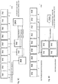
- FIGS 3A-3D illustrate four examples of data combination outputted from Stage D to be supplied to the machine learning (Stage E, figure 2 ).
- Each figure shows an original time sequence of nine consecutive single multi-channel 2D spaces (ihd) corresponding to an accumulated batch of data inputted to Stage D (Data-C).
- Each 2D space is an array of 64x64 pixels, so that each single multi-channel 2D space (ihd) is an array of 64x64x3.
- Stage D output corresponds to the last single multi-channel 2D space (ihd 9). Such straight selection of the last single fixed position is preferably used during online phases when responsiveness from the machine learning is needed.
- Data-D format is the same as a single multi-channel 2D space, that is to say 64x64x3.
- Stage D output corresponds to an average combination of a random number of multi-channel 2D spaces among the original time sequence. Such average combination is preferably used during training phases of the machine learning in order to supply data based on more information (ihd 1-9). In the illustrated example, 6 out of 9 multi-channel 2D space are randomly selected (e.g. 2, 1, 5, 9, 6, 4). Data-D format is the same as a single multi-channel 2D space, that is to say 64x64x3.
- Stage D output corresponds to several multi-channel 2D spaces (ihd slices) distributed in a predefined order among the original time sequence. Such slice combination is also preferably used during training phases of the machine learning in order to supply more data (3 ihds) based on more information (ihd 1-9).
- first (ihd 1), medium (ihd 5) and last (ihd 9) multi-channel 2D space are selected.
- Data-D format is three times 64x64x3.
- Stage D output corresponds to a matrix of at least 2x2 multi-channel 2D spaces randomly selected among the original time sequence.
- Such matrix combination is also preferably used during training phases of the machine learning in order to supply more data (4 ihds) based on more information (ihd 1-9).
- four ihds (ihd 3, 6, 7, 8) out of 9 are randomly selected.
- Data-D format is 128x128x3.
- Figure 2 illustrates a preferred method for classification of an object of interest within a 3D point cloud based on the processing method presented in relation with Figure 1 .
- Data-D is outputted to a machine learning, preferably a Deep Neural Network (DNN) at Stage E.
- DNN Deep Neural Network
- the defined configuration of DNN could be one of several categories: network in network, convolutional, recurrent, etc.
- the used DNN can be a convolutional neural network, and more particularly, this convolutional neural network might be Inception V3, presented by Christian Szegedy, Vincent Vanhoucke, Sergey loffe, Jonathon Shlens, and Zbigniew Wojna at the following address: http://arxiv.orq/pdf/1512.00567v3.pdf.
- Such deep neural networks are well suited to analyse bi-dimensional objects such as multi-channel 2D spaces.
- Stage E any kind of Data-D presented in Figure 3A-3D is inputted.
- Label-A data is also inputted.
- a first step consists in connecting one or multiple multi-channel 2D spaces (Data-D) to one or multiple inputs of DNN's feature spaces (Conv-1, Conv-2, Conv-3), depending on its configuration and target performance level requirements.
- Data-D multi-channel 2D spaces
- Conv-1, Conv-2, Conv-3 DNN's feature spaces
- most accurate combination will be preferably selected such as a time series of 2D spaces (e.g. Figure 3C ) connected to multiple feature spaces, while during online phases a fast combination such as a single multi-channel 2D spaces (e.g. Figure 3A ) will be connected to unique feature space.
- it is possible to add a tracking algorithm so that as long the object of interest is tracked, we can switch between any of the accumulation methods in order to get refined data combinations and more confident classification level.
- a second step consists in training the DNN, where both feature and decision spaces shall be constructed via back-propagation of feedback generated by loss function (Loss-A) given forward signal from mini-batch of multi-channel 2D spaces with tags defined in Label-A (tags from each point cloud used to tag corresponding 2D spaces).
- Loss-A loss function
- a third step consists in propagating forward signal through DNN using online multi-channel 2D spaces (during online phases or combination of multi-channel 2D spaces (Data- during training spaces to get classification labels and estimated confidence level.
- Stage E output corresponds to classification labels preferably along with estimated confidence level for each point cloud or time series of point cloud acquired by the Lidar sensor.
- the goal achieved by such classification method is to automatically find best features and construct decision space that maximizes probability of correct classification of 3D point cloud time series data acquired by the Lidar sensor that can be used for example for 3D object recognition.
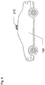
- Figure 6 represents a vehicle 100 equipped with a 360° scanning unit 210, such as a laser light scanning unit (LIDAR) to take a continuous series of 3d point clouds during a journey.
- the vehicle 100 also comprises an electronic control unit, a display unit and an autonomous driving unit.
- LIDAR laser light scanning unit
- the electronic control unit comprises a processing unit to process the obtained 3D point clouds, a classifying unit to classify an object of interest within processed 3D point clouds and a decision unit to decide to activate at least one of the display unit and the autonomous driving unit.
- the current classification method can reach similar level of performance on the test set proposed by Teichman et al. - that is to say 99.6% in pedestrian recognition accuracy.
- the advantage of the current method is that such a level of recognition is reached through a single shot (need only one Lidar frame). It does not need any additional algorithm such as tracking used in Teichman et al. which means that the response time is much faster.
- the current method can reply within the next 100ms whereas Teichman et al. may take more than 1s.
- the long response time of Teichman et al. is of course limiting for automated driving and collision avoidance purposes.
Landscapes
- Engineering & Computer Science (AREA)
- Physics & Mathematics (AREA)
- General Physics & Mathematics (AREA)
- Theoretical Computer Science (AREA)
- Multimedia (AREA)
- Remote Sensing (AREA)
- Radar, Positioning & Navigation (AREA)
- Computer Networks & Wireless Communication (AREA)
- Evolutionary Computation (AREA)
- Computer Vision & Pattern Recognition (AREA)
- Artificial Intelligence (AREA)
- Electromagnetism (AREA)
- Medical Informatics (AREA)
- Health & Medical Sciences (AREA)
- Data Mining & Analysis (AREA)
- General Health & Medical Sciences (AREA)
- Databases & Information Systems (AREA)
- Computing Systems (AREA)
- Software Systems (AREA)
- Bioinformatics & Cheminformatics (AREA)
- Life Sciences & Earth Sciences (AREA)
- Bioinformatics & Computational Biology (AREA)
- Evolutionary Biology (AREA)
- General Engineering & Computer Science (AREA)
- Optics & Photonics (AREA)
- Optical Radar Systems And Details Thereof (AREA)
- Traffic Control Systems (AREA)
- Image Analysis (AREA)
- Business, Economics & Management (AREA)
- Game Theory and Decision Science (AREA)
- Aviation & Aerospace Engineering (AREA)
- Automation & Control Theory (AREA)
Description
- The present invention relates to automated driving of vehicles. In particular, the present invention relates to a processing method of a three-dimensional (3D) point cloud derived using a Lidar or the like. It further relates to a method for classification of an object of interest within a 3D point cloud based on such processing method and using machine learning.
- These methods are useful especially in the field of human-assisted or autonomous vehicles using a depth sensor such as a Lidar sensor for obstacle detection and avoidance to navigate safely through environments. A Lidar sensor measures distance by illuminating a target with a laser light.
- Publication "Convolutional-Recursive Deep learning for 3D object classification", Richard Socher, Brody Huval, Bharath Bhat, Christopher D. Manning, Andrew Y. Ng, NIPS 2012, describes a method for 3D object classification using convolution-recursive deep learning. Input to the classification system needs RGB-D information, which is composed of RGB (red, green, blue) data from camera and D (distance) from depth sensor (STEREO, TOF, LIDAR, etc.). Such method presents several drawbacks among which the use of several sensors, namely a camera and a depth sensor, and the need of integrating together data from the camera (image) with the depth sensor (coordinates) for feeding the deep learning.
- Publication "Towards 3D object recognition via classification of arbitrary object tracks", Alex Teichman, Jesse Levinson, and Sebastian Thrun (ICRA 2011), describes a method of object recognition. In the described method, each source of data is used to compute hand-crafted features in sequential manner, followed by machine learning classification in series of cascades. This processing flow is optimized to solve mostly generic highly repetitive cases, but which reveals to have poor performance in less generic situations due to limited flexibility in parameter tuning that cannot be optimal for all situations at the same time. Finally, only intensity data is presented in form of 2D image maps, which limits parallel access and processing to single source of information.
-
Document EP 2 958 049 A2 describes a method of extracting feature regions from point cloud. The described method uses hand-crafted process for key point selection and descriptor computation for corresponding voxel, which is later classified by machine learning algorithm. Such processing pipeline, where features are pre-selected, could not let Deep Neural Network (DNN) to realize its potential in automatically finding features since significant part of the information was pre-filtered due to the choice of hand-crafted methods. Such pre-filtering could be beneficial for certain types of situations, while penalizing in many other real world situations. Further the described method does not compensate for low density of point cloud data, therefore having lower recognition accuracy for objects at far distance. - Publication "Obstacle Classification and 3D Measurement in Unstructured Environments Based on ToF Cameras" by Yu et al., describes an obstacle detection and classification method based on the use of Time-of-Flight (ToF) cameras for robotic navigation in unstructured environments. While using different kind of sensors (TOF vs. Lidar), intensity measurement is performed using a SR-3000 sensor controlled as a so-called 1-tap sensor. This means that in order to obtain reliable distance information, four consecutive exposures have to be performed. Fast moving targets in the scene may therefore cause errors in the distance calculation. According to the system parameters defined in the manual of the SR-3000 sensor (https://aiweb.techfak.uni-bielefeld.de/files/SR3000 manual V1.03.pdf), the described method uses intensity up to 7.5 m at 850nm wavelength. Further, the described method is based on a feature engineering approach, where all features are handcrafted so that the way how data is combined remained unchangeable independently of training data. It never uses combination of intensity and 3D information to form features for object recognition, but uses instead either 3D data or either 2D data processing consequently, while by having direct correspondence between intensity value and 3D measurement for each pixel. Furthermore, the described method uses intensity to filter noise during segmentation of regions of interest to improve 3D obstacle clustering. More particularly, the described method uses 4 separate channels I, X, Y, Z, which forms several spaces and cannot be processed easily and efficiently by convolution deep neural networks without additional processing stage.
- These prior arts address the problem of object classification by combination of data from multiple sensors and/or hand-crafted processes of feature selection, which gives acceptable results in common everyday situations. However, combination of sensors practically limits the conditions of use to situations where all used sensors could efficiently capture signal (e.g. day, good weather conditions, etc.) and fail to deliver accurate results in situations where one of the sensors cannot resolve the captured signal (e.g. camera at night, rainy conditions, etc.). Further, hand-crafted feature selection process could only be tuned to achieve maximum performance to very few typical situations (e.g. most common ones), while in others (rare/unique) cases it cannot achieve the same performance due to absence of hand-crafted features needed for robust classification. Another classification method is described in "Detection, segmentation and classification of 3D urban objects using mathematical morphology and supervised learning", Andrés Serna, Beatriz Marcotegui, ISPRS Journal of Photogrammetry and Remote Sensing, 01-07-2014, Elsevier, Amsterdam, NL.
- The present invention aims to address the above mentioned drawbacks of the prior art, and to propose first a processing method of a 3D point cloud which is simple and adapted for machine learning purposes and a method of classification of an object of interest within a 3D point cloud based on such processing method and using machine learning.
- In this aim, a first aspect of the invention is a processing method of a three-dimensional (3D) point cloud, comprising the steps of:
- obtaining a 3D point cloud from a predetermined view point of a depth sensor;
- extracting 3D coordinates (xyz) and intensity (i) data from each point of the 3D point cloud with respect to the view point;
- transforming the extracted 3D coordinates (xyz) and intensity (i) data into at least three two-dimensional (2D) spaces:
- ∘ an
intensity 2D space (IS) defined as a function of the intensity (i) data of each point; - ∘ a
height 2D space (HS) defined as a function of an elevation (h) data of each point, and - ∘ a
distance 2D space (DS) defined as a function of a distance (d) data between each point of 3D point cloud and the view point, defining a single multi-channel 2D space (IS, HS, DS).
- ∘ an
- The processing method according to the above embodiment of the invention provides a simple and easy way to transform the obtained 3D point cloud data into a single multi-channel 2D space defined by at least three 2D spaces including information on the intensity, the elevation and distance which allows to keep all essential information in order to recognize any object of interest within the 3D point cloud. Further, having an intensity space from the depth sensor intensity data, brings additional source of information useful to classify objects made from different materials. Furthermore, such single multi-channel 2D space is well adapted to machine learning algorithm and only needs to use a single depth sensor which is at lower cost compared to fusion of sensors and produces (time series of point clouds with 3D coordinates and intensity data with the same signal/noise ratio for all day/night and weather conditions. Thus by defining a single multi-channel 2D space (IS, HS, DS) corresponding to a single combined image space, it greatly increases ability of deep or convolutional neural network (DNN or CNN) to automatically determine the best combination of filters/features along of a depth column of 3 types of information (intensity, height, depth) for all layers simultaneously.
- Advantageously, the transforming step further includes the steps of detecting background points and setting a predetermined default value for detected background points. Background points which are detected thanks to their coordinates and intensity values, are set to a fixed value (e.g. 0, 0, 0) within the different 2D spaces. Therefore, foreground points (non-background) which are also transformed into 2D spaces would then not occupy them entirely. Indeed in the resulting 2D spaces, background points would be empty. Preferably the chosen default value should be different from values of points projected into 2D spaces for each space/channel. We experimented with different values and find out that the fixed default value (0,0,0) provides highest resulting accuracy. Furthermore, machine learning would then be able to use background/foreground information to learn outside shape or contours of objects of interest.
- Advantageously, the processing method includes a training phase during which it further comprises before the transforming step, the steps of:
- supplying tags data (Label-A) classifying objects in 1:N classes; and
- labelling each extracted point data (xyzi) as belonging to objects of 1 :N classes according to the supplied tags data (Label-A).
- Such labelling step ensures that during the training phase, objects of interest within the 3D point cloud are correctly assigned to the corresponding tags. It also shortens such training phase and increases reliability of classification during online phase.
- Advantageously, the transforming step includes a normalizing step of at least one of the 2D spaces, which consists in:
- normalizing the
intensity 2D space (IS) by applying an intensity normalizing function depending on the distance data to the intensity data of each point; and/or - normalizing the
height 2D space (HS) by applying a height normalizing function depending on the minimum and maximum elevation data within the 3D point cloud to the elevation data of each point; and/or - normalizing the
distance 2D space (DS) by applying a distance normalizing function depending on the minimum and maximum distance data within the 3D point cloud to the distance data of each point,
defining a normalized single multi-channel 2D space (ISN, HSN, DSN). - Such normalization renders uniform the data and enhances machine learning focus on finding generic patterns. Indeed, having a normalizing step by mixing absolute (unique) and relative (generic) data channels together has proven to be a validated trade-off between unique and generic cases within the 3D point cloud.
- Advantageously, the 3D point cloud is derived using a depth sensor such as a Lidar. Using a single depth sensor such as a Lidar to define the single multi-channel 2D space proves to be more economical and easy to integrate in particular as regards the produced data format.
- Advantageously, each of the
intensity 2D space, theheight 2D space and thedistance 2D space is respectively assigned to one of RGB (red, green, blue) value spaces for each point. Using the RGB value spaces to assign instead the intensity, height and distance spaces defining the single multi-channel 2D space allows a perfect data match with machine learning algorithm already designed to receive such RGB value spaces without needing any format modification. Thus, RGB value spaces are designed to be directly compatible with RGB image processing chain usually provided at the entry of machine learning algorithm. - According to another aim, a second aspect of the invention is a method for classification of an object of interest within a 3D point cloud, comprising the steps of:
- the processing method according to any of the first aspect method variants;
- supplying at least one single multi-channel 2D space (IS, HS, DS; ISN, HSN, DSN) to a machine learning such a deep neural network;
- outputting at least one classification label for each single multi-channel 2D space supplied identifying at least one object of interest within the 3D point cloud.
- The classification method according to the above embodiment of the invention provides a method that merges at least three different sources of information, namely intensity, height and distance together in the form of merged (normalized) 2D spaces defining a (normalized) single multi-channel 2D space which is a very efficient way to communicate this information for any machine learning. Indeed, single multi-channel 2D space can be used as entry for parallel processing chain of machine learning such as convolution or deep neural networks. With parallel access and processing of such merged 2D spaces, i.e. (normalized) single multi-channel 2D space, by the machine learning, it could automatically construct feature/decision space, which maximizes classification performance in much wider set of situations due to its ability to find more stable patterns, especially related to combination of intensity, height and distance information which is hard to be hand-crafted by humans. Therefore by designing a single multi-channel space, it extends depth of the input layer by a factor of 3, giving ability of CNN/DNN to learn the best combination of filters/features. It also speeds up reaction time which is important both during the training phase in order to be able to digest as much as possible data and also during the online phase (e.g. in driving conditions) in order to be able to recognize any potential danger as quickly as possible.
- Advantageously during a training phase of the machine learning, the supplying step consists in:
- accumulating a batch of multi-channel 2D spaces by repeating the processing method according to any of the first aspect method variants; and one or more of the following variants:
- supplying an average combination of a random number of multi-channel 2D spaces among said batch of accumulated multi-channel 2D spaces;
- supplying several multi-channel 2D spaces distributed in a predefined order among said batch of accumulated multi-channel 2D spaces;
- supplying a matrix of at least 2x2 multi-channel 2D spaces randomly selected among said batch of accumulated multi-channel 2D spaces.
- Such supplying variants using time series of data (accumulated batch) combined into one or several multi-channel 2D spaces is useful during the training stage in particular to compensate for low density of data at far distances and therefore allowing DNN to access more information and select more robust features/patterns resulting in a higher recognition accuracy for objects at far distance compared to prior art methods which does not compensate for low density of point cloud data.
- While it is also possible to supply the DNN with such combination of multi-channel 2D spaces during online stage, it is preferable to supply only a single multi-channel 2D space to get faster processing and output. Furthermore, a trained DNN benefits from the training phase to be able to accurately recognize stable patterns even if it receives low density of point data.
- According to another aim, the present invention further relates to a vehicle comprising:
- a depth sensor arranged to obtain 3D point clouds of a followed path when the vehicle is driven at least from a driver's point of view,
- a processing unit to process the obtained 3D point clouds according to the first aspect of the invention;
- a classifying unit to classify an object of interest within processed 3D point clouds according to the second aspect of the invention;
- a display unit arranged to display an information related to the classified object of interest;
- an autonomous driving unit arranged to control the vehicle depending on the classified object of interest; and
- a decision unit to decide to activate at least one of the display unit and the autonomous driving unit.
- Other features and advantages of the present invention will appear more clearly from the following detailed description of particular non-limitative examples of the invention, illustrated by the appended drawings where:
-
Figure 1 represents a processing method of a 3D point cloud according a preferred embodiment of the invention; -
Figure 2 represents a method for classification of an object of interest within a 3D point cloud according to the second aspect of the invention; -
Figures 3A-3D represents four variants of multi-channel 2D spaces; -
Figure 4 represents a vehicle equipped with the necessary units to implement the methods according to the invention. - The methods according to the present invention are according to a first aspect a processing method to transform a three-dimensional (3D) point cloud obtained by a depth sensor (e.g. Lidar) into one single or several multi-channel 2D spaces and according to a second aspect a method for classification of an object of interest within a 3D point cloud using machine learning (e.g. deep neural network) supplied by one or more multi-channel 2D spaces obtained by the processing method. This method of classification comprises a learning phase during which a deep neural network (DNN) learns all possible useful patterns to classify and recognize object of interest within a 3D point cloud based on as much as possible data supplied in the format of multi-channel 2D spaces and an online phase during which the DNN classifies object of interests recognized within 3D point cloud data supplied in the form of a single multi-channel 2D spaces.
- As already mentioned, these methods are useful especially in the field of human-assisted or autonomous vehicles using a depth sensor such as a Lidar sensor for obstacle detection and avoidance to navigate safely through environments. 3D point cloud outputs from the Lidar sensor provides the necessary data for a robot software including both of these methods to promptly and accurately determine where potential obstacles exist in the environment.
- According to a preferred processing method of a 3D point cloud illustrated on
figure 1 , the processing method comprises four stages A to D. Stage A is an acquisition stage of 3D point cloud data using a depth sensor such as a Lidar. Stage B is a projection stage also called transformation stage where 3D point cloud data are projected or transformed into several 2D spaces. Stage C is an optional stage where the 2D spaces obtained at stage B are normalized to get uniform data. Depending on whether the processing method is used during a training phase or online phase in relation with the classification method, stage D defines and combines several kinds of multi-channel 2D spaces to be further supplied to a machine learning. - In Stage A, the depth sensor used is preferably a Lidar sensor of the scanning laser range finder kind.
- This Lidar sensor scans its environment with a laser beam and measures for each point scanned its distance from the Lidar sensor view point as well as its intensity, allowing the reconstruction of a three-dimensional model of the scene in the form of a 3D point cloud (Data-A) at time T comprising 3D coordinates (xyz) and intensity data (i) for each point of the cloud with respect to the view point of the Lidar sensor.
- An example of Lidar sensor that can be used is the Velodyne lidar sensor HDL-64E (http://velodvnelidar.com/docs/datasheet/63-9194 Rev-D HDL-64E Data%20Sheet Web.pdf). This Lidar sensor uses 64 fixed-mounted lasers to measure the surrounding environment, each mechanically mounted to a specific vertical angle, with the entire unit spinning. This approach dramatically increases reliability, field of view (FOV), and point cloud density. The capture frequency of 3D point cloud is preferably between 10 and 15 Hz allowing to capture point cloud time series up to 120m at 905nm wavelenght.
- Preferably, during training phases, tags data (Label-A) classifying objects in 1:N classes is supplied so that obtained 3D point cloud data (Data-A) are tagged as belonging to objects of 1:N classes based on supplied tags data (Label-A).
- Stage A output corresponds to tagged point could data (Data-A and Label-A) being decomposed into 3D coordinates relative to the view point and intensity value for each point.
- In Stage B, (tagged) 3D point cloud data (Data-A) is inputted. At a time T, 3D coordinates (xyz) and intensity (i) data are projected into three different 2D image spaces, namely an
intensity 2D space (IS), aheight 2D space (HS) and adistance 2D space (DS). - For transforming 3D coordinates into 2D spaces, several methods can be used such as a projection matrix 3D to 2D defined to reproduced a 2D image corresponding to the view point of the Lidar sensor. For example, we can use a transformation matrix of the perspective projection type (https://en.wikipedia.org/wiki/Transformation matrix#Perspective projection). We can also use a transformation matrix by applying a 3D rotation (e.g. with respect to axis y) in order to obtain a canonical view or do rotation multiple times with different values of angle as a form of data augmentation before a projection on a 2D space so that the deep neural network would be more accurate recognizing novel views.
- The
intensity 2D space (IS) is defined as a function of the intensity (i) data of each point within the 3D point cloud. Such function can be very simple as for example a direct transposition of the intensity data into the 2D space or more complex depending also on the distance data. - The
height 2D space (HS) is defined herewith as a function of an elevation data (h) linked to the z coordinate of each point with respect to the view point. - The
distance 2D space (DS) is defined as a function of the distance (d) data between each point and the view point linked to the xyz coordinates. Such distance space aims to only reflect points from the point cloud that can be seen from the view point. One simple absolute function can be for example the following:
- Preferably background points, which are detected thanks to their distance and intensity values, are set to a fixed value (zero) within the different 2D spaces in order to be excluded from the machine learning.
- Stage B output corresponds to three 2D spaces including an intensity, height and
distance 2D spaces (Data-B) defining a single multi-channel 2D space. - In Stage C, the three 2D spaces (Data-B) are inputted. This stage is used to normalize all 2D spaces and renders uniform data. This normalization is done according to min and max values or any other adequate complex function, so that data represents relative changes of intensity, height and distance within point cloud at time T.
- The normalized
intensity 2D space (ISN) is obtained by applying an intensity normalizing function depending on the distance data to the intensity data of each point. An example of complex function is the normalization of intensity as function of the distance of the object as given in Velodyne user's manual and programming guide HDL-64E S3 "High Definition LiDAR Sensor" (see p. 45). http://velodvnelidar.com/docs/manuals/63-HDL64ES3g%20USERS%20MANUAL PROGRAM%20GUIDE,%20HDL-64E%20S3.pdf) - The normalized
height 2D space (HSN) is obtained by applying a height normalizing function depending on the minimum and maximum elevation data within the 3D point cloud to the elevation data of each point. An example of height normalizing function for each point of the point cloud can be as follows:
- The normalized
distance 2D space (DSN) is obtained by applying a distance normalizing function depending on the minimum and maximum distance data within the 3D point cloud to the distance data of each point. - An example of distance normalizing function for each point of the point cloud can be as follows:

- For complex functions of distance or height normalization, we can consider using the above mentioned formulas but with a weight [a, b] that depends on the distance between the view point (i.e. Lidar sensor) and the detected objects within the point cloud. We can set for example a weight close to [b] for far objects and close to [a] for closer objects where [a] > [b]. The values of [a] and [b] would preferably be defined experimentally to optimize the classification of objects at each target distance.


- Stage C output corresponds to normalized three 2D spaces (Data-C) defining a single normalized multi-channel 2D space.
- In Stage D, the normalized three 2D spaces (Data-C) are inputted. Depending on whether the processing method is used during a training phase or online phase, stage D defines and combines several kinds of (normalized) multi-channel 2D spaces (Data-D) to be further supplied to a machine learning as it will be explained in relation with
Figure 2 . Several examples of multi-channel 2D spaces will be presented in more details withFigures 3A-3D . -
Figures 3A-3D illustrate four examples of data combination outputted from Stage D to be supplied to the machine learning (Stage E,figure 2 ). Each figure shows an original time sequence of nine consecutive single multi-channel 2D spaces (ihd) corresponding to an accumulated batch of data inputted to Stage D (Data-C). Each 2D space is an array of 64x64 pixels, so that each single multi-channel 2D space (ihd) is an array of 64x64x3. - In the first example of
Figure 3A , Stage D output (Data-D) corresponds to the last single multi-channel 2D space (ihd 9). Such straight selection of the last single fixed position is preferably used during online phases when responsiveness from the machine learning is needed. Data-D format is the same as a single multi-channel 2D space, that is to say 64x64x3. - In the second example of
Figure 3B , Stage D output corresponds to an average combination of a random number of multi-channel 2D spaces among the original time sequence. Such average combination is preferably used during training phases of the machine learning in order to supply data based on more information (ihd 1-9). In the illustrated example, 6 out of 9 multi-channel 2D space are randomly selected (e.g. 2, 1, 5, 9, 6, 4). Data-D format is the same as a single multi-channel 2D space, that is to say 64x64x3. - In the third example of
Figure 3C , Stage D output corresponds to several multi-channel 2D spaces (ihd slices) distributed in a predefined order among the original time sequence. Such slice combination is also preferably used during training phases of the machine learning in order to supply more data (3 ihds) based on more information (ihd 1-9). In the illustrated example, first (ihd 1), medium (ihd 5) and last (ihd 9) multi-channel 2D space are selected. Data-D format is three times 64x64x3. - In the fourth example of
Figure 3D , Stage D output corresponds to a matrix of at least 2x2 multi-channel 2D spaces randomly selected among the original time sequence. Such matrix combination is also preferably used during training phases of the machine learning in order to supply more data (4 ihds) based on more information (ihd 1-9). In the illustrated example, four ihds (ihd - These last three examples provide the possibility to increase the data supplied to the deep neural network, without recording too many images upfront.
-
Figure 2 illustrates a preferred method for classification of an object of interest within a 3D point cloud based on the processing method presented in relation withFigure 1 . - Following stages A-D presented in
Figure 1 , Data-D is outputted to a machine learning, preferably a Deep Neural Network (DNN) at Stage E. The defined configuration of DNN could be one of several categories: network in network, convolutional, recurrent, etc. - Preferably, the used DNN can be a convolutional neural network, and more particularly, this convolutional neural network might be Inception V3, presented by Christian Szegedy, Vincent Vanhoucke, Sergey loffe, Jonathon Shlens, and Zbigniew Wojna at the following address: http://arxiv.orq/pdf/1512.00567v3.pdf. Such deep neural networks are well suited to analyse bi-dimensional objects such as multi-channel 2D spaces.
- In Stage E, any kind of Data-D presented in
Figure 3A-3D is inputted. During the training phase, Label-A data is also inputted. - A first step consists in connecting one or multiple multi-channel 2D spaces (Data-D) to one or multiple inputs of DNN's feature spaces (Conv-1, Conv-2, Conv-3), depending on its configuration and target performance level requirements. During training phases, most accurate combination will be preferably selected such as a time series of 2D spaces (e.g.
Figure 3C ) connected to multiple feature spaces, while during online phases a fast combination such as a single multi-channel 2D spaces (e.g.Figure 3A ) will be connected to unique feature space. Alternatively, it is possible to add a tracking algorithm, so that as long the object of interest is tracked, we can switch between any of the accumulation methods in order to get refined data combinations and more confident classification level. - A second step consists in training the DNN, where both feature and decision spaces shall be constructed via back-propagation of feedback generated by loss function (Loss-A) given forward signal from mini-batch of multi-channel 2D spaces with tags defined in Label-A (tags from each point cloud used to tag corresponding 2D spaces).
- A third step consists in propagating forward signal through DNN using online multi-channel 2D spaces (during online phases or combination of multi-channel 2D spaces (Data- during training spaces to get classification labels and estimated confidence level.
- Stage E output corresponds to classification labels preferably along with estimated confidence level for each point cloud or time series of point cloud acquired by the Lidar sensor.
- The goal achieved by such classification method is to automatically find best features and construct decision space that maximizes probability of correct classification of 3D point cloud time series data acquired by the Lidar sensor that can be used for example for 3D object recognition.
- Figure 6 represents a
vehicle 100 equipped with a 360°scanning unit 210, such as a laser light scanning unit (LIDAR) to take a continuous series of 3d point clouds during a journey. Thevehicle 100 also comprises an electronic control unit, a display unit and an autonomous driving unit. - The electronic control unit comprises a processing unit to process the obtained 3D point clouds, a classifying unit to classify an object of interest within processed 3D point clouds and a decision unit to decide to activate at least one of the display unit and the autonomous driving unit.
- For sake of comparison, the inventors did compare the current classification method with the results published in publication "Towards 3D object recognition via classification of arbitrary object tracks", of Alex Teichman, Jesse Levinson, and Sebastian Thrun (ICRA 2011).
- The current classification method can reach similar level of performance on the test set proposed by Teichman et al. - that is to say 99.6% in pedestrian recognition accuracy. The advantage of the current method is that such a level of recognition is reached through a single shot (need only one Lidar frame). It does not need any additional algorithm such as tracking used in Teichman et al. which means that the response time is much faster. As an example, when using a 100ms acquisition Lidar frame, the current method can reply within the next 100ms whereas Teichman et al. may take more than 1s. The long response time of Teichman et al. is of course limiting for automated driving and collision avoidance purposes.
- It will be understood that various modifications and/or improvements evident to those skilled in the art can be brought to the different embodiments of the invention described in the present description without departing from the scope of the invention defined by the accompanying claims.
Claims (11)
- A processing method of a three-dimensional (3D) point cloud, comprising the steps of:- obtaining a 3D point cloud from a predetermined view point of a depth sensor;- extracting 3D coordinates (xyz) and intensity (i) data from each point of the 3D point cloud with respect to the view point;- transforming the extracted 3D coordinates (xyz) and intensity (i) data into at least three two-dimensional (2D) spaces:o an intensity 2D space (IS) defined as a function of the intensity (i) data of each point;o a height 2D space (HS) defined as a function of an elevation (h) data of each point, ando a distance 2D space (DS) defined as a function of a distance (d) data between each point of 3D point cloud and the view point, defining a single multi-channel 2D space (IS, HS, DS).
- The processing method of claim 1, wherein the transforming step further includes:- detecting background points;- setting a predetermined default value for detected background points.
- The processing method of claim 1 or 2, including a training phase during which it further comprises before the transforming step, the steps of:- supplying tags data (Label-A) classifying objects in 1:N classes; and- labelling each extracted point data (xyzi) as belonging to objects of 1 :N classes according to the supplied tags data (Label-A).
- The processing method of any of claims 1 to 3, wherein the transforming step includes a normalizing step of at least one of the 2D spaces, which consists in:- normalizing the intensity 2D space (IS) by applying an intensity normalizing function depending on the distance data to the intensity data of each point; and/or- normalizing the height 2D space (HS) by applying a height normalizing function depending on the minimum and maximum elevation data within the 3D point cloud to the elevation data of each point; and/or- normalizing the distance 2D space (DS) by applying a distance normalizing function depending on the minimum and maximum distance data within the 3D point cloud to the distance data of each point,
defining a normalized single multi-channel 2D space (ISN, HSN, DSN). - The processing method of any of claims 1 to 4, wherein the 3D point cloud is derived using the depth sensor such as a Lidar.
- The processing method of any of claims 1 to 5, wherein each of the intensity 2D space, the height 2D space and the distance 2D space is respectively assigned to one of RGB value spaces for each point.
- A method for classification of an object of interest within a 3D point cloud, comprising the steps of:- the processing method according to any of claims 1 to 6;- supplying at least one single multi-channel 2D space (IS, HS, DS; ISN, HSN, DSN) to a machine learning such as a deep neural network;- outputting at least one classification label for each single multi-channel 2D space supplied identifying at least one object of interest within the 3D point cloud.
- The classification method of claim 7, wherein the machine learning comprises a training phase during which the supplying step consists in:- accumulating a batch of multi-channel 2D spaces by repeating the processing method according to any of claims 1 to 6;- supplying an average combination of a random number of multi-channel 2D spaces among said batch of accumulated multi-channel 2D spaces.
- The classification method of claim 7, wherein the machine learning comprises a training phase during which the supplying step consists in:- accumulating a batch of multi-channel 2D spaces by repeating the processing method according to any of claims 1 to 6;- supplying several multi-channel 2D spaces distributed in a predefined order among said batch of accumulated multi-channel 2D spaces.
- The classification method of claim 7, wherein the machine learning comprises a training phase during which the supplying step consists in:- accumulating a batch of multi-channel 2D spaces by repeating the processing method according to any of claims 1 to 6;- supplying a matrix of at least 2x2 multi-channel 2D spaces randomly selected among said batch of accumulated multi-channel 2D spaces.
- Vehicle comprising:- a depth sensor arranged to obtain 3D point clouds of a followed path when the vehicle is driven at least from a driver's point of view,- a processing unit to process the obtained 3D point clouds according to any of claims 1 to 6;- a classifying unit to classify an object of interest within processed 3D point clouds according to any of claims 7 to 10;- a display unit arranged to display an information related to the classified object of interest;- an autonomous driving unit arranged to control the vehicle depending on the classified object of interest; and- a decision unit to decide to activate at least one of the display unit and the autonomous driving unit.
Applications Claiming Priority (2)
| Application Number | Priority Date | Filing Date | Title |
|---|---|---|---|
| DE102016204177 | 2016-03-14 | ||
| PCT/EP2017/056039 WO2017157967A1 (en) | 2016-03-14 | 2017-03-14 | Processing method of a 3d point cloud |
Publications (2)
| Publication Number | Publication Date |
|---|---|
| EP3430427A1 EP3430427A1 (en) | 2019-01-23 |
| EP3430427B1 true EP3430427B1 (en) | 2021-07-21 |
Family
ID=58314212
Family Applications (1)
| Application Number | Title | Priority Date | Filing Date |
|---|---|---|---|
| EP17710902.2A Active EP3430427B1 (en) | 2016-03-14 | 2017-03-14 | Processing method of a 3d point cloud |
Country Status (5)
| Country | Link |
|---|---|
| US (1) | US10663594B2 (en) |
| EP (1) | EP3430427B1 (en) |
| JP (1) | JP6945785B2 (en) |
| CN (1) | CN108780154B (en) |
| WO (1) | WO2017157967A1 (en) |
Families Citing this family (78)
| Publication number | Priority date | Publication date | Assignee | Title |
|---|---|---|---|---|
| NL2016542B1 (en) * | 2016-04-04 | 2017-10-10 | Fugro N V | Spatial data analysis. |
| US10304335B2 (en) * | 2016-04-12 | 2019-05-28 | Ford Global Technologies, Llc | Detecting available parking spaces |
| US11067996B2 (en) | 2016-09-08 | 2021-07-20 | Siemens Industry Software Inc. | Event-driven region of interest management |
| US10802450B2 (en) | 2016-09-08 | 2020-10-13 | Mentor Graphics Corporation | Sensor event detection and fusion |
| CN106796728A (en) * | 2016-11-16 | 2017-05-31 | 深圳市大疆创新科技有限公司 | Method, device, computer system and mobile device for generating three-dimensional point cloud |
| US10509947B1 (en) * | 2017-04-11 | 2019-12-17 | Zoox, Inc. | Converting multi-dimensional data for image analysis |
| US10593042B1 (en) * | 2017-04-11 | 2020-03-17 | Zoox, Inc. | Perspective conversion for multi-dimensional data analysis |
| JP6689006B2 (en) * | 2017-08-25 | 2020-04-28 | ベイジン・ボイジャー・テクノロジー・カンパニー・リミテッド | Method and system for detecting environmental information of a vehicle |
| US20190079526A1 (en) * | 2017-09-08 | 2019-03-14 | Uber Technologies, Inc. | Orientation Determination in Object Detection and Tracking for Autonomous Vehicles |
| US10788831B2 (en) * | 2017-10-06 | 2020-09-29 | Wipro Limited | Method and device for identifying center of a path for navigation of autonomous vehicles |
| US11353589B2 (en) | 2017-11-17 | 2022-06-07 | Nvidia Corporation | Iterative closest point process based on lidar with integrated motion estimation for high definition maps |
| US10535138B2 (en) | 2017-11-21 | 2020-01-14 | Zoox, Inc. | Sensor data segmentation |
| CN108415035B (en) * | 2018-02-06 | 2019-08-02 | 北京三快在线科技有限公司 | A kind of processing method and processing device of laser point cloud data |
| US11157527B2 (en) * | 2018-02-20 | 2021-10-26 | Zoox, Inc. | Creating clean maps including semantic information |
| US11734910B2 (en) * | 2018-02-21 | 2023-08-22 | Robert Bosch Gmbh | Real-time object detection using depth sensors |
| US10798368B2 (en) * | 2018-03-13 | 2020-10-06 | Lyft, Inc. | Exposure coordination for multiple cameras |
| US10755112B2 (en) | 2018-03-13 | 2020-08-25 | Toyota Research Institute, Inc. | Systems and methods for reducing data storage in machine learning |
| US11618438B2 (en) | 2018-03-26 | 2023-04-04 | International Business Machines Corporation | Three-dimensional object localization for obstacle avoidance using one-shot convolutional neural network |
| WO2019216707A1 (en) * | 2018-05-10 | 2019-11-14 | Samsung Electronics Co., Ltd. | Method and apparatus for processing three dimensional object image using point cloud data |
| JP7152103B2 (en) * | 2018-06-01 | 2022-10-12 | Necソリューションイノベータ株式会社 | Estimation device, estimation method, and estimation program |
| CN110378905B (en) * | 2018-07-20 | 2022-07-05 | 北京京东尚科信息技术有限公司 | Neural network and method for extracting and matching angular points and equipment calibration method and device |
| KR102159320B1 (en) * | 2018-08-06 | 2020-09-23 | 국방과학연구소 | Object recognition method using 3d lidar |
| CN109271880B (en) * | 2018-08-27 | 2021-08-24 | 深圳一清创新科技有限公司 | Vehicle detection method, device, computer equipment and storage medium |
| RU2743895C2 (en) * | 2018-09-17 | 2021-03-01 | Общество с ограниченной ответственностью "Яндекс Беспилотные Технологии" | Methods and systems for computer to determine presence of objects |
| US11507052B2 (en) * | 2018-09-24 | 2022-11-22 | The Boeing Company | System and method of voxel based parametric specification for manufacturing a part |
| CN109061600B (en) * | 2018-09-28 | 2023-02-14 | 上海市刑事科学技术研究院 | A Target Recognition Method Based on Millimeter Wave Radar Data |
| CN111448478B (en) * | 2018-11-15 | 2023-02-28 | 北京嘀嘀无限科技发展有限公司 | System and method for correcting high-definition maps based on obstacle detection |
| EP3889646B1 (en) * | 2018-11-30 | 2025-06-25 | Koito Manufacturing Co., Ltd. | On-vehicle object identification system, automobile, vehicle lamp, classifier learning method, and arithmetic operation device |
| US11536844B2 (en) * | 2018-12-14 | 2022-12-27 | Beijing Voyager Technology Co., Ltd. | Dynamic sensor range detection for vehicle navigation |
| CN111352128B (en) * | 2018-12-21 | 2023-03-24 | 上海微功智能科技有限公司 | Multi-sensor fusion sensing method and system based on fusion point cloud |
| US11391574B2 (en) | 2019-01-18 | 2022-07-19 | Ford Global Technologies, Llc | Object detection |
| US10776651B2 (en) * | 2019-01-18 | 2020-09-15 | Intelligrated Headquarters, Llc | Material handling method, apparatus, and system for identification of a region-of-interest |
| KR102751272B1 (en) * | 2019-01-30 | 2025-01-10 | 현대자동차주식회사 | Apparatus for clustering of point cloud and method thereof |
| US10408939B1 (en) * | 2019-01-31 | 2019-09-10 | StradVision, Inc. | Learning method and learning device for integrating image acquired by camera and point-cloud map acquired by radar or LiDAR corresponding to image at each of convolution stages in neural network and testing method and testing device using the same |
| US10839543B2 (en) * | 2019-02-26 | 2020-11-17 | Baidu Usa Llc | Systems and methods for depth estimation using convolutional spatial propagation networks |
| WO2020206639A1 (en) * | 2019-04-10 | 2020-10-15 | 深圳市大疆创新科技有限公司 | Target object fitting method, point cloud sensor and mobile platform |
| US11016496B2 (en) | 2019-04-10 | 2021-05-25 | Argo AI, LLC | Transferring synthetic LiDAR system data to real world domain for autonomous vehicle training applications |
| CN112115744B (en) * | 2019-06-20 | 2024-05-21 | 北京京东叁佰陆拾度电子商务有限公司 | Point cloud data processing method and device, computer storage medium and electronic equipment |
| US20210004613A1 (en) | 2019-07-02 | 2021-01-07 | DeepMap Inc. | Annotating high definition map data with semantic labels |
| US11287530B2 (en) * | 2019-09-05 | 2022-03-29 | ThorDrive Co., Ltd | Data processing system and method for fusion of multiple heterogeneous sensors |
| US11474252B2 (en) | 2019-10-21 | 2022-10-18 | Piper Networks, Inc. | Transit location systems and methods using lidar |
| CN111061779A (en) * | 2019-12-16 | 2020-04-24 | 延安大学 | Data processing method and device based on big data platform |
| US11709080B2 (en) * | 2019-12-26 | 2023-07-25 | Horiba Stec, Co., Ltd. | Flow rate estimation for mass flow controller |
| US11430150B2 (en) | 2020-01-03 | 2022-08-30 | Samsung Electronics Co., Ltd. | Method and apparatus for processing sparse points |
| CN111310811B (en) * | 2020-02-06 | 2021-01-15 | 东华理工大学 | A 3D point cloud classification method for large scenes based on optimal combination of multidimensional features |
| CN111273316B (en) * | 2020-02-18 | 2022-03-08 | 中国科学院合肥物质科学研究院 | Multi-laser radar multi-view object detection method based on profile expansion fusion |
| KR20220134033A (en) * | 2020-03-26 | 2022-10-05 | 바이두닷컴 타임즈 테크놀로지(베이징) 컴퍼니 리미티드 | Point cloud feature-based obstacle filtering system |
| CN111126363B (en) * | 2020-03-30 | 2020-06-26 | 江苏广宇科技产业发展有限公司 | Object recognition method and device for automatic driving vehicle |
| CN111507340B (en) * | 2020-04-16 | 2023-09-01 | 北京深测科技有限公司 | Target point cloud data extraction method based on three-dimensional point cloud data |
| CN111553410B (en) * | 2020-04-27 | 2022-10-28 | 哈尔滨工程大学 | Point cloud recognition method based on key point local surface feature histogram and spatial relationship |
| JP7448945B2 (en) * | 2020-05-22 | 2024-03-13 | 国立大学法人金沢大学 | 3D map generation method and 3D map generation device |
| CN111949032A (en) * | 2020-08-18 | 2020-11-17 | 中国科学技术大学 | 3D obstacle avoidance navigation system and method based on reinforcement learning |
| US12002227B1 (en) | 2020-08-26 | 2024-06-04 | Apple Inc. | Deep partial point cloud registration of objects |
| CN112740268B (en) * | 2020-11-23 | 2022-06-07 | 华为技术有限公司 | Target detection method and device |
| US11733369B2 (en) | 2021-02-11 | 2023-08-22 | Waymo Llc | Methods and systems for three dimensional object detection and localization |
| US12196859B2 (en) | 2021-02-25 | 2025-01-14 | Google Llc | Label transfer between data from multiple sensors |
| CN113011511B (en) * | 2021-03-29 | 2024-01-19 | 江苏思玛特科技有限公司 | Sample generation method based on deep learning multispectral LiDAR data classification |
| CN113287969B (en) * | 2021-04-12 | 2022-07-01 | 安克创新科技股份有限公司 | Method for judging type of cleaning surface, method for adjusting cleaning mode, and cleaning apparatus |
| KR102335369B1 (en) | 2021-06-11 | 2021-12-06 | 주식회사 알씨테크 | Machine learning based automatic routing method and apparatus for semiconductor equipment |
| KR102310604B1 (en) | 2021-06-17 | 2021-10-14 | 주식회사 인피닉 | Method for processing data collected by multiple sensors, and computer program recorded on record-medium for executing method therefor |
| KR102310605B1 (en) | 2021-06-17 | 2021-10-14 | 주식회사 인피닉 | Control method of multiple sensors for data collection, and computer program recorded on record-medium for executing method thereof |
| KR102310602B1 (en) | 2021-06-17 | 2021-10-14 | 주식회사 인피닉 | Method for correcting difference of multiple sensors, and computer program recorded on record-medium for executing method therefor |
| KR102310606B1 (en) | 2021-07-08 | 2021-10-14 | 주식회사 인피닉 | Method for correcting difference of multiple sensors, and computer program recorded on record-medium for executing method therefor |
| KR102310601B1 (en) * | 2021-07-08 | 2021-10-13 | 주식회사 인피닉 | Control method of multiple sensors for data collection, and computer program recorded on record-medium for executing method thereof |
| KR102310608B1 (en) * | 2021-07-08 | 2021-10-13 | 주식회사 인피닉 | Method for processing data of machine learning for automatic driving based on radar and lidar, and computer program recorded on record-medium for executing method therefor |
| CN115712107A (en) * | 2021-08-23 | 2023-02-24 | 上海禾赛科技有限公司 | Signal processing method and detection method for laser radar and laser radar |
| KR20230031038A (en) * | 2021-08-26 | 2023-03-07 | (주)서울로보틱스 | Method and sensing device for monitoring region of interest in three-dimensional space |
| KR102656646B1 (en) * | 2021-08-26 | 2024-04-12 | (주)서울로보틱스 | Method for detecting installation abnormality of sensing device and sensing device of performing the same |
| JP7718687B2 (en) * | 2021-09-01 | 2025-08-05 | 国立大学法人金沢大学 | 3D map generation method and 3D map generation device |
| CN113486871B (en) * | 2021-09-07 | 2021-11-16 | 中国人民解放军国防科技大学 | Local autonomous control method, device and device for unmanned vehicle based on depth map |
| KR102729020B1 (en) * | 2021-09-08 | 2024-11-13 | 한국과학기술원 | Method and system for building lane-level map by using 3D point cloud map |
| CN114445701B (en) * | 2021-12-15 | 2023-07-04 | 深圳市速腾聚创科技有限公司 | Early warning method and device for platform obstacle, medium and electronic equipment |
| US11919451B2 (en) * | 2022-02-28 | 2024-03-05 | Nissan North America, Inc. | Vehicle data display system |
| CN115170728B (en) * | 2022-06-07 | 2023-05-26 | 青海师范大学 | Similarity measurement method of three-dimensional point cloud model |
| CN115294128B (en) * | 2022-10-08 | 2022-12-02 | 四川大学 | A monocular three-dimensional imaging method and device for digestive endoscopy |
| US12579814B2 (en) | 2023-03-28 | 2026-03-17 | Dell Products L.P. | Computer vision-based energy usage management system |
| CN116541639B (en) * | 2023-07-05 | 2023-09-19 | 湖南联智科技股份有限公司 | Tunnel super-undermining rapid calculation method based on point cloud data |
| FR3155905B1 (en) * | 2023-11-24 | 2025-10-10 | Continental Autonomous Mobility Germany GmbH | Processing data acquired by a lidar sensor |
Family Cites Families (11)
| Publication number | Priority date | Publication date | Assignee | Title |
|---|---|---|---|---|
| CN1783143A (en) * | 2005-09-09 | 2006-06-07 | 天津大学 | First-phase treating algorithm for color three dimension dot clowd data |
| US8050863B2 (en) * | 2006-03-16 | 2011-11-01 | Gray & Company, Inc. | Navigation and control system for autonomous vehicles |
| US8442304B2 (en) * | 2008-12-29 | 2013-05-14 | Cognex Corporation | System and method for three-dimensional alignment of objects using machine vision |
| US20100208981A1 (en) * | 2009-02-13 | 2010-08-19 | Harris Corporation | Method for visualization of point cloud data based on scene content |
| US8290305B2 (en) * | 2009-02-13 | 2012-10-16 | Harris Corporation | Registration of 3D point cloud data to 2D electro-optical image data |
| US8340400B2 (en) * | 2009-05-06 | 2012-12-25 | Honeywell International Inc. | Systems and methods for extracting planar features, matching the planar features, and estimating motion from the planar features |
| JP5503578B2 (en) * | 2011-03-10 | 2014-05-28 | パナソニック株式会社 | Object detection apparatus and object detection method |
| DE102012004396A1 (en) * | 2012-03-03 | 2013-09-05 | Volkswagen Aktiengesellschaft | Method and device for detecting objects in an environment of a vehicle |
| US9098754B1 (en) * | 2014-04-25 | 2015-08-04 | Google Inc. | Methods and systems for object detection using laser point clouds |
| KR102238693B1 (en) * | 2014-06-20 | 2021-04-09 | 삼성전자주식회사 | Method and apparatus for extracting feature regions in point cloud |
| CN104732588B (en) * | 2015-03-30 | 2016-06-01 | 中国测绘科学研究院 | A kind of power line three-dimensional rebuilding method based on airborne laser radar point cloud |
-
2017
- 2017-03-14 WO PCT/EP2017/056039 patent/WO2017157967A1/en not_active Ceased
- 2017-03-14 CN CN201780017140.1A patent/CN108780154B/en not_active Expired - Fee Related
- 2017-03-14 JP JP2018548732A patent/JP6945785B2/en active Active
- 2017-03-14 EP EP17710902.2A patent/EP3430427B1/en active Active
- 2017-03-14 US US16/085,341 patent/US10663594B2/en active Active
Also Published As
| Publication number | Publication date |
|---|---|
| EP3430427A1 (en) | 2019-01-23 |
| WO2017157967A1 (en) | 2017-09-21 |
| US10663594B2 (en) | 2020-05-26 |
| JP2019512802A (en) | 2019-05-16 |
| CN108780154B (en) | 2023-06-09 |
| JP6945785B2 (en) | 2021-10-06 |
| CN108780154A (en) | 2018-11-09 |
| US20190086546A1 (en) | 2019-03-21 |
Similar Documents
| Publication | Publication Date | Title |
|---|---|---|
| US10663594B2 (en) | Processing method of a 3D point cloud | |
| Handmann et al. | An image processing system for driver assistance | |
| EP3430576B1 (en) | Method for classification of unique/rare cases by reinforcement learning in neural networks | |
| US8917904B2 (en) | Vehicle clear path detection | |
| US8634593B2 (en) | Pixel-based texture-less clear path detection | |
| US8452053B2 (en) | Pixel-based texture-rich clear path detection | |
| Lookingbill et al. | Reverse optical flow for self-supervised adaptive autonomous robot navigation | |
| CN116504053A (en) | sensor fusion | |
| CN101900562A (en) | Clear path detection using divide approach | |
| US20230177818A1 (en) | Automated point-cloud labelling for lidar systems | |
| EP3629237B1 (en) | Device and method to improve the robustness against 'adversarial examples' | |
| JP7151676B2 (en) | Object recognition device and object recognition program | |
| EP3764124A1 (en) | Distance measuring apparatus, method for measuring distance, on-vehicle apparatus, and mobile object | |
| EP3845926B1 (en) | Multi-spectral lidar object tracking method and system | |
| CN109633686B (en) | Method and system for detecting ground obstacle based on laser radar | |
| CN113447940B (en) | Detection of distance measurement data | |
| US12354369B2 (en) | Method for automatically executing a vehicle function, method for evaluating a computer vision method and evaluation circuit for a vehicle | |
| Schamm et al. | Obstacle detection with a Photonic Mixing Device-camera in autonomous vehicles | |
| US20250085116A1 (en) | Identifying characteristics of a scene, with high level of safety integrity, by comparing sensor data with an expectation | |
| Park et al. | Robot navigation using camera by identifying arrow signs | |
| US20260105758A1 (en) | Leveraging llms for video analysis | |
| EP4738283A1 (en) | Mid-level ensemble for sensor fusion | |
| von Seelen et al. | Image processing of dynamic scenes | |
| WO2023046617A1 (en) | Road lane delimiter classification | |
| KR20240105000A (en) | Apparatus and method for recognizing object based on cylindrical grid map using LiDAR sensor data |
Legal Events
| Date | Code | Title | Description |
|---|---|---|---|
| STAA | Information on the status of an ep patent application or granted ep patent |
Free format text: STATUS: UNKNOWN |
|
| STAA | Information on the status of an ep patent application or granted ep patent |
Free format text: STATUS: THE INTERNATIONAL PUBLICATION HAS BEEN MADE |
|
| PUAI | Public reference made under article 153(3) epc to a published international application that has entered the european phase |
Free format text: ORIGINAL CODE: 0009012 |
|
| STAA | Information on the status of an ep patent application or granted ep patent |
Free format text: STATUS: REQUEST FOR EXAMINATION WAS MADE |
|
| 17P | Request for examination filed |
Effective date: 20181001 |
|
| AK | Designated contracting states |
Kind code of ref document: A1 Designated state(s): AL AT BE BG CH CY CZ DE DK EE ES FI FR GB GR HR HU IE IS IT LI LT LU LV MC MK MT NL NO PL PT RO RS SE SI SK SM TR |
|
| AX | Request for extension of the european patent |
Extension state: BA ME |
|
| DAV | Request for validation of the european patent (deleted) | ||
| DAX | Request for extension of the european patent (deleted) | ||
| GRAP | Despatch of communication of intention to grant a patent |
Free format text: ORIGINAL CODE: EPIDOSNIGR1 |
|
| STAA | Information on the status of an ep patent application or granted ep patent |
Free format text: STATUS: GRANT OF PATENT IS INTENDED |
|
| INTG | Intention to grant announced |
Effective date: 20210219 |
|
| GRAS | Grant fee paid |
Free format text: ORIGINAL CODE: EPIDOSNIGR3 |
|
| GRAA | (expected) grant |
Free format text: ORIGINAL CODE: 0009210 |
|
| STAA | Information on the status of an ep patent application or granted ep patent |
Free format text: STATUS: THE PATENT HAS BEEN GRANTED |
|
| AK | Designated contracting states |
Kind code of ref document: B1 Designated state(s): AL AT BE BG CH CY CZ DE DK EE ES FI FR GB GR HR HU IE IS IT LI LT LU LV MC MK MT NL NO PL PT RO RS SE SI SK SM TR |
|
| REG | Reference to a national code |
Ref country code: GB Ref legal event code: FG4D |
|
| REG | Reference to a national code |
Ref country code: CH Ref legal event code: EP |
|
| REG | Reference to a national code |
Ref country code: DE Ref legal event code: R096 Ref document number: 602017042442 Country of ref document: DE |
|
| REG | Reference to a national code |
Ref country code: AT Ref legal event code: REF Ref document number: 1413076 Country of ref document: AT Kind code of ref document: T Effective date: 20210815 |
|
| REG | Reference to a national code |
Ref country code: IE Ref legal event code: FG4D |
|
| REG | Reference to a national code |
Ref country code: LT Ref legal event code: MG9D |
|
| REG | Reference to a national code |
Ref country code: NL Ref legal event code: MP Effective date: 20210721 |
|
| REG | Reference to a national code |
Ref country code: AT Ref legal event code: MK05 Ref document number: 1413076 Country of ref document: AT Kind code of ref document: T Effective date: 20210721 |
|
| PG25 | Lapsed in a contracting state [announced via postgrant information from national office to epo] |
Ref country code: HR Free format text: LAPSE BECAUSE OF FAILURE TO SUBMIT A TRANSLATION OF THE DESCRIPTION OR TO PAY THE FEE WITHIN THE PRESCRIBED TIME-LIMIT Effective date: 20210721 Ref country code: RS Free format text: LAPSE BECAUSE OF FAILURE TO SUBMIT A TRANSLATION OF THE DESCRIPTION OR TO PAY THE FEE WITHIN THE PRESCRIBED TIME-LIMIT Effective date: 20210721 Ref country code: SE Free format text: LAPSE BECAUSE OF FAILURE TO SUBMIT A TRANSLATION OF THE DESCRIPTION OR TO PAY THE FEE WITHIN THE PRESCRIBED TIME-LIMIT Effective date: 20210721 Ref country code: FI Free format text: LAPSE BECAUSE OF FAILURE TO SUBMIT A TRANSLATION OF THE DESCRIPTION OR TO PAY THE FEE WITHIN THE PRESCRIBED TIME-LIMIT Effective date: 20210721 Ref country code: ES Free format text: LAPSE BECAUSE OF FAILURE TO SUBMIT A TRANSLATION OF THE DESCRIPTION OR TO PAY THE FEE WITHIN THE PRESCRIBED TIME-LIMIT Effective date: 20210721 Ref country code: NL Free format text: LAPSE BECAUSE OF FAILURE TO SUBMIT A TRANSLATION OF THE DESCRIPTION OR TO PAY THE FEE WITHIN THE PRESCRIBED TIME-LIMIT Effective date: 20210721 Ref country code: PT Free format text: LAPSE BECAUSE OF FAILURE TO SUBMIT A TRANSLATION OF THE DESCRIPTION OR TO PAY THE FEE WITHIN THE PRESCRIBED TIME-LIMIT Effective date: 20211122 Ref country code: NO Free format text: LAPSE BECAUSE OF FAILURE TO SUBMIT A TRANSLATION OF THE DESCRIPTION OR TO PAY THE FEE WITHIN THE PRESCRIBED TIME-LIMIT Effective date: 20211021 Ref country code: LT Free format text: LAPSE BECAUSE OF FAILURE TO SUBMIT A TRANSLATION OF THE DESCRIPTION OR TO PAY THE FEE WITHIN THE PRESCRIBED TIME-LIMIT Effective date: 20210721 Ref country code: BG Free format text: LAPSE BECAUSE OF FAILURE TO SUBMIT A TRANSLATION OF THE DESCRIPTION OR TO PAY THE FEE WITHIN THE PRESCRIBED TIME-LIMIT Effective date: 20211021 Ref country code: AT Free format text: LAPSE BECAUSE OF FAILURE TO SUBMIT A TRANSLATION OF THE DESCRIPTION OR TO PAY THE FEE WITHIN THE PRESCRIBED TIME-LIMIT Effective date: 20210721 |
|
| PG25 | Lapsed in a contracting state [announced via postgrant information from national office to epo] |
Ref country code: PL Free format text: LAPSE BECAUSE OF FAILURE TO SUBMIT A TRANSLATION OF THE DESCRIPTION OR TO PAY THE FEE WITHIN THE PRESCRIBED TIME-LIMIT Effective date: 20210721 Ref country code: LV Free format text: LAPSE BECAUSE OF FAILURE TO SUBMIT A TRANSLATION OF THE DESCRIPTION OR TO PAY THE FEE WITHIN THE PRESCRIBED TIME-LIMIT Effective date: 20210721 Ref country code: GR Free format text: LAPSE BECAUSE OF FAILURE TO SUBMIT A TRANSLATION OF THE DESCRIPTION OR TO PAY THE FEE WITHIN THE PRESCRIBED TIME-LIMIT Effective date: 20211022 |
|
| REG | Reference to a national code |
Ref country code: DE Ref legal event code: R097 Ref document number: 602017042442 Country of ref document: DE |
|
| PG25 | Lapsed in a contracting state [announced via postgrant information from national office to epo] |
Ref country code: DK Free format text: LAPSE BECAUSE OF FAILURE TO SUBMIT A TRANSLATION OF THE DESCRIPTION OR TO PAY THE FEE WITHIN THE PRESCRIBED TIME-LIMIT Effective date: 20210721 |
|
| PLBE | No opposition filed within time limit |
Free format text: ORIGINAL CODE: 0009261 |
|
| STAA | Information on the status of an ep patent application or granted ep patent |
Free format text: STATUS: NO OPPOSITION FILED WITHIN TIME LIMIT |
|
| PG25 | Lapsed in a contracting state [announced via postgrant information from national office to epo] |
Ref country code: SM Free format text: LAPSE BECAUSE OF FAILURE TO SUBMIT A TRANSLATION OF THE DESCRIPTION OR TO PAY THE FEE WITHIN THE PRESCRIBED TIME-LIMIT Effective date: 20210721 Ref country code: SK Free format text: LAPSE BECAUSE OF FAILURE TO SUBMIT A TRANSLATION OF THE DESCRIPTION OR TO PAY THE FEE WITHIN THE PRESCRIBED TIME-LIMIT Effective date: 20210721 Ref country code: RO Free format text: LAPSE BECAUSE OF FAILURE TO SUBMIT A TRANSLATION OF THE DESCRIPTION OR TO PAY THE FEE WITHIN THE PRESCRIBED TIME-LIMIT Effective date: 20210721 Ref country code: EE Free format text: LAPSE BECAUSE OF FAILURE TO SUBMIT A TRANSLATION OF THE DESCRIPTION OR TO PAY THE FEE WITHIN THE PRESCRIBED TIME-LIMIT Effective date: 20210721 Ref country code: CZ Free format text: LAPSE BECAUSE OF FAILURE TO SUBMIT A TRANSLATION OF THE DESCRIPTION OR TO PAY THE FEE WITHIN THE PRESCRIBED TIME-LIMIT Effective date: 20210721 Ref country code: AL Free format text: LAPSE BECAUSE OF FAILURE TO SUBMIT A TRANSLATION OF THE DESCRIPTION OR TO PAY THE FEE WITHIN THE PRESCRIBED TIME-LIMIT Effective date: 20210721 |
|
| 26N | No opposition filed |
Effective date: 20220422 |
|
| PG25 | Lapsed in a contracting state [announced via postgrant information from national office to epo] |
Ref country code: IT Free format text: LAPSE BECAUSE OF FAILURE TO SUBMIT A TRANSLATION OF THE DESCRIPTION OR TO PAY THE FEE WITHIN THE PRESCRIBED TIME-LIMIT Effective date: 20210721 |
|
| PG25 | Lapsed in a contracting state [announced via postgrant information from national office to epo] |
Ref country code: MC Free format text: LAPSE BECAUSE OF FAILURE TO SUBMIT A TRANSLATION OF THE DESCRIPTION OR TO PAY THE FEE WITHIN THE PRESCRIBED TIME-LIMIT Effective date: 20210721 |
|
| REG | Reference to a national code |
Ref country code: CH Ref legal event code: PL |
|
| REG | Reference to a national code |
Ref country code: BE Ref legal event code: MM Effective date: 20220331 |
|
| PG25 | Lapsed in a contracting state [announced via postgrant information from national office to epo] |
Ref country code: LU Free format text: LAPSE BECAUSE OF NON-PAYMENT OF DUE FEES Effective date: 20220314 Ref country code: LI Free format text: LAPSE BECAUSE OF NON-PAYMENT OF DUE FEES Effective date: 20220331 Ref country code: IE Free format text: LAPSE BECAUSE OF NON-PAYMENT OF DUE FEES Effective date: 20220314 Ref country code: CH Free format text: LAPSE BECAUSE OF NON-PAYMENT OF DUE FEES Effective date: 20220331 |
|
| PG25 | Lapsed in a contracting state [announced via postgrant information from national office to epo] |
Ref country code: BE Free format text: LAPSE BECAUSE OF NON-PAYMENT OF DUE FEES Effective date: 20220331 |
|
| PG25 | Lapsed in a contracting state [announced via postgrant information from national office to epo] |
Ref country code: HU Free format text: LAPSE BECAUSE OF FAILURE TO SUBMIT A TRANSLATION OF THE DESCRIPTION OR TO PAY THE FEE WITHIN THE PRESCRIBED TIME-LIMIT; INVALID AB INITIO Effective date: 20170314 |
|
| PG25 | Lapsed in a contracting state [announced via postgrant information from national office to epo] |
Ref country code: MK Free format text: LAPSE BECAUSE OF FAILURE TO SUBMIT A TRANSLATION OF THE DESCRIPTION OR TO PAY THE FEE WITHIN THE PRESCRIBED TIME-LIMIT Effective date: 20210721 Ref country code: CY Free format text: LAPSE BECAUSE OF FAILURE TO SUBMIT A TRANSLATION OF THE DESCRIPTION OR TO PAY THE FEE WITHIN THE PRESCRIBED TIME-LIMIT Effective date: 20210721 |
|
| PGFP | Annual fee paid to national office [announced via postgrant information from national office to epo] |
Ref country code: DE Payment date: 20240321 Year of fee payment: 8 Ref country code: GB Payment date: 20240318 Year of fee payment: 8 |
|
| PGFP | Annual fee paid to national office [announced via postgrant information from national office to epo] |
Ref country code: FR Payment date: 20240320 Year of fee payment: 8 |
|
| PG25 | Lapsed in a contracting state [announced via postgrant information from national office to epo] |
Ref country code: TR Free format text: LAPSE BECAUSE OF FAILURE TO SUBMIT A TRANSLATION OF THE DESCRIPTION OR TO PAY THE FEE WITHIN THE PRESCRIBED TIME-LIMIT Effective date: 20210721 |
|
| PG25 | Lapsed in a contracting state [announced via postgrant information from national office to epo] |
Ref country code: MT Free format text: LAPSE BECAUSE OF FAILURE TO SUBMIT A TRANSLATION OF THE DESCRIPTION OR TO PAY THE FEE WITHIN THE PRESCRIBED TIME-LIMIT Effective date: 20210721 |
|
| REG | Reference to a national code |
Ref country code: DE Ref legal event code: R119 Ref document number: 602017042442 Country of ref document: DE |
|
| GBPC | Gb: european patent ceased through non-payment of renewal fee |
Effective date: 20250314 |
|
| PG25 | Lapsed in a contracting state [announced via postgrant information from national office to epo] |
Ref country code: DE Free format text: LAPSE BECAUSE OF NON-PAYMENT OF DUE FEES Effective date: 20251001 |
|
| PG25 | Lapsed in a contracting state [announced via postgrant information from national office to epo] |
Ref country code: GB Free format text: LAPSE BECAUSE OF NON-PAYMENT OF DUE FEES Effective date: 20250314 |
|
| PG25 | Lapsed in a contracting state [announced via postgrant information from national office to epo] |
Ref country code: FR Free format text: LAPSE BECAUSE OF NON-PAYMENT OF DUE FEES Effective date: 20250331 |