EP3430367B1 - Fugitive emission detection - Google Patents
Fugitive emission detection Download PDFInfo
- Publication number
- EP3430367B1 EP3430367B1 EP17713064.8A EP17713064A EP3430367B1 EP 3430367 B1 EP3430367 B1 EP 3430367B1 EP 17713064 A EP17713064 A EP 17713064A EP 3430367 B1 EP3430367 B1 EP 3430367B1
- Authority
- EP
- European Patent Office
- Prior art keywords
- valve
- cavity
- valve operator
- pressure
- operator
- Prior art date
- Legal status (The legal status is an assumption and is not a legal conclusion. Google has not performed a legal analysis and makes no representation as to the accuracy of the status listed.)
- Active
Links
- 238000001514 detection method Methods 0.000 title description 45
- 239000012530 fluid Substances 0.000 claims description 27
- 230000008859 change Effects 0.000 claims description 24
- 238000007789 sealing Methods 0.000 claims description 22
- 238000000034 method Methods 0.000 claims description 19
- 238000012544 monitoring process Methods 0.000 claims description 19
- 238000004891 communication Methods 0.000 claims description 4
- 238000013022 venting Methods 0.000 claims description 4
- 238000012545 processing Methods 0.000 claims description 3
- 239000000126 substance Substances 0.000 description 8
- 239000007789 gas Substances 0.000 description 7
- 230000003068 static effect Effects 0.000 description 5
- 238000007689 inspection Methods 0.000 description 4
- 238000012423 maintenance Methods 0.000 description 4
- 238000013459 approach Methods 0.000 description 3
- 238000011156 evaluation Methods 0.000 description 3
- 238000004519 manufacturing process Methods 0.000 description 3
- 230000008569 process Effects 0.000 description 3
- 230000008901 benefit Effects 0.000 description 2
- 238000009529 body temperature measurement Methods 0.000 description 2
- 238000011109 contamination Methods 0.000 description 2
- 238000011161 development Methods 0.000 description 2
- 230000018109 developmental process Effects 0.000 description 2
- 230000000694 effects Effects 0.000 description 2
- 230000010354 integration Effects 0.000 description 2
- 238000005259 measurement Methods 0.000 description 2
- 238000005065 mining Methods 0.000 description 2
- 238000012986 modification Methods 0.000 description 2
- 230000004048 modification Effects 0.000 description 2
- 230000002265 prevention Effects 0.000 description 2
- 230000035945 sensitivity Effects 0.000 description 2
- 239000007921 spray Substances 0.000 description 2
- 238000012360 testing method Methods 0.000 description 2
- 238000011144 upstream manufacturing Methods 0.000 description 2
- 239000010913 used oil Substances 0.000 description 2
- 239000002351 wastewater Substances 0.000 description 2
- XLYOFNOQVPJJNP-UHFFFAOYSA-N water Substances O XLYOFNOQVPJJNP-UHFFFAOYSA-N 0.000 description 2
- 230000009471 action Effects 0.000 description 1
- 239000012080 ambient air Substances 0.000 description 1
- 238000003339 best practice Methods 0.000 description 1
- 238000009530 blood pressure measurement Methods 0.000 description 1
- 230000015556 catabolic process Effects 0.000 description 1
- 238000006731 degradation reaction Methods 0.000 description 1
- 230000001419 dependent effect Effects 0.000 description 1
- 230000007613 environmental effect Effects 0.000 description 1
- 238000002955 isolation Methods 0.000 description 1
- 239000000463 material Substances 0.000 description 1
- 230000013011 mating Effects 0.000 description 1
- 238000012856 packing Methods 0.000 description 1
- 230000009467 reduction Effects 0.000 description 1
- 230000008439 repair process Effects 0.000 description 1
- 230000004044 response Effects 0.000 description 1
- 238000009420 retrofitting Methods 0.000 description 1
Images

Classifications
-
- G—PHYSICS
- G01—MEASURING; TESTING
- G01M—TESTING STATIC OR DYNAMIC BALANCE OF MACHINES OR STRUCTURES; TESTING OF STRUCTURES OR APPARATUS, NOT OTHERWISE PROVIDED FOR
- G01M3/00—Investigating fluid-tightness of structures
- G01M3/02—Investigating fluid-tightness of structures by using fluid or vacuum
- G01M3/26—Investigating fluid-tightness of structures by using fluid or vacuum by measuring rate of loss or gain of fluid, e.g. by pressure-responsive devices, by flow detectors
- G01M3/28—Investigating fluid-tightness of structures by using fluid or vacuum by measuring rate of loss or gain of fluid, e.g. by pressure-responsive devices, by flow detectors for pipes, cables or tubes; for pipe joints or seals; for valves ; for welds
- G01M3/2876—Investigating fluid-tightness of structures by using fluid or vacuum by measuring rate of loss or gain of fluid, e.g. by pressure-responsive devices, by flow detectors for pipes, cables or tubes; for pipe joints or seals; for valves ; for welds for valves
-
- F—MECHANICAL ENGINEERING; LIGHTING; HEATING; WEAPONS; BLASTING
- F16—ENGINEERING ELEMENTS AND UNITS; GENERAL MEASURES FOR PRODUCING AND MAINTAINING EFFECTIVE FUNCTIONING OF MACHINES OR INSTALLATIONS; THERMAL INSULATION IN GENERAL
- F16K—VALVES; TAPS; COCKS; ACTUATING-FLOATS; DEVICES FOR VENTING OR AERATING
- F16K37/00—Special means in or on valves or other cut-off apparatus for indicating or recording operation thereof, or for enabling an alarm to be given
- F16K37/0025—Electrical or magnetic means
- F16K37/005—Electrical or magnetic means for measuring fluid parameters
-
- F—MECHANICAL ENGINEERING; LIGHTING; HEATING; WEAPONS; BLASTING
- F16—ENGINEERING ELEMENTS AND UNITS; GENERAL MEASURES FOR PRODUCING AND MAINTAINING EFFECTIVE FUNCTIONING OF MACHINES OR INSTALLATIONS; THERMAL INSULATION IN GENERAL
- F16K—VALVES; TAPS; COCKS; ACTUATING-FLOATS; DEVICES FOR VENTING OR AERATING
- F16K37/00—Special means in or on valves or other cut-off apparatus for indicating or recording operation thereof, or for enabling an alarm to be given
- F16K37/0075—For recording or indicating the functioning of a valve in combination with test equipment
- F16K37/0083—For recording or indicating the functioning of a valve in combination with test equipment by measuring valve parameters
-
- G—PHYSICS
- G01—MEASURING; TESTING
- G01M—TESTING STATIC OR DYNAMIC BALANCE OF MACHINES OR STRUCTURES; TESTING OF STRUCTURES OR APPARATUS, NOT OTHERWISE PROVIDED FOR
- G01M3/00—Investigating fluid-tightness of structures
- G01M3/02—Investigating fluid-tightness of structures by using fluid or vacuum
- G01M3/04—Investigating fluid-tightness of structures by using fluid or vacuum by detecting the presence of fluid at the leakage point
- G01M3/16—Investigating fluid-tightness of structures by using fluid or vacuum by detecting the presence of fluid at the leakage point using electric detection means
- G01M3/18—Investigating fluid-tightness of structures by using fluid or vacuum by detecting the presence of fluid at the leakage point using electric detection means for pipes, cables or tubes; for pipe joints or seals; for valves; for welds; for containers, e.g. radiators
- G01M3/184—Investigating fluid-tightness of structures by using fluid or vacuum by detecting the presence of fluid at the leakage point using electric detection means for pipes, cables or tubes; for pipe joints or seals; for valves; for welds; for containers, e.g. radiators for valves
-
- G—PHYSICS
- G01—MEASURING; TESTING
- G01M—TESTING STATIC OR DYNAMIC BALANCE OF MACHINES OR STRUCTURES; TESTING OF STRUCTURES OR APPARATUS, NOT OTHERWISE PROVIDED FOR
- G01M3/00—Investigating fluid-tightness of structures
- G01M3/02—Investigating fluid-tightness of structures by using fluid or vacuum
- G01M3/26—Investigating fluid-tightness of structures by using fluid or vacuum by measuring rate of loss or gain of fluid, e.g. by pressure-responsive devices, by flow detectors
- G01M3/28—Investigating fluid-tightness of structures by using fluid or vacuum by measuring rate of loss or gain of fluid, e.g. by pressure-responsive devices, by flow detectors for pipes, cables or tubes; for pipe joints or seals; for valves ; for welds
- G01M3/2807—Investigating fluid-tightness of structures by using fluid or vacuum by measuring rate of loss or gain of fluid, e.g. by pressure-responsive devices, by flow detectors for pipes, cables or tubes; for pipe joints or seals; for valves ; for welds for pipes
- G01M3/2815—Investigating fluid-tightness of structures by using fluid or vacuum by measuring rate of loss or gain of fluid, e.g. by pressure-responsive devices, by flow detectors for pipes, cables or tubes; for pipe joints or seals; for valves ; for welds for pipes using pressure measurements
Definitions
- This invention relates to a method and apparatus for fugitive emission detection and in particularly, but not exclusively, to a fugitive emission detection arrangement for use industrial valves.
- Industrial valves are very widely used globally to control the flow of fluids in manufacturing, civil services and other industries.
- industrial valves may be used oil and gas, water and waste water, power, marine, mining, food, pharmaceutical and chemical industries.
- Industrial valves must be designed to minimise leakage. In particular as valves by their nature, necessitate some non-static seals they will present a potential leak location in any industrial flow system.
- Valve manufactures are constantly improving their products to reduce the risk but this cannot eliminate all risk of leakage. Such Leakage may lead to loss of profit/revenue, increased maintenance costs, increased process risk/risk to operators, risk of contamination (to the environment) and/or risk of contamination (to the fluid/product).
- the present invention is directly intended to address the second issue, namely the monitoring and detection of leaks. This is commonly referred to in the art as "fugitive emission detection”. It will, however, be appreciated that the third and fourth principles are directly impacted by the execution of the fugitive emission control and detection. As such, the skilled person would appreciate that an effective fugitive emission detection system could have a profound impact on the broader fugitive emission control processes.
- Some techniques rely upon manual, labour intensive, detection. For example: Audible Noise detection in which an operator/inspector listening for unusual noises from equipment; the use of Gas Leak Spray in which a suspected leak area is sprayed with a spray and resulting in visible gas bubbles when a leak is present; or traditional valve isolation and inspection in which the valve is isolated and manually inspected (possibly as part of a preventative maintenance programme).
- Audible Noise detection in which an operator/inspector listening for unusual noises from equipment
- Gas Leak Spray in which a suspected leak area is sprayed with a spray and resulting in visible gas bubbles when a leak is present
- traditional valve isolation and inspection in which the valve is isolated and manually inspected (possibly as part of a preventative maintenance programme).
- US Patent No. 6050296 describes a control apparatus.
- the control apparatus comprises an actuating drive and an actuator connected therewith, whereby the actuator comprises at least one valve face and a throttle element that works herewith.
- the throttle element can be moved relative to the valve face by means of an actuating spindle connected with the actuating drive for the execution of a rotational and/or piston motion.
- the actuating spindle is sealed against the valve interior chamber at a first sealing location.
- a second sealing location likewise seals the actuating spindle, and, between the two sealing locations.
- There is a test chamber that is accessible via at least one control terminal, to which chamber a pressure sensor is connected.
- the pressure sensor is connected with an evaluation unit for monitoring the operation of the control apparatus.
- the signal output of the pressure sensor can be compared, in the evaluation unit, with a response threshold dependent on at least one temperature signal, for the outputting of an error status message to an error status output of the evaluation unit.
- US Patent Publication No. 2015041000 describes a system to monitor performance of packing material in a seal.
- This document describes a system that can detect leaks that occur in seals, and in one example, to seals found in a valve.
- the system utilises sensors that measure fluid properties of a sample volume proximate to the seal.
- the system can compare data from these measurements with data from a sample of a reference fluid (e.g., ambient air) to indicate the presence of working fluid in the sample volume.
- a reference fluid e.g., ambient air
- US Patent No. 5203370 describes an apparatus for mounting a rotary actuator, having a rotary drive bushing, to a valve stem of a rotary controlled valve having first and second primary seals and a fugitive fluid collection chamber therebetween.
- the apparatus includes a mounting member disposed between the actuator and the valve, which is removably fastened thereto, to permit the valve stem to coaxially engage the rotary drive bushing provided in the rotary actuator.
- O-rings are affixed to flanges that extend from the ends of the mounting member for creating a fluid-tight seal between the mounting member and the actuator and between the mounting member and the valve.
- the fluid-tight mounting member serves to provide a secondary fugitive fluid collection chamber outboard of the secondary stem seals that is adapted to collect the fugitive fluid that passes the secondary stem seals.
- a fluid detection device may be attached to the secondary fugitive fluid collection chamber via a port provided in the mounting member.
- Gas Leak Detection Devices are available which may be handheld or worn by inspection personnel and measures the environment and emits an alarm upon sensing emissions. Inspections using such "sniffer" devices may be carried out at fixed intervals (with the intervals being determined based upon safety). Typically such devices are focused on the detection of dangerous levels of a volatile gas which could be harmful to the user.
- Infrared Temperature measurement tools measure and compare temperature values upstream and downstream of the valve.
- the Joule-Thomson effect states that both upstream and downstream temperatures must be equal; as such discrepancies between these values may be an indicator of fugitive emissions.
- not all leaks can be detected by this method (some leaks do not cause a measurable temperature differential).
- the external temperature readings of pipelines and fittings can be influenced by other external factors which may result in a loss of accuracy or even the ability to detect changes related to leaks altogether.
- a further detection system is Acoustic Emissions which utilises an indirect measure of turbulence within the valve (for example via a piezoelectric device) and can determine leakage based upon variations in the turbulence.
- Such systems only provide an indirect indication of leakage and require extensive tailoring to a particular valve. For example a large database of empirical data is needed to support the detection of changes and many variables in the detection need specific, detailed, knowledge of the particular valve and flow conditions.
- Ultrasonic Stethoscopes may be used to pass an ultrasonic wave through the valve to find possible leak paths.
- the efficiency of this method is currently unconfirmed.
- there are clear limitation/difficulties to this approach since listening frequency must be very carefully selected to filter out nearby noise. Accordingly, the use of Ultrasonic Stethoscopes requires a specifically trained and skilled operator.
- valve operator for a valve, the valve operator comprising:
- Also described herein is an industrial valve operator having an integrated valve fugitive emission detection arrangement.
- an integrated fugitive emissions detection arrangement comprises the detector being at least partially integrated into the valve operator but the detector may optionally be integrated into a control/monitoring network.
- a local processing unit may be provided with/at the valve operator.
- a remote processor for example a computer shared by a plurality of devices may be utilised with the processor receiving data over a network.
- the valve may be an industrial valve.
- embodiments of the invention may provide a valve operator having an integrated valve fugitive emission detection arrangement.
- valve operator may be any known type of valve operator device which, the skilled person will appreciate would ordinarily be attached to an industrial valve to engage the valve stem and provide a means for controlling and actuating the valve in use.
- valve operator may be a simple actuation lever or hand-wheel.
- the operator could be a valve actuator, for example the valve operator could be any of an electric, Pneumatic or Hydraulic actuator.
- the valve operator may also be an intermediate component in a valve actuation system, for example a gearbox or adaptor. Such intermediate components may be attached to an industrial valve (to engage the valve stem) and then in turn be connected to a valve actuator or the like.
- valve operators are readily commercially available from Rotork PLC group of companies.
- embodiments of the invention may be easily incorporated into such known devices with only relatively minimal modification.
- the invention is predicated, at least in part, on the Applicants' recognition that the static seals in the valve and/or valve operator are highly reliable (and can nominally be considered to be a perfect seal) whereas a rotating seal such as that provided at the valve stem is unavoidably less reliable (and, therefore, typically requires more regular maintenance and inspection).
- a rotating seal such as that provided at the valve stem is unavoidably less reliable (and, therefore, typically requires more regular maintenance and inspection).
- embodiments of the invention allow monitoring/detection to be carried out at the valve operator, rather than at the valve itself, which will almost always be in a more convenient and/or readily accessible location. Even though embodiments may allow the detection to be carried out at a more convenient location it is also an advantage that, unlike many prior art methods (such as Infrared Temperature or Acoustic Emissions), embodiments of the invention enable direct testing of leaking fluid.
- valve operators are generally easily replaced or upgraded (whereas the valve may be in a flow which needs continuous operation).
- valve operators may generally be configured for attachment onto standardised valve flanges.
- a valve operator in accordance with embodiments of the invention may readily be retrofitted to existing industrial valves.
- the at least one sensor may measure the temperature and pressure within the cavity.
- the at least one sensor may be provided internally to the valve operator.
- the at one least sensor may generally be direct in communication with the interior of the cavity.
- the pressure and temperature in a volume are related directly to the amount of substance present within the volume (as expressed in the ideal gas law).
- the volume of the cavity in the valve operator is known. Further, the volume is typically constant. Measurement of the pressure and temperature can be used to provide an indication of any change in the amount of substance within the cavity.
- any change detected in the cavity can be assumed to have escaped from the valve stem housing (i.e. having leaked past a valve stem seal).
- the detection of a change in the cavity may be used as a direct measure indicative of fugitive emissions from the valve.
- the sealing face of the valve operator may include at least one resilient sealing member, for example an O-ring.
- the resilient seal member may be compressed between opposing portions of the flange and sealing face in use to provide an effective seal.
- a fugitive emissions detection arrangement in accordance with some embodiments of the invention may only be required to detect a change in the amount (generally an increase) of substance in the chamber (to detect a leak) rather than determine the actual quantity of any such change. This may simplify the implementation of the embodiment since, if the volume of the cavity is constant, it is not necessary to know or measure the actual cavity volume. This may for example, advantageously eliminate any errors or calibration required due to tolerances in manufacturing.
- the cavity may be provided with an overpressure vent outlet.
- the vent outlet may ensure that the fluid pressure within the cavity cannot exceed a predetermined nominal safe pressure value. If the pressure exceeds the nominal safe pressure value the overpressure vent outlet will allow fluid from the cavity to be vented to the external atmosphere.
- the predetermined nominal safe pressure may be selected to be sufficiently low to ensure that damage will not occur to the valve operator.
- the predetermined nominal safe pressure value may be selected to be in excess of the sensitivity of the fugitive emissions detection. As such, in normal operation any fugitive emissions would be expected to be detected by the system in advance of the need for the system to vent (and action may be possible to prevent the emissions prior to the pressure in the housing reaching the nominal safe pressure).
- the overpressure vent outlet may for example comprise a valve or burst diaphragm to allow venting when the selected nominal safe pressure is reached or exceeded.
- the valve operator may further comprise a processor for receiving data from the at least one sensor and for determining whether they are indicative of fugitive emissions.
- the processor may be local to the valve operator or could be remotely located (for example as part of a networked system). Locating the processor locally may advantageously allow the system to provide a local indication of the detection of fugitive emissions (for example in addition to sending a signal to a monitoring or control system such that redundancy is provided).
- the processor may for example be arranged to receive pressure and temperature measurements relating to the cavity from the at least one sensor and determine whether any change in substance within the cavity has occurred.
- the values of P 0 and T 0 may be recorded by the processor when the device is re-set.
- a re-set button or function may be provided which causes the process to record sense values as the datum value for both pressure and temperature.
- the valve operator may be provided with a network module (for example a receiver/transmitter connected to a processor). This may for example allow integration of the fugitive emissions detection into a control or monitoring network.
- the network transmitter could for example be configured to be connected into a conventional wired or wireless field network.
- the network transmitter could be arranged to be compatible with the Pakscan system available from Rotork.
- Providing networked fugitive emissions detection arrangements may advantageously allow for live and continuous monitoring. Further, the system may reduce fugitive emissions to the environment by providing prompt notification or flagging of any valve errors.
- the valve operator in embodiments of the invention may include additional sensor devices for detecting the operational status of the valve and/or valve operator.
- a position indicator could be provided to determine the stroke position of the valve.
- This information may be integrated with the monitored data from the position sensors (for example in the processor). This may enable the data from the fugitive emissions detection to be utilised for additional diagnostic purposes.
- a monitoring or control system may be able to utilise the position sensor information along with fugitive emissions detection to correlate the stage/position of the valve operation at which emissions are occurring.
- the valve operator housing defining the housing may at least partially house the components of the valve operator.
- it may be a cast housing.
- the housing may for example be a housing meeting a required environmental sealing standard.
- valve operator and valve could be integrally formed without altering the underlying principle of the integration of the fugitive emissions detection into the valve operator portion of the valve assembly.
- a fugitive emissions detection arrangement for a valve comprising:
- the method may be a method of retrofitting. Accordingly, the step of providing a valve operator may comprise the additional step of removing an existing valve operator.
- valve operator is a valve operator in accordance with any embodiment of the invention.
- the method may further comprise connecting the valve operator to a control network.
- the step of monitoring the fluid conditions may comprise monitoring changes in pressure and/or temperature within a portion of the valve operator to provide an indication of any fugitive emissions.
- FIG. 1 shows a typical industrial valve assembly 10 which may be used to control the flow of fluids in industrial applications.
- the valve assembly 10 could be used oil and gas, water and waste water, power, marine, mining, food, pharmaceutical and chemical industries.
- the valve assembly comprises a valve 10 including a valve member 12, connected to a valve actuation stem 14.
- the valve could for example be a quarter turn valve or a multi-turn valve arrangement.
- the valve member 12 and stem 14 are provided within a housing 16.
- the upper portion of the housing 16 comprises a valve stem passage 17 and terminates at a flange 18.
- At least one stem seal 15 is provided between the stem passage 17 and stem 14 and is intended to prevent the escape of fluid from the valve housing 16 in use.
- the stem seal 15 is a non-static seal (as the stem 14 will generally rotate relative to the passage 17 during actuation) it provides a less reliable seal than static seals (for example those between the valve housing and the associated pipe or conduit.
- static seals for example those between the valve housing and the associated pipe or conduit.
- the valve assembly 1 also includes a valve operator 20.
- the valve operator 20 drivingly engages an upper drive portion of the valve stem 14 and provides a means for controlling and actuating the valve member 12 in use.
- the valve operator 20 is provided within a valve operator housing 22 which is arranged to be connected to the valve housing 16 via the flange 18.
- the valve operator could be a manual operator such as a hand-wheel (which may include an associated gearing arrangement).
- the valve operator represents an electrical valve actuator (for example one of the IQ actuator range available form Rotork Controls Limited).
- valve operator may also be an intermediate component in a valve actuation system; for example a gearbox or adaptor which is connected to the valve flange 18 to drivingly engage the stem 14 but which in turn receives a further actuator to power and or control the intermediate component.
- a gearbox or adaptor which is connected to the valve flange 18 to drivingly engage the stem 14 but which in turn receives a further actuator to power and or control the intermediate component.
- valve operator 20 is provided with an integral fugitive emissions detection system (the components and operation of which will be described below).
- the valve operator 20 is connected to the valve flange 18 in any conventional manner.
- the mating surface of the valve operator housing 22 provides a sealing face 23 which abuts the corresponding upper face of the valve flange.
- the sealing face is provided with at least one sealing member 24, for example an O-ring received in a recess 25.
- the valve operator 20 is provided with a cavity 30 which is defined within the interior of the housing 22.
- the cavity 30 may have any convenient shape or profile.
- the cavity 30 shape will depend upon the particular valve operator 20 and may for example be formed of a plurality of interlinked sub-cavities or chambers. However, regardless of the particular profile, at least a portion 32 of the cavity 30 must be contiguous with the valve stem passage 17 when the valve operator has been installed on the valve 10. Due to the sealing around flange 18 and the sealing surface 23 (which is a static seal so can be considered to allow a nominally perfect seal), the cavity 30 defined by the housing 22 is the only outlet (via the contiguous portion 32) from the stem passage 17 if fugitive emissions escape beyond the stem seal 15.
- an overpressure outlet 34 is provided to enable venting of the, normally sealed, cavity 30 to the external atmosphere.
- a pressure controller 35 such as a valve or rupture diaphragm closes the overpressure outlet 34 during normal operation such that venting only occurs at a predetermined pressure based upon a nominal safety value for the pressure within the housing 22 of the operator 20.
- the operation of the fugitive emissions arrangement will, during normal operation, be unaffected by the presence of the overpressure outlet 34 as the sensitivity of the fugitive emissions detection can be selected to be significantly below the level of fugitive emissions which would be required to result in an overpressure situation.
- a temperature 42 and pressure 44 sensor are provided within the valve operator 20 and configured to allow direct monitoring of the fluid within the cavity 30.
- the temperature 42 and pressure 44 sensors provide information on the conditions within the cavity 30 to a processor 40 (which may for example be a logic solver).
- the processor 40 is locally provided integral to the valve operator 20. It will, however, be appreciated that alternatively raw date could be transmitted to a remote control or monitoring location which could include the processor.
- the valve operator may optionally be provided with additional status sensors such as a valve position sensor 46, which may be connected to an encoder device 42.
- the processor 40 may be provided with a network module or transmitter to interface with a remote monitoring system 55.
- a network module or transmitter to interface with a remote monitoring system 55.
- the processor may connect via a field network 55 which could be either a wired or wireless system.
- the pressure and temperature information provided by the sensors 42, 44 may be utilised by the processor 40 to detect fugitive emissions.
- the Volume V of the cavity 30 is constant. Further, the fugitive emissions detection is only required to determine a proportional change in the number of moles (i.e. not the absolute number) in order to detect a leak.
- ⁇ ⁇ n n P 1 T 0 P 0 T 1 ⁇ 1
- ⁇ ⁇ n n the proportional change in the number of moles
- P 0 the original cavity pressure (i.e. a datum pressure)
- P 1 the current (measured) cavity pressure
- T 0 the original cavity temperature (i.e. a datum temperature)
- T 1 the current cavity temperature.
- the processor 40 may calculate any proportional change in n within the cavity 30 using the readings for P and T provided by the sensors within the valve operator 42 and 44. As the cavity is sealed in normal operation, any detected change in n will be indicative of fugitive emissions entering the cavity 30 from the valve stem passage 17.
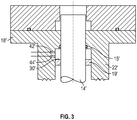
- FIG 3 An alternate embodiment of the invention is shown in figure 3 .
- the cavity 30' is formed below the flange 18' by providing a pair of spaced apart sealing arrangements on the shaft 14'.
- the shaft 14' may be an output extending from an actuator and connected in use to the valve stem.
- the shaft 14' may be integral with the valve stem.
- the shaft 14' may be considered to be a valve operator in the context of the present invention.
- the shaft 14' is contained within a shaft housing 22' which is contiguous with the valve stem passage of the valve.
- a cavity 30' is formed around the shaft 14' by the shaft housing 22' and a pair of sealing elements spaced axially apart along the length of the shaft 14'.
- the sealing elements comprise a primary seal formed by a pack 19' and a secondary seal (which may be a conventional shaft seal) 15'.
- the pack 19' is positioned below the shaft seal 15', but it will be appreciated that depending upon the particular arrangement of the housing 22' and shaft 14' the order/type of seals may be reversed.
- an annular cavity 30' having a fixed volume is defined between the shaft 14', housing 22' and seals 15' and 19'.
- Sensors 42' and 44' are provided and measure the temperature and pressure within the cavity 30' (although it will be appreciated that alternatively a single sensor may be arranged to sense both pressure and temperature). Data from the sensor(s) relating to pressure and temperature of within the chamber is provided to a processor as in the preceding embodiment and the change in pressure and change in temperature may be used to indicate a change in the substance (i.e. the amount of fluid) within the cavity and provide an indication of fugitive emissions.
- the cavity 30' may be provided with an overpressure vent to allow for controlled evacuation in the event of excess fugitive emissions.
- the housing 22' may be either formed integrally with the valve housing or may be attached to the housing in any convenient manner (with appropriate sealing provided).
- embodiments of the invention may provide an advantageous arrangement in which the valve operator include an integrated fugitive emissions detection arrangement.
- Advantages of embodiments may include one or more of the following:
Landscapes
- Engineering & Computer Science (AREA)
- General Engineering & Computer Science (AREA)
- Physics & Mathematics (AREA)
- General Physics & Mathematics (AREA)
- Mechanical Engineering (AREA)
- Indication Of The Valve Opening Or Closing Status (AREA)
- Examining Or Testing Airtightness (AREA)
Description
- This invention relates to a method and apparatus for fugitive emission detection and in particularly, but not exclusively, to a fugitive emission detection arrangement for use industrial valves.
- Industrial valves are very widely used globally to control the flow of fluids in manufacturing, civil services and other industries. For example, industrial valves may be used oil and gas, water and waste water, power, marine, mining, food, pharmaceutical and chemical industries. Industrial valves must be designed to minimise leakage. In particular as valves by their nature, necessitate some non-static seals they will present a potential leak location in any industrial flow system. Valve manufactures are constantly improving their products to reduce the risk but this cannot eliminate all risk of leakage. Such Leakage may lead to loss of profit/revenue, increased maintenance costs, increased process risk/risk to operators, risk of contamination (to the environment) and/or risk of contamination (to the fluid/product).
- These risks can be mitigated by implementing control methods in accordance with the principles of fugitive emissions control. According to numerous regional directive/regulations the suggested approach and/or best practice to fugitive emissions control by order of priority is as follows:
- i. Prevention by the selection of non-leaking or leak-tight equipment,
- ii. Monitoring for the detection of leaks,
- iii. Reparation of leaks as promptly as possible,
- iv. Continuous upgrading of leak prevention achievements.
- The present invention is directly intended to address the second issue, namely the monitoring and detection of leaks. This is commonly referred to in the art as "fugitive emission detection". It will, however, be appreciated that the third and fourth principles are directly impacted by the execution of the fugitive emission control and detection. As such, the skilled person would appreciate that an effective fugitive emission detection system could have a profound impact on the broader fugitive emission control processes.
- There are a number of existing approaches which are currently in use and/or commercially available for fugitive emission detection.
- Some techniques rely upon manual, labour intensive, detection. For example: Audible Noise detection in which an operator/inspector listening for unusual noises from equipment; the use of Gas Leak Spray in which a suspected leak area is sprayed with a spray and resulting in visible gas bubbles when a leak is present; or traditional valve isolation and inspection in which the valve is isolated and manually inspected (possibly as part of a preventative maintenance programme). Clearly these methods are labour intensive (often requiring specialist skilled labour), of limited accuracy and time consuming.
- Accordingly, there have been various developments which seek to automate or assist in the field of fugitive emission detection.
- One such development is described in
US Patent No. 6050296 , which describes a control apparatus. The control apparatus comprises an actuating drive and an actuator connected therewith, whereby the actuator comprises at least one valve face and a throttle element that works herewith. The throttle element can be moved relative to the valve face by means of an actuating spindle connected with the actuating drive for the execution of a rotational and/or piston motion. The actuating spindle is sealed against the valve interior chamber at a first sealing location. A second sealing location likewise seals the actuating spindle, and, between the two sealing locations. There is a test chamber that is accessible via at least one control terminal, to which chamber a pressure sensor is connected. The pressure sensor is connected with an evaluation unit for monitoring the operation of the control apparatus. The signal output of the pressure sensor can be compared, in the evaluation unit, with a response threshold dependent on at least one temperature signal, for the outputting of an error status message to an error status output of the evaluation unit. -
US Patent Publication No. 2015041000 describes a system to monitor performance of packing material in a seal. This document describes a system that can detect leaks that occur in seals, and in one example, to seals found in a valve. In one embodiment, the system utilises sensors that measure fluid properties of a sample volume proximate to the seal. The system can compare data from these measurements with data from a sample of a reference fluid (e.g., ambient air) to indicate the presence of working fluid in the sample volume. This result may indicate problems with the seal, e.g., degradation of the seal that is meant to prohibit the working fluid from migrating out of the valve. - Finally,
US Patent No. 5203370 describes an apparatus for mounting a rotary actuator, having a rotary drive bushing, to a valve stem of a rotary controlled valve having first and second primary seals and a fugitive fluid collection chamber therebetween. The apparatus includes a mounting member disposed between the actuator and the valve, which is removably fastened thereto, to permit the valve stem to coaxially engage the rotary drive bushing provided in the rotary actuator. O-rings are affixed to flanges that extend from the ends of the mounting member for creating a fluid-tight seal between the mounting member and the actuator and between the mounting member and the valve. The fluid-tight mounting member serves to provide a secondary fugitive fluid collection chamber outboard of the secondary stem seals that is adapted to collect the fugitive fluid that passes the secondary stem seals. A fluid detection device may be attached to the secondary fugitive fluid collection chamber via a port provided in the mounting member. - Gas Leak Detection Devices are available which may be handheld or worn by inspection personnel and measures the environment and emits an alarm upon sensing emissions. Inspections using such "sniffer" devices may be carried out at fixed intervals (with the intervals being determined based upon safety). Typically such devices are focused on the detection of dangerous levels of a volatile gas which could be harmful to the user.
- One of the more common systems is to use Infrared Temperature measurement tools. These tools measure and compare temperature values upstream and downstream of the valve. The Joule-Thomson effect states that both upstream and downstream temperatures must be equal; as such discrepancies between these values may be an indicator of fugitive emissions. However, not all leaks can be detected by this method (some leaks do not cause a measurable temperature differential). Further the external temperature readings of pipelines and fittings can be influenced by other external factors which may result in a loss of accuracy or even the ability to detect changes related to leaks altogether.
- A further detection system is Acoustic Emissions which utilises an indirect measure of turbulence within the valve (for example via a piezoelectric device) and can determine leakage based upon variations in the turbulence. Such systems only provide an indirect indication of leakage and require extensive tailoring to a particular valve. For example a large database of empirical data is needed to support the detection of changes and many variables in the detection need specific, detailed, knowledge of the particular valve and flow conditions.
- Finally, Ultrasonic Stethoscopes may be used to pass an ultrasonic wave through the valve to find possible leak paths. The efficiency of this method is currently unconfirmed. However, there are clear limitation/difficulties to this approach since listening frequency must be very carefully selected to filter out nearby noise. Accordingly, the use of Ultrasonic Stethoscopes requires a specifically trained and skilled operator.
- Thus, it will be appreciated that there remains a desire to provide an emission detection method and/or apparatus for assisting and/or automating fugitive emission detection, particularly fugitive emissions associated with valves. At least some embodiments of the present invention are intended to provide an alternative emission detection system which may address at least some of the disadvantages of some of the above described methods.
- In accordance with an embodiment of the invention there is provided a valve operator for a valve, the valve operator comprising:
- a valve operator housing comprising:
at least one cavity defined within the valve operator housing and positioned to be at least partially contiguous, in use, with a valve stem passage of the valve, the cavity having a fixed volume and being sealed from the exterior environment; and - the valve operator further comprising a fugitive emissions detector, the detector comprising:
- at least one sensor for measuring the pressure and temperature of the fluid within the interior of the cavity; and
- a processor comprising:
- an input for receiving data from the at least one sensor;
- a processing unit communicably connected to the input and configured to receive the data from the input and monitor the proportional change in the number of moles within the cavity by comparison of changes in temperature and pressure within the cavity;
- and an output for providing an indication of fugitive emissions when the processor indicates an increase in the number of moles within the cavity:
- characterised in that, the processor (40) determines the proportional change by calculating:


P 0 is the original cavity pressure (datum pressure);
P 1 is the measured cavity pressure;
T 0 is the original cavity temperature (datum temperature); and
T 1 is the measured cavity temperature and wherein:- if

- if

- if
- Also described herein is an industrial valve operator having an integrated valve fugitive emission detection arrangement.
- It may be appreciated that in the context of the invention an integrated fugitive emissions detection arrangement comprises the detector being at least partially integrated into the valve operator but the detector may optionally be integrated into a control/monitoring network. In some embodiments a local processing unit may be provided with/at the valve operator. Alternatively, a remote processor (for example a computer shared by a plurality of devices) may be utilised with the processor receiving data over a network.
- The valve may be an industrial valve.
- Accordingly embodiments of the invention may provide a valve operator having an integrated valve fugitive emission detection arrangement.
- The valve operator may be any known type of valve operator device which, the skilled person will appreciate would ordinarily be attached to an industrial valve to engage the valve stem and provide a means for controlling and actuating the valve in use. For example, the simplest form of valve operator may be a simple actuation lever or hand-wheel. Alternatively the operator could be a valve actuator, for example the valve operator could be any of an electric, Pneumatic or Hydraulic actuator. The valve operator may also be an intermediate component in a valve actuation system, for example a gearbox or adaptor. Such intermediate components may be attached to an industrial valve (to engage the valve stem) and then in turn be connected to a valve actuator or the like.
- The skilled person will be aware that various such valve operators are readily commercially available from Rotork PLC group of companies. Advantageously, embodiments of the invention may be easily incorporated into such known devices with only relatively minimal modification.
- The invention is predicated, at least in part, on the Applicants' recognition that the static seals in the valve and/or valve operator are highly reliable (and can nominally be considered to be a perfect seal) whereas a rotating seal such as that provided at the valve stem is unavoidably less reliable (and, therefore, typically requires more regular maintenance and inspection). As such, it is possible to anticipate that the leak path of fugitive emissions from the valve will pass through the valve stem passage (and typically through the rotational seals provided across the passage to close the space between the stem and valve housing) to the valve operator, as the path of least resistance.
- By providing a cavity which is at least partially contiguous, in use, with the valve stem passage, the cavity will receive any such fugitive emissions. Advantageously, embodiments of the invention allow monitoring/detection to be carried out at the valve operator, rather than at the valve itself, which will almost always be in a more convenient and/or readily accessible location. Even though embodiments may allow the detection to be carried out at a more convenient location it is also an advantage that, unlike many prior art methods (such as Infrared Temperature or Acoustic Emissions), embodiments of the invention enable direct testing of leaking fluid.
- Furthermore, it will be appreciated that valve operators are generally easily replaced or upgraded (whereas the valve may be in a flow which needs continuous operation). For example valve operators may generally be configured for attachment onto standardised valve flanges. Thus, a valve operator in accordance with embodiments of the invention may readily be retrofitted to existing industrial valves.
- In particular the at least one sensor may measure the temperature and pressure within the cavity. The at least one sensor may be provided internally to the valve operator. The at one least sensor may generally be direct in communication with the interior of the cavity.
- It will be appreciated that the pressure and temperature in a volume are related directly to the amount of substance present within the volume (as expressed in the ideal gas law). The volume of the cavity in the valve operator is known. Further, the volume is typically constant. Measurement of the pressure and temperature can be used to provide an indication of any change in the amount of substance within the cavity. As the cavity is generally sealed when installed on a valve (other than being at least partially contiguous with a valve stem passage of the industrial valve) any change detected in the cavity can be assumed to have escaped from the valve stem housing (i.e. having leaked past a valve stem seal). Thus, the detection of a change in the cavity may be used as a direct measure indicative of fugitive emissions from the valve.
- In order to ensure that the effective volume of the cavity remains constant it is important to ensure a good seal between the cavity and the exterior whilst keeping the cavity in fluid communication with the leak path from the valve stem passage. This seal is provided by engagement between a flange of the valve and the sealing face of the valve operator. The sealing face of the valve operator may include at least one resilient sealing member, for example an O-ring. The resilient seal member may be compressed between opposing portions of the flange and sealing face in use to provide an effective seal.
- A fugitive emissions detection arrangement in accordance with some embodiments of the invention may only be required to detect a change in the amount (generally an increase) of substance in the chamber (to detect a leak) rather than determine the actual quantity of any such change. This may simplify the implementation of the embodiment since, if the volume of the cavity is constant, it is not necessary to know or measure the actual cavity volume. This may for example, advantageously eliminate any errors or calibration required due to tolerances in manufacturing.
- The cavity may be provided with an overpressure vent outlet. The vent outlet may ensure that the fluid pressure within the cavity cannot exceed a predetermined nominal safe pressure value. If the pressure exceeds the nominal safe pressure value the overpressure vent outlet will allow fluid from the cavity to be vented to the external atmosphere. The predetermined nominal safe pressure may be selected to be sufficiently low to ensure that damage will not occur to the valve operator. The predetermined nominal safe pressure value may be selected to be in excess of the sensitivity of the fugitive emissions detection. As such, in normal operation any fugitive emissions would be expected to be detected by the system in advance of the need for the system to vent (and action may be possible to prevent the emissions prior to the pressure in the housing reaching the nominal safe pressure). The overpressure vent outlet may for example comprise a valve or burst diaphragm to allow venting when the selected nominal safe pressure is reached or exceeded.
- The valve operator may further comprise a processor for receiving data from the at least one sensor and for determining whether they are indicative of fugitive emissions. The processor may be local to the valve operator or could be remotely located (for example as part of a networked system). Locating the processor locally may advantageously allow the system to provide a local indication of the detection of fugitive emissions (for example in addition to sending a signal to a monitoring or control system such that redundancy is provided).
- The processor may for example be arranged to receive pressure and temperature measurements relating to the cavity from the at least one sensor and determine whether any change in substance within the cavity has occurred. The values of P0 and T0 may be recorded by the processor when the device is re-set. For example a re-set button or function may be provided which causes the process to record sense values as the datum value for both pressure and temperature.
- The valve operator may be provided with a network module (for example a receiver/transmitter connected to a processor). This may for example allow integration of the fugitive emissions detection into a control or monitoring network. The network transmitter could for example be configured to be connected into a conventional wired or wireless field network. For example, the network transmitter could be arranged to be compatible with the Pakscan system available from Rotork.
- Providing networked fugitive emissions detection arrangements may advantageously allow for live and continuous monitoring. Further, the system may reduce fugitive emissions to the environment by providing prompt notification or flagging of any valve errors.
- The valve operator in embodiments of the invention may include additional sensor devices for detecting the operational status of the valve and/or valve operator. For example, a position indicator could be provided to determine the stroke position of the valve. This information may be integrated with the monitored data from the position sensors (for example in the processor). This may enable the data from the fugitive emissions detection to be utilised for additional diagnostic purposes. For example, a monitoring or control system may be able to utilise the position sensor information along with fugitive emissions detection to correlate the stage/position of the valve operation at which emissions are occurring.
- The valve operator housing defining the housing may at least partially house the components of the valve operator. For example it may be a cast housing. The housing may for example be a housing meeting a required environmental sealing standard.
- The skilled person will appreciate that, although it may be less commercially useful, the valve operator and valve could be integrally formed without altering the underlying principle of the integration of the fugitive emissions detection into the valve operator portion of the valve assembly.
- According to a further embodiment of the invention there is provided a method of providing a fugitive emissions detection arrangement for a valve, the method comprising:
- providing a valve operator including an integral fugitive emissions detection;
- sealingly connecting the valve operator to the valve such that the valve operator is in the leak path for fugitive emissions and
- monitoring the fluid conditions within the valve operator to detecting fugitive emissions.
- The method may be a method of retrofitting. Accordingly, the step of providing a valve operator may comprise the additional step of removing an existing valve operator.
- The valve operator is a valve operator in accordance with any embodiment of the invention.
- The method may further comprise connecting the valve operator to a control network.
- The step of monitoring the fluid conditions may comprise monitoring changes in pressure and/or temperature within a portion of the valve operator to provide an indication of any fugitive emissions.
- A specific embodiment of the invention will now be described in detail, by way of example only, and with reference to the accompanying drawings in which:
-
Figure 1 schematically illustrating a valve and valve operator in accordance with an embodiment of the invention; and -
Figure 2 schematically illustrates a cross sectional view of a fugitive emission detection arrangement provided in a valve operator in accordance with an embodiment of the invention; -
Figure 3 schematically illustrates a cross sectional view of a fugitive emission detection arrangement provided in a valve operator in accordance with an alternative embodiment of the invention. -
Figure 1 shows a typicalindustrial valve assembly 10 which may be used to control the flow of fluids in industrial applications. For example, thevalve assembly 10 could be used oil and gas, water and waste water, power, marine, mining, food, pharmaceutical and chemical industries. The valve assembly comprises avalve 10 including avalve member 12, connected to avalve actuation stem 14. The valve could for example be a quarter turn valve or a multi-turn valve arrangement. - The
valve member 12 and stem 14 are provided within ahousing 16. The upper portion of thehousing 16 comprises avalve stem passage 17 and terminates at aflange 18. At least onestem seal 15 is provided between thestem passage 17 andstem 14 and is intended to prevent the escape of fluid from thevalve housing 16 in use. As thestem seal 15 is a non-static seal (as thestem 14 will generally rotate relative to thepassage 17 during actuation) it provides a less reliable seal than static seals (for example those between the valve housing and the associated pipe or conduit. Thus, when a leakage occurs at the valve thestem seal 15 is the path of least resistance and fugitive emissions will be expected to pass beyond theseal 15 and out of thestem passage 17. - The valve assembly 1 also includes a
valve operator 20. Thevalve operator 20 drivingly engages an upper drive portion of thevalve stem 14 and provides a means for controlling and actuating thevalve member 12 in use. Thevalve operator 20 is provided within avalve operator housing 22 which is arranged to be connected to thevalve housing 16 via theflange 18. In its simplest form the valve operator could be a manual operator such as a hand-wheel (which may include an associated gearing arrangement). In the example ofFigure 1 the valve operator represents an electrical valve actuator (for example one of the IQ actuator range available form Rotork Controls Limited). In some embodiments the valve operator may also be an intermediate component in a valve actuation system; for example a gearbox or adaptor which is connected to thevalve flange 18 to drivingly engage thestem 14 but which in turn receives a further actuator to power and or control the intermediate component. - As best seen in the schematic partial cross section of
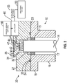
Figure 2 , in accordance with embodiments of the invention, thevalve operator 20 is provided with an integral fugitive emissions detection system (the components and operation of which will be described below). - The
valve operator 20 is connected to thevalve flange 18 in any conventional manner. The mating surface of thevalve operator housing 22 provides a sealingface 23 which abuts the corresponding upper face of the valve flange. The sealing face is provided with at least one sealingmember 24, for example an O-ring received in a recess 25. With thevalve operator 20 mounted on thevalve housing 16, the sealing arrangement effectively forms a seal around the upper end of thevalve stem passage 17. - The
valve operator 20 is provided with acavity 30 which is defined within the interior of thehousing 22. Thecavity 30 may have any convenient shape or profile. Thecavity 30 shape will depend upon theparticular valve operator 20 and may for example be formed of a plurality of interlinked sub-cavities or chambers. However, regardless of the particular profile, at least aportion 32 of thecavity 30 must be contiguous with thevalve stem passage 17 when the valve operator has been installed on thevalve 10. Due to the sealing aroundflange 18 and the sealing surface 23 (which is a static seal so can be considered to allow a nominally perfect seal), thecavity 30 defined by thehousing 22 is the only outlet (via the contiguous portion 32) from thestem passage 17 if fugitive emissions escape beyond thestem seal 15. - To prevent dangerous pressure levels developing within the
cavity 30, anoverpressure outlet 34 is provided to enable venting of the, normally sealed,cavity 30 to the external atmosphere. Apressure controller 35 such as a valve or rupture diaphragm closes theoverpressure outlet 34 during normal operation such that venting only occurs at a predetermined pressure based upon a nominal safety value for the pressure within thehousing 22 of theoperator 20. The operation of the fugitive emissions arrangement will, during normal operation, be unaffected by the presence of theoverpressure outlet 34 as the sensitivity of the fugitive emissions detection can be selected to be significantly below the level of fugitive emissions which would be required to result in an overpressure situation. - A
temperature 42 andpressure 44 sensor are provided within thevalve operator 20 and configured to allow direct monitoring of the fluid within thecavity 30. Thetemperature 42 andpressure 44 sensors provide information on the conditions within thecavity 30 to a processor 40 (which may for example be a logic solver). In the illustrated embodiment theprocessor 40 is locally provided integral to thevalve operator 20. It will, however, be appreciated that alternatively raw date could be transmitted to a remote control or monitoring location which could include the processor. The valve operator may optionally be provided with additional status sensors such as avalve position sensor 46, which may be connected to anencoder device 42. - To allow for monitoring of multiple valve devices, and preferable live and continuous monitoring, the
processor 40 may be provided with a network module or transmitter to interface with aremote monitoring system 55. For example the processor may connect via afield network 55 which could be either a wired or wireless system. - Once the
valve operator 20 in accordance with an embodiment has been installed on avalve 10 the pressure and temperature information provided by thesensors processor 40 to detect fugitive emissions. - The processor utilises the Ideal Gas Law:

- P
- Pressure (Pa)
- V
- Volume (m3)
- n
- Chemical Amount (mol)
- R
- Ideal Gas Constant
- T
- Temperature (K)
- On the
valve operator 20, the Volume V of thecavity 30 is constant. Further, the fugitive emissions detection is only required to determine a proportional change in the number of moles (i.e. not the absolute number) in order to detect a leak. - Thus, the following equation can be derived:


P 0 is the original cavity pressure (i.e. a datum pressure);
P 1 is the current (measured) cavity pressure;
T 0 is the original cavity temperature (i.e. a datum temperature); and
T 1 is the current cavity temperature. if
- As a result, the
processor 40 may calculate any proportional change in n within thecavity 30 using the readings for P and T provided by the sensors within thevalve operator cavity 30 from thevalve stem passage 17. - It is important to note that by assuming the volume of the cavity is constant the implementation of embodiments of the invention on different valve and valve operators is greatly simplified since the
processor 40 need only measure changes in pressure and temperature. - An alternate embodiment of the invention is shown in
figure 3 . In this embodiment the cavity 30' is formed below the flange 18' by providing a pair of spaced apart sealing arrangements on the shaft 14'. It will be appreciated that the shaft 14' may be an output extending from an actuator and connected in use to the valve stem. The shaft 14' may be integral with the valve stem. The skilled person will appreciate that the shaft 14' may be considered to be a valve operator in the context of the present invention. - The shaft 14' is contained within a shaft housing 22' which is contiguous with the valve stem passage of the valve. A cavity 30' is formed around the shaft 14' by the shaft housing 22' and a pair of sealing elements spaced axially apart along the length of the shaft 14'. In the illustrated embodiment the sealing elements comprise a primary seal formed by a pack 19' and a secondary seal (which may be a conventional shaft seal) 15'. The pack 19' is positioned below the shaft seal 15', but it will be appreciated that depending upon the particular arrangement of the housing 22' and shaft 14' the order/type of seals may be reversed. Thus an annular cavity 30' having a fixed volume is defined between the shaft 14', housing 22' and seals 15' and 19'.
- Sensors 42' and 44' are provided and measure the temperature and pressure within the cavity 30' (although it will be appreciated that alternatively a single sensor may be arranged to sense both pressure and temperature). Data from the sensor(s) relating to pressure and temperature of within the chamber is provided to a processor as in the preceding embodiment and the change in pressure and change in temperature may be used to indicate a change in the substance (i.e. the amount of fluid) within the cavity and provide an indication of fugitive emissions.
- It will be appreciated that other features of the first embodiment may be incorporated into the second embodiment. For example the cavity 30' may be provided with an overpressure vent to allow for controlled evacuation in the event of excess fugitive emissions. Further it will be appreciated that the housing 22' may be either formed integrally with the valve housing or may be attached to the housing in any convenient manner (with appropriate sealing provided).
- It will be appreciated from the above description that embodiments of the invention may provide an advantageous arrangement in which the valve operator include an integrated fugitive emissions detection arrangement. Advantages of embodiments may include one or more of the following:
- No labour input being required after commission - information is relayed via a field network (wired or wireless) to appropriate personnel. This information will be live and continuous.
- Direct detection of leaking fluid.
- Embodiments may be used as a diagnostic tool which can lead to improved and more effective asset management.
- Embodiments may aid in reducing volume of fluid released to the environment by fugitive emissions via prompt notification to appropriate personnel. This could lead to significant reductions in the severity of any leaks and the timely repair or replacement of leaking equipment.
- The detection does not rely on previous empirical data.
- Minimises the need for preventative maintenance.
- Does not require specific knowledge of the valve.
- Not affected by external noise.
- Can be used for a variety of fluids.
- Does not interfere with valve operation (i.e. has no effect on the production process)
- Although the invention has been described above with reference to a preferred embodiment, it will be appreciated that various changes or modifications may be made without departing from the scope of the invention as defined in the appended claims. For example, whilst the described embodiment utilises a single cavity to detect fugitive emissions, the skilled person could readily envisage that in a system requiring redundancy it may be possible to define a plurality of cavities and to apply the methodology of the invention to each cavity independently.
Claims (15)
- A valve operator (20) for a valve (10), the valve operator (20) comprising:a valve operator housing (22,22') comprising:at least one cavity (30,30') defined within the valve operator housing (22,22') and positioned to be at least partially contiguous (32), in use, with a valve stem passage (17) of the valve (10), the cavity (30,30') having a fixed volume and being sealed from the exterior environment; andthe valve operator (20) further comprising a fugitive emissions detector, the detector comprising:at least one sensor (42,42',44,44') for measuring the pressure and temperature of the fluid within the interior of the cavity; anda processor (40) comprising:an input for receiving data from the at least one sensor (42,42',44,44');a processing unit communicably connected to the input and configured to receive the data from the input and monitor the proportional change in the number of moles within the cavity (30,30') by comparison of changes in temperature and pressure within the cavity (30,30'); andan output for providing an indication of fugitive emissions when the processor (40) indicates an increase in the number of moles within the cavity (30,30');characterised in that, the processor (40) determines the proportional change by calculating:

 P 0 is the original cavity pressure (datum pressure)P 1 is the measured cavity pressure;T 0 is the original cavity temperature (datum temperature); andT 1 is the measured cavity temperature.and wherein:if
 if
if
- A valve operator (20) as claimed in claim 1, wherein the valve (10) is an industrial valve.
- A valve operator (20) as claimed in either claim 1 or 2, wherein the at least one sensor (42,42',44,44') is in direct communication with the interior of the cavity (30,30').
- A valve operator (20) as claimed in any preceding claim, wherein the at least one cavity (30,30') is provided with an overpressure vent outlet (34) .
- A valve operator (20) as claimed in claim 4, wherein the overpressure vent outlet (34) comprises a pressure controller (35), such as a valve or rupture diaphragm, which closes the overpressure vent outlet (34) during normal operation, such that venting only occurs at a predetermined pressure based upon a nominal safety value for the pressure within the housing (22) of the operator (20).
- A valve operator (20) as claimed in any preceding claim, wherein the processor (40) is local to the valve operator (20).
- A valve operator (20) as claimed in any preceding claim, wherein the processor (40) comprises a re-set function to record P0 and T0 as the datum values for both pressure and temperature.
- A valve operator (20) as claimed in any preceding claim, further comprising a network module.
- A valve operator (20) as claimed in any preceding claim, wherein the valve operator housing (22,22') further comprises a sealing face (23) configured, in use, to sealing engage a flange (18), the flange (18) being provided on the valve (10) and surrounding the valve stem passage (17), so as to isolate the cavity (30,30'), or cavities, from the external environment when mounted to the flange (18).
- A valve operator (20) as claimed in claim 9, wherein the sealing face (23) of the valve operator (20) includes at least one resilient sealing member (24).
- A valve operator (20) as claimed in any preceding claim, wherein the processor (40) is configured to determine a change by monitoring changes in pressure relative to changes of temperature within the cavity (30,30').
- A valve operator (20) as claimed in any preceding claim, further comprising additional sensor devices (46) for detecting the operational status of the valve (10) and/or valve operator (20).
- A valve operator (20) as claimed in any preceding claim, further comprising a motor for rotating a drive shaft in use, and an output driven by the drive shaft and arranged for driving the valve stem (14) of a valve (10) in use.
- A valve operator (20) as claimed in claim 11, wherein the output comprises a gear, which may for example be driven by a worm associated with the drive shaft.
- A method of detecting fugitive emissions from a valve operator (20) as claimed in any preceding claim, the method comprising:providing a valve operator housing (22,22'), having a cavity (30,30') with a fixed internal volume, the cavity (30,30') being in fluid communication with a leak path from a valve stem passage (17) of the valve (10),isolating the cavity (30,30') from the external environment;measuring the pressure and temperature within the cavity (30,30'); andmonitoring for proportional changes in the number of moles in the cavity (30,30') using the detected change in pressure and detected change in temperature within the cavity (30,30');characterised in that, the step of deriving the proportional change in the number of moles in the cavity (30,30') comprises calculating:

 P 0 is the original cavity pressure (a datum pressure);P 1 is the measured cavity pressure;T 0 is the original cavity temperature (a datum temperature); andT 1 is the measured cavity temperature,and wherein:

Applications Claiming Priority (2)
| Application Number | Priority Date | Filing Date | Title |
|---|---|---|---|
| GBGB1604656.7A GB201604656D0 (en) | 2016-03-18 | 2016-03-18 | Fugitive emission detection |
| PCT/GB2017/050753 WO2017158380A1 (en) | 2016-03-18 | 2017-03-17 | Fugitive emission detection |
Publications (2)
| Publication Number | Publication Date |
|---|---|
| EP3430367A1 EP3430367A1 (en) | 2019-01-23 |
| EP3430367B1 true EP3430367B1 (en) | 2020-05-06 |
Family
ID=55968557
Family Applications (1)
| Application Number | Title | Priority Date | Filing Date |
|---|---|---|---|
| EP17713064.8A Active EP3430367B1 (en) | 2016-03-18 | 2017-03-17 | Fugitive emission detection |
Country Status (9)
| Country | Link |
|---|---|
| US (1) | US10962440B2 (en) |
| EP (1) | EP3430367B1 (en) |
| JP (1) | JP6675515B2 (en) |
| KR (1) | KR102086706B1 (en) |
| CN (1) | CN109196325A (en) |
| BR (1) | BR112018068985A2 (en) |
| GB (1) | GB201604656D0 (en) |
| RU (1) | RU2712955C1 (en) |
| WO (1) | WO2017158380A1 (en) |
Families Citing this family (11)
| Publication number | Priority date | Publication date | Assignee | Title |
|---|---|---|---|---|
| WO2019169075A1 (en) | 2018-02-28 | 2019-09-06 | Davis Edward P | Manual override system for magnetically actuated valves |
| US11047499B2 (en) | 2018-02-28 | 2021-06-29 | Edward P. Davis | Valve actuation conversion kit |
| IT201900015231A1 (en) * | 2019-08-29 | 2021-03-01 | Cavagna Group Spa | VALVE WITH INTEGRATED SENSOR |
| AU2020419312A1 (en) | 2020-01-03 | 2022-07-14 | Bray International, Inc. | Valve with load cell |
| CN111350860A (en) * | 2020-04-10 | 2020-06-30 | 武汉格莱特控制阀有限公司 | Electric valve with pressure measuring function |
| RU2760167C1 (en) * | 2020-12-22 | 2021-11-22 | Общество с ограниченной ответственностью "Газпром трансгаз Ухта" | Intelligent system for determining technical condition of pipeline valves |
| CN113309865B (en) * | 2021-05-31 | 2023-11-24 | 涿州市烽合机械设备有限公司 | Hydrogen valve with leak hydrogen and get rid of function |
| US12038351B2 (en) * | 2021-12-31 | 2024-07-16 | Dresser, Llc | Detecting emissions from valve packing |
| CN114544097A (en) * | 2022-01-12 | 2022-05-27 | 合肥通用机械研究院有限公司 | Valve dispersion test device |
| CN115090557B (en) * | 2022-07-04 | 2023-10-31 | 宁波友谊铜业有限公司 | Full-automatic air tightness detection device and detection method for pipe joint |
| US12345609B2 (en) | 2022-11-29 | 2025-07-01 | Dresser, Llc | Detecting fugitive emissions with a valve positioner |
Citations (3)
| Publication number | Priority date | Publication date | Assignee | Title |
|---|---|---|---|---|
| US5203370A (en) * | 1991-11-26 | 1993-04-20 | Block Gary C | Mounting apparatus with fugitive emission collection means for directly coupling a rotary valve to an actuator having rotary drive means |
| US6050296A (en) * | 1997-06-03 | 2000-04-18 | Samson Aktiengesellschaft | Control apparatus |
| US20150041000A1 (en) * | 2013-08-07 | 2015-02-12 | Dresser, Inc. | System to monitor performance of packing material in a seal |
Family Cites Families (13)
| Publication number | Priority date | Publication date | Assignee | Title |
|---|---|---|---|---|
| US4901751A (en) * | 1989-06-15 | 1990-02-20 | Systems Chemistry, Inc. | Fluid control valve and system with leak detection and containment |
| US4972867A (en) | 1989-11-03 | 1990-11-27 | Ruesch J O | Valve stem seal leak protection and detection apparatus |
| DE4326343A1 (en) | 1993-08-05 | 1995-02-09 | Honeywell Ag | Diganose system for control and shut-off valves |
| US5616829A (en) * | 1995-03-09 | 1997-04-01 | Teledyne Industries Inc. | Abnormality detection/suppression system for a valve apparatus |
| CN1894526A (en) * | 2003-10-17 | 2007-01-10 | 松德沃技术公司 | Fail safe pneumatically actuated valve |
| US7367544B2 (en) * | 2004-12-17 | 2008-05-06 | Tac, Llc | Apparatus and method for replacing existing actuator zone valves in an HVAC system with a ball valve |
| JP4998217B2 (en) | 2007-11-08 | 2012-08-15 | パナソニック株式会社 | Fluid shut-off device |
| US8036837B2 (en) * | 2008-02-29 | 2011-10-11 | Fisher Controls International Llc | Diagnostic method for detecting control valve component failure |
| JP5499570B2 (en) | 2009-08-31 | 2014-05-21 | 日産自動車株式会社 | Electric vehicle drive device |
| US9316323B2 (en) * | 2012-06-14 | 2016-04-19 | Fisher Controls International Llc | Hydraulic mechanism for valves |
| FR2993659B1 (en) * | 2012-07-23 | 2014-08-08 | Adixen Vacuum Products | DETECTION METHOD AND PLANT FOR THE SEALING OF SEALED PRODUCT PACKAGES |
| CN202928762U (en) * | 2012-11-30 | 2013-05-08 | 天津市中环电子计算机有限公司 | Portable tester for automatic quantification measurement of airtightness |
| AU2014228946B2 (en) * | 2013-03-15 | 2019-04-04 | Deka Products Limited Partnership | System, method, and apparatus for monitoring, regulating, or controlling fluid flow |
-
2016
- 2016-03-18 GB GBGB1604656.7A patent/GB201604656D0/en not_active Ceased
-
2017
- 2017-03-17 CN CN201780017643.9A patent/CN109196325A/en active Pending
- 2017-03-17 JP JP2019500031A patent/JP6675515B2/en not_active Expired - Fee Related
- 2017-03-17 WO PCT/GB2017/050753 patent/WO2017158380A1/en active Application Filing
- 2017-03-17 RU RU2018135855A patent/RU2712955C1/en active
- 2017-03-17 EP EP17713064.8A patent/EP3430367B1/en active Active
- 2017-03-17 KR KR1020187030156A patent/KR102086706B1/en active Active
- 2017-03-17 US US16/085,244 patent/US10962440B2/en active Active
- 2017-03-17 BR BR112018068985A patent/BR112018068985A2/en not_active IP Right Cessation
Patent Citations (3)
| Publication number | Priority date | Publication date | Assignee | Title |
|---|---|---|---|---|
| US5203370A (en) * | 1991-11-26 | 1993-04-20 | Block Gary C | Mounting apparatus with fugitive emission collection means for directly coupling a rotary valve to an actuator having rotary drive means |
| US6050296A (en) * | 1997-06-03 | 2000-04-18 | Samson Aktiengesellschaft | Control apparatus |
| US20150041000A1 (en) * | 2013-08-07 | 2015-02-12 | Dresser, Inc. | System to monitor performance of packing material in a seal |
Also Published As
| Publication number | Publication date |
|---|---|
| JP2019509502A (en) | 2019-04-04 |
| CN109196325A (en) | 2019-01-11 |
| US10962440B2 (en) | 2021-03-30 |
| KR20180127422A (en) | 2018-11-28 |
| EP3430367A1 (en) | 2019-01-23 |
| GB201604656D0 (en) | 2016-05-04 |
| KR102086706B1 (en) | 2020-03-09 |
| US20190078965A1 (en) | 2019-03-14 |
| RU2712955C1 (en) | 2020-02-03 |
| BR112018068985A2 (en) | 2019-01-22 |
| WO2017158380A1 (en) | 2017-09-21 |
| JP6675515B2 (en) | 2020-04-01 |
Similar Documents
| Publication | Publication Date | Title |
|---|---|---|
| EP3430367B1 (en) | Fugitive emission detection | |
| EP2257724B1 (en) | Diagnostic method for detecting control valve component failure | |
| JP5547945B2 (en) | Pressure relief valve monitoring | |
| EP1931962B1 (en) | Leak detector for process valve | |
| CN103575479A (en) | Apparatus for fluid control device leak detection | |
| US20080012236A1 (en) | Packing case seal | |
| CN211904570U (en) | Industrial process differential pressure sensing device and pressure sensor isolation device | |
| KR102162196B1 (en) | Industrial Valve Gas Leak Prediction System | |
| WO2013172730A1 (en) | A system for monitoring the condition of a pipeline for gas and/or fluid | |
| KR101409487B1 (en) | System for detecting inside leakage of valve | |
| US20230213406A1 (en) | Detecting emissions from valve packing | |
| EP3914843B1 (en) | Abnormal condition detection of shut down valves and blow down valves | |
| JP2024119187A (en) | Valve maintenance support device and support method | |
| Meland | Condition evaluation of safety critical shut-down valves | |
| Smahi et al. | Conception Of a Professional Mobile Workshop for Industrial Instruments |
Legal Events
| Date | Code | Title | Description |
|---|---|---|---|
| STAA | Information on the status of an ep patent application or granted ep patent |
Free format text: STATUS: UNKNOWN |
|
| STAA | Information on the status of an ep patent application or granted ep patent |
Free format text: STATUS: THE INTERNATIONAL PUBLICATION HAS BEEN MADE |
|
| PUAI | Public reference made under article 153(3) epc to a published international application that has entered the european phase |
Free format text: ORIGINAL CODE: 0009012 |
|
| STAA | Information on the status of an ep patent application or granted ep patent |
Free format text: STATUS: REQUEST FOR EXAMINATION WAS MADE |
|
| 17P | Request for examination filed |
Effective date: 20180829 |
|
| AK | Designated contracting states |
Kind code of ref document: A1 Designated state(s): AL AT BE BG CH CY CZ DE DK EE ES FI FR GB GR HR HU IE IS IT LI LT LU LV MC MK MT NL NO PL PT RO RS SE SI SK SM TR |
|
| AX | Request for extension of the european patent |
Extension state: BA ME |
|
| DAV | Request for validation of the european patent (deleted) | ||
| DAX | Request for extension of the european patent (deleted) | ||
| GRAP | Despatch of communication of intention to grant a patent |
Free format text: ORIGINAL CODE: EPIDOSNIGR1 |
|
| STAA | Information on the status of an ep patent application or granted ep patent |
Free format text: STATUS: GRANT OF PATENT IS INTENDED |
|
| INTG | Intention to grant announced |
Effective date: 20191112 |
|
| GRAS | Grant fee paid |
Free format text: ORIGINAL CODE: EPIDOSNIGR3 |
|
| GRAA | (expected) grant |
Free format text: ORIGINAL CODE: 0009210 |
|
| STAA | Information on the status of an ep patent application or granted ep patent |
Free format text: STATUS: THE PATENT HAS BEEN GRANTED |
|
| AK | Designated contracting states |
Kind code of ref document: B1 Designated state(s): AL AT BE BG CH CY CZ DE DK EE ES FI FR GB GR HR HU IE IS IT LI LT LU LV MC MK MT NL NO PL PT RO RS SE SI SK SM TR |
|
| REG | Reference to a national code |
Ref country code: GB Ref legal event code: FG4D |
|
| REG | Reference to a national code |
Ref country code: CH Ref legal event code: EP Ref country code: AT Ref legal event code: REF Ref document number: 1267547 Country of ref document: AT Kind code of ref document: T Effective date: 20200515 |
|
| REG | Reference to a national code |
Ref country code: IE Ref legal event code: FG4D |
|
| REG | Reference to a national code |
Ref country code: DE Ref legal event code: R096 Ref document number: 602017016250 Country of ref document: DE |
|
| REG | Reference to a national code |
Ref country code: LT Ref legal event code: MG4D |
|
| REG | Reference to a national code |
Ref country code: NL Ref legal event code: MP Effective date: 20200506 |
|
| PG25 | Lapsed in a contracting state [announced via postgrant information from national office to epo] |
Ref country code: IS Free format text: LAPSE BECAUSE OF FAILURE TO SUBMIT A TRANSLATION OF THE DESCRIPTION OR TO PAY THE FEE WITHIN THE PRESCRIBED TIME-LIMIT Effective date: 20200906 Ref country code: PT Free format text: LAPSE BECAUSE OF FAILURE TO SUBMIT A TRANSLATION OF THE DESCRIPTION OR TO PAY THE FEE WITHIN THE PRESCRIBED TIME-LIMIT Effective date: 20200907 Ref country code: GR Free format text: LAPSE BECAUSE OF FAILURE TO SUBMIT A TRANSLATION OF THE DESCRIPTION OR TO PAY THE FEE WITHIN THE PRESCRIBED TIME-LIMIT Effective date: 20200807 Ref country code: FI Free format text: LAPSE BECAUSE OF FAILURE TO SUBMIT A TRANSLATION OF THE DESCRIPTION OR TO PAY THE FEE WITHIN THE PRESCRIBED TIME-LIMIT Effective date: 20200506 Ref country code: NO Free format text: LAPSE BECAUSE OF FAILURE TO SUBMIT A TRANSLATION OF THE DESCRIPTION OR TO PAY THE FEE WITHIN THE PRESCRIBED TIME-LIMIT Effective date: 20200806 Ref country code: SE Free format text: LAPSE BECAUSE OF FAILURE TO SUBMIT A TRANSLATION OF THE DESCRIPTION OR TO PAY THE FEE WITHIN THE PRESCRIBED TIME-LIMIT Effective date: 20200506 Ref country code: LT Free format text: LAPSE BECAUSE OF FAILURE TO SUBMIT A TRANSLATION OF THE DESCRIPTION OR TO PAY THE FEE WITHIN THE PRESCRIBED TIME-LIMIT Effective date: 20200506 |
|
| PG25 | Lapsed in a contracting state [announced via postgrant information from national office to epo] |
Ref country code: BG Free format text: LAPSE BECAUSE OF FAILURE TO SUBMIT A TRANSLATION OF THE DESCRIPTION OR TO PAY THE FEE WITHIN THE PRESCRIBED TIME-LIMIT Effective date: 20200806 Ref country code: HR Free format text: LAPSE BECAUSE OF FAILURE TO SUBMIT A TRANSLATION OF THE DESCRIPTION OR TO PAY THE FEE WITHIN THE PRESCRIBED TIME-LIMIT Effective date: 20200506 Ref country code: RS Free format text: LAPSE BECAUSE OF FAILURE TO SUBMIT A TRANSLATION OF THE DESCRIPTION OR TO PAY THE FEE WITHIN THE PRESCRIBED TIME-LIMIT Effective date: 20200506 Ref country code: LV Free format text: LAPSE BECAUSE OF FAILURE TO SUBMIT A TRANSLATION OF THE DESCRIPTION OR TO PAY THE FEE WITHIN THE PRESCRIBED TIME-LIMIT Effective date: 20200506 |
|
| REG | Reference to a national code |
Ref country code: AT Ref legal event code: MK05 Ref document number: 1267547 Country of ref document: AT Kind code of ref document: T Effective date: 20200506 |
|
| PG25 | Lapsed in a contracting state [announced via postgrant information from national office to epo] |
Ref country code: NL Free format text: LAPSE BECAUSE OF FAILURE TO SUBMIT A TRANSLATION OF THE DESCRIPTION OR TO PAY THE FEE WITHIN THE PRESCRIBED TIME-LIMIT Effective date: 20200506 Ref country code: AL Free format text: LAPSE BECAUSE OF FAILURE TO SUBMIT A TRANSLATION OF THE DESCRIPTION OR TO PAY THE FEE WITHIN THE PRESCRIBED TIME-LIMIT Effective date: 20200506 |
|
| PG25 | Lapsed in a contracting state [announced via postgrant information from national office to epo] |
Ref country code: AT Free format text: LAPSE BECAUSE OF FAILURE TO SUBMIT A TRANSLATION OF THE DESCRIPTION OR TO PAY THE FEE WITHIN THE PRESCRIBED TIME-LIMIT Effective date: 20200506 Ref country code: DK Free format text: LAPSE BECAUSE OF FAILURE TO SUBMIT A TRANSLATION OF THE DESCRIPTION OR TO PAY THE FEE WITHIN THE PRESCRIBED TIME-LIMIT Effective date: 20200506 Ref country code: EE Free format text: LAPSE BECAUSE OF FAILURE TO SUBMIT A TRANSLATION OF THE DESCRIPTION OR TO PAY THE FEE WITHIN THE PRESCRIBED TIME-LIMIT Effective date: 20200506 Ref country code: SM Free format text: LAPSE BECAUSE OF FAILURE TO SUBMIT A TRANSLATION OF THE DESCRIPTION OR TO PAY THE FEE WITHIN THE PRESCRIBED TIME-LIMIT Effective date: 20200506 Ref country code: RO Free format text: LAPSE BECAUSE OF FAILURE TO SUBMIT A TRANSLATION OF THE DESCRIPTION OR TO PAY THE FEE WITHIN THE PRESCRIBED TIME-LIMIT Effective date: 20200506 Ref country code: ES Free format text: LAPSE BECAUSE OF FAILURE TO SUBMIT A TRANSLATION OF THE DESCRIPTION OR TO PAY THE FEE WITHIN THE PRESCRIBED TIME-LIMIT Effective date: 20200506 Ref country code: CZ Free format text: LAPSE BECAUSE OF FAILURE TO SUBMIT A TRANSLATION OF THE DESCRIPTION OR TO PAY THE FEE WITHIN THE PRESCRIBED TIME-LIMIT Effective date: 20200506 |
|
| REG | Reference to a national code |
Ref country code: DE Ref legal event code: R097 Ref document number: 602017016250 Country of ref document: DE |
|
| PG25 | Lapsed in a contracting state [announced via postgrant information from national office to epo] |
Ref country code: PL Free format text: LAPSE BECAUSE OF FAILURE TO SUBMIT A TRANSLATION OF THE DESCRIPTION OR TO PAY THE FEE WITHIN THE PRESCRIBED TIME-LIMIT Effective date: 20200506 Ref country code: SK Free format text: LAPSE BECAUSE OF FAILURE TO SUBMIT A TRANSLATION OF THE DESCRIPTION OR TO PAY THE FEE WITHIN THE PRESCRIBED TIME-LIMIT Effective date: 20200506 |
|
| PLBE | No opposition filed within time limit |
Free format text: ORIGINAL CODE: 0009261 |
|
| STAA | Information on the status of an ep patent application or granted ep patent |
Free format text: STATUS: NO OPPOSITION FILED WITHIN TIME LIMIT |
|
| 26N | No opposition filed |
Effective date: 20210209 |
|
| PG25 | Lapsed in a contracting state [announced via postgrant information from national office to epo] |
Ref country code: SI Free format text: LAPSE BECAUSE OF FAILURE TO SUBMIT A TRANSLATION OF THE DESCRIPTION OR TO PAY THE FEE WITHIN THE PRESCRIBED TIME-LIMIT Effective date: 20200506 |
|
| PG25 | Lapsed in a contracting state [announced via postgrant information from national office to epo] |
Ref country code: MC Free format text: LAPSE BECAUSE OF FAILURE TO SUBMIT A TRANSLATION OF THE DESCRIPTION OR TO PAY THE FEE WITHIN THE PRESCRIBED TIME-LIMIT Effective date: 20200506 |
|
| REG | Reference to a national code |
Ref country code: CH Ref legal event code: PL |
|
| REG | Reference to a national code |
Ref country code: BE Ref legal event code: MM Effective date: 20210331 |
|
| PG25 | Lapsed in a contracting state [announced via postgrant information from national office to epo] |
Ref country code: LU Free format text: LAPSE BECAUSE OF NON-PAYMENT OF DUE FEES Effective date: 20210317 Ref country code: LI Free format text: LAPSE BECAUSE OF NON-PAYMENT OF DUE FEES Effective date: 20210331 Ref country code: CH Free format text: LAPSE BECAUSE OF NON-PAYMENT OF DUE FEES Effective date: 20210331 Ref country code: IE Free format text: LAPSE BECAUSE OF NON-PAYMENT OF DUE FEES Effective date: 20210317 Ref country code: FR Free format text: LAPSE BECAUSE OF NON-PAYMENT OF DUE FEES Effective date: 20210331 |
|
| PG25 | Lapsed in a contracting state [announced via postgrant information from national office to epo] |
Ref country code: BE Free format text: LAPSE BECAUSE OF NON-PAYMENT OF DUE FEES Effective date: 20210331 |
|
| PG25 | Lapsed in a contracting state [announced via postgrant information from national office to epo] |
Ref country code: IT Free format text: LAPSE BECAUSE OF NON-PAYMENT OF DUE FEES Effective date: 20210317 |
|
| PG25 | Lapsed in a contracting state [announced via postgrant information from national office to epo] |
Ref country code: CY Free format text: LAPSE BECAUSE OF FAILURE TO SUBMIT A TRANSLATION OF THE DESCRIPTION OR TO PAY THE FEE WITHIN THE PRESCRIBED TIME-LIMIT Effective date: 20200506 |
|
| PG25 | Lapsed in a contracting state [announced via postgrant information from national office to epo] |
Ref country code: HU Free format text: LAPSE BECAUSE OF FAILURE TO SUBMIT A TRANSLATION OF THE DESCRIPTION OR TO PAY THE FEE WITHIN THE PRESCRIBED TIME-LIMIT; INVALID AB INITIO Effective date: 20170317 |
|
| P01 | Opt-out of the competence of the unified patent court (upc) registered |
Effective date: 20230816 |
|
| REG | Reference to a national code |
Ref country code: DE Ref legal event code: R082 Ref document number: 602017016250 Country of ref document: DE Representative=s name: KANDLBINDER, MARKUS, DIPL.-PHYS., DE |
|
| PG25 | Lapsed in a contracting state [announced via postgrant information from national office to epo] |
Ref country code: MK Free format text: LAPSE BECAUSE OF FAILURE TO SUBMIT A TRANSLATION OF THE DESCRIPTION OR TO PAY THE FEE WITHIN THE PRESCRIBED TIME-LIMIT Effective date: 20200506 |
|
| PG25 | Lapsed in a contracting state [announced via postgrant information from national office to epo] |
Ref country code: MT Free format text: LAPSE BECAUSE OF FAILURE TO SUBMIT A TRANSLATION OF THE DESCRIPTION OR TO PAY THE FEE WITHIN THE PRESCRIBED TIME-LIMIT Effective date: 20200506 |
|
| PGFP | Annual fee paid to national office [announced via postgrant information from national office to epo] |
Ref country code: DE Payment date: 20250220 Year of fee payment: 9 |
|
| PGFP | Annual fee paid to national office [announced via postgrant information from national office to epo] |
Ref country code: GB Payment date: 20250210 Year of fee payment: 9 |