EP3429066A1 - Permanent magnet generator case vent valve - Google Patents
Permanent magnet generator case vent valve Download PDFInfo
- Publication number
- EP3429066A1 EP3429066A1 EP18183639.6A EP18183639A EP3429066A1 EP 3429066 A1 EP3429066 A1 EP 3429066A1 EP 18183639 A EP18183639 A EP 18183639A EP 3429066 A1 EP3429066 A1 EP 3429066A1
- Authority
- EP
- European Patent Office
- Prior art keywords
- housing
- rotor
- vent valve
- stator
- rotor shaft
- Prior art date
- Legal status (The legal status is an assumption and is not a legal conclusion. Google has not performed a legal analysis and makes no representation as to the accuracy of the status listed.)
- Granted
Links
Images

Classifications
-
- F—MECHANICAL ENGINEERING; LIGHTING; HEATING; WEAPONS; BLASTING
- F16—ENGINEERING ELEMENTS AND UNITS; GENERAL MEASURES FOR PRODUCING AND MAINTAINING EFFECTIVE FUNCTIONING OF MACHINES OR INSTALLATIONS; THERMAL INSULATION IN GENERAL
- F16K—VALVES; TAPS; COCKS; ACTUATING-FLOATS; DEVICES FOR VENTING OR AERATING
- F16K31/00—Actuating devices; Operating means; Releasing devices
- F16K31/02—Actuating devices; Operating means; Releasing devices electric; magnetic
- F16K31/06—Actuating devices; Operating means; Releasing devices electric; magnetic using a magnet, e.g. diaphragm valves, cutting off by means of a liquid
- F16K31/0603—Multiple-way valves
- F16K31/0624—Lift valves
- F16K31/0627—Lift valves with movable valve member positioned between seats
-
- H—ELECTRICITY
- H02—GENERATION; CONVERSION OR DISTRIBUTION OF ELECTRIC POWER
- H02K—DYNAMO-ELECTRIC MACHINES
- H02K5/00—Casings; Enclosures; Supports
- H02K5/04—Casings or enclosures characterised by the shape, form or construction thereof
- H02K5/10—Casings or enclosures characterised by the shape, form or construction thereof with arrangements for protection from ingress, e.g. water or fingers
-
- F—MECHANICAL ENGINEERING; LIGHTING; HEATING; WEAPONS; BLASTING
- F16—ENGINEERING ELEMENTS AND UNITS; GENERAL MEASURES FOR PRODUCING AND MAINTAINING EFFECTIVE FUNCTIONING OF MACHINES OR INSTALLATIONS; THERMAL INSULATION IN GENERAL
- F16K—VALVES; TAPS; COCKS; ACTUATING-FLOATS; DEVICES FOR VENTING OR AERATING
- F16K31/00—Actuating devices; Operating means; Releasing devices
- F16K31/02—Actuating devices; Operating means; Releasing devices electric; magnetic
- F16K31/04—Actuating devices; Operating means; Releasing devices electric; magnetic using a motor
- F16K31/046—Actuating devices; Operating means; Releasing devices electric; magnetic using a motor with electric means, e.g. electric switches, to control the motor or to control a clutch between the valve and the motor
-
- F—MECHANICAL ENGINEERING; LIGHTING; HEATING; WEAPONS; BLASTING
- F16—ENGINEERING ELEMENTS AND UNITS; GENERAL MEASURES FOR PRODUCING AND MAINTAINING EFFECTIVE FUNCTIONING OF MACHINES OR INSTALLATIONS; THERMAL INSULATION IN GENERAL
- F16K—VALVES; TAPS; COCKS; ACTUATING-FLOATS; DEVICES FOR VENTING OR AERATING
- F16K31/00—Actuating devices; Operating means; Releasing devices
- F16K31/02—Actuating devices; Operating means; Releasing devices electric; magnetic
- F16K31/06—Actuating devices; Operating means; Releasing devices electric; magnetic using a magnet, e.g. diaphragm valves, cutting off by means of a liquid
- F16K31/0603—Multiple-way valves
- F16K31/0606—Multiple-way valves fluid passing through the solenoid coil
-
- F—MECHANICAL ENGINEERING; LIGHTING; HEATING; WEAPONS; BLASTING
- F16—ENGINEERING ELEMENTS AND UNITS; GENERAL MEASURES FOR PRODUCING AND MAINTAINING EFFECTIVE FUNCTIONING OF MACHINES OR INSTALLATIONS; THERMAL INSULATION IN GENERAL
- F16K—VALVES; TAPS; COCKS; ACTUATING-FLOATS; DEVICES FOR VENTING OR AERATING
- F16K31/00—Actuating devices; Operating means; Releasing devices
- F16K31/02—Actuating devices; Operating means; Releasing devices electric; magnetic
- F16K31/06—Actuating devices; Operating means; Releasing devices electric; magnetic using a magnet, e.g. diaphragm valves, cutting off by means of a liquid
- F16K31/10—Actuating devices; Operating means; Releasing devices electric; magnetic using a magnet, e.g. diaphragm valves, cutting off by means of a liquid with additional mechanism between armature and closure member
-
- H—ELECTRICITY
- H01—ELECTRIC ELEMENTS
- H01F—MAGNETS; INDUCTANCES; TRANSFORMERS; SELECTION OF MATERIALS FOR THEIR MAGNETIC PROPERTIES
- H01F7/00—Magnets
- H01F7/02—Permanent magnets [PM]
- H01F7/0273—Magnetic circuits with PM for magnetic field generation
-
- H—ELECTRICITY
- H02—GENERATION; CONVERSION OR DISTRIBUTION OF ELECTRIC POWER
- H02K—DYNAMO-ELECTRIC MACHINES
- H02K35/00—Generators with reciprocating, oscillating or vibrating coil system, magnet, armature or other part of the magnetic circuit
- H02K35/02—Generators with reciprocating, oscillating or vibrating coil system, magnet, armature or other part of the magnetic circuit with moving magnets and stationary coil systems
-
- F—MECHANICAL ENGINEERING; LIGHTING; HEATING; WEAPONS; BLASTING
- F16—ENGINEERING ELEMENTS AND UNITS; GENERAL MEASURES FOR PRODUCING AND MAINTAINING EFFECTIVE FUNCTIONING OF MACHINES OR INSTALLATIONS; THERMAL INSULATION IN GENERAL
- F16K—VALVES; TAPS; COCKS; ACTUATING-FLOATS; DEVICES FOR VENTING OR AERATING
- F16K24/00—Devices, e.g. valves, for venting or aerating enclosures
- F16K24/04—Devices, e.g. valves, for venting or aerating enclosures for venting only
-
- H—ELECTRICITY
- H02—GENERATION; CONVERSION OR DISTRIBUTION OF ELECTRIC POWER
- H02K—DYNAMO-ELECTRIC MACHINES
- H02K2205/00—Specific aspects not provided for in the other groups of this subclass relating to casings, enclosures, supports
- H02K2205/09—Machines characterised by drain passages or by venting, breathing or pressure compensating means
-
- H—ELECTRICITY
- H02—GENERATION; CONVERSION OR DISTRIBUTION OF ELECTRIC POWER
- H02K—DYNAMO-ELECTRIC MACHINES
- H02K2213/00—Specific aspects, not otherwise provided for and not covered by codes H02K2201/00 - H02K2211/00
- H02K2213/09—Machines characterised by the presence of elements which are subject to variation, e.g. adjustable bearings, reconfigurable windings, variable pitch ventilators
-
- H—ELECTRICITY
- H02—GENERATION; CONVERSION OR DISTRIBUTION OF ELECTRIC POWER
- H02K—DYNAMO-ELECTRIC MACHINES
- H02K5/00—Casings; Enclosures; Supports
- H02K5/04—Casings or enclosures characterised by the shape, form or construction thereof
- H02K5/12—Casings or enclosures characterised by the shape, form or construction thereof specially adapted for operating in liquid or gas
- H02K5/124—Sealing of shafts
-
- H—ELECTRICITY
- H02—GENERATION; CONVERSION OR DISTRIBUTION OF ELECTRIC POWER
- H02K—DYNAMO-ELECTRIC MACHINES
- H02K7/00—Arrangements for handling mechanical energy structurally associated with dynamo-electric machines, e.g. structural association with mechanical driving motors or auxiliary dynamo-electric machines
- H02K7/10—Structural association with clutches, brakes, gears, pulleys or mechanical starters
- H02K7/116—Structural association with clutches, brakes, gears, pulleys or mechanical starters with gears
-
- H—ELECTRICITY
- H02—GENERATION; CONVERSION OR DISTRIBUTION OF ELECTRIC POWER
- H02K—DYNAMO-ELECTRIC MACHINES
- H02K9/00—Arrangements for cooling or ventilating
- H02K9/19—Arrangements for cooling or ventilating for machines with closed casing and closed-circuit cooling using a liquid cooling medium, e.g. oil
- H02K9/193—Arrangements for cooling or ventilating for machines with closed casing and closed-circuit cooling using a liquid cooling medium, e.g. oil with provision for replenishing the cooling medium; with means for preventing leakage of the cooling medium
Definitions
- This application relates to an electrical generator wherein a vent valve is provided to vent the interior of a housing case at shutdown.
- Electric generators are known and typically include a shaft driven by a source of rotation to rotate a generator rotor adjacent to a generator stator. With this rotation, electricity is generated and used for any number of uses.
- One known electric generator is housed in a housing and a generator rotor shaft extends outwardly of the housing.
- a liftoff seal is provided to seal the location where the shaft leaves the housing.
- liftoff seals can gradually build up internal case pressure of the generator on subsequent start-stop cycles.
- An electric generator has a rotor shaft to be driven to rotate with a generator rotor.
- a generator stator is positioned adjacent the generator rotor.
- a housing surrounds the generator rotor and the generator stator.
- the generator rotor shaft extends outwardly of the housing.
- a seal seals a location where the rotor shaft extends outwardly of the housing.
- a vent valve is configured to vent of the interior of the housing when the rotor shaft is not rotating.
- An electrical assembly is also disclosed.
- FIG 1 shows an electric generator assembly 20.
- the generator generates electricity for a use 22, shown schematically.
- this generator is a permanent magnet generator and the use 22 may be for various uses of electricity on an aircraft.
- Generator stator coils 71 are positioned outwardly of a permanent magnet rotor 28.
- the stator 71 and rotor 28 are in operable communication to generate electricity.
- the permanent magnet rotor 28 rotates with a generator shaft 30.
- a shaft 32 extends outwardly of a housing 38 and to a source of rotation 34.
- the source of rotation 34 may be a gas turbine engine, such as found on aircraft engines. Again, other sources of rotation may be utilized.
- a gear connection 36 is shown schematically.
- the gearbox housing 38 may house a number of gears such that a change of speed between the input shaft 32 and the generator shaft 30 can occur.
- a drain 40 drains leaked lubricant from housing 38 to a central collection point or overboard.
- a casing or housing 42 surrounds the generator and geared speed trimming device (if applicable).
- a nominal oil level 43 is shown.
- a pressure relief valve 44 is positioned on the housing 42, as known.
- a liftoff seal 46 is shown sealing a location where the shaft 30 leaves the housing 42. As mentioned above, the liftoff seal 46 is intended to pump air across the seal during operation. The amount of air being pumped is very small, but over time can build up the case pressure to the point when the pressure relief valve 44 could open and discharge oil and spill out the drain 40.
- the seal 46 may be two parts. Part 47A rotates with shaft 30. Part 47B is mounted in housing 42. Part 47B does not rotate and is spring loaded to make contact with part 46A.
- the liftoff seals 46 do not always allow the pressure to move down when the machine is not rotating. Instead, the pressure may hold when the machine is not rotation and may move up incrementally with each start/stop cycle. Thus, the pressure within the housing 42 can become undesirably high.
- vent valve 54 separate from the seal, is provided.
- the vent valve in one embodiment, is a solenoid actuated valve 54 provided to ensure the pressure within the housing 42 will move fully downwardly at shutdown.
- the solenoid actuated valve 54 may be located above the static oil level (level of oil in the machine when not rotating).
- the solenoid actuated valve 54 may also be located as close as possible to the highest elevation within the machine and oriented to vent between the gearbox pad and generator.
- a rectifier 48 receives electric energy from a solenoid generator coil 52.
- the rectifier 48 converts AC power from the Permanent Magnet Generator (PMG) to DC power that the solenoid coils can use.
- Generator coil 52 is associated with a permanent magnet 50.
- the rectifier 48 supplies power to the solenoid actuated valve 54.
- An exciter stator 72 is positioned outwardly of an exciter rotor 73, and provides an exciter function, as is generally known.
- a supplemental stator 26 may also be associated with permanent magnet 50. This stator coil 26 may generate electricity to be used by auxiliary components 27, such as a general control unit.
- the rectifier 48 is positioned under the nominal oil level 43. Thus, the oil level will cool the rectifier assembly.
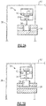
- FIG 2A schematically shows a solenoid valve 54.
- a leakage path 56 extends from the interior of the housing 42 into gearbox 38.
- a solenoid piston 62 is associated with a coil 60.
- Spring 64 biases the piston 62 upwardly as shown in Figure 2A . In the position illustrated in Figure 2A , power is received by the coil 60 and the piston 58 is moved downwardly against the force of the spring 64, blocking flow through the passage 56.
- Figure 2B shows the solenoid in a nominal or open position when power is not supplied to the coil 60.
- the spring 64 now moves the piston 58 upwardly such that the flow path 56 is open, and pressure within the housing 42 will vent.
Landscapes
- Engineering & Computer Science (AREA)
- General Engineering & Computer Science (AREA)
- Mechanical Engineering (AREA)
- Power Engineering (AREA)
- Physics & Mathematics (AREA)
- Electromagnetism (AREA)
- Connection Of Motors, Electrical Generators, Mechanical Devices, And The Like (AREA)
- Motor Or Generator Cooling System (AREA)
Abstract
Description
- This application relates to an electrical generator wherein a vent valve is provided to vent the interior of a housing case at shutdown.
- Electric generators are known and typically include a shaft driven by a source of rotation to rotate a generator rotor adjacent to a generator stator. With this rotation, electricity is generated and used for any number of uses.
- One known electric generator is housed in a housing and a generator rotor shaft extends outwardly of the housing. A liftoff seal is provided to seal the location where the shaft leaves the housing. As known, liftoff seals can gradually build up internal case pressure of the generator on subsequent start-stop cycles.
- It is also known to provide a pressure relief valve on the housing case to allow venting of the interior of the housing case should a pressure become undesirably high. However, in the past, the relief valves have opened an undesirably high number of times under some applications due to the pressure build up from the lift off seal.
- When the relief valve opens during operation of the electrical generator, it is possible for lubricant captured within the housing to flow outwardly of the housing.
- This is, of course, undesirable because with several cycles, eventually the generator could become low in oil before the normal service interval.
- An electric generator has a rotor shaft to be driven to rotate with a generator rotor. A generator stator is positioned adjacent the generator rotor. A housing surrounds the generator rotor and the generator stator. The generator rotor shaft extends outwardly of the housing. A seal seals a location where the rotor shaft extends outwardly of the housing. A vent valve is configured to vent of the interior of the housing when the rotor shaft is not rotating. An electrical assembly is also disclosed.
- An electrical assembly is also disclosed.
- These and other features may be best understood from the following drawings and specification.
-
-
Figure 1 schematically shows an electric generator and its associated housing. -
Figure 2A shows a solenoid valve in a blocked position. -
Figure 2B shows a solenoid valve in an open position. -
Figure 1 shows anelectric generator assembly 20. As known, the generator generates electricity for a use 22, shown schematically. In one application, this generator is a permanent magnet generator and the use 22 may be for various uses of electricity on an aircraft. - However, it should be understood that other types of generators besides permanent magnet generators and other uses besides aircraft applications may benefit from the teachings of this disclosure.
-
Generator stator coils 71 are positioned outwardly of apermanent magnet rotor 28. Thestator 71 androtor 28 are in operable communication to generate electricity. Thepermanent magnet rotor 28 rotates with agenerator shaft 30. A shaft 32 extends outwardly of ahousing 38 and to a source ofrotation 34. In one application, the source ofrotation 34 may be a gas turbine engine, such as found on aircraft engines. Again, other sources of rotation may be utilized. - A
gear connection 36 is shown schematically. As understood, thegearbox housing 38 may house a number of gears such that a change of speed between the input shaft 32 and thegenerator shaft 30 can occur. - A
drain 40 drains leaked lubricant fromhousing 38 to a central collection point or overboard. - A casing or
housing 42 surrounds the generator and geared speed trimming device (if applicable). Anominal oil level 43 is shown. - A
pressure relief valve 44 is positioned on thehousing 42, as known. - A
liftoff seal 46 is shown sealing a location where theshaft 30 leaves thehousing 42. As mentioned above, theliftoff seal 46 is intended to pump air across the seal during operation. The amount of air being pumped is very small, but over time can build up the case pressure to the point when thepressure relief valve 44 could open and discharge oil and spill out thedrain 40. - The
seal 46 may be two parts. Part 47A rotates withshaft 30. Part 47B is mounted inhousing 42. Part 47B does not rotate and is spring loaded to make contact withpart 46A. - However, applicant has found that the
liftoff seals 46 do not always allow the pressure to move down when the machine is not rotating. Instead, the pressure may hold when the machine is not rotation and may move up incrementally with each start/stop cycle. Thus, the pressure within thehousing 42 can become undesirably high. - This can lead to nuisance openings of the
pressure relief valve 44, which is undesirable as lubricant may leak outwardly. As such, avent valve 54, separate from the seal, is provided. - The vent valve, in one embodiment, is a solenoid actuated
valve 54 provided to ensure the pressure within thehousing 42 will move fully downwardly at shutdown. The solenoid actuatedvalve 54 may be located above the static oil level (level of oil in the machine when not rotating). The solenoid actuatedvalve 54 may also be located as close as possible to the highest elevation within the machine and oriented to vent between the gearbox pad and generator. As shown, arectifier 48 receives electric energy from asolenoid generator coil 52. Therectifier 48 converts AC power from the Permanent Magnet Generator (PMG) to DC power that the solenoid coils can use.Generator coil 52 is associated with apermanent magnet 50. Therectifier 48 supplies power to the solenoid actuatedvalve 54. - An
exciter stator 72 is positioned outwardly of anexciter rotor 73, and provides an exciter function, as is generally known. Asupplemental stator 26 may also be associated withpermanent magnet 50. Thisstator coil 26 may generate electricity to be used byauxiliary components 27, such as a general control unit. - Thus, when
shaft 30 rotates,magnet 50 rotates. Then, once the rotating hardware reaches a desired speed, the PMG is designed to supply sufficient power to actuate thesolenoid valve 54 and will close. - As can be appreciated from
Figure 1 , therectifier 48 is positioned under thenominal oil level 43. Thus, the oil level will cool the rectifier assembly. - When the generator is not rotating, electricity will not be generated between the
magnet 50 andcoil 52. The solenoid will then be de-energized and will move to its nominal open position. In the nominal open position, the solenoid allows air within thehousing 42 to vent into thegearbox housing 38 lowering the pressure within thehousing 42. -
Figure 2A schematically shows asolenoid valve 54. As shown, aleakage path 56 extends from the interior of thehousing 42 intogearbox 38. Asolenoid piston 62 is associated with acoil 60.Spring 64 biases thepiston 62 upwardly as shown inFigure 2A . In the position illustrated inFigure 2A , power is received by thecoil 60 and thepiston 58 is moved downwardly against the force of thespring 64, blocking flow through thepassage 56. -
Figure 2B shows the solenoid in a nominal or open position when power is not supplied to thecoil 60. Thespring 64 now moves thepiston 58 upwardly such that theflow path 56 is open, and pressure within thehousing 42 will vent. - As can be understood, when the
electrical generator 20 is being driven to rotate, power will be generated betweenmagnet 50 andcoil 52. The power passes through therectifier assembly 48 and powering thesolenoid 54. Prior to the beginning of this rotation, the solenoid will be in theFigure 2B position and the interior of thehousing 42 will be vented. However, once the electricity generated by the rotation of therotor shaft 30 builds up, power will be supplied to thesolenoid 54 and it will move to theFigure 2A position. The casing will no longer be vented. The advantage of closing the case during operation is that oil will not leak out through an open hole, case pressure will build up slightly and increase the efficiency of any pumps that are internal on the machine. - Although an embodiment of this invention has been disclosed, a worker of ordinary skill in this art would recognize that certain modifications would come within the scope of this invention. For that reason, the following claims should be studied to determine the true scope and content of this invention.
Claims (15)
- An electric generator comprising:a rotor shaft (30) to be driven to rotate with a rotor (28);a stator (71) in operable communication with said rotor (28);a housing (42) surrounding said rotor (28) and said stator (71);said rotor shaft (30) extending outwardly of said housing (42), and a seal (46) sealing a location where said rotor shaft (30) extends outwardly of said housing (42); anda vent valve (54), separate from said seal (46), and configured for allowing venting of the interior of said housing (42) when said rotor shaft (30) is not rotating.
- The electric generator as set forth in claim 1, wherein said vent valve (54) is a solenoid actuated valve biased to a vent position and driven to a non-venting position after said rotor shaft begins rotation.
- The electric generator as set forth in claim 2, wherein said rotor (28) and said stator (71) are configured to generate power to be supplied to said vent valve (54) to move said vent valve (54) from said vent position to said non-venting position when said rotor shaft (30) is driven to rotate.
- The electric generator as set forth in claim 3, wherein said stator (71) and said rotor (28) are separate from a main rotor and a main stator which generate electricity, and preferably
wherein said main rotor includes permanent magnets such that the electrical generator is a permanent magnet generator. - The electric generator as set forth in claim 3, wherein an electric line connects said stator (71) to said vent valve (54), and includes a rectifier for converting AC power to DC power, and preferably wherein said housing (42) includes a nominal oil level and said rectifier is positioned beneath said nominal oil level to provide cooling for said rectifier.
- The electric generator as set forth in claim 2, wherein said rotor (28) and said stator (71) are configured to generate power to be supplied to said vent valve (54) to move said vent valve from said vent position to said blocking position when said rotor shaft (30) is driven to rotate, an electric line connects said stator (71) to said vent valve(54), and includes a rectifier, said housing (42) includes a nominal oil level and said rectifier is positioned beneath said nominal oil level to provide cooling for said rectifier, said seal (46) is a liftoff seal, said rotor shaft (30) extends outwardly of said housing into a gearbox and said vent valve (54) venting said interior of said housing into an interior of said gearbox.
- The electric generator as set forth in any preceding claim, wherein said rotor shaft (30) extends outwardly of said housing (42) into a gearbox and said vent valve (54) vents said interior of said housing (42) into an interior of said gearbox.
- The electric generator as set forth in any preceding claim, wherein a pressure relief valve (44) opens to vent the interior of said housing (42) should a pressure within the interior of said housing (42) exceed a selected value.
- An assembly comprising:a gas turbine engine driving an output shaft, said output shaft extending to drive an electric generator, and said electric generator is configured to generate electricity for a use on an aircraft;said electric generator including a rotor shaft (30) coupled to be driven by said output shaft, and said rotor shaft (30) to be driven to rotate with a rotor(28);a stator (71) in operable communication with said rotor (28);a housing (42) surrounding said rotor (28) and said stator (71);said rotor shaft (30) extending outwardly of said housing (42), and a seal (46) sealing a location where said rotor shaft (30) extends outwardly of said housing (42); anda vent valve (54), separate from said seal (46), and configured for allowing venting of the interior of said housing (42) when said rotor shaft (30) is not rotating.
- The assembly as set forth in claim 9, wherein said vent valve (54) is a solenoid valve biased to a vent position and driven to a blocking position after said rotor shaft (30) begins rotation.
- The assembly as set forth in claim 10, wherein said rotor (28) and said stator (71) are configured to generate power to be supplied to said vent valve (54) to move said vent valve (54) from said vent position to said blocking position when said rotor shaft (30) is driven to rotate.
- The assembly as set forth in claim 11, wherein said stator (71) and said rotor (28) are separate from a main rotor and a main stator which generate electricity, and preferably
wherein said main rotor includes permanent magnets such that electrical generator is a permanent magnet generator. - The assembly as set forth in claim 11, wherein an electric line connecting said stator (71) to said vent valve (54) includes a rectifier, and preferably wherein said housing (42) includes a nominal oil level and said rectifier is positioned beneath said nominal oil level to provide cooling for said rectifier.
- The assembly as set forth in claim 11, wherein said rotor shaft (30) extends outwardly of said housing (42) into a gearbox and said vent valve (54) venting said interior of said housing into an interior of said gearbox; and/or wherein a pressure relief valve (44) opens to vent the interior of said housing (42) should a pressure within the interior of said housing (42) exceed a predetermined limit.
- The assembly as set forth in any preceding claim, wherein said rotor (28) and said stator (71) are configured to generate power to be supplied to said vent valve (54) to move said vent valve (54) from said vent position to said blocking position when said rotor shaft (30) is driven to rotate, an electric line connects said stator (71) to said vent valve (54), and includes a rectifier, said housing (42) includes a nominal oil level and said rectifier is positioned beneath said nominal oil level to provide cooling for said rectifier, said seal (46) is a liftoff seal, said rotor shaft (30) extends outwardly of said housing (42) into a gearbox and said vent valve (54) venting said interior of said housing (42) into an interior of said gearbox.
Applications Claiming Priority (1)
| Application Number | Priority Date | Filing Date | Title |
|---|---|---|---|
| US15/649,761 US10704704B2 (en) | 2017-07-14 | 2017-07-14 | Permanent magnet generator case vent valve |
Publications (2)
| Publication Number | Publication Date |
|---|---|
| EP3429066A1 true EP3429066A1 (en) | 2019-01-16 |
| EP3429066B1 EP3429066B1 (en) | 2021-07-07 |
Family
ID=62975909
Family Applications (1)
| Application Number | Title | Priority Date | Filing Date |
|---|---|---|---|
| EP18183639.6A Active EP3429066B1 (en) | 2017-07-14 | 2018-07-16 | Permanent magnet generator case vent valve |
Country Status (2)
| Country | Link |
|---|---|
| US (1) | US10704704B2 (en) |
| EP (1) | EP3429066B1 (en) |
Families Citing this family (4)
| Publication number | Priority date | Publication date | Assignee | Title |
|---|---|---|---|---|
| CN112747136B (en) * | 2020-12-31 | 2025-03-21 | 周卫华 | A chemical protection, gas filtering and ventilation switching valve |
| CN115476460B (en) * | 2022-08-03 | 2026-04-24 | 广东仕诚塑料机械有限公司 | Casting roller mounting structure |
| DE102022004623B3 (en) | 2022-12-09 | 2024-02-29 | Mercedes-Benz Group AG | Drive device for a motor vehicle and method for operating a drive device |
| CN118508654B (en) * | 2024-07-17 | 2024-10-11 | 丽水方德智驱应用技术研究院有限公司 | Active pressure-adaptive driving motor capable of avoiding condensation and rust phenomena |
Citations (5)
| Publication number | Priority date | Publication date | Assignee | Title |
|---|---|---|---|---|
| DE9418307U1 (en) * | 1994-11-15 | 1996-03-14 | Energieversorgung Leverkusen GmbH, 51371 Leverkusen | Gas expansion machine |
| JP2008228378A (en) * | 2007-03-08 | 2008-09-25 | Toyota Motor Corp | Motor insulation protection device and vehicle having the same |
| EP2211445A2 (en) * | 2009-01-27 | 2010-07-28 | General Electric Company | Automated seal oil by-pass system for hydrogen cooled generators |
| US20110309780A1 (en) * | 2010-06-17 | 2011-12-22 | General Electric Company | Seal leakage and seal oil contamination detection in generator |
| US20130046426A1 (en) * | 2010-05-18 | 2013-02-21 | Hiroyuki Tsukashima | Vehicle control system |
Family Cites Families (6)
| Publication number | Priority date | Publication date | Assignee | Title |
|---|---|---|---|---|
| FR2140926A5 (en) | 1971-06-09 | 1973-01-19 | Citroen Sa | |
| US4883995A (en) * | 1988-12-30 | 1989-11-28 | General Electric Company | Automatic oil draining system for generators |
| US6844707B1 (en) | 2003-12-30 | 2005-01-18 | Pacific Scientific/Electro Kinetics Division | AC/DC brushless starter-generator |
| US8302390B2 (en) | 2004-09-28 | 2012-11-06 | Continental Automotive Systems Us, Inc. | Turbo control valve utilizing a permanent magnet |
| US7651069B2 (en) | 2006-05-26 | 2010-01-26 | General Electric Company | Electromagnetic actuators |
| US9431877B2 (en) * | 2014-12-03 | 2016-08-30 | The Boeing Company | Concentric ring generators |
-
2017
- 2017-07-14 US US15/649,761 patent/US10704704B2/en active Active
-
2018
- 2018-07-16 EP EP18183639.6A patent/EP3429066B1/en active Active
Patent Citations (5)
| Publication number | Priority date | Publication date | Assignee | Title |
|---|---|---|---|---|
| DE9418307U1 (en) * | 1994-11-15 | 1996-03-14 | Energieversorgung Leverkusen GmbH, 51371 Leverkusen | Gas expansion machine |
| JP2008228378A (en) * | 2007-03-08 | 2008-09-25 | Toyota Motor Corp | Motor insulation protection device and vehicle having the same |
| EP2211445A2 (en) * | 2009-01-27 | 2010-07-28 | General Electric Company | Automated seal oil by-pass system for hydrogen cooled generators |
| US20130046426A1 (en) * | 2010-05-18 | 2013-02-21 | Hiroyuki Tsukashima | Vehicle control system |
| US20110309780A1 (en) * | 2010-06-17 | 2011-12-22 | General Electric Company | Seal leakage and seal oil contamination detection in generator |
Also Published As
| Publication number | Publication date |
|---|---|
| EP3429066B1 (en) | 2021-07-07 |
| US20190017620A1 (en) | 2019-01-17 |
| US10704704B2 (en) | 2020-07-07 |
Similar Documents
| Publication | Publication Date | Title |
|---|---|---|
| EP3429066B1 (en) | Permanent magnet generator case vent valve | |
| US20100283338A1 (en) | Oil filter bypass valve assembly for a generator | |
| CN105952639B (en) | Compressor device and use of such a compressor device | |
| US8485222B2 (en) | Systems and methods for preventing oil migration | |
| JP4156261B2 (en) | Gas turbine engine operating method, oil sump pressure reducing device, and gas turbine engine equipped with the device | |
| RU2645778C2 (en) | Turbomachine lubrication system with antisiphon valve for autorotation | |
| US8991344B2 (en) | Filling of a volume accumulator in a camshaft adjuster | |
| JP2009528468A (en) | Incorporation of starter / generator module in gas turbine transmission housing | |
| EP2667035A2 (en) | Temperature control system for a machine and methods of operating same | |
| US20090235632A1 (en) | Gas-turbine bearing oil system with improved oil return arrangement | |
| US20150184659A1 (en) | Drive unit for a submersible oil pump, a pump | |
| US20060244263A1 (en) | Electric motor starting device | |
| JP6185572B2 (en) | Lubricating method for wind turbine gearbox | |
| US20140250914A1 (en) | Starter Motor Shared Lubrication System | |
| EP2891795B1 (en) | Hydraulic transmission, wind turbine power generating apparatus, and operation control method | |
| US12535130B2 (en) | Gearbox arrangement providing partial vacuum within a gearbox device as well as method of efficiently providing and maintaining partial vacuum and use | |
| CN102477996B (en) | Pump | |
| RU2535518C1 (en) | Oil system of power gas turbine unit | |
| JP2008508480A (en) | Linking | |
| RU2731826C1 (en) | Oil system of gas turbine power plant | |
| CN107725198A (en) | Gas turbine Pneumatic drive system | |
| RU27170U1 (en) | FLOW DEAERATION DEVICE FOR VERTICAL CENTRIFUGAL PUMP TURBO UNIT CONTROL SYSTEM | |
| JPH07259783A (en) | Self-control bypass valve | |
| KR20020024648A (en) | Apparatus and method for providing gas turbine engine with lubricant | |
| NZ627526B2 (en) | Compressor device as well as the use of such a compressor device |
Legal Events
| Date | Code | Title | Description |
|---|---|---|---|
| PUAI | Public reference made under article 153(3) epc to a published international application that has entered the european phase |
Free format text: ORIGINAL CODE: 0009012 |
|
| STAA | Information on the status of an ep patent application or granted ep patent |
Free format text: STATUS: THE APPLICATION HAS BEEN PUBLISHED |
|
| AK | Designated contracting states |
Kind code of ref document: A1 Designated state(s): AL AT BE BG CH CY CZ DE DK EE ES FI FR GB GR HR HU IE IS IT LI LT LU LV MC MK MT NL NO PL PT RO RS SE SI SK SM TR |
|
| AX | Request for extension of the european patent |
Extension state: BA ME |
|
| STAA | Information on the status of an ep patent application or granted ep patent |
Free format text: STATUS: REQUEST FOR EXAMINATION WAS MADE |
|
| 17P | Request for examination filed |
Effective date: 20190716 |
|
| RBV | Designated contracting states (corrected) |
Designated state(s): AL AT BE BG CH CY CZ DE DK EE ES FI FR GB GR HR HU IE IS IT LI LT LU LV MC MK MT NL NO PL PT RO RS SE SI SK SM TR |
|
| GRAP | Despatch of communication of intention to grant a patent |
Free format text: ORIGINAL CODE: EPIDOSNIGR1 |
|
| STAA | Information on the status of an ep patent application or granted ep patent |
Free format text: STATUS: GRANT OF PATENT IS INTENDED |
|
| INTG | Intention to grant announced |
Effective date: 20210202 |
|
| GRAS | Grant fee paid |
Free format text: ORIGINAL CODE: EPIDOSNIGR3 |
|
| GRAA | (expected) grant |
Free format text: ORIGINAL CODE: 0009210 |
|
| STAA | Information on the status of an ep patent application or granted ep patent |
Free format text: STATUS: THE PATENT HAS BEEN GRANTED |
|
| AK | Designated contracting states |
Kind code of ref document: B1 Designated state(s): AL AT BE BG CH CY CZ DE DK EE ES FI FR GB GR HR HU IE IS IT LI LT LU LV MC MK MT NL NO PL PT RO RS SE SI SK SM TR |
|
| REG | Reference to a national code |
Ref country code: GB Ref legal event code: FG4D |
|
| REG | Reference to a national code |
Ref country code: AT Ref legal event code: REF Ref document number: 1409528 Country of ref document: AT Kind code of ref document: T Effective date: 20210715 |
|
| REG | Reference to a national code |
Ref country code: DE Ref legal event code: R096 Ref document number: 602018019586 Country of ref document: DE |
|
| REG | Reference to a national code |
Ref country code: IE Ref legal event code: FG4D |
|
| REG | Reference to a national code |
Ref country code: LT Ref legal event code: MG9D |
|
| REG | Reference to a national code |
Ref country code: NL Ref legal event code: MP Effective date: 20210707 |
|
| REG | Reference to a national code |
Ref country code: AT Ref legal event code: MK05 Ref document number: 1409528 Country of ref document: AT Kind code of ref document: T Effective date: 20210707 |
|
| PG25 | Lapsed in a contracting state [announced via postgrant information from national office to epo] |
Ref country code: PT Free format text: LAPSE BECAUSE OF FAILURE TO SUBMIT A TRANSLATION OF THE DESCRIPTION OR TO PAY THE FEE WITHIN THE PRESCRIBED TIME-LIMIT Effective date: 20211108 Ref country code: NL Free format text: LAPSE BECAUSE OF FAILURE TO SUBMIT A TRANSLATION OF THE DESCRIPTION OR TO PAY THE FEE WITHIN THE PRESCRIBED TIME-LIMIT Effective date: 20210707 Ref country code: NO Free format text: LAPSE BECAUSE OF FAILURE TO SUBMIT A TRANSLATION OF THE DESCRIPTION OR TO PAY THE FEE WITHIN THE PRESCRIBED TIME-LIMIT Effective date: 20211007 Ref country code: LT Free format text: LAPSE BECAUSE OF FAILURE TO SUBMIT A TRANSLATION OF THE DESCRIPTION OR TO PAY THE FEE WITHIN THE PRESCRIBED TIME-LIMIT Effective date: 20210707 Ref country code: AT Free format text: LAPSE BECAUSE OF FAILURE TO SUBMIT A TRANSLATION OF THE DESCRIPTION OR TO PAY THE FEE WITHIN THE PRESCRIBED TIME-LIMIT Effective date: 20210707 Ref country code: BG Free format text: LAPSE BECAUSE OF FAILURE TO SUBMIT A TRANSLATION OF THE DESCRIPTION OR TO PAY THE FEE WITHIN THE PRESCRIBED TIME-LIMIT Effective date: 20211007 Ref country code: SE Free format text: LAPSE BECAUSE OF FAILURE TO SUBMIT A TRANSLATION OF THE DESCRIPTION OR TO PAY THE FEE WITHIN THE PRESCRIBED TIME-LIMIT Effective date: 20210707 Ref country code: RS Free format text: LAPSE BECAUSE OF FAILURE TO SUBMIT A TRANSLATION OF THE DESCRIPTION OR TO PAY THE FEE WITHIN THE PRESCRIBED TIME-LIMIT Effective date: 20210707 Ref country code: HR Free format text: LAPSE BECAUSE OF FAILURE TO SUBMIT A TRANSLATION OF THE DESCRIPTION OR TO PAY THE FEE WITHIN THE PRESCRIBED TIME-LIMIT Effective date: 20210707 Ref country code: ES Free format text: LAPSE BECAUSE OF FAILURE TO SUBMIT A TRANSLATION OF THE DESCRIPTION OR TO PAY THE FEE WITHIN THE PRESCRIBED TIME-LIMIT Effective date: 20210707 Ref country code: FI Free format text: LAPSE BECAUSE OF FAILURE TO SUBMIT A TRANSLATION OF THE DESCRIPTION OR TO PAY THE FEE WITHIN THE PRESCRIBED TIME-LIMIT Effective date: 20210707 |
|
| PG25 | Lapsed in a contracting state [announced via postgrant information from national office to epo] |
Ref country code: PL Free format text: LAPSE BECAUSE OF FAILURE TO SUBMIT A TRANSLATION OF THE DESCRIPTION OR TO PAY THE FEE WITHIN THE PRESCRIBED TIME-LIMIT Effective date: 20210707 Ref country code: LV Free format text: LAPSE BECAUSE OF FAILURE TO SUBMIT A TRANSLATION OF THE DESCRIPTION OR TO PAY THE FEE WITHIN THE PRESCRIBED TIME-LIMIT Effective date: 20210707 Ref country code: GR Free format text: LAPSE BECAUSE OF FAILURE TO SUBMIT A TRANSLATION OF THE DESCRIPTION OR TO PAY THE FEE WITHIN THE PRESCRIBED TIME-LIMIT Effective date: 20211008 |
|
| REG | Reference to a national code |
Ref country code: CH Ref legal event code: PL |
|
| REG | Reference to a national code |
Ref country code: BE Ref legal event code: MM Effective date: 20210731 |
|
| REG | Reference to a national code |
Ref country code: DE Ref legal event code: R097 Ref document number: 602018019586 Country of ref document: DE |
|
| PG25 | Lapsed in a contracting state [announced via postgrant information from national office to epo] |
Ref country code: LI Free format text: LAPSE BECAUSE OF NON-PAYMENT OF DUE FEES Effective date: 20210731 Ref country code: DK Free format text: LAPSE BECAUSE OF FAILURE TO SUBMIT A TRANSLATION OF THE DESCRIPTION OR TO PAY THE FEE WITHIN THE PRESCRIBED TIME-LIMIT Effective date: 20210707 Ref country code: CH Free format text: LAPSE BECAUSE OF NON-PAYMENT OF DUE FEES Effective date: 20210731 |
|
| PLBE | No opposition filed within time limit |
Free format text: ORIGINAL CODE: 0009261 |
|
| STAA | Information on the status of an ep patent application or granted ep patent |
Free format text: STATUS: NO OPPOSITION FILED WITHIN TIME LIMIT |
|
| PG25 | Lapsed in a contracting state [announced via postgrant information from national office to epo] |
Ref country code: SM Free format text: LAPSE BECAUSE OF FAILURE TO SUBMIT A TRANSLATION OF THE DESCRIPTION OR TO PAY THE FEE WITHIN THE PRESCRIBED TIME-LIMIT Effective date: 20210707 Ref country code: SK Free format text: LAPSE BECAUSE OF FAILURE TO SUBMIT A TRANSLATION OF THE DESCRIPTION OR TO PAY THE FEE WITHIN THE PRESCRIBED TIME-LIMIT Effective date: 20210707 Ref country code: RO Free format text: LAPSE BECAUSE OF FAILURE TO SUBMIT A TRANSLATION OF THE DESCRIPTION OR TO PAY THE FEE WITHIN THE PRESCRIBED TIME-LIMIT Effective date: 20210707 Ref country code: MC Free format text: LAPSE BECAUSE OF FAILURE TO SUBMIT A TRANSLATION OF THE DESCRIPTION OR TO PAY THE FEE WITHIN THE PRESCRIBED TIME-LIMIT Effective date: 20210707 Ref country code: LU Free format text: LAPSE BECAUSE OF NON-PAYMENT OF DUE FEES Effective date: 20210716 Ref country code: EE Free format text: LAPSE BECAUSE OF FAILURE TO SUBMIT A TRANSLATION OF THE DESCRIPTION OR TO PAY THE FEE WITHIN THE PRESCRIBED TIME-LIMIT Effective date: 20210707 Ref country code: CZ Free format text: LAPSE BECAUSE OF FAILURE TO SUBMIT A TRANSLATION OF THE DESCRIPTION OR TO PAY THE FEE WITHIN THE PRESCRIBED TIME-LIMIT Effective date: 20210707 Ref country code: AL Free format text: LAPSE BECAUSE OF FAILURE TO SUBMIT A TRANSLATION OF THE DESCRIPTION OR TO PAY THE FEE WITHIN THE PRESCRIBED TIME-LIMIT Effective date: 20210707 |
|
| 26N | No opposition filed |
Effective date: 20220408 |
|
| PG25 | Lapsed in a contracting state [announced via postgrant information from national office to epo] |
Ref country code: IT Free format text: LAPSE BECAUSE OF FAILURE TO SUBMIT A TRANSLATION OF THE DESCRIPTION OR TO PAY THE FEE WITHIN THE PRESCRIBED TIME-LIMIT Effective date: 20210707 Ref country code: IE Free format text: LAPSE BECAUSE OF NON-PAYMENT OF DUE FEES Effective date: 20210716 Ref country code: BE Free format text: LAPSE BECAUSE OF NON-PAYMENT OF DUE FEES Effective date: 20210731 |
|
| P01 | Opt-out of the competence of the unified patent court (upc) registered |
Effective date: 20230522 |
|
| PG25 | Lapsed in a contracting state [announced via postgrant information from national office to epo] |
Ref country code: CY Free format text: LAPSE BECAUSE OF FAILURE TO SUBMIT A TRANSLATION OF THE DESCRIPTION OR TO PAY THE FEE WITHIN THE PRESCRIBED TIME-LIMIT Effective date: 20210707 |
|
| PG25 | Lapsed in a contracting state [announced via postgrant information from national office to epo] |
Ref country code: HU Free format text: LAPSE BECAUSE OF FAILURE TO SUBMIT A TRANSLATION OF THE DESCRIPTION OR TO PAY THE FEE WITHIN THE PRESCRIBED TIME-LIMIT; INVALID AB INITIO Effective date: 20180716 |
|
| PG25 | Lapsed in a contracting state [announced via postgrant information from national office to epo] |
Ref country code: MK Free format text: LAPSE BECAUSE OF FAILURE TO SUBMIT A TRANSLATION OF THE DESCRIPTION OR TO PAY THE FEE WITHIN THE PRESCRIBED TIME-LIMIT Effective date: 20210707 |
|
| PG25 | Lapsed in a contracting state [announced via postgrant information from national office to epo] |
Ref country code: TR Free format text: LAPSE BECAUSE OF FAILURE TO SUBMIT A TRANSLATION OF THE DESCRIPTION OR TO PAY THE FEE WITHIN THE PRESCRIBED TIME-LIMIT Effective date: 20210707 |
|
| PG25 | Lapsed in a contracting state [announced via postgrant information from national office to epo] |
Ref country code: MT Free format text: LAPSE BECAUSE OF FAILURE TO SUBMIT A TRANSLATION OF THE DESCRIPTION OR TO PAY THE FEE WITHIN THE PRESCRIBED TIME-LIMIT Effective date: 20210707 |
|
| PGFP | Annual fee paid to national office [announced via postgrant information from national office to epo] |
Ref country code: GB Payment date: 20250619 Year of fee payment: 8 |
|
| PGFP | Annual fee paid to national office [announced via postgrant information from national office to epo] |
Ref country code: FR Payment date: 20250620 Year of fee payment: 8 |
|
| PGFP | Annual fee paid to national office [announced via postgrant information from national office to epo] |
Ref country code: DE Payment date: 20250620 Year of fee payment: 8 |