EP3429038A1 - Pulse laser device - Google Patents
Pulse laser device Download PDFInfo
- Publication number
- EP3429038A1 EP3429038A1 EP18181443.5A EP18181443A EP3429038A1 EP 3429038 A1 EP3429038 A1 EP 3429038A1 EP 18181443 A EP18181443 A EP 18181443A EP 3429038 A1 EP3429038 A1 EP 3429038A1
- Authority
- EP
- European Patent Office
- Prior art keywords
- fiber
- light
- pulse laser
- laser device
- linearly polarized
- Prior art date
- Legal status (The legal status is an assumption and is not a legal conclusion. Google has not performed a legal analysis and makes no representation as to the accuracy of the status listed.)
- Granted
Links
Images


Classifications
-
- H—ELECTRICITY
- H01—ELECTRIC ELEMENTS
- H01S—DEVICES USING THE PROCESS OF LIGHT AMPLIFICATION BY STIMULATED EMISSION OF RADIATION [LASER] TO AMPLIFY OR GENERATE LIGHT; DEVICES USING STIMULATED EMISSION OF ELECTROMAGNETIC RADIATION IN WAVE RANGES OTHER THAN OPTICAL
- H01S3/00—Lasers, i.e. devices using stimulated emission of electromagnetic radiation in the infrared, visible or ultraviolet wave range
- H01S3/10—Controlling the intensity, frequency, phase, polarisation or direction of the emitted radiation, e.g. switching, gating, modulating or demodulating
- H01S3/11—Mode locking; Q-switching; Other giant-pulse techniques, e.g. cavity dumping
- H01S3/1106—Mode locking
- H01S3/1112—Passive mode locking
- H01S3/1115—Passive mode locking using intracavity saturable absorbers
- H01S3/1118—Semiconductor saturable absorbers, e.g. semiconductor saturable absorber mirrors [SESAMs]; Solid-state saturable absorbers, e.g. carbon nanotube [CNT] based
-
- H—ELECTRICITY
- H01—ELECTRIC ELEMENTS
- H01S—DEVICES USING THE PROCESS OF LIGHT AMPLIFICATION BY STIMULATED EMISSION OF RADIATION [LASER] TO AMPLIFY OR GENERATE LIGHT; DEVICES USING STIMULATED EMISSION OF ELECTROMAGNETIC RADIATION IN WAVE RANGES OTHER THAN OPTICAL
- H01S3/00—Lasers, i.e. devices using stimulated emission of electromagnetic radiation in the infrared, visible or ultraviolet wave range
- H01S3/05—Construction or shape of optical resonators; Accommodation of active medium therein; Shape of active medium
- H01S3/06—Construction or shape of active medium
- H01S3/063—Waveguide lasers, i.e. whereby the dimensions of the waveguide are of the order of the light wavelength
- H01S3/067—Fibre lasers
- H01S3/06708—Constructional details of the fibre, e.g. compositions, cross-section, shape or tapering
- H01S3/06712—Polarising fibre; Polariser
-
- H—ELECTRICITY
- H01—ELECTRIC ELEMENTS
- H01S—DEVICES USING THE PROCESS OF LIGHT AMPLIFICATION BY STIMULATED EMISSION OF RADIATION [LASER] TO AMPLIFY OR GENERATE LIGHT; DEVICES USING STIMULATED EMISSION OF ELECTROMAGNETIC RADIATION IN WAVE RANGES OTHER THAN OPTICAL
- H01S3/00—Lasers, i.e. devices using stimulated emission of electromagnetic radiation in the infrared, visible or ultraviolet wave range
- H01S3/05—Construction or shape of optical resonators; Accommodation of active medium therein; Shape of active medium
- H01S3/06—Construction or shape of active medium
- H01S3/063—Waveguide lasers, i.e. whereby the dimensions of the waveguide are of the order of the light wavelength
- H01S3/067—Fibre lasers
- H01S3/06791—Fibre ring lasers
-
- H—ELECTRICITY
- H01—ELECTRIC ELEMENTS
- H01S—DEVICES USING THE PROCESS OF LIGHT AMPLIFICATION BY STIMULATED EMISSION OF RADIATION [LASER] TO AMPLIFY OR GENERATE LIGHT; DEVICES USING STIMULATED EMISSION OF ELECTROMAGNETIC RADIATION IN WAVE RANGES OTHER THAN OPTICAL
- H01S3/00—Lasers, i.e. devices using stimulated emission of electromagnetic radiation in the infrared, visible or ultraviolet wave range
- H01S3/05—Construction or shape of optical resonators; Accommodation of active medium therein; Shape of active medium
- H01S3/08—Construction or shape of optical resonators or components thereof
- H01S3/08054—Passive cavity elements acting on the polarization, e.g. a polarizer for branching or walk-off compensation
-
- H—ELECTRICITY
- H01—ELECTRIC ELEMENTS
- H01S—DEVICES USING THE PROCESS OF LIGHT AMPLIFICATION BY STIMULATED EMISSION OF RADIATION [LASER] TO AMPLIFY OR GENERATE LIGHT; DEVICES USING STIMULATED EMISSION OF ELECTROMAGNETIC RADIATION IN WAVE RANGES OTHER THAN OPTICAL
- H01S3/00—Lasers, i.e. devices using stimulated emission of electromagnetic radiation in the infrared, visible or ultraviolet wave range
- H01S3/10—Controlling the intensity, frequency, phase, polarisation or direction of the emitted radiation, e.g. switching, gating, modulating or demodulating
- H01S3/11—Mode locking; Q-switching; Other giant-pulse techniques, e.g. cavity dumping
- H01S3/1106—Mode locking
- H01S3/1112—Passive mode locking
-
- H—ELECTRICITY
- H01—ELECTRIC ELEMENTS
- H01S—DEVICES USING THE PROCESS OF LIGHT AMPLIFICATION BY STIMULATED EMISSION OF RADIATION [LASER] TO AMPLIFY OR GENERATE LIGHT; DEVICES USING STIMULATED EMISSION OF ELECTROMAGNETIC RADIATION IN WAVE RANGES OTHER THAN OPTICAL
- H01S5/00—Semiconductor lasers
- H01S5/50—Amplifier structures not provided for in groups H01S5/02 - H01S5/30
- H01S5/5009—Amplifier structures not provided for in groups H01S5/02 - H01S5/30 the arrangement being polarisation-insensitive
Definitions
- the technical field relates to a pulse laser device.
- Mode-locked ultra-short pulse fiber laser has many applications, such as micro machining, laser surgical operation, optical frequency measurement, etc.
- Nonlinear polarization rotation (NPR) has been used as an artificial saturable absorber in a fiber ring laser to start the mode-locking for many years.
- NPR mode-locked fiber ring laser requires the polarization of the laser to be elliptical at the input end of the fiber and nonlinear phase generated in the fiber makes the polarization ellipse rotate.
- non-polarization-maintaining (non-PM) single mode fiber is used.
- the refraction index of non-PM single mode fiber can be changed by environmental temperature or pressure variation, thus, the polarization state of the laser light in the laser resonator can be changed and mode-locking may fail. Therefore, an environmental stable mode-locked fiber laser is urgent for reliably operating the ultra-short pulse fiber laser.
- a pulse laser device with a ring laser resonator is introduced herein.
- the laser device includes a polarization maintaining (PM) fiber, a first quarter waveplate, and an optical isolator in the ring laser resonator.
- the PM fiber has a light input end and a light output end and is configured to guide a first linearly polarized light with a first phase along a fast axis of the PM fiber from the light input end and a second linearly polarized light with a second phase along a slow axis of the PM fiber from the input end.
- the first quarter waveplate is disposed at the light output end of the PM fiber and configured to convert the first and the second linearly polarized lights into left-handed and right-handed (or right-handed and left-handed) circularly polarized lights, respectively. Mode-locking is obtained by the nonlinear polarization rotation formed through the combination of the PM fiber and the first quarter waveplate.
- the optical isolator is configured to unidirectionally transmit a laser pulse in the ring laser resonator.
- the PM fiber has at least one 90-degree-cross-splicing position to eliminate delay between the first linearly polarized light and the second linearly polarized light.
- the PM fiber, the first quarter waveplate, and the optical isolator are on a light path of the ring laser resonator.
- FIG. 1 is a schematic view of a pulse laser device according to an exemplary embodiment.
- the laser device 100 with a ring laser resonator in this embodiment includes a polarization maintaining (PM) fiber 110, a first quarter waveplate 120, and an optical isolator 130 in the ring laser resonator.
- the PM fiber 110 includes a PM gain fiber section 112, which may be at least one of a section of Erbium, Ytterbium, Holmium, or Thulium-doped fiber and a Raman or Brillouin gain medium.
- the pulse laser device further includes a pump laser 140 and a wavelength-division multiplexer (WDM) 150, and the PM gain fiber section 112 is pumped by the pump laser 140 through the wavelength-division multiplexer 150.
- the pump laser 140 is, for example, a diode laser, a semiconductor laser, a solid state laser, a continuous wave fiber laser, or any other type of laser.
- the pump laser 140 emits a light having a wavelength of 980 nm, which is transmitted to the PM gain fiber section 112 through the WDM 150.
- the PM gain fiber section 112 absorbs the light having the wavelength of 980 nm, and generates a light having the wavelength of 1550 nm, for example.
- the PM fiber 110, the first quarter waveplate 120, the optical isolator 130, and the WDM 150 are on a light path of the ring laser resonator (i.e. the ring shown in FIG. 1 ), and the optical isolator 130 is configured to unidirectionally transmit the light having the wavelength of 1550 nm, and ensure a single direction of lasing.
- the optical isolator 130 makes the light having the wavelength of 1550 nm travel clockwise in FIG. 1 in the ring laser resonator.
- the PM fiber 110 has a light input end 111 and a light output end 113.
- a collimator 220 and a collimator 230 are respectively disposed on the light input end 111 and the light output end 113.
- the pulse laser device 100 in this embodiment further includes an output coupling device 160 disposed on the light path of the ring laser resonator.
- the output coupling device 160 includes at least one of a polarizing beam splitter (PBS) and a fiber coupler.
- PBS polarizing beam splitter
- the output coupling device 160 is a PBS
- the optical isolator 130 may be a polarization sensitive isolator or a polarization insensitive isolator.
- the optical isolator 130 is a polarization sensitive isolator if the output coupling device 160 is a fiber coupler and no PBS is used as an output coupling device, the optical isolator 130 is a polarization sensitive isolator.
- the light having the wavelength 1550 nm After the light having the wavelength 1550 nm passes through the coupling device 160 and the optical isolator 130, the light having the wavelength 1550 nm has an electric field P tilted with respect to the fast axis X1 (parallel to the y-direction in FIG. 2A ) and the slow axis X2 (parallel to the x-direction in FIG. 2A ) of the PM fiber 110.
- the x-direction is perpendicular to the y-direction.
- the light having the wavelength of 1550 nm and having the electric field P of linear polarization may be deemed a combination of a first linearly polarized light having an electric field PI parallel to the fast axis X1 and a second linearly polarized light having an electric field P2 parallel to the slow axis X2.
- the optical isolator 130 is configured to unidirectionally transmit a laser pulse in the reasonator.
- the light having the wavelength of 980 nm and the light having the wavelength of 1550 nm are taken as an example, but the disclosure is not limited thereto.
- it may provide a pumping light with a wavelength other than 980 nm, and by adopting another type of gain medium, it may generate a light with a wavelength other than 1550 nm.
- the PM fiber 110 is configured to guide the first linearly polarized light with a first phase along the fast axis X1 of the PM fiber 110 from the light input end 111 and a second linearly polarized light with a second phase along a slow axis X2 of the PM fiber 110 from the input end 111.
- the first phase is the same as the second phase.
- the first phase is different from the second phase.
- the first quarter waveplate 120 is disposed at the light output end 113 of the PM fiber 110 and configured to convert the first and the second linearly polarized lights into left-handed and right-handed (or right-handed and left-handed) circularly polarized lights, respectively.
- a linear phase difference and a nonlinear phase difference between the two pulses propagating along the fast axis X1 and the slow axis X2 become the phase difference between the two circularly polarized lights after the first quarter waveplate 120.
- the amplitude of the first linearly polarized light is different from that of the second linearly polarized light, so that the amplitude of the left-handed circularly polarized light is different from that of the right-handed circularly polarized light.
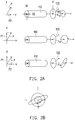
- the left-handed circularly polarized light and the right-handed circularly polarized light combine into an elliptically polarized light with a laser field polarization ellipse having the principal axis angle dependent on the linear and nonlinear phase difference, as shown in FIGs. 2A and 2B .
- the first quarter waveplate 120 has an optical axis 122 tilted with respect to the fast axis X1 and the slow axis X2 of the PM fiber 110 by 45 degrees.
- the PM fiber 110 has at least one 90-degree-cross-splicing position C to eliminate the delay between the first linearly polarized light and the second linearly polarized light.
- the PM fiber 110 includes a section 114 and a section 116 spliced together at the 90-degree-cross-splicing position C, and the fast axis of the section 114 is aligned and parallel with the slow axis of the section 116, and the slow axis of the section 114 is aligned and parallel with the fast axis of the section 116.
- every different kind of fiber in the laser cavity has at least one 90-degree-cross-splicing to compensate the delay of the pulses propagating along the slow and fast axis in that kind of fiber.
- the laser cavity has two different kinds of fibers, one is a gain fiber and the other is a passive fiber, then the gain fiber has at least one 90-degree-cross-splicing to compensate the delay caused by the gain fiber, and the other passive fiber has at least one 90-degree-cross-splicing to compensate the delay caused by the passive fiber.
- at least one 90-degree-cross-splicing can be applied to the middle or to the positions of length ratio of 1:2:1 of that kind of fiber.
- the pulse laser device 100 is a mode-locked fiber ring laser with all PM fiber 110 based on nonlinear polarization rotation (NPR) mechanism.
- the NPR mechanism happens from the combination of inputting linearly polarized light into the PM fiber 110 with the electric field P tilted with respect to the slow axis X2 and the fast axis X1 of the PM fiber 110 and a first quarter waveplate 120 mounted after the PM fiber 110 with the optical axis 122 tilted 45° from the fast axis X1 and the slow axis X2 of the PM fiber 110.
- the first quarter waveplate 120 transforms the two linearly polarized lights from the fast and the slow axes X1 and X2 into left- and right-handed circularly polarized lights respectively.
- the superposition of the two circularly polarized is elliptically polarized light with the angle of the principal axis depending on the nonlinear phase difference of the two light fields obtained in the fast and slow axes X1 and X2 of the PM fiber.
- the laser field polarization ellipse is formed and rotates after the combination of the PM fiber 110 and the first quarter waveplate 120, not along the fiber.
- the PM fiber 110 maintains the polarizations of the two linearly polarized lights along the fast and slow axes X1 and X2 to reduce the effect of environmental variations, e.g. temperature and pressure variations. As a result, an environmental stable mode-locked fiber laser, i.e. the pulse laser device 100, is achieved.
- environmental variations e.g. temperature and pressure variations.
- the principal axis L of the laser field polarization ellipse after the first quarter waveplate 120 rotates as shown in FIG. 3 , but the shape of the ellipse is not changed.
- the output coupling device 160 i.e. a PBS
- an additional fiber coupler may also be spliced in the ring laser resonator to output another pulse laser beam.
- the pulse laser device 100 further includes a polarization controlling device 170 disposed on the light path of the ring laser resonator between the first quarter waveplate 120 and the optical isolator 130.
- the polarization controlling device 170 may include a half waveplate 172, a second quarter waveplate 174, or a combination thereof.
- the polarization controlling device 170 includes the half waveplate 172 and the second quarter waveplate 174.
- the optical axes of the half waveplate 172 and the second quarter waveplate 174 may be rotated to appropriate directions to allow high intensity light to pass through the output coupling device 160 (i.e. the PBS), compensate a residual linear phase difference, and facilitate the generation of mode-locking.
- the half waveplate 172 is disposed between the first quarter waveplate 120 and the second quarter waveplate 174.
- the position of the half waveplate 172 and the position of the second quarter waveplate 174 may be interchanged; that is, the second quarter waveplate 174 may be disposed between the first quarter waveplate 120 and the half waveplate 172.
- the polarization controlling device 170 can be installed before the first quarter waveplate 120, while both of them are rotatable to realize the transformation of the two linearly polarized lights into circularly polarized lights and also functioning the rotation of the principal axis of the superposed polarization ellipse.
- At least one of a half waveplate and an other retardation waveplate i.e. a waveplate having retardation different from half a wavelength, i.e., different from the retardation of a half waveplate
- a quarter waveplate may be disposed on the light path of the ring laser resonator and at the light input end 111 of the PM fiber 110 to adjust the light field amplitude inputted to the fast and slow axes X1 and X2 of the PM fiber 110.
- the other retardation waveplate is disposed, the first phase of the first linearly polarized light at the light input end 111 is different from the second phase of the second linearly polarized light at the light input end 111.
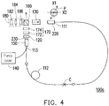
- FIG. 4 is a schematic view of a pulse laser device according to another exemplary embodiment.
- the pulse laser device 100a in this embodiment is similar to the pulse laser device 100 in FIG. 1 , and the main difference is as follows.
- the pulse laser device 100a further includes a linear section 180 disposed on the light path of the ring laser resonator, wherein the linear section 180 may include at least one of a reflecting element, a saturable absorber mirror, a Bragg grating, a dispersion compensator, and a grating pair.
- the linear section 180 includes a semiconductor saturable absorber mirror (SESAM) 182, a lens 184, and a quarter waveplate 186 sequentially arranged along a line.
- SESAM semiconductor saturable absorber mirror
- the light reflected by the output coupling device 160 passes through the quarter waveplate 186 and is focused by the lens 184 onto the SESAM 182, and the light from the SESAM passes through the lens 184, the quarter waveplate 186, the output coupling device 160, and the optical isolator 130 in sequence.
- the SESAM 182 may help to start mode-locking.
- the SESAM 182 may be replaced by graphene, carbon nanotubes, or any other type of saturable absorber.
- the pulse laser device is a mode-locked fiber ring laser with all PM fiber 110 based on nonlinear polarization rotation (NPR) mechanism.
- the laser field polarization ellipse is formed and rotates after the combination of the PM fiber and the first quarter waveplate, not along the fiber.
- the PM fiber maintains the polarizations of the two linearly polarized lights along the fast and slow axes of the PM fiber to reduce the effect of environmental variations, e.g. temperature and pressure variations.
- an environmental stable mode-locked fiber laser i.e. the pulse laser device according to the exemplary embodiments, is achieved.
Landscapes
- Physics & Mathematics (AREA)
- Electromagnetism (AREA)
- Engineering & Computer Science (AREA)
- Plasma & Fusion (AREA)
- Optics & Photonics (AREA)
- Chemical & Material Sciences (AREA)
- Materials Engineering (AREA)
- Nanotechnology (AREA)
- Lasers (AREA)
- Optical Modulation, Optical Deflection, Nonlinear Optics, Optical Demodulation, Optical Logic Elements (AREA)
Abstract
Description
- The technical field relates to a pulse laser device.
- Mode-locked ultra-short pulse fiber laser has many applications, such as micro machining, laser surgical operation, optical frequency measurement, etc. Nonlinear polarization rotation (NPR) has been used as an artificial saturable absorber in a fiber ring laser to start the mode-locking for many years. Traditionally, NPR mode-locked fiber ring laser requires the polarization of the laser to be elliptical at the input end of the fiber and nonlinear phase generated in the fiber makes the polarization ellipse rotate. To allow the polarization ellipse to rotate along the fiber, usually non-polarization-maintaining (non-PM) single mode fiber is used. The refraction index of non-PM single mode fiber can be changed by environmental temperature or pressure variation, thus, the polarization state of the laser light in the laser resonator can be changed and mode-locking may fail. Therefore, an environmental stable mode-locked fiber laser is urgent for reliably operating the ultra-short pulse fiber laser.
- A pulse laser device with a ring laser resonator is introduced herein. The laser device includes a polarization maintaining (PM) fiber, a first quarter waveplate, and an optical isolator in the ring laser resonator. The PM fiber has a light input end and a light output end and is configured to guide a first linearly polarized light with a first phase along a fast axis of the PM fiber from the light input end and a second linearly polarized light with a second phase along a slow axis of the PM fiber from the input end. The first quarter waveplate is disposed at the light output end of the PM fiber and configured to convert the first and the second linearly polarized lights into left-handed and right-handed (or right-handed and left-handed) circularly polarized lights, respectively. Mode-locking is obtained by the nonlinear polarization rotation formed through the combination of the PM fiber and the first quarter waveplate. The optical isolator is configured to unidirectionally transmit a laser pulse in the ring laser resonator. The PM fiber has at least one 90-degree-cross-splicing position to eliminate delay between the first linearly polarized light and the second linearly polarized light. The PM fiber, the first quarter waveplate, and the optical isolator are on a light path of the ring laser resonator.
- Several exemplary embodiments accompanied with figures are described in detail below to further describe the disclosure in details.
- The accompanying drawings are included to provide further understanding, and are incorporated in and constitute a part of this specification. The drawings illustrate exemplary embodiments and, together with the description, serve to explain the principles of the disclosure.
-
FIG. 1 is a schematic view of a pulse laser device according to an exemplary embodiment. -
FIG. 2A shows polarization states of the first linearly polarized light, the second linearly polarized light, and the combination thereof before and after passing through the combination of the PM fiber and the first quarter waveplate inFIG. 1 . -
FIG. 2B shows that the left-handed and right-handed circularly polarized lights after the first quarter waveplate inFIG. 1 combine into an elliptically polarized light. -
FIG. 3 shows the rotation of the principal axis L of the laser field polarization ellipse inFIGs. 2A and 2B with the change of the pump current applied to the pump laser inFIG. 1 when an external pulse is injected into the PM fiber. -
FIG. 4 is a schematic view of a pulse laser device according to another exemplary embodiment. -
FIG. 1 is a schematic view of a pulse laser device according to an exemplary embodiment. Referring toFIG. 1 , thelaser device 100 with a ring laser resonator in this embodiment includes a polarization maintaining (PM)fiber 110, afirst quarter waveplate 120, and anoptical isolator 130 in the ring laser resonator. In this embodiment, thePM fiber 110 includes a PMgain fiber section 112, which may be at least one of a section of Erbium, Ytterbium, Holmium, or Thulium-doped fiber and a Raman or Brillouin gain medium. The pulse laser device further includes apump laser 140 and a wavelength-division multiplexer (WDM) 150, and the PMgain fiber section 112 is pumped by thepump laser 140 through the wavelength-division multiplexer 150. Thepump laser 140 is, for example, a diode laser, a semiconductor laser, a solid state laser, a continuous wave fiber laser, or any other type of laser. For example, thepump laser 140 emits a light having a wavelength of 980 nm, which is transmitted to the PMgain fiber section 112 through theWDM 150. The PMgain fiber section 112 absorbs the light having the wavelength of 980 nm, and generates a light having the wavelength of 1550 nm, for example. ThePM fiber 110, thefirst quarter waveplate 120, theoptical isolator 130, and theWDM 150 are on a light path of the ring laser resonator (i.e. the ring shown inFIG. 1 ), and theoptical isolator 130 is configured to unidirectionally transmit the light having the wavelength of 1550 nm, and ensure a single direction of lasing. For example, theoptical isolator 130 makes the light having the wavelength of 1550 nm travel clockwise inFIG. 1 in the ring laser resonator. - The
PM fiber 110 has alight input end 111 and alight output end 113. Acollimator 220 and acollimator 230 are respectively disposed on thelight input end 111 and thelight output end 113. In addition, thepulse laser device 100 in this embodiment further includes anoutput coupling device 160 disposed on the light path of the ring laser resonator. Theoutput coupling device 160 includes at least one of a polarizing beam splitter (PBS) and a fiber coupler. In this embodiment, theoutput coupling device 160 is a PBS, and theoptical isolator 130 may be a polarization sensitive isolator or a polarization insensitive isolator. In other embodiments, if theoutput coupling device 160 is a fiber coupler and no PBS is used as an output coupling device, theoptical isolator 130 is a polarization sensitive isolator. - After the light having the wavelength 1550 nm passes through the
coupling device 160 and theoptical isolator 130, the light having the wavelength 1550 nm has an electric field P tilted with respect to the fast axis X1 (parallel to the y-direction inFIG. 2A ) and the slow axis X2 (parallel to the x-direction inFIG. 2A ) of thePM fiber 110. The x-direction is perpendicular to the y-direction. The light having the wavelength of 1550 nm and having the electric field P of linear polarization may be deemed a combination of a first linearly polarized light having an electric field PI parallel to the fast axis X1 and a second linearly polarized light having an electric field P2 parallel to the slow axis X2. Moreover, theoptical isolator 130 is configured to unidirectionally transmit a laser pulse in the reasonator. The light having the wavelength of 980 nm and the light having the wavelength of 1550 nm are taken as an example, but the disclosure is not limited thereto. By adopting another type ofpump laser 140, it may provide a pumping light with a wavelength other than 980 nm, and by adopting another type of gain medium, it may generate a light with a wavelength other than 1550 nm. - The
PM fiber 110 is configured to guide the first linearly polarized light with a first phase along the fast axis X1 of thePM fiber 110 from thelight input end 111 and a second linearly polarized light with a second phase along a slow axis X2 of thePM fiber 110 from theinput end 111. In this embodiment, the first phase is the same as the second phase. However, in other embodiments, the first phase is different from the second phase. - The
first quarter waveplate 120 is disposed at thelight output end 113 of thePM fiber 110 and configured to convert the first and the second linearly polarized lights into left-handed and right-handed (or right-handed and left-handed) circularly polarized lights, respectively. A linear phase difference and a nonlinear phase difference between the two pulses propagating along the fast axis X1 and the slow axis X2 become the phase difference between the two circularly polarized lights after thefirst quarter waveplate 120. In this embodiment, the amplitude of the first linearly polarized light is different from that of the second linearly polarized light, so that the amplitude of the left-handed circularly polarized light is different from that of the right-handed circularly polarized light. As a result, the left-handed circularly polarized light and the right-handed circularly polarized light combine into an elliptically polarized light with a laser field polarization ellipse having the principal axis angle dependent on the linear and nonlinear phase difference, as shown inFIGs. 2A and 2B . In this embodiment, thefirst quarter waveplate 120 has anoptical axis 122 tilted with respect to the fast axis X1 and the slow axis X2 of thePM fiber 110 by 45 degrees. - The
PM fiber 110 has at least one 90-degree-cross-splicing position C to eliminate the delay between the first linearly polarized light and the second linearly polarized light. Specifically, for example, thePM fiber 110 includes asection 114 and asection 116 spliced together at the 90-degree-cross-splicing position C, and the fast axis of thesection 114 is aligned and parallel with the slow axis of thesection 116, and the slow axis of thesection 114 is aligned and parallel with the fast axis of thesection 116. As a result, the pulse of the first linearly polarized light from thelight input end 111 and the pulse of the second linearly polarized light from thelight input end 111 may simultaneously reach thelight output end 113. Preferably, every different kind of fiber in the laser cavity has at least one 90-degree-cross-splicing to compensate the delay of the pulses propagating along the slow and fast axis in that kind of fiber. For example, assume the laser cavity has two different kinds of fibers, one is a gain fiber and the other is a passive fiber, then the gain fiber has at least one 90-degree-cross-splicing to compensate the delay caused by the gain fiber, and the other passive fiber has at least one 90-degree-cross-splicing to compensate the delay caused by the passive fiber. Where at least one 90-degree-cross-splicing can be applied to the middle or to the positions of length ratio of 1:2:1 of that kind of fiber. - In this embodiment, the
pulse laser device 100 is a mode-locked fiber ring laser with allPM fiber 110 based on nonlinear polarization rotation (NPR) mechanism. The NPR mechanism happens from the combination of inputting linearly polarized light into thePM fiber 110 with the electric field P tilted with respect to the slow axis X2 and the fast axis X1 of thePM fiber 110 and afirst quarter waveplate 120 mounted after thePM fiber 110 with theoptical axis 122 tilted 45° from the fast axis X1 and the slow axis X2 of thePM fiber 110. Thefirst quarter waveplate 120 transforms the two linearly polarized lights from the fast and the slow axes X1 and X2 into left- and right-handed circularly polarized lights respectively. The superposition of the two circularly polarized is elliptically polarized light with the angle of the principal axis depending on the nonlinear phase difference of the two light fields obtained in the fast and slow axes X1 and X2 of the PM fiber. This mimics the NPR effect in a conventional NPR mode-locked fiber laser constructed with non-PM fiber. Different from a conventional NPR mode-locked fiber laser, in this embodiment, the laser field polarization ellipse is formed and rotates after the combination of thePM fiber 110 and thefirst quarter waveplate 120, not along the fiber. ThePM fiber 110 maintains the polarizations of the two linearly polarized lights along the fast and slow axes X1 and X2 to reduce the effect of environmental variations, e.g. temperature and pressure variations. As a result, an environmental stable mode-locked fiber laser, i.e. thepulse laser device 100, is achieved. - In addition, due to Kerr effect, when the pump current of the
pump laser 140 is changed (e.g. changed to 100 mA, 200 mA, 300 mA, 400 mA, 500 mA, 600 mA, 700 mA, 800 mA, 900 mA, and 1000 mA), the principal axis L of the laser field polarization ellipse after thefirst quarter waveplate 120 rotates as shown inFIG. 3 , but the shape of the ellipse is not changed. The output coupling device 160 (i.e. a PBS) allows light with high intensity to pass through and reflects light with lower intensity, which facilitates the generation of mode-locking. After the mode-locking is started, the reflected light with lower intensity forms an output pulse laser beam. In other embodiments, an additional fiber coupler may also be spliced in the ring laser resonator to output another pulse laser beam. - In this embodiment, the
pulse laser device 100 further includes apolarization controlling device 170 disposed on the light path of the ring laser resonator between thefirst quarter waveplate 120 and theoptical isolator 130. Thepolarization controlling device 170 may include ahalf waveplate 172, asecond quarter waveplate 174, or a combination thereof. In this embodiment, thepolarization controlling device 170 includes the half waveplate 172 and thesecond quarter waveplate 174. The optical axes of the half waveplate 172 and thesecond quarter waveplate 174 may be rotated to appropriate directions to allow high intensity light to pass through the output coupling device 160 (i.e. the PBS), compensate a residual linear phase difference, and facilitate the generation of mode-locking. In this embodiment, thehalf waveplate 172 is disposed between thefirst quarter waveplate 120 and thesecond quarter waveplate 174. However, in other embodiments, the position of the half waveplate 172 and the position of thesecond quarter waveplate 174 may be interchanged; that is, thesecond quarter waveplate 174 may be disposed between thefirst quarter waveplate 120 and thehalf waveplate 172. Furthermore, in another embodiment, thepolarization controlling device 170 can be installed before thefirst quarter waveplate 120, while both of them are rotatable to realize the transformation of the two linearly polarized lights into circularly polarized lights and also functioning the rotation of the principal axis of the superposed polarization ellipse. - Moreover, in another embodiment, at least one of a half waveplate and an other retardation waveplate (i.e. a waveplate having retardation different from half a wavelength, i.e., different from the retardation of a half waveplate), e.g. a quarter waveplate, may be disposed on the light path of the ring laser resonator and at the
light input end 111 of thePM fiber 110 to adjust the light field amplitude inputted to the fast and slow axes X1 and X2 of thePM fiber 110. If the other retardation waveplate is disposed, the first phase of the first linearly polarized light at thelight input end 111 is different from the second phase of the second linearly polarized light at thelight input end 111. -
FIG. 4 is a schematic view of a pulse laser device according to another exemplary embodiment. Referring toFIG. 4 the pulse laser device 100a in this embodiment is similar to thepulse laser device 100 inFIG. 1 , and the main difference is as follows. In this embodiment, the pulse laser device 100a further includes alinear section 180 disposed on the light path of the ring laser resonator, wherein thelinear section 180 may include at least one of a reflecting element, a saturable absorber mirror, a Bragg grating, a dispersion compensator, and a grating pair. In this embodiment, thelinear section 180 includes a semiconductor saturable absorber mirror (SESAM) 182, alens 184, and aquarter waveplate 186 sequentially arranged along a line. The light reflected by the output coupling device 160 (i.e. the PBS) passes through the quarter waveplate 186 and is focused by thelens 184 onto theSESAM 182, and the light from the SESAM passes through thelens 184, thequarter waveplate 186, theoutput coupling device 160, and theoptical isolator 130 in sequence. TheSESAM 182 may help to start mode-locking. In other embodiments, theSESAM 182 may be replaced by graphene, carbon nanotubes, or any other type of saturable absorber. - In conclusion, the pulse laser device according to the exemplary embodiments is a mode-locked fiber ring laser with all
PM fiber 110 based on nonlinear polarization rotation (NPR) mechanism. The laser field polarization ellipse is formed and rotates after the combination of the PM fiber and the first quarter waveplate, not along the fiber. The PM fiber maintains the polarizations of the two linearly polarized lights along the fast and slow axes of the PM fiber to reduce the effect of environmental variations, e.g. temperature and pressure variations. As a result, an environmental stable mode-locked fiber laser, i.e. the pulse laser device according to the exemplary embodiments, is achieved.
Claims (15)
- A pulse laser device (100, 100a) with a ring laser resonator, the pulse laser device (100, 100a) comprising:a polarization maintaining (PM) fiber (110) having a light input end (111) and a light output end (113) and configured to guide a first linearly polarized light with a first phase along a fast axis (X1) of the PM fiber (110) from the light input end (111) and a second linearly polarized light with a second phase along a slow axis (X2) of the PM fiber (110) from the input end;a first quarter waveplate (120) disposed at the light output end (113) of the PM fiber (110) and configured to convert the first and the second linearly polarized lights into left-handed and right-handed (or right-handed and left-handed) circularly polarized lights, respectively; andan optical isolator (130) configured to unidirectionally transmit a laser pulse in the ring laser resonator,wherein the PM fiber (110) has at least one 90-degree-cross-splicing position (C) to eliminate delay between the first linearly polarized light and the second linearly polarized light, and wherein the PM fiber (110), the first quarter waveplate (120), and the optical isolator (130) are on a light path of the ring laser resonator.
- The pulse laser device (100, 100a) according to claim 1, wherein the first phase is the same as the second phase.
- The pulse laser device (100, 100a) according to claim 1, wherein the first phase is different from the second phase.
- The pulse laser device (100, 100a) according to claim 1, wherein an amplitude of the first linearly polarized light is different from an amplitude of the second linearly polarized light.
- The pulse laser device (100, 100a) according to claim 1, wherein the first quarter waveplate (120) has an optical axis (122) tilted with respect to the fast axis (X1) and the slow axis (X2) of the PM fiber (110) by 45 degrees.
- The pulse laser device (100, 100a) according to claim 1 further comprising a half waveplate disposed on the light path of the ring laser resonator between the first quarter waveplate (120) and the collimator (230) disposed on the light output end (113).
- The pulse laser device (100, 100a) according to claim 1, wherein the PM fiber (110) includes at least one of a section of Erbium, Ytterbium, Holmium or Thulium-doped fiber and a Raman or Brillouin gain medium.
- The pulse laser device (100, 100a) according to claim 7 further comprising a pump laser (140) and a wavelength-division multiplexer (150), wherein the at least one of a section of Erbium, Ytterbium, Holmium, or Thulium-doped fiber and a Raman or Brillouin gain medium is pumped by the pump laser (140) through the wavelength-division multiplexer (150).
- The pulse laser device (100, 100a) according to claim 1 further comprising a polarization controlling device (170) disposed on the light path of the ring laser resonator between the first quarter waveplate (120) and the optical isolator (130).
- The pulse laser device (100, 100a) according to claim 9, wherein the polarization controlling device (170) comprises a half waveplate (172), a second quarter waveplate (174), or a combination thereof.
- The pulse laser device (100, 100a) according to claim 1 further comprising an output coupling device (160) disposed on the light path of the ring laser resonator.
- The pulse laser device (100, 100a) according to claim 11, wherein the output coupling device (160) comprises at least one of a polarizing beam splitter and a fiber coupler.
- The pulse laser device (100a) according to claim 1 further comprising a linear section (180) disposed on the light path of the ring laser resonator, wherein the linear section (180) comprises at least one of a reflecting element, a saturable absorber mirror, a Bragg grating, a dispersion compensator, and a grating pair.
- The pulse laser device (100, 100a) according to claim 1 further comprising at least one of a half waveplate (172) and a waveplate having retardation different from half a wavelength, disposed on the light path of the ring laser resonator and at the light input end (111) of the PM fiber (110).
- The pulse laser device (100, 100a) according to claim 1 wherein at least one 90-degree-cross-splicing is applied to the middle or to the positions of a length-ratio of 1:2:1 of each different kind of fiber in the laser cavity.
Applications Claiming Priority (1)
| Application Number | Priority Date | Filing Date | Title |
|---|---|---|---|
| US15/643,456 US10367328B2 (en) | 2017-07-06 | 2017-07-06 | Pulse laser device |
Publications (2)
| Publication Number | Publication Date |
|---|---|
| EP3429038A1 true EP3429038A1 (en) | 2019-01-16 |
| EP3429038B1 EP3429038B1 (en) | 2020-04-29 |
Family
ID=62846057
Family Applications (1)
| Application Number | Title | Priority Date | Filing Date |
|---|---|---|---|
| EP18181443.5A Active EP3429038B1 (en) | 2017-07-06 | 2018-07-03 | Mode-locked laser device |
Country Status (2)
| Country | Link |
|---|---|
| US (1) | US10367328B2 (en) |
| EP (1) | EP3429038B1 (en) |
Families Citing this family (9)
| Publication number | Priority date | Publication date | Assignee | Title |
|---|---|---|---|---|
| DE102016118391B4 (en) * | 2016-09-28 | 2019-03-14 | Fraunhofer-Gesellschaft zur Förderung der angewandten Forschung e.V. | Short-pulse laser system |
| ES2777650T3 (en) * | 2017-02-13 | 2020-08-05 | Max-Planck-Gesellschaft Zur Förderung Der Wss Ev | Laser pulse generation and spectroscopy using the temporal Talbot effect and corresponding devices |
| RU2747724C1 (en) * | 2020-07-23 | 2021-05-13 | Общество С Ограниченной Ответственностью "Научно-Техническое Объединение "Ирэ-Полюс" | Method of stable autogeneration of ultrashort laser pulses in a polarizing fiber ring resonator and a laser based on it |
| JP7534890B2 (en) * | 2020-08-21 | 2024-08-15 | 浜松ホトニクス株式会社 | Fiber Laser Device |
| US11387912B2 (en) * | 2020-11-19 | 2022-07-12 | Fujitsu Limited | Wavelength converter and fiber optic transmission system |
| CN113206443B (en) * | 2021-04-26 | 2022-06-03 | 武汉大学 | Terahertz gas laser |
| CN113594839B (en) * | 2021-08-06 | 2022-12-09 | 深圳市杰普特光电股份有限公司 | Optical fiber oscillator |
| CN113725711B (en) * | 2021-08-25 | 2022-11-08 | 江苏科技大学 | Optical vortex optical fiber laser based on double vortex wave plates |
| CN120933756B (en) * | 2025-08-04 | 2026-03-06 | 铜仁学院 | A system and method for controlling the polarization state of a high-power laser pulse |
Citations (2)
| Publication number | Priority date | Publication date | Assignee | Title |
|---|---|---|---|---|
| KR20120058275A (en) * | 2010-11-29 | 2012-06-07 | 한국과학기술원 | Automation of Passive Mode-locking Process of Fiber Femtosecond Pulse Lasers |
| WO2015064957A1 (en) * | 2013-10-28 | 2015-05-07 | Korea Research Institute Of Standards And Science | Dual optical-comb femtosecond optical fiber laser |
Family Cites Families (17)
| Publication number | Priority date | Publication date | Assignee | Title |
|---|---|---|---|---|
| US5050183A (en) | 1990-11-05 | 1991-09-17 | The United States Of America As Represented By The Secretary Of The Navy | Figure eight shaped coherent optical pulse source |
| KR960015900B1 (en) * | 1993-04-22 | 1996-11-23 | 국방과학연구소 | Polarimetric fiber laser sensor |
| US5689519A (en) | 1993-12-20 | 1997-11-18 | Imra America, Inc. | Environmentally stable passively modelocked fiber laser pulse source |
| US5513194A (en) | 1994-06-30 | 1996-04-30 | Massachusetts Institute Of Technology | Stretched-pulse fiber laser |
| KR100350232B1 (en) | 2000-09-21 | 2002-08-27 | 광주과학기술원 | Pulsed figure-eight optical fiber laser using unbalanced nonlinear optical loop mirror |
| US7251258B2 (en) * | 2002-12-12 | 2007-07-31 | Cornell Research Foundation, Inc. | Femtosecond ytterbium fiber laser with photonic crystal fiber for dispersion control |
| US8416817B2 (en) | 2006-09-18 | 2013-04-09 | Cornell University | All-normal-dispersion femtosecond fiber laser |
| US7817684B2 (en) | 2006-11-16 | 2010-10-19 | Ofs Fitel Llc | Passively modelocked figure eight fiber laser |
| US7817681B2 (en) * | 2008-06-26 | 2010-10-19 | Corning Incorporated | Pulse stretching optical fiber and related systems and methods |
| US7940816B2 (en) | 2008-09-05 | 2011-05-10 | Ofs Fitel Llc | Figure eight fiber laser for ultrashort pulse generation |
| JP4683099B2 (en) * | 2008-09-16 | 2011-05-11 | 沖電気工業株式会社 | Optical multilevel modulation signal generator |
| EP2515393A2 (en) | 2009-12-18 | 2012-10-24 | Femtolight Co., Ltd | Environmentally stabilised optical-fibre mode-locked laser generating device having an achromatic quarter wave plate |
| US8494014B2 (en) | 2011-04-08 | 2013-07-23 | Auckland Uniservices Limited | Laser device |
| FR2977988B1 (en) * | 2011-07-11 | 2014-03-07 | Ecole Polytech | PASSIVE DEVICE AND METHOD FOR COHERENT COMBINATION OF TWO OPTICALLY AMPLIFIED AND / OR SPECIFALLY EXTENDED OPTICAL BEAMS. |
| EP2637265B1 (en) | 2012-03-05 | 2018-08-29 | Menlo Systems GmbH | Laser with non-linear optical loop mirror |
| TWI509923B (en) | 2013-05-20 | 2015-11-21 | Nat Univ Tsing Hua | Fiber laser |
| EP2846421A1 (en) | 2013-09-06 | 2015-03-11 | Menlo Systems GmbH | Laser with non-linear optical loop mirror |
-
2017
- 2017-07-06 US US15/643,456 patent/US10367328B2/en active Active
-
2018
- 2018-07-03 EP EP18181443.5A patent/EP3429038B1/en active Active
Patent Citations (2)
| Publication number | Priority date | Publication date | Assignee | Title |
|---|---|---|---|---|
| KR20120058275A (en) * | 2010-11-29 | 2012-06-07 | 한국과학기술원 | Automation of Passive Mode-locking Process of Fiber Femtosecond Pulse Lasers |
| WO2015064957A1 (en) * | 2013-10-28 | 2015-05-07 | Korea Research Institute Of Standards And Science | Dual optical-comb femtosecond optical fiber laser |
Also Published As
| Publication number | Publication date |
|---|---|
| US10367328B2 (en) | 2019-07-30 |
| EP3429038B1 (en) | 2020-04-29 |
| US20190013639A1 (en) | 2019-01-10 |
Similar Documents
| Publication | Publication Date | Title |
|---|---|---|
| EP3429038B1 (en) | Mode-locked laser device | |
| US9819141B2 (en) | Compact fiber short pulse laser sources | |
| US9059564B2 (en) | Short-pulse fiber-laser | |
| Li et al. | High-power ultrafast Yb: fiber laser frequency combs using commercially available components and basic fiber tools | |
| US8873601B2 (en) | Laser with non-linear optical loop mirror | |
| CN101854022B (en) | Passive mode-locking fiber laser with double-wavelength short pulse output | |
| JP3803979B2 (en) | Passive mode-locked laser that is stable against environmental changes | |
| US9276372B2 (en) | Laser with non-linear optical loop mirror | |
| CN112542761B (en) | Linear cavity mode-locked fiber laser based on phase bias and control method | |
| CN113206426B (en) | A compact high repetition rate fully polarization-maintaining fiber mode-locked laser | |
| CN110364923A (en) | A fully polarization-maintaining fiber mode-locked laser based on phase bias | |
| EP2515393A2 (en) | Environmentally stabilised optical-fibre mode-locked laser generating device having an achromatic quarter wave plate | |
| CN101588013A (en) | Polarization-maintaining photonic crystal fiber beam laser | |
| CN114628980B (en) | A nonlinear polarization filtering method, device and application equipment | |
| US7551652B1 (en) | Simultaneously Q-switched fiber lasers using a shared modulator | |
| CN107895881A (en) | The fine nonlinear polarization rotation mode-locked laser of full polarization | |
| CN213602177U (en) | Linear Cavity Mode-locked Fiber Laser Based on Phase Bias | |
| US7317740B2 (en) | Mode locker for fiber laser | |
| Rumpel et al. | Resonant Waveguide Gratings–Versatile Devices for Laser Engineering: Accurate tailoring of the spectral, temporal and spatial parameters of your laser systems | |
| CN102570275B (en) | Laser capable of tuning wavelengths | |
| CN121416965B (en) | Linear cavity nonlinear amplification ring mirror mode-locked fiber laser | |
| CN119834038B (en) | A method to eliminate the birefringence filtering effect of fully polarization-maintaining mode-locked fiber laser | |
| EP3652821B1 (en) | Polarized fiber-laser | |
| CN119362126A (en) | Highly stable self-mode-locked fiber laser based on phase modulation | |
| CN105659926B (en) | 1083nm wave band narrow line width regulatable polarization-maintaining fiber laser |
Legal Events
| Date | Code | Title | Description |
|---|---|---|---|
| PUAI | Public reference made under article 153(3) epc to a published international application that has entered the european phase |
Free format text: ORIGINAL CODE: 0009012 |
|
| STAA | Information on the status of an ep patent application or granted ep patent |
Free format text: STATUS: REQUEST FOR EXAMINATION WAS MADE |
|
| 17P | Request for examination filed |
Effective date: 20180703 |
|
| AK | Designated contracting states |
Kind code of ref document: A1 Designated state(s): AL AT BE BG CH CY CZ DE DK EE ES FI FR GB GR HR HU IE IS IT LI LT LU LV MC MK MT NL NO PL PT RO RS SE SI SK SM TR |
|
| AX | Request for extension of the european patent |
Extension state: BA ME |
|
| RBV | Designated contracting states (corrected) |
Designated state(s): AL AT BE BG CH CY CZ DE DK EE ES FI FR GB GR HR HU IE IS IT LI LT LU LV MC MK MT NL NO PL PT RO RS SE SI SK SM TR |
|
| RIC1 | Information provided on ipc code assigned before grant |
Ipc: H01S 3/11 20060101ALI20191017BHEP Ipc: H01S 3/067 20060101AFI20191017BHEP Ipc: H01S 5/50 20060101ALN20191017BHEP |
|
| GRAP | Despatch of communication of intention to grant a patent |
Free format text: ORIGINAL CODE: EPIDOSNIGR1 |
|
| RIC1 | Information provided on ipc code assigned before grant |
Ipc: H01S 3/11 20060101ALI20191108BHEP Ipc: H01S 3/067 20060101AFI20191108BHEP Ipc: H01S 5/50 20060101ALN20191108BHEP |
|
| STAA | Information on the status of an ep patent application or granted ep patent |
Free format text: STATUS: GRANT OF PATENT IS INTENDED |
|
| INTG | Intention to grant announced |
Effective date: 20191219 |
|
| GRAS | Grant fee paid |
Free format text: ORIGINAL CODE: EPIDOSNIGR3 |
|
| GRAA | (expected) grant |
Free format text: ORIGINAL CODE: 0009210 |
|
| STAA | Information on the status of an ep patent application or granted ep patent |
Free format text: STATUS: THE PATENT HAS BEEN GRANTED |
|
| AK | Designated contracting states |
Kind code of ref document: B1 Designated state(s): AL AT BE BG CH CY CZ DE DK EE ES FI FR GB GR HR HU IE IS IT LI LT LU LV MC MK MT NL NO PL PT RO RS SE SI SK SM TR |
|
| REG | Reference to a national code |
Ref country code: GB Ref legal event code: FG4D |
|
| REG | Reference to a national code |
Ref country code: CH Ref legal event code: EP |
|
| REG | Reference to a national code |
Ref country code: DE Ref legal event code: R096 Ref document number: 602018004126 Country of ref document: DE |
|
| REG | Reference to a national code |
Ref country code: AT Ref legal event code: REF Ref document number: 1264713 Country of ref document: AT Kind code of ref document: T Effective date: 20200515 |
|
| REG | Reference to a national code |
Ref country code: IE Ref legal event code: FG4D |
|
| REG | Reference to a national code |
Ref country code: NL Ref legal event code: MP Effective date: 20200429 |
|
| REG | Reference to a national code |
Ref country code: LT Ref legal event code: MG4D |
|
| PG25 | Lapsed in a contracting state [announced via postgrant information from national office to epo] |
Ref country code: IS Free format text: LAPSE BECAUSE OF FAILURE TO SUBMIT A TRANSLATION OF THE DESCRIPTION OR TO PAY THE FEE WITHIN THE PRESCRIBED TIME-LIMIT Effective date: 20200829 Ref country code: FI Free format text: LAPSE BECAUSE OF FAILURE TO SUBMIT A TRANSLATION OF THE DESCRIPTION OR TO PAY THE FEE WITHIN THE PRESCRIBED TIME-LIMIT Effective date: 20200429 Ref country code: NO Free format text: LAPSE BECAUSE OF FAILURE TO SUBMIT A TRANSLATION OF THE DESCRIPTION OR TO PAY THE FEE WITHIN THE PRESCRIBED TIME-LIMIT Effective date: 20200729 Ref country code: PT Free format text: LAPSE BECAUSE OF FAILURE TO SUBMIT A TRANSLATION OF THE DESCRIPTION OR TO PAY THE FEE WITHIN THE PRESCRIBED TIME-LIMIT Effective date: 20200831 Ref country code: SE Free format text: LAPSE BECAUSE OF FAILURE TO SUBMIT A TRANSLATION OF THE DESCRIPTION OR TO PAY THE FEE WITHIN THE PRESCRIBED TIME-LIMIT Effective date: 20200429 Ref country code: LT Free format text: LAPSE BECAUSE OF FAILURE TO SUBMIT A TRANSLATION OF THE DESCRIPTION OR TO PAY THE FEE WITHIN THE PRESCRIBED TIME-LIMIT Effective date: 20200429 Ref country code: GR Free format text: LAPSE BECAUSE OF FAILURE TO SUBMIT A TRANSLATION OF THE DESCRIPTION OR TO PAY THE FEE WITHIN THE PRESCRIBED TIME-LIMIT Effective date: 20200730 |
|
| REG | Reference to a national code |
Ref country code: AT Ref legal event code: MK05 Ref document number: 1264713 Country of ref document: AT Kind code of ref document: T Effective date: 20200429 |
|
| PG25 | Lapsed in a contracting state [announced via postgrant information from national office to epo] |
Ref country code: BG Free format text: LAPSE BECAUSE OF FAILURE TO SUBMIT A TRANSLATION OF THE DESCRIPTION OR TO PAY THE FEE WITHIN THE PRESCRIBED TIME-LIMIT Effective date: 20200729 Ref country code: HR Free format text: LAPSE BECAUSE OF FAILURE TO SUBMIT A TRANSLATION OF THE DESCRIPTION OR TO PAY THE FEE WITHIN THE PRESCRIBED TIME-LIMIT Effective date: 20200429 Ref country code: LV Free format text: LAPSE BECAUSE OF FAILURE TO SUBMIT A TRANSLATION OF THE DESCRIPTION OR TO PAY THE FEE WITHIN THE PRESCRIBED TIME-LIMIT Effective date: 20200429 Ref country code: RS Free format text: LAPSE BECAUSE OF FAILURE TO SUBMIT A TRANSLATION OF THE DESCRIPTION OR TO PAY THE FEE WITHIN THE PRESCRIBED TIME-LIMIT Effective date: 20200429 |
|
| PG25 | Lapsed in a contracting state [announced via postgrant information from national office to epo] |
Ref country code: NL Free format text: LAPSE BECAUSE OF FAILURE TO SUBMIT A TRANSLATION OF THE DESCRIPTION OR TO PAY THE FEE WITHIN THE PRESCRIBED TIME-LIMIT Effective date: 20200429 Ref country code: AL Free format text: LAPSE BECAUSE OF FAILURE TO SUBMIT A TRANSLATION OF THE DESCRIPTION OR TO PAY THE FEE WITHIN THE PRESCRIBED TIME-LIMIT Effective date: 20200429 |
|
| PG25 | Lapsed in a contracting state [announced via postgrant information from national office to epo] |
Ref country code: AT Free format text: LAPSE BECAUSE OF FAILURE TO SUBMIT A TRANSLATION OF THE DESCRIPTION OR TO PAY THE FEE WITHIN THE PRESCRIBED TIME-LIMIT Effective date: 20200429 Ref country code: ES Free format text: LAPSE BECAUSE OF FAILURE TO SUBMIT A TRANSLATION OF THE DESCRIPTION OR TO PAY THE FEE WITHIN THE PRESCRIBED TIME-LIMIT Effective date: 20200429 Ref country code: DK Free format text: LAPSE BECAUSE OF FAILURE TO SUBMIT A TRANSLATION OF THE DESCRIPTION OR TO PAY THE FEE WITHIN THE PRESCRIBED TIME-LIMIT Effective date: 20200429 Ref country code: RO Free format text: LAPSE BECAUSE OF FAILURE TO SUBMIT A TRANSLATION OF THE DESCRIPTION OR TO PAY THE FEE WITHIN THE PRESCRIBED TIME-LIMIT Effective date: 20200429 Ref country code: CZ Free format text: LAPSE BECAUSE OF FAILURE TO SUBMIT A TRANSLATION OF THE DESCRIPTION OR TO PAY THE FEE WITHIN THE PRESCRIBED TIME-LIMIT Effective date: 20200429 Ref country code: IT Free format text: LAPSE BECAUSE OF FAILURE TO SUBMIT A TRANSLATION OF THE DESCRIPTION OR TO PAY THE FEE WITHIN THE PRESCRIBED TIME-LIMIT Effective date: 20200429 Ref country code: EE Free format text: LAPSE BECAUSE OF FAILURE TO SUBMIT A TRANSLATION OF THE DESCRIPTION OR TO PAY THE FEE WITHIN THE PRESCRIBED TIME-LIMIT Effective date: 20200429 Ref country code: SM Free format text: LAPSE BECAUSE OF FAILURE TO SUBMIT A TRANSLATION OF THE DESCRIPTION OR TO PAY THE FEE WITHIN THE PRESCRIBED TIME-LIMIT Effective date: 20200429 |
|
| REG | Reference to a national code |
Ref country code: DE Ref legal event code: R097 Ref document number: 602018004126 Country of ref document: DE |
|
| PG25 | Lapsed in a contracting state [announced via postgrant information from national office to epo] |
Ref country code: MC Free format text: LAPSE BECAUSE OF FAILURE TO SUBMIT A TRANSLATION OF THE DESCRIPTION OR TO PAY THE FEE WITHIN THE PRESCRIBED TIME-LIMIT Effective date: 20200429 Ref country code: PL Free format text: LAPSE BECAUSE OF FAILURE TO SUBMIT A TRANSLATION OF THE DESCRIPTION OR TO PAY THE FEE WITHIN THE PRESCRIBED TIME-LIMIT Effective date: 20200429 Ref country code: SK Free format text: LAPSE BECAUSE OF FAILURE TO SUBMIT A TRANSLATION OF THE DESCRIPTION OR TO PAY THE FEE WITHIN THE PRESCRIBED TIME-LIMIT Effective date: 20200429 |
|
| PLBE | No opposition filed within time limit |
Free format text: ORIGINAL CODE: 0009261 |
|
| STAA | Information on the status of an ep patent application or granted ep patent |
Free format text: STATUS: NO OPPOSITION FILED WITHIN TIME LIMIT |
|
| 26N | No opposition filed |
Effective date: 20210201 |
|
| REG | Reference to a national code |
Ref country code: BE Ref legal event code: MM Effective date: 20200731 |
|
| PG25 | Lapsed in a contracting state [announced via postgrant information from national office to epo] |
Ref country code: FR Free format text: LAPSE BECAUSE OF NON-PAYMENT OF DUE FEES Effective date: 20200731 Ref country code: LU Free format text: LAPSE BECAUSE OF NON-PAYMENT OF DUE FEES Effective date: 20200703 Ref country code: IE Free format text: LAPSE BECAUSE OF NON-PAYMENT OF DUE FEES Effective date: 20200703 |
|
| PG25 | Lapsed in a contracting state [announced via postgrant information from national office to epo] |
Ref country code: SI Free format text: LAPSE BECAUSE OF FAILURE TO SUBMIT A TRANSLATION OF THE DESCRIPTION OR TO PAY THE FEE WITHIN THE PRESCRIBED TIME-LIMIT Effective date: 20200429 Ref country code: BE Free format text: LAPSE BECAUSE OF NON-PAYMENT OF DUE FEES Effective date: 20200731 |
|
| REG | Reference to a national code |
Ref country code: CH Ref legal event code: PL |
|
| PG25 | Lapsed in a contracting state [announced via postgrant information from national office to epo] |
Ref country code: LI Free format text: LAPSE BECAUSE OF NON-PAYMENT OF DUE FEES Effective date: 20210731 Ref country code: CH Free format text: LAPSE BECAUSE OF NON-PAYMENT OF DUE FEES Effective date: 20210731 |
|
| PG25 | Lapsed in a contracting state [announced via postgrant information from national office to epo] |
Ref country code: TR Free format text: LAPSE BECAUSE OF FAILURE TO SUBMIT A TRANSLATION OF THE DESCRIPTION OR TO PAY THE FEE WITHIN THE PRESCRIBED TIME-LIMIT Effective date: 20200429 Ref country code: MT Free format text: LAPSE BECAUSE OF FAILURE TO SUBMIT A TRANSLATION OF THE DESCRIPTION OR TO PAY THE FEE WITHIN THE PRESCRIBED TIME-LIMIT Effective date: 20200429 Ref country code: CY Free format text: LAPSE BECAUSE OF FAILURE TO SUBMIT A TRANSLATION OF THE DESCRIPTION OR TO PAY THE FEE WITHIN THE PRESCRIBED TIME-LIMIT Effective date: 20200429 |
|
| PG25 | Lapsed in a contracting state [announced via postgrant information from national office to epo] |
Ref country code: MK Free format text: LAPSE BECAUSE OF FAILURE TO SUBMIT A TRANSLATION OF THE DESCRIPTION OR TO PAY THE FEE WITHIN THE PRESCRIBED TIME-LIMIT Effective date: 20200429 |
|
| GBPC | Gb: european patent ceased through non-payment of renewal fee |
Effective date: 20220703 |
|
| PG25 | Lapsed in a contracting state [announced via postgrant information from national office to epo] |
Ref country code: GB Free format text: LAPSE BECAUSE OF NON-PAYMENT OF DUE FEES Effective date: 20220703 |
|
| PGFP | Annual fee paid to national office [announced via postgrant information from national office to epo] |
Ref country code: DE Payment date: 20250729 Year of fee payment: 8 |