EP3428914A1 - Ultra-thin schroeder diffuser - Google Patents
Ultra-thin schroeder diffuser Download PDFInfo
- Publication number
- EP3428914A1 EP3428914A1 EP17781961.2A EP17781961A EP3428914A1 EP 3428914 A1 EP3428914 A1 EP 3428914A1 EP 17781961 A EP17781961 A EP 17781961A EP 3428914 A1 EP3428914 A1 EP 3428914A1
- Authority
- EP
- European Patent Office
- Prior art keywords
- schroeder
- ultra
- thin
- unit cell
- diffuser
- Prior art date
- Legal status (The legal status is an assumption and is not a legal conclusion. Google has not performed a legal analysis and makes no representation as to the accuracy of the status listed.)
- Withdrawn
Links
Images

Classifications
-
- G—PHYSICS
- G10—MUSICAL INSTRUMENTS; ACOUSTICS
- G10K—SOUND-PRODUCING DEVICES; METHODS OR DEVICES FOR PROTECTING AGAINST, OR FOR DAMPING, NOISE OR OTHER ACOUSTIC WAVES IN GENERAL; ACOUSTICS NOT OTHERWISE PROVIDED FOR
- G10K11/00—Methods or devices for transmitting, conducting or directing sound in general; Methods or devices for protecting against, or for damping, noise or other acoustic waves in general
- G10K11/18—Methods or devices for transmitting, conducting or directing sound
- G10K11/20—Reflecting arrangements
-
- G—PHYSICS
- G10—MUSICAL INSTRUMENTS; ACOUSTICS
- G10K—SOUND-PRODUCING DEVICES; METHODS OR DEVICES FOR PROTECTING AGAINST, OR FOR DAMPING, NOISE OR OTHER ACOUSTIC WAVES IN GENERAL; ACOUSTICS NOT OTHERWISE PROVIDED FOR
- G10K11/00—Methods or devices for transmitting, conducting or directing sound in general; Methods or devices for protecting against, or for damping, noise or other acoustic waves in general
- G10K11/18—Methods or devices for transmitting, conducting or directing sound
- G10K11/26—Sound-focusing or directing, e.g. scanning
- G10K11/28—Sound-focusing or directing, e.g. scanning using reflection, e.g. parabolic reflectors
Definitions
- the invention relates to an ultra-thin Schroeder diffuser, and belongs to the field of acoustics.
- a conventional Schroeder acoustic structure is provided with multiple unit cells, and an opening width and a bottom width of the unit cell are uniform, resulting in a thicker thickness of the Schroeder acoustic structure, generally ⁇ /2 , as shown in Figs. 1 and 2 , which is not conducive to the integration of acoustic devices.
- the present invention in order to overcome the deficiencies in the prior art, provides an ultra-thin Schroeder diffuser having a thickness of 1/10 of a conventional Schroeder diffuser and a smaller volume.
- an ultra-thin Schroeder diffuser which comprises a backing-plate, wherein the backing-plate is provided with 7 ⁇ p rows and 7 ⁇ q columns of unit cells, p and q are integers greater than or equal to 1, a side length of the square unit cell is 0.48 ⁇ , a depth of the square unit cell is 0.04 ⁇ , the unit cell is provided with a square neck, a side length of the square neck is less than the side length of the unit cell, a depth of the neck is 0.01 ⁇ , ⁇ is a wavelength of the diffuser corresponding to the design at a center frequency f 0 , the neck widths w of different unit cells are different, and a distribution of the widths satisfies a certain sequence, so that expected phase distribution is achieved in the center frequency or multiple frequencies around the center frequency.
- a final diffuse reflection effect can be achieved within a certain bandwidth around the center frequency f 0 .
- the p is 2, and the q is 2.
- the backing-plate has an acoustic impedance of at least 100 times an acoustic impedance of air.
- a certain center frequency f 0 needs to be selected when setting the diffuser. Center positions of two adjacent unit cells are spaced by ⁇ /2.
- the diffuser can be designed as single frequency and multi-frequency Schroder diffusers. A unit phase response of the single frequency diffuser is designed for the center frequency f 0 .
- the multi-frequency Schroeder diffuser is designed with mixedly arranged unit cells for multiple frequencies around the center frequency f 0 to achieve more broadband diffuse reflection.
- a target frequency of four is selected for the multi-frequency Schroeder diffuser.
- the invention can implement broadband sound wave diffuse reflection, has a comparable performance of diffuse reflection to the conventional Schroeder diffusers, and can reduce a material thickness in the meanwhile; the thickness of the invention is ⁇ /20 only in comparison to a conventional Schroeder thickness ⁇ /2, which is convenient to use in practice.
- an ultra-thin Schroeder unit is an ultra-thin acoustic unit cell, a thinness of which is ⁇ /20 only, and a width thereof is the same as that of a conventional Schroeder unit cell.
- the unit cell structure is as shown in Fig. 4 .
- a neck and a bottom of the unit cell have different widths, the neck width is w, and the bottom width of the unit cell is 0.48 ⁇ , and a resonance effect of the acoustic unit cell produces the same acoustic attributes as that of the conventional unit cell structure, thus achieving the effects similar to the conventional Schroeder diffuser.
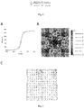
- Fig. 5 shows a design of an ultra-thin Schroeder diffuser.
- Fig. 5A shows an analytical and simulated relationship between the phase shift and the geometrical parameter w. We control the phase shift of the unit cell by changing w.
- Triangles in Fig. 5A show phases 2 ⁇ ⁇ (0-6/7). These seven discrete phases provide seven values needed in a Schroeder sequence.
- Fig. 5B shows]7 ⁇ 7 unit cells, numbers 0 to 6 represent the phase response of seven cells corresponding to 2 ⁇ ⁇ (0-6/7), which are corresponding to seven points in Fig. 5A , and a final ultra-thin Schroeder diffuser sample can be designed through the sequence.
- a value range of w is as shown in Fig. 5A .
- the sample size can be proportionally adjusted according to a working wavelength.
- L i are a set of sound pressure levels (SPLs) in the polar response
- n is the number of receivers in the experiment
- subscript ⁇ is the angle of incidence.
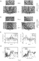
- Fig. 6 shows numerical simulation and experimental results of an ultra-thin Schroeder diffuser.
- Fig. 6A shows reflection fields of the ultra-thin Schroeder diffuser (MSD) at normal incidence and 45-degree oblique incidence. Comparing the experimental (exp.) and simulation (sim.) results of the backing-plate in Fig. 6B , the diffuse reflection effect of the ultra-thin Schroeder diffuser can be clearly seen.
- Fig. 6C shows that the samples at normal incidence and 45-degree incidence are consistent with the backing-plate directivity and acoustic pressure field results.
- Fig. 6D shows normalized diffuse reflection coefficients d 0 ,n and d 45 ,n of a conventional Schroeder diffuser (SD) and the ultra-thin Schroeder diffuser (MSD).
- the ultra-thin Schroeder diffuser can better simulate the diffuse reflection effect of the conventional Schroeder diffuser within about one octave around the center frequency f 0 .
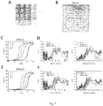
- Fig. 7A shows a 14 ⁇ 14 composite sequence formed by four-frequency 7 ⁇ 7 sequences, according to which four mixedly arranged unit cells are designed. The four unit cells correspond to four different frequencies.
- A, B, C, and D respectively represent unit cells designed on the basis of the four frequencies
- subscript numbers 0 to 6 represent seven phases
- Fig. 7B shows a sample photo of 14 ⁇ 14 unit cells
- Figs. 7C and 7D, and Figs. 7E and 7F show two multi-frequency ultra-thin Schroeder diffusers BMSD1 and BMSD2 designs.
- Coordinate axes of Fig. 7D and Fig. 7F mark that positions of the four designed frequencies relative to the center frequency are respectively as follows: 5772 Hz, 6860 Hz, 8153 Hz and 11517 Hz for BMSD1, and 6860 Hz, 8153 Hz, 9690 Hz and 11517 Hz for BMSD2.
- Figs. 7C and 7E show the unit cell parameters of four frequencies. The figures show the unit cells corresponding to different frequencies. Different ws need to be set to achieve expected phase distribution.
- Figs. 7D and 5F show diffuse reflection factors d 0, n and d 45, n at normal incidence and 45-degree incidence. Comparing the conventional Schroder diffuser (SD) with the ultra-thin Schroder diffuser (MSD) and multi-frequency ultra-thin Schroder diffuser (BMSD) results, it can be seen that the multi-frequency ultra-thin Schroeder diffuser can obtain a wider bandwidth and higher efficiency than that of the ultra-thin Schroeder diffuser.
- SD conventional Schroder diffuser
- MSD ultra-thin Schroder diffuser
- BMSD multi-frequency ultra-thin Schroder diffuser
Landscapes
- Physics & Mathematics (AREA)
- Engineering & Computer Science (AREA)
- Acoustics & Sound (AREA)
- Multimedia (AREA)
- Transducers For Ultrasonic Waves (AREA)
- Surface Acoustic Wave Elements And Circuit Networks Thereof (AREA)
- Physical Or Chemical Processes And Apparatus (AREA)
- Seasonings (AREA)
- Piezo-Electric Transducers For Audible Bands (AREA)
- Soundproofing, Sound Blocking, And Sound Damping (AREA)
Abstract
Description
- The invention relates to an ultra-thin Schroeder diffuser, and belongs to the field of acoustics.
- A conventional Schroeder acoustic structure is provided with multiple unit cells, and an opening width and a bottom width of the unit cell are uniform, resulting in a thicker thickness of the Schroeder acoustic structure, generally λ/2 , as shown in
Figs. 1 and 2 , which is not conducive to the integration of acoustic devices. - Object of the present invention: in order to overcome the deficiencies in the prior art, the present invention provides an ultra-thin Schroeder diffuser having a thickness of 1/10 of a conventional Schroeder diffuser and a smaller volume.
- Technical solutions: in order to achieve the above-mentioned object, the present invention discloses an ultra-thin Schroeder diffuser, which comprises a backing-plate, wherein the backing-plate is provided with 7 × p rows and 7 × q columns of unit cells, p and q are integers greater than or equal to 1, a side length of the square unit cell is 0.48λ, a depth of the square unit cell is 0.04λ, the unit cell is provided with a square neck, a side length of the square neck is less than the side length of the unit cell, a depth of the neck is 0.01λ, λ is a wavelength of the diffuser corresponding to the design at a center frequency f 0, the neck widths w of different unit cells are different, and a distribution of the widths satisfies a certain sequence, so that expected phase distribution is achieved in the center frequency or multiple frequencies around the center frequency. A final diffuse reflection effect can be achieved within a certain bandwidth around the center frequency f 0.
- Preferably, the p is 2, and the q is 2.
- Preferably, the backing-plate has an acoustic impedance of at least 100 times an acoustic impedance of air. A certain center frequency f 0 needs to be selected when setting the diffuser. Center positions of two adjacent unit cells are spaced by λ/2. The diffuser can be designed as single frequency and multi-frequency Schroder diffusers. A unit phase response of the single frequency diffuser is designed for the center frequency f 0. The multi-frequency Schroeder diffuser is designed with mixedly arranged unit cells for multiple frequencies around the center frequency f 0 to achieve more broadband diffuse reflection.
- Preferably, a target frequency of four is selected for the multi-frequency Schroeder diffuser. Beneficial effects: the invention can implement broadband sound wave diffuse reflection, has a comparable performance of diffuse reflection to the conventional Schroeder diffusers, and can reduce a material thickness in the meanwhile; the thickness of the invention is λ/20 only in comparison to a conventional Schroeder thickness λ/2, which is convenient to use in practice.
-
-
Fig. 1 shows a structural schematic diagram of a conventional Schroeder diffuser. -
Fig. 2 shows a structural schematic diagram of unit cells inFig. 1 . -
Fig. 3 shows a structural schematic diagram of a single period of the present invention. -
Fig. 4 shows a structural schematic diagram of unit cells inFig. 3 . -
Fig. 5 shows a design flow of the present invention and a photograph of a sample when p = 2,q = 2 -
Fig. 6 shows numerical simulation and experimental results of the ultra-thin Schroeder diffuser (MSD). -
Fig. 7 shows a design flow and numerical simulation and experimental results of a multi-frequency ultra-thin Schroeder diffuser (BMSD). - The present invention is further explained with reference to the drawings hereinafter.
- As shown in
Fig. 3 andFig. 4 , an ultra-thin Schroeder unit is an ultra-thin acoustic unit cell, a thinness of which is λ/20 only, and a width thereof is the same as that of a conventional Schroeder unit cell. The unit cell structure is as shown inFig. 4 . A neck and a bottom of the unit cell have different widths, the neck width is w, and the bottom width of the unit cell is 0.48λ, and a resonance effect of the acoustic unit cell produces the same acoustic attributes as that of the conventional unit cell structure, thus achieving the effects similar to the conventional Schroeder diffuser. Therefore, the phase response of the unit cell on the surface designed by us shall satisfy:
-
Fig. 5 shows a design of an ultra-thin Schroeder diffuser.Fig. 5A shows an analytical and simulated relationship between the phase shift and the geometrical parameter w. We control the phase shift of the unit cell by changing w. Triangles inFig. 5A show phases 2π × (0-6/7). These seven discrete phases provide seven values needed in a Schroeder sequence.Fig. 5B shows]7 × 7 unit cells,numbers 0 to 6 represent the phase response of seven cells corresponding to 2π × (0-6/7), which are corresponding to seven points inFig. 5A , and a final ultra-thin Schroeder diffuser sample can be designed through the sequence. -
Fig. 5C shows a top view of a sample that repeat 7 × 7 unit cells by a 2 × 2 (p = 2,q = 2) period, i.e., 14 × 14 unit cells. - Structural parameters: as an example, the sample is designed to have a working center frequency of f 0 = 6860Hz , and a sample size of 35cm × 35cm × 2.5cm . A value range of w is as shown in
Fig. 5A . In practical application, the sample size can be proportionally adjusted according to a working wavelength. - To quantitatively characterize a diffuse scattering effect, diffuse reflection coefficients can be defined as:


-
Fig. 6 shows numerical simulation and experimental results of an ultra-thin Schroeder diffuser. -
Fig. 6A shows reflection fields of the ultra-thin Schroeder diffuser (MSD) at normal incidence and 45-degree oblique incidence. Comparing the experimental (exp.) and simulation (sim.) results of the backing-plate inFig. 6B , the diffuse reflection effect of the ultra-thin Schroeder diffuser can be clearly seen.Fig. 6C shows that the samples at normal incidence and 45-degree incidence are consistent with the backing-plate directivity and acoustic pressure field results.Fig. 6D shows normalized diffuse reflection coefficients d 0,n and d 45,n of a conventional Schroeder diffuser (SD) and the ultra-thin Schroeder diffuser (MSD). It can be seen that the ultra-thin Schroeder diffuser can better simulate the diffuse reflection effect of the conventional Schroeder diffuser within about one octave around the center frequency f 0. In order to obtain a wider bandwidth, it is possible to design a unit cell for multiple frequencies to form a diffuser of mixedly arranged unit cells corresponding to different frequencies, as shown inFig. 7 , showing a design method for multi-frequency ultra-thin Schroeder diffuser (BMSD).Fig. 7A shows a 14 × 14 composite sequence formed by four-frequency 7 × 7 sequences, according to which four mixedly arranged unit cells are designed. The four unit cells correspond to four different frequencies. In the figure, A, B, C, and D respectively represent unit cells designed on the basis of the four frequencies,subscript numbers 0 to 6 represent seven phases, andFig. 7B shows a sample photo of 14 × 14 unit cells.Figs. 7C and 7D, and Figs. 7E and 7F show two multi-frequency ultra-thin Schroeder diffusers BMSD1 and BMSD2 designs. Coordinate axes ofFig. 7D and Fig. 7F mark that positions of the four designed frequencies relative to the center frequency are respectively as follows: 5772 Hz, 6860 Hz, 8153 Hz and 11517 Hz for BMSD1, and 6860 Hz, 8153 Hz, 9690 Hz and 11517 Hz for BMSD2.Figs. 7C and 7E show the unit cell parameters of four frequencies. The figures show the unit cells corresponding to different frequencies. Different ws need to be set to achieve expected phase distribution.Figs. 7D and5F show diffuse reflection factors d 0,n and d 45,n at normal incidence and 45-degree incidence. Comparing the conventional Schroder diffuser (SD) with the ultra-thin Schroder diffuser (MSD) and multi-frequency ultra-thin Schroder diffuser (BMSD) results, it can be seen that the multi-frequency ultra-thin Schroeder diffuser can obtain a wider bandwidth and higher efficiency than that of the ultra-thin Schroeder diffuser. - The descriptions above are merely preferable embodiments of the invention, and it should be noted that those of ordinary skills in the art may make a plurality of improvements and decorations without departing from the principle of the invention, and these improvements and decorations shall also fall within the protection scope of the invention.
Claims (4)
- An ultra-thin Schroeder diffuser, comprising a backing-plate, wherein the backing-plate is provided with 7 × p rows and 7 × q columns of unit cells, p and q are integers greater than or equal to 1, a side length of the square unit cell is 0.48λ, a depth of the square unit cell is 0.04λ, the unit cell is provided with a square neck, a side length of the square neck is less than the side length of the unit cell, a depth of the neck is 0.01λ, λ is a wavelength of the diffuser corresponding to the design at a center frequency f 0, and the neck widths w of different unit cells are different.
- The ultra-thin Schroeder diffuser according to claim 1, wherein the p is 2, and the q is 2.
- The ultra-thin Schroeder diffuser according to claim 1, wherein the backing-plate has an acoustic impedance of at least 100 times an acoustic impedance of air.
- The ultra-thin Schroeder diffuser according to claim 1, wherein center positions of two adjacent unit cells are spaced by λ/2.
Applications Claiming Priority (2)
| Application Number | Priority Date | Filing Date | Title |
|---|---|---|---|
| CN201610236484.9A CN105913837B (en) | 2016-04-15 | 2016-04-15 | An ultrathin Schroeder scatterer |
| PCT/CN2017/088403 WO2017177985A1 (en) | 2016-04-15 | 2017-06-15 | Ultra-thin schroeder diffuser |
Publications (1)
| Publication Number | Publication Date |
|---|---|
| EP3428914A1 true EP3428914A1 (en) | 2019-01-16 |
Family
ID=56746189
Family Applications (1)
| Application Number | Title | Priority Date | Filing Date |
|---|---|---|---|
| EP17781961.2A Withdrawn EP3428914A1 (en) | 2016-04-15 | 2017-06-15 | Ultra-thin schroeder diffuser |
Country Status (5)
| Country | Link |
|---|---|
| US (1) | US11120784B2 (en) |
| EP (1) | EP3428914A1 (en) |
| CN (1) | CN105913837B (en) |
| GB (1) | GB201902006D0 (en) |
| WO (1) | WO2017177985A1 (en) |
Cited By (1)
| Publication number | Priority date | Publication date | Assignee | Title |
|---|---|---|---|---|
| CN109949789A (en) * | 2019-04-16 | 2019-06-28 | 西南交通大学 | A frequency-variable sandwich thin-plate vibration-damping superstructure |
Families Citing this family (4)
| Publication number | Priority date | Publication date | Assignee | Title |
|---|---|---|---|---|
| CN105913837B (en) * | 2016-04-15 | 2019-09-13 | 南京大学 | An ultrathin Schroeder scatterer |
| CN106847255B (en) * | 2017-03-10 | 2020-06-16 | 南京大学 | Three-dimensional broadband Schroeder scatterer |
| CN106887224B (en) * | 2017-03-10 | 2021-03-19 | 南京大学 | A digital acoustic metamaterial |
| CN111171227B (en) * | 2020-01-07 | 2021-03-02 | 北京理工大学 | Underwater flexible Schroeder scatterer composite structure and preparation method thereof |
Family Cites Families (20)
| Publication number | Priority date | Publication date | Assignee | Title |
|---|---|---|---|---|
| US2703627A (en) * | 1954-04-16 | 1955-03-08 | Pittsburgh Corning Corp | Acoustic tile |
| US3180448A (en) * | 1962-01-02 | 1965-04-27 | Aerojet General Co | Laminated acoustic panel with sound absorbing cavities |
| JPS5939960B2 (en) * | 1976-09-03 | 1984-09-27 | ソニー株式会社 | speaker cabinet |
| JPS59181798A (en) * | 1984-03-14 | 1984-10-16 | Sony Corp | Loudspeaker cabinet |
| US4821839A (en) * | 1987-04-10 | 1989-04-18 | Rpg Diffusor Systems, Inc. | Sound absorbing diffusor |
| US5457291A (en) * | 1992-02-13 | 1995-10-10 | Richardson; Brian E. | Sound-attenuating panel |
| DE19804567C2 (en) * | 1998-02-05 | 2003-12-11 | Woco Franz Josef Wolf & Co Gmbh | Surface absorber for sound waves and use |
| KR100645824B1 (en) * | 2005-06-14 | 2006-11-14 | 김영옥 | Sound absorption panel |
| FR2929746B1 (en) * | 2008-04-07 | 2010-09-03 | Hutchinson | ACOUSTIC INSULATION PANEL |
| US8006802B2 (en) * | 2008-09-02 | 2011-08-30 | Yamaha Corporation | Acoustic structure and acoustic room |
| US7913813B1 (en) * | 2009-10-21 | 2011-03-29 | The Boeing Company | Noise shield for a launch vehicle |
| JP5771973B2 (en) * | 2010-05-17 | 2015-09-02 | ヤマハ株式会社 | Acoustic structure |
| EP2595142B1 (en) * | 2010-07-15 | 2021-01-20 | Aishin Kako Kabushiki Kaisha | Sound absorption characteristic structure |
| JP2013250501A (en) * | 2012-06-04 | 2013-12-12 | Three M Innovative Properties Co | Sound absorbing board |
| KR101422113B1 (en) * | 2013-04-26 | 2014-07-22 | 목포해양대학교 산학협력단 | Soundproof wall which has overlapped resonant chambers around air or water passage that makes air or water pass freely |
| GB201415874D0 (en) * | 2014-09-08 | 2014-10-22 | Sonobex Ltd | Acoustic Attenuator |
| CN105913837B (en) * | 2016-04-15 | 2019-09-13 | 南京大学 | An ultrathin Schroeder scatterer |
| WO2019203089A1 (en) * | 2018-04-18 | 2019-10-24 | 富士フイルム株式会社 | Soundproofing structure |
| US11043199B2 (en) * | 2018-04-25 | 2021-06-22 | Toyota Motor Engineering & Manufacturing North America, Inc. | Sparse acoustic absorber |
| US11929053B2 (en) * | 2019-09-11 | 2024-03-12 | The Hong Kong University Of Science And Technology | Broadband sound absorber based on inhomogeneous-distributed Helmholtz resonators with extended necks |
-
2016
- 2016-04-15 CN CN201610236484.9A patent/CN105913837B/en active Active
-
2017
- 2017-06-15 US US16/091,935 patent/US11120784B2/en active Active
- 2017-06-15 EP EP17781961.2A patent/EP3428914A1/en not_active Withdrawn
- 2017-06-15 WO PCT/CN2017/088403 patent/WO2017177985A1/en not_active Ceased
- 2017-06-15 GB GBGB1902006.4A patent/GB201902006D0/en not_active Ceased
Cited By (2)
| Publication number | Priority date | Publication date | Assignee | Title |
|---|---|---|---|---|
| CN109949789A (en) * | 2019-04-16 | 2019-06-28 | 西南交通大学 | A frequency-variable sandwich thin-plate vibration-damping superstructure |
| CN109949789B (en) * | 2019-04-16 | 2023-12-26 | 西南交通大学 | Frequency-variable sandwich sheet vibration reduction superstructure |
Also Published As
| Publication number | Publication date |
|---|---|
| US11120784B2 (en) | 2021-09-14 |
| CN105913837A (en) | 2016-08-31 |
| CN105913837B (en) | 2019-09-13 |
| GB201902006D0 (en) | 2019-04-03 |
| WO2017177985A1 (en) | 2017-10-19 |
| US20190130892A1 (en) | 2019-05-02 |
Similar Documents
| Publication | Publication Date | Title |
|---|---|---|
| US11120784B2 (en) | Ultra-thin Schroeder diffuser | |
| Zhu et al. | Reconfigurable origami-inspired metamaterials for controllable sound manipulation | |
| AU754279B2 (en) | Acoustic device comprising a panel member relying on bending wave action | |
| Li et al. | Three-dimensional vibration analysis of functionally graded material sandwich plates | |
| Gorman | Free in-plane vibration analysis of rectangular plates with elastic support normal to the boundaries | |
| Wang et al. | Harnessing geometric frustration to form band gaps in acoustic channel lattices | |
| CN111032107B (en) | Device for reducing the size of biological tissue | |
| US11574619B2 (en) | Acoustic structure for beaming soundwaves | |
| US20210049995A1 (en) | Directional sound device | |
| CN111180839A (en) | Broadband electromagnetic wave absorption structure based on frequency selective surface | |
| CN110912532A (en) | Method for regulating and controlling sound wave propagation path through boundary interception | |
| EP1271222A3 (en) | Reflection plate, manufacturing method thereof, liquid crystal display device and manufacturing method thereof | |
| CN106847255B (en) | Three-dimensional broadband Schroeder scatterer | |
| CN106887224B (en) | A digital acoustic metamaterial | |
| JP2011013356A5 (en) | ||
| Fujii et al. | Analysis of propagation characteristics of flexural wave in honeycomb sandwich panel and design of loudspeaker for radiating inclined sound | |
| CN118052001B (en) | Gradient Acoustic Metasurface Model | |
| US10475436B2 (en) | Hexagonal 2-dimensional reflection phase grating diffuser | |
| CN109036360B (en) | Voltage-withstanding acoustic filter for truncated parametric array and design method | |
| CN113901597A (en) | Gradient sawtooth-shaped metamaterial beam structure and beam/plate structure broadband vibration isolator | |
| JPH0887281A (en) | Two-dimensional primitive root diffuser | |
| CN109567744A (en) | Class skin matrix | |
| JP3413723B2 (en) | Architectural board | |
| Moghadasi et al. | Waveguide model for reflection phase characterization of periodic EBG surfaces | |
| Verdière et al. | Recent highlights on the parallel transfer matrix method (PTMM) |
Legal Events
| Date | Code | Title | Description |
|---|---|---|---|
| STAA | Information on the status of an ep patent application or granted ep patent |
Free format text: STATUS: THE INTERNATIONAL PUBLICATION HAS BEEN MADE |
|
| PUAI | Public reference made under article 153(3) epc to a published international application that has entered the european phase |
Free format text: ORIGINAL CODE: 0009012 |
|
| STAA | Information on the status of an ep patent application or granted ep patent |
Free format text: STATUS: REQUEST FOR EXAMINATION WAS MADE |
|
| 17P | Request for examination filed |
Effective date: 20181012 |
|
| AK | Designated contracting states |
Kind code of ref document: A1 Designated state(s): AL AT BE BG CH CY CZ DE DK EE ES FI FR GB GR HR HU IE IS IT LI LT LU LV MC MK MT NL NO PL PT RO RS SE SI SK SM TR |
|
| AX | Request for extension of the european patent |
Extension state: BA ME |
|
| STAA | Information on the status of an ep patent application or granted ep patent |
Free format text: STATUS: THE APPLICATION HAS BEEN WITHDRAWN |
|
| 18W | Application withdrawn |
Effective date: 20190315 |