EP3428902A1 - Image processing device, imaging device, mobile apparatus control system, image processing method, and program - Google Patents
Image processing device, imaging device, mobile apparatus control system, image processing method, and program Download PDFInfo
- Publication number
- EP3428902A1 EP3428902A1 EP17762735.3A EP17762735A EP3428902A1 EP 3428902 A1 EP3428902 A1 EP 3428902A1 EP 17762735 A EP17762735 A EP 17762735A EP 3428902 A1 EP3428902 A1 EP 3428902A1
- Authority
- EP
- European Patent Office
- Prior art keywords
- road surface
- image
- vertical direction
- unit
- unit configured
- Prior art date
- Legal status (The legal status is an assumption and is not a legal conclusion. Google has not performed a legal analysis and makes no representation as to the accuracy of the status listed.)
- Withdrawn
Links
Images





Classifications
-
- B—PERFORMING OPERATIONS; TRANSPORTING
- B60—VEHICLES IN GENERAL
- B60R—VEHICLES, VEHICLE FITTINGS, OR VEHICLE PARTS, NOT OTHERWISE PROVIDED FOR
- B60R21/00—Arrangements or fittings on vehicles for protecting or preventing injuries to occupants or pedestrians in case of accidents or other traffic risks
- B60R21/02—Occupant safety arrangements or fittings, e.g. crash pads
-
- G—PHYSICS
- G06—COMPUTING OR CALCULATING; COUNTING
- G06V—IMAGE OR VIDEO RECOGNITION OR UNDERSTANDING
- G06V20/00—Scenes; Scene-specific elements
- G06V20/50—Context or environment of the image
- G06V20/56—Context or environment of the image exterior to a vehicle by using sensors mounted on the vehicle
-
- B—PERFORMING OPERATIONS; TRANSPORTING
- B60—VEHICLES IN GENERAL
- B60R—VEHICLES, VEHICLE FITTINGS, OR VEHICLE PARTS, NOT OTHERWISE PROVIDED FOR
- B60R21/00—Arrangements or fittings on vehicles for protecting or preventing injuries to occupants or pedestrians in case of accidents or other traffic risks
-
- G—PHYSICS
- G06—COMPUTING OR CALCULATING; COUNTING
- G06T—IMAGE DATA PROCESSING OR GENERATION, IN GENERAL
- G06T1/00—General purpose image data processing
- G06T1/60—Memory management
-
- G—PHYSICS
- G06—COMPUTING OR CALCULATING; COUNTING
- G06T—IMAGE DATA PROCESSING OR GENERATION, IN GENERAL
- G06T7/00—Image analysis
-
- G—PHYSICS
- G08—SIGNALLING
- G08G—TRAFFIC CONTROL SYSTEMS
- G08G1/00—Traffic control systems for road vehicles
- G08G1/16—Anti-collision systems
-
- B—PERFORMING OPERATIONS; TRANSPORTING
- B60—VEHICLES IN GENERAL
- B60R—VEHICLES, VEHICLE FITTINGS, OR VEHICLE PARTS, NOT OTHERWISE PROVIDED FOR
- B60R21/00—Arrangements or fittings on vehicles for protecting or preventing injuries to occupants or pedestrians in case of accidents or other traffic risks
- B60R2021/003—Arrangements or fittings on vehicles for protecting or preventing injuries to occupants or pedestrians in case of accidents or other traffic risks characterised by occupant or pedestian
-
- B—PERFORMING OPERATIONS; TRANSPORTING
- B60—VEHICLES IN GENERAL
- B60R—VEHICLES, VEHICLE FITTINGS, OR VEHICLE PARTS, NOT OTHERWISE PROVIDED FOR
- B60R21/00—Arrangements or fittings on vehicles for protecting or preventing injuries to occupants or pedestrians in case of accidents or other traffic risks
- B60R21/01—Electrical circuits for triggering passive safety arrangements, e.g. airbags, safety belt tighteners, in case of vehicle accidents or impending vehicle accidents
- B60R2021/01204—Actuation parameters of safety arrangents
- B60R2021/01252—Devices other than bags
- B60R2021/01259—Brakes
Definitions
- the disclosures discussed herein relate to an image processing apparatus, an imaging device, a moving body device control system, an image processing method, and a program.
- An object recognition technique for recognizing an object such as a person or another vehicle by performing the following image processing is known in the related art, in measurement using images captured by such a stereo camera (see, e.g., Patent Document 1).
- a V-Disparity image is generated with a vertical coordinate of an image as one axis, disparity of the image as the other axis, and a value of disparity frequency as a pixel value, from a plurality of images captured by a stereo camera.
- a road surface is detected from the generated V-Disparity image.
- a U-Disparity image is generated with a horizontal coordinate of an image as a vertical axis, parallax of the image as the horizontal axis, and the disparity frequency as the pixel value.
- an object such as a person or another vehicle is recognized based on the generated U-Disparity image.
- Patent Document 1 Japanese Unexamined Patent
- noise is generated in parallax due to reflection of a road surface in rainy weather and the road surface is unable to be accurately measured.
- an image processing apparatus includes a generation unit configured to generate vertical direction distribution data indicating a frequency distribution of distance values with respect to a vertical direction of a range image, from the range image having distance values according to distance of a road surface in a plurality of captured images captured by a plurality of imaging parts; an extraction unit configured to set a search range corresponding to a predetermined reference point in the vertical direction distribution data and extract a plurality of pixels from the search range; and a detection unit configured to detect a road surface, based on the plurality of extracted pixels.
- the following illustrates a moving body device control system having an image processing apparatus according to an embodiment.
- FIG. 1 is a diagram illustrating a configuration of an in-vehicle device control system acting as a moving body device control system, according to an embodiment of the present invention.
- the in-vehicle device control system 1 is installed in a reference vehicle 100 such as an automobile that is a moving body.
- the in-vehicle device control system 1 includes an imaging unit 500, an image analysis unit 600, a display monitor 103, and a vehicle traveling control unit 104.
- the in-vehicle device control system 1 detects relative height information (information indicating relative inclination condition) of a road surface (moving body traveling surface) ahead of the reference vehicle, from image data each having an image of a forward region of the moving body in a reference vehicle traveling direction (imaging region) obtained by the imaging unit 500, detects a three-dimensional shape of the traveling road surface ahead of the reference vehicle from the detection result of the relative height information, and controls the moving body and various in-vehicle devices using the detection result of the three-dimensional shape of the traveling road surface.
- the control of the moving body includes, for example, transmission of alert signs, control of a steering wheel of the reference vehicle 100 (reference moving body), or braking of the reference vehicle 100 (the reference moving body).
- the imaging unit 500 is disposed in the vicinity of a rear-view mirror (not illustrated) of a windshield 105 of the reference vehicle 100.
- Various data such as captured image data obtained by the imaging unit 500 are input into the image analysis unit 600 acting as an image processing unit.
- the image analysis unit 600 analyzes data transmitted from the imaging unit 500, detects a relative height (positional information) at each point on a road surface ahead of the reference vehicle with respect to a road surface portion (a road surface portion directly beneath the reference vehicle) on which the reference vehicle 100 is traveling, and obtains a three-dimensional shape of the (moving body) traveling road surface ahead of the reference vehicle. Further, the image analysis unit 600 recognizes recognition target objects such as other vehicles, pedestrians, various obstacles, etc., ahead of the reference vehicle.
- the analysis results of the image analysis unit 600 are sent to the display monitor 103 and the vehicle traveling control unit 104.
- the display monitor 103 displays captured image data obtained by the imaging unit 500 and analysis results.
- the vehicle traveling control unit 104 may, for example, send an alert sign to a driver of the reference vehicle 100 or perform traveling support control such as control of the steering wheel and braking of the reference vehicle, based on the recognition results of a recognition target object obtained by the image analysis unit 600, such as another vehicle, pedestrian, and various obstacles ahead of the vehicle.
- FIG. 2 is a diagram illustrating configurations of the imaging unit 500 and the image analysis unit 600 according to an embodiment.
- the imaging unit 500 includes a stereo camera having two imaging parts 510a and 510b as imaging units.
- the two imaging parts 510a and 510b are the same components.
- the imaging parts 510a and 510b include imaging lenses 511a and 511b, sensor substrates 514a and 514b including image sensors 513a and 513b having two-dimensionally arranged light receiving elements, and signal processors 515a and 515b configured to generate and output captured image data obtained by converting analog electric signals output from the sensor substrates 514a and 514b (electric signals corresponding to amounts of light received by respective light receiving elements on the image sensors 513a and 513b) into digital electric signals.
- the imaging unit 500 outputs luminance image data and parallax image data.
- the imaging unit 500 includes a process hardware unit 510 including a Field-Programmable Gate Array (FPGA) or the like.
- the process hardware unit 510 includes a disparity calculation unit 511 as a parallax image information generation unit to calculate a disparity value of a corresponding image portion between the respective captured images captured by the imaging parts 510a and 510b.
- the disparity value referred to in this case is a value obtained by taking one of the captured images captured by the imaging parts 510a and 510b as a reference image, and the other one as a comparison image, and calculating a positional deviation corresponding to a same point within the imaging region of an image portion on the comparison image with respect to an image portion on the reference image, as a disparity value of the image portion.
- a distance to the same point within an imaging region corresponding to the image portion may be calculated based on the disparity value of the image portion.
- the image analysis unit 600 is configured to include an image processing board or the like; the image analysis unit 600 includes a storage unit 601 having a RAM, a ROM or the like configured to store the luminance image data and the parallax image data output from the imaging unit 500, a central processing unit (CPU) 602 configured to execute a computer program for performing disparity calculation control and the like, a data interface (I/F) 603, and a serial I/F 604.
- a storage unit 601 having a RAM, a ROM or the like configured to store the luminance image data and the parallax image data output from the imaging unit 500
- CPU central processing unit
- I/F data interface
- the FPGA constituting the process hardware unit 510 executes a process requiring real-time processing on image data, for example, gamma correction, distortion correction (parallelization of left and right captured images), and disparity calculation by block matching to generate parallax images and write the generated information in the RAM of the image analysis unit 600.
- the CPU of the image analysis unit 600 is responsible for control of an image sensor control unit of each of the imaging parts 510a and 510b and overall control of the image processing board.
- the CPU of the image analysis unit 600 also loads a program for executing a process of detecting a three-dimensional shape of a road surface, a process of detecting various objects (objects) such as guardrails, and the like from the ROM, executes various kinds of processes by inputting the luminance image data and the parallax image data stored in the RAM, and outputs the process results to the outside from the data I/F 603 and the serial I/F 604.
- vehicle operation information such as vehicle velocity and acceleration (mainly acceleration in a longitudinal direction of the vehicle), steering angle, and yaw rate of the reference vehicle 100, is input via the data I/F 603, and used as parameters of various kinds of processes.
- the data output to the outside may be used as input data for controlling the various devices of the reference vehicle 100 (brake control, vehicle velocity control, warning control, etc.).
- imaging unit 500 and the image analysis unit 600 may integrally form an imaging device 2, as an integrated device.
- FIG. 3 is a functional block diagram of an in-vehicle device control system 1 implemented by the process hardware unit 510, the image analysis unit 600, and the vehicle traveling control unit 104 in FIG. 2 .
- a functional unit implemented by the image analysis unit 600 is implemented by a process executed by the CPU 602 of the image analysis unit 600 by one or more programs installed in the image analysis unit 600.
- a parallax image generation unit 11 performs a parallax image generation process for generating parallax image data (parallax image information). Note that the parallax image generation unit 11 is constituted by, for example, a disparity calculation unit 511 ( FIG. 2 ).
- the parallax image generation process includes, first, setting the luminance image data of one imaging part 510a of the two imaging parts 510a and 510b as reference image data, setting the luminance image data of the other imaging part 510b as comparison image data, calculating disparity between the two sets of the luminance image data, generating parallax image data based on the calculated disparity, and outputting the generated parallax image data.
- the parallax image data indicates a parallax image including respective image portions with respective pixel values according to disparities d calculated for respective image portions on the reference image data.
- the parallax image generation unit 11 defines a block including a plurality of pixels (e.g., 16 pixels ⁇ 1 pixel) having one target pixel in the center with respect to a certain row of the reference image data.
- a correlation value which indicates a correlation between a feature quantity indicating a feature of pixel values of a block defined in the reference image data and a feature quantity indicating a feature of pixel values of a corresponding block in the comparison image data, is calculated by shifting a block having the same size as the block of the defined reference image data pixel by pixel in the horizontal line direction (x direction).
- a matching process is performed to select a block of the comparison image data having the highest correlation with the block of the reference image data from among the blocks in the comparison image data. Thereafter, the positional deviation between the target pixel of the block of the reference image data and the corresponding pixel of the block of the comparison image data selected by the matching process is calculated as a disparity value d.
- the parallax image data may be obtained by performing such a process of calculating a disparity value d on the entire region or a specific region of the reference image data.
- a value (luminance value) of each pixel within a block may be used, for example.
- the correlation value the sum of the absolute values of the difference between the value (luminance value) of each of pixels in the block of the reference image data and the value (luminance value) of a corresponding one of pixels in the block of the comparison image data may be used, for example. In this case, the block having the smallest sum has the highest correlation.
- the road surface estimation unit 12 estimates (detects) a road surface, based on a parallax image generated by the parallax image generation unit 11.
- FIG. 4 is a functional block diagram of the road surface estimation unit 12.
- the road surface estimation unit 12 includes a V-map generation unit 121, a sample point extraction unit 122, an outlier removal unit 123, a road surface shape detection unit 124, a road surface complement unit 125, a smoothing process unit 126, and a road surface height table calculation unit 127.
- the V-map generation unit 121 executes a V-map generation process for generating a V-map (a V-Disparity Map, an example of "vertical direction distribution data”), based on parallax pixel data.
- Each parallax pixel data included in the parallax image data is indicated by a set (x, y, d) of an x direction position, a y direction position, and a disparity value d.
- the parallax pixel data that is transformed into three-dimensional coordinate information (d, y, f), where d is set on the X axis, y is set on the Y axis, and frequency f is set on the Z axis may be generated as parallax histogram information.
- three dimensional coordinate information (d, y, f) that is limited to information exceeding a predetermined frequency threshold value from this three-dimensional coordinate information (d, y, f) may be generated as parallax histogram information.
- the parallax histogram information of the present embodiment includes three-dimensional coordinate information (d, y, f), and this three-dimensional histogram information distributed in the XY two-dimensional coordinate system is referred to as a V-map (V-disparity map).
- the V-map generation unit 121 calculates disparity value frequency distribution for each row region of the parallax image data obtained by dividing a parallax image into multiple parts in a vertical direction.
- the information indicating the disparity value frequency distribution is parallax histogram information.
- FIGS. 5A and 5B are diagrams illustrating parallax image data and a V-map generated from the parallax image data.
- FIG. 5A is a diagram illustrating an example of disparity value distribution of a parallax image
- FIG. 5B is a diagram illustrating a V-map indicating the disparity value frequency distribution by each row of the parallax image in FIG. 5A .
- the V-map generation unit 121 calculates a disparity value frequency distribution that is a distribution of the number of data sets for each disparity value per row, and outputs the calculated disparity value frequency distribution as parallax histogram information.
- a V-map as illustrated in FIG. 5B may be obtained by representing information on the disparity value frequency distribution for each row obtained in this manner on a two-dimensional orthogonal coordinate system, where a y-direction position (vertical position of the captured image) on the parallax image is taken on the Y-axis and the disparity value is taken on the X-axis.
- the V-map may be expressed as an image in which pixels having pixel values according to the frequency f are distributed on the two-dimensional orthogonal coordinate system.
- FIGS. 6A and 6B are diagrams illustrating an example of a captured image as a reference image captured by one imaging part, and an example of a V-map corresponding to the captured image in FIG. 6A , respectively.
- FIG. 6A depicts the captured image
- FIG. 6B depicts the V-map. That is, the V-map illustrated in FIG. 6B is generated from the captured image as illustrated in FIG. 6A .
- no parallax is detected in a region below the road surface, and the parallax is not counted in a shaded region A.
- FIG. 6A depicts a road surface 401 on which the reference vehicle is traveling, a preceding vehicle 402 existing ahead of the reference vehicle, and a utility pole 403 existing off the road.
- the V-map in FIG. 6B depicts a road surface 501, a preceding vehicle 502, and a utility pole 503 corresponding to the example of the image of FIG. 6A .
- a relatively flat road surface of the road surface ahead of the reference vehicle 100 matches a virtual reference road surface (virtual reference traveling surface).
- a road surface ahead of the reference vehicle 100 which extends parallel to a road surface portion directly beneath the reference vehicle 100 toward a frontward direction of the reference vehicle, matches a virtual reference road surface (virtual reference traveling surface).
- high frequency points the road surface 501 are distributed in a substantially linear manner with the inclination such that the disparity value d decreases toward the upper part of the image.
- Pixels indicating such distribution are present at approximately the same distance in each row on the parallax image, have the highest occupancy rate, and furthermore reflect a detection target having a distance becoming continuously farther toward the upper part of the image.
- the imaging part 510a captures an image in a forward region of the reference vehicle, and content of the captured image indicates, as illustrated in FIG. 6B , that the disparity value d of the road surface decreases toward the upper part of the image in FIG. 6A .
- the pixels displaying the road surface have substantially the same disparity value d within the same row (horizontal line).
- the high frequency points (road surface 501) distributed in a substantially linear manner on the V-map correspond to the features of the pixels that display the road surface (vehicle traveling surface).
- pixels of points distributed on or near an approximate straight line obtained by linear approximation of high frequency points on the V-map may be estimated as pixels reflecting the road surface with high accuracy.
- the distance to the road surface portion displayed in each pixel may be obtained with high accuracy from the disparity value d of the corresponding point on the approximate straight line.
- the V-map generation unit 121 may generate a V-map using only pixels in a predetermined region (e.g., a region that may reflect a road surface) in a parallax image, or may generate a V-map using all the pixels in the parallax image.
- a predetermined region e.g., a region that may reflect a road surface
- FIGS. 7A and 7B are diagrams illustrating an example of a captured image as a reference image captured by one imaging part when noise is generated, and an example of a V-map corresponding to the captured image, respectively.
- FIGS. 7A and 7B a reflected light 404 from a puddle or the like is depicted in FIG. 7A , compared to the examples of FIG. 6A and FIG. 6B , respectively. Further, a reflected light 504 from a puddle or the like is presented in the V-map depicted in FIG. 7B .
- FIGS. 7A and 7B when reflected light is generated, erroneous matching or the like occurs for calculating disparity even with parallax on the same road surface. As a result, a disparity value diffing from the original disparity will be calculated. In such a case, the parallax of the road surface is dispersed in the lateral (horizontal) direction as 504 in FIG. 7B .
- the sample point extraction unit 122 extracts sample points used for estimating a road surface from a V-map generated by the V-map generation unit 121.
- the V-map is divided into a plurality of segments according to a disparity value (i.e., a distance value from the reference vehicle), and the sample point extraction process, the road surface shape detection process, and the like described later are performed.
- a disparity value i.e., a distance value from the reference vehicle
- the sample point extraction process, the road surface shape detection process, and the like may be performed without dividing the V-map.
- FIG. 8 is a flowchart illustrating an example of the sample point extraction process.
- the sample point extraction unit 122 divides a V-map into a plurality of segments according to disparity values corresponding to the horizontal axis of the V-map (step S1).
- the sample point extraction unit 122 sets a range (search range) for searching for a sample point to be extracted in a segment (first segment) having the largest disparity value (the closest distance from the reference vehicle) (step S2).
- FIG. 9 is a diagram illustrating an example of a process of extracting sample points from a first segment.
- the sample point extraction unit 122 determines, for example, a start point position 552 of a straight line corresponding to a default road surface 551 ("preset road surface") as a reference point, and sets a predetermined range corresponding to the reference point as a sample point search region 553.
- the data on the default road surface is preset, for example, when a stereo camera is attached to the reference vehicle. For example, data on a flat road surface may be set.
- the sample point extraction unit 122 may determine a search region 553 to be an interval between two straight lines 554 and 555 extending from the reference point acting as a start point to an adjacent segment at a predetermined angle.
- the sample point extraction unit 122 may determine the two straight lines 554 and 555 in accordance with an angle at which the road surface is allowed to be inclined.
- the sample point extraction unit 131 may determine the lower straight line 554 with respect to inclination of a downhill road surface that may be captured by the stereo camera, and may determine the upper straight line 555 with respect to the upper limit of inclination of an uphill road surface prescribed by law or the like.
- the sample point extraction unit 122 may set the search region 553 to be, for example, a rectangular region.
- the sample point extraction unit 122 extracts a sample point from among pixels included in the search range (step S3).
- the sample point extraction unit 122 may extract one or more sample points from among the pixels included in the search range, for example, for each of coordinate positions of disparity values d.
- the sample point extraction unit 122 may extract the most frequently occurring point indicating the highest frequency (mode) at a coordinate position of each disparity value d as a sample point from among the pixels included in the search range.
- the sample point extraction unit 122 may extract, from among the pixels included in the search range, the most frequently occurring point indicating the highest frequency (mode) at a plurality of coordinate positions including a disparity value d (e.g., the coordinate position of each disparity value d and one or more coordinate positions of at least left or right of the disparity value d) as a sample point.
- a disparity value d e.g., the coordinate position of each disparity value d and one or more coordinate positions of at least left or right of the disparity value d
- the outlier removal unit 123, the road surface shape detecting unit 124, and the road surface complement unit 125 detect a road surface in the segment including the sample points, based on the sample points extracted in step S3 (step S4).
- the sample point extraction unit 122 determines whether there is a next segment (e.g., a segment having the next smallest disparity value) (step S5), and when there is no next segment (NO in step S5), the sample point extraction unit 131 ends the process.
- a next segment e.g., a segment having the next smallest disparity value
- step S5 When there is a next segment (YES in step S5), the sample point extraction unit 122 acquires an end point position of the road surface detected in step S4 (step S6).
- the sample point extraction unit 122 sets a search range, based on the end point position of the road surface acquired in step S5 (step S7), and proceeds to a process in step S3.
- FIGS. 10A and 10B are diagrams illustrating an example of a process of extracting sample points from a second segment other than the first segment.
- the sample point extraction unit 122 sets an end point position (a position at which the road surface 561 of the previous segment contacts the second segment) of the road surface 561 of the previous segment (a segment adjacent to the second segment and from which the road surface has been already detected) as a reference point 562.
- the sample point extraction unit 122 sets a predetermined range corresponding to the reference point 562 as a sample point search region 563.
- the sample point extraction unit 122 may determine a search region 563 to be an interval between two straight lines 564 and 565 extending from the reference point acting as a start point to an adjacent segment at a predetermined angle. In this case, the sample point extraction unit 122 may determine the two straight lines 564 and 565 in accordance with an angle at which the road surface may be inclined. Alternatively, the sample point extraction unit 122 may set the search region 563 to be a rectangular region having a height corresponding to the y coordinate of the reference point 562, as illustrated in FIG. 10B .
- FIG. 11 is a diagram illustrating another example of a process of extracting sample points from the second segment.
- the sample point extraction unit 122 sets an end point position of a road surface (history road surface) 561a of the segment adjacent to the second segment detected in a frame of the previous parallax image as a reference point 562a. Then, the sample point extraction unit 122 sets a predetermined range corresponding to the reference point 562a as a sample point search region 563a.
- a more appropriate search range may be set compared with the case where the end point position of the road surface is set as the reference point as illustrated in FIGS. 10A and 10B .
- the road surface detected in one previous frame may be used, or the average of the road surfaces detected in the plurality of previous frames may be used.
- the outlier removal unit 123 removes a sample point that is not suitable for linear approximation from among the sample points extracted by the sample point extraction unit 122.
- FIG. 12 is a flowchart illustrating an example of an outlier removal process.
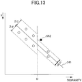
- FIG. 13 is a diagram illustrating a process of removing an outlier.
- the outlier removal unit 123 calculates an approximate straight line from the sample points of each segment extracted by the sample point extraction unit 122 or from the sample points of all segments (step S20).
- the outlier removal unit 123 calculates an approximate straight line using, for example, a least squares method.
- the approximate straight line 541 is calculated in step S20 in FIG. 12 .
- the outlier removal unit 123 calculates a threshold value according to a value of an X coordinate (step S21).
- a predetermined X coordinate value D e.g., a disparity value corresponding to a distance of 50 m from the reference vehicle
- a predetermined value 2o is set to X coordinate values less than the predetermined X coordinate value D (a predetermined distance farther from the reference vehicle)
- a predetermined value ⁇ is set to X coordinate values having the predetermined X coordinate value D or more (a predetermined distance or less from the reference vehicle).
- the outlier removal unit 123 removes a sample point having the Euclidean distance being equal to or greater than the threshold value calculated in step S21 with respect to the calculated approximate straight line (step S22).
- the sample point 542 having an X coordinate value equal to or greater than D and being separated by a predetermined threshold ⁇ or more is removed.
- ⁇ may be set in two or more places, and ⁇ may be calculated and set as a function of disparity d.
- the road surface shape detection unit 124 detects a shape (position, height) of the road surface from each segment of the V-map generated by the V-map generation unit 121, based on the sample points extracted by the sampling point extraction unit 122 and not removed by the outlier removal unit 123.
- the road surface shape detection unit 124 calculates an approximate straight line from the sample points of each segment, for example, by a least squares method, and detects (estimates) the calculated approximate straight line as a road surface.
- the road surface complement unit 125 determines whether the road surface detected (estimated) by the road surface shape detection unit 124 is inappropriate. When the road surface complement unit 125 determines that the detected road surface is inappropriate, the road surface complement unit 125 complements the road surface. The determination as to whether the detected road surface is inappropriate may be made based on not only the determination on the angle of the road surface but also a case where the score used for the estimation is smaller than a predetermined threshold value or a case where the correlation coefficient when approximating by the least squares method is smaller than a predetermined value (when the point group variability is large).
- the road surface complement unit 125 determines whether an inappropriate road surface that is impossible to be captured by a stereo camera has been estimated due to noise. When the road surface complement unit 125 determines that an inappropriate road surface has been estimated, the road surface complement unit 125 complements (interpolates) the inappropriate road surface, based on a default road surface or road surface data estimated in the previous frames.
- the road surface road surface complement unit 125 assumes that the road surface is a downhill slope with a steep gradient as the distance from the reference vehicle increases. Then, the road surface complement unit 125 removes the data of the road surface and complements the removed road surface data with data such as a default road surface instead.
- the smoothing process unit 126 corrects a road surface estimated in each segment such that the estimated road surfaces are continuous.
- the smoothing process unit 126 changes inclination and intercept of each of the road surfaces such that an end point (endpoint) of one of the road surfaces estimated in the two adjacent segments matches a start point (endpoint) of the other road surface.
- the road surface height table calculation unit 127 performs a road surface height table calculation process of calculating a road surface height (a relative height with respect to the road surface portion directly beneath the reference vehicle), based on the road surface in each segment corrected by the smoothing process unit 126, and converting calculated results into a table.
- the road surface height table calculation unit 127 calculates a distance to each road surface portion displayed in each row region (each position in the vertical direction of an image) on the captured image from information on the road surface in each segment. It is predetermined which row region in the captured image is to display each road surface portion in a vehicle traveling direction of a virtual plane, which is obtained by extending a road surface portion located directly beneath the reference vehicle in a forward traveling direction of the reference vehicle in parallel with the road surface portion. This virtual plane (reference road surface) is represented by a straight line (reference straight line) on the V-map.
- the road surface height table calculation unit 127 may obtain the height of each road surface portion ahead of the reference vehicle by comparing the road surface in each segment with the reference straight line.
- the road surface height table calculation unit 127 may simply calculate the height of the road surface portion existing ahead of the reference vehicle by the distance from the Y axis position on the road surface in each segment obtained from the corresponding disparity value.
- the road surface height table calculation unit 127 tabulates the height of each road surface portion obtained from the approximate straight line with respect to the necessary disparity range.
- the height of an object displayed on the captured image portion corresponding to a certain point where the Y axis position is y' at a disparity value d from the road surface may be calculated from (y'-y0) when the Y-axis position on the road surface at the disparity value d is y0.
- the height H of the object corresponding to the coordinates (d, y') on the V-map from the road surface may be calculated from the following formula.
- "f” is a value obtained by converting a focal distance of a camera into the same unit as that of (y'-Y0).
- BF is a value obtained by multiplying the baseline length of a stereo camera by the focal length
- offset is a disparity value when an object at infinity is imaged.
- a clustering unit 13 generates XY two-dimensional histogram information (frequency U-map) by setting a set (x, y, d) of x being an x direction position, y being a y direction position, and d being a parallax value d in each parallax pixel data included in the parallax image data, such that x is set on the X axis, d is set on the Y axis, and the frequency is set on the Z axis.
- the clustering unit 13 generates a frequency U-map only for the points (x, y, d) of the parallax image in which the height H from the road surface is within a predetermined height range (e.g., 20 cm to 3 m), based on the height of each road surface portion tabulated by the road surface height table calculation unit 127. In this case, it is possible to appropriately extract an object existing in the predetermined height range from the road surface.
- a predetermined height range e.g. 20 cm to 3 m
- the clustering unit 13 detects, as an object region, a region where the frequency is greater than a predetermined value and the parallax is dense, and assigns, to the object region, individual information, such as coordinates on the parallax image and a type (human or pedestrian) of an object predicted from the actual size (size) of the object.
- the rejection unit 14 rejects information on an object that is not a recognition target based on the parallax image, the frequency U-map, and the individual information of the object.
- a tracking unit 15 determines whether the detected object is a tracking target when the detected object appears consecutively in frames of a plurality of parallax images.
- a control unit 139 may, for example, send an alert sign to a driver of the reference vehicle 100 or perform traveling support control (driving support control) such as control of the steering wheel and braking of the reference vehicle, based on the detection result of the object by the clustering unit 13.
- traveling support control driving support control
- an estimated road surface When noise is generated in parallax due to reflection of the road surface during rainy weather, an estimated road surface may be too low or too high with respect to the correct road surface. When the estimated road surface is too low, a part of the road surface may be erroneously recognized as an obstacle. When the estimated road surface is too high, an obstacle or the like lower than the estimated road surface will not be detected in some cases.
- a search range corresponding to a predetermined reference point is set, a plurality of pixels are extracted from the search range, and a road surface is detected based on the extracted plurality of pixels. This makes it possible to improve the accuracy of detecting a road surface.
- a parallax image is used as an example of a range image in the present embodiments; however, the present invention is not limited to this example.
- a range image may be generated by integrating distance information generated by using a detection device such as millimeter wave radar or laser radar with respect to a parallax image generated by using a stereo camera.
- a combination of a stereo camera and a detection device such as millimeter wave radar or laser radar may combine a detection result of an object obtained by the detection device with the detection result of the object obtained by the above-described stereo camera to further improve detection accuracy.
- system configuration in the above-described embodiments is merely an example, and various examples of the system configuration may also be applied according to intended use and purposes.
- the system configuration may exclude these functional units.
- respective functional units of the process hardware unit 510, the image analysis unit 600, and the vehicle traveling control unit 104 may be implemented by hardware, or may be implemented by a CPU executing a program stored in a storage device.
- the above-described program may be distributed in a form of a computer-readable recording medium storing the program in files of an installable format or executable format.
- the recording medium may include a compact disc recordable (CD-R), a digital versatile disk (DVD), and a Blu-ray Disc.
- CD-R compact disc recordable
- DVD digital versatile disk
- Blu-ray Disc Blu-ray Disc
Landscapes
- Engineering & Computer Science (AREA)
- Physics & Mathematics (AREA)
- General Physics & Mathematics (AREA)
- Theoretical Computer Science (AREA)
- Mechanical Engineering (AREA)
- Computer Vision & Pattern Recognition (AREA)
- Multimedia (AREA)
- Image Analysis (AREA)
- Traffic Control Systems (AREA)
- Image Processing (AREA)
Abstract
Description
- The disclosures discussed herein relate to an image processing apparatus, an imaging device, a moving body device control system, an image processing method, and a program.
- In vehicle safety, automobile body structures and the like have been developed from the perspectives of pedestrian and passenger protection against collision with pedestrians and other automobiles. Recent advances in information processing and image processing technologies have led to the development of high rate detection techniques for detecting people, automobiles, etc. Automobiles applied with these technologies are already on sale; such automobiles automatically apply brakes before collision in order to prevent collision.
- In order to apply brakes automatically, measuring a distance between an automobile and an object such as a person, another automobile, etc. is mandatory; hence, measurement using images of stereo cameras has been put into practical use for that reason.
- An object recognition technique for recognizing an object such as a person or another vehicle by performing the following image processing is known in the related art, in measurement using images captured by such a stereo camera (see, e.g., Patent Document 1).
- According to this technique, first, a V-Disparity image is generated with a vertical coordinate of an image as one axis, disparity of the image as the other axis, and a value of disparity frequency as a pixel value, from a plurality of images captured by a stereo camera. Next, a road surface is detected from the generated V-Disparity image. After removing noise using the detected road surface, a U-Disparity image is generated with a horizontal coordinate of an image as a vertical axis, parallax of the image as the horizontal axis, and the disparity frequency as the pixel value. Then, an object such as a person or another vehicle is recognized based on the generated U-Disparity image.
- [Patent Document 1] Japanese Unexamined Patent
- Application Publication No.
2015-075800 - However, in the related art technique, noise is generated in parallax due to reflection of a road surface in rainy weather and the road surface is unable to be accurately measured.
- Thus, it is an object to provide a technique for improving the accuracy of detecting a road surface.
- According to an aspect of the disclosure, an image processing apparatus includes
a generation unit configured to generate vertical direction distribution data indicating a frequency distribution of distance values with respect to a vertical direction of a range image, from the range image having distance values according to distance of a road surface in a plurality of captured images captured by a plurality of imaging parts;
an extraction unit configured to set a search range corresponding to a predetermined reference point in the vertical direction distribution data and extract a plurality of pixels from the search range; and
a detection unit configured to detect a road surface, based on the plurality of extracted pixels. - According to the disclosed technique, it is possible to improve the accuracy of detecting a road surface.
-
-
FIG. 1 is a schematic diagram illustrating a configuration of an in-vehicle device control system, according to an embodiment; -
FIG. 2 is a schematic diagram illustrating configurations of an imaging unit and an image analysis unit, according to an embodiment; -
FIG. 3 is a functional block diagram illustrating a moving body device control system, according to an embodiment; -
FIG. 4 is a functional block diagram of a road surface estimation unit; -
FIG. 5A is a diagram illustrating parallax image data and a V-map generated from the parallax image data; -
FIG. 5B is a diagram illustrating parallax image data and a V-map generated from the parallax image data; -
FIG. 6A is a diagram illustrating an example of a captured image as a reference image captured by one imaging part; -
FIG. 6B is a diagram illustrating an example of a V-map corresponding to the captured image ofFIG. 6A ; -
FIG. 7A is a diagram illustrating an example of a captured image as a reference image captured by one imaging part when noise is generated; -
FIG. 7B is a diagram illustrating an example of a V-map in a predetermined region corresponding to the captured image ofFIG. 7A when noise is generated; -
FIG. 8 is a flowchart illustrating an example of a sample point extraction process; -
FIG. 9 is a diagram illustrating an example of a process of extracting sample points from a first segment; -
FIG. 10A is a diagram illustrating an example of a process of extracting sample points from a second segment; -
FIG. 10B is a diagram illustrating an example of a process of extracting sample points from the second segment; -
FIG. 11 is a diagram illustrating another example of a process of extracting sample points from the second segment; -
FIG. 12 is a flowchart illustrating an example of an outlier removal process; and -
FIG. 13 is a diagram illustrating a process of removing an outlier. - The following illustrates a moving body device control system having an image processing apparatus according to an embodiment.
-
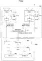
FIG. 1 is a diagram illustrating a configuration of an in-vehicle device control system acting as a moving body device control system, according to an embodiment of the present invention. - The in-vehicle
device control system 1 is installed in areference vehicle 100 such as an automobile that is a moving body. The in-vehicledevice control system 1 includes animaging unit 500, animage analysis unit 600, adisplay monitor 103, and a vehicletraveling control unit 104. The in-vehicledevice control system 1 detects relative height information (information indicating relative inclination condition) of a road surface (moving body traveling surface) ahead of the reference vehicle, from image data each having an image of a forward region of the moving body in a reference vehicle traveling direction (imaging region) obtained by theimaging unit 500, detects a three-dimensional shape of the traveling road surface ahead of the reference vehicle from the detection result of the relative height information, and controls the moving body and various in-vehicle devices using the detection result of the three-dimensional shape of the traveling road surface. The control of the moving body includes, for example, transmission of alert signs, control of a steering wheel of the reference vehicle 100 (reference moving body), or braking of the reference vehicle 100 (the reference moving body). - For example, the
imaging unit 500 is disposed in the vicinity of a rear-view mirror (not illustrated) of awindshield 105 of thereference vehicle 100. Various data such as captured image data obtained by theimaging unit 500 are input into theimage analysis unit 600 acting as an image processing unit. - The
image analysis unit 600 analyzes data transmitted from theimaging unit 500, detects a relative height (positional information) at each point on a road surface ahead of the reference vehicle with respect to a road surface portion (a road surface portion directly beneath the reference vehicle) on which thereference vehicle 100 is traveling, and obtains a three-dimensional shape of the (moving body) traveling road surface ahead of the reference vehicle. Further, theimage analysis unit 600 recognizes recognition target objects such as other vehicles, pedestrians, various obstacles, etc., ahead of the reference vehicle. - The analysis results of the
image analysis unit 600 are sent to thedisplay monitor 103 and the vehicle travelingcontrol unit 104. The display monitor 103 displays captured image data obtained by theimaging unit 500 and analysis results. The vehicle travelingcontrol unit 104 may, for example, send an alert sign to a driver of thereference vehicle 100 or perform traveling support control such as control of the steering wheel and braking of the reference vehicle, based on the recognition results of a recognition target object obtained by theimage analysis unit 600, such as another vehicle, pedestrian, and various obstacles ahead of the vehicle. -
FIG. 2 is a diagram illustrating configurations of theimaging unit 500 and theimage analysis unit 600 according to an embodiment. - The
imaging unit 500 includes a stereo camera having twoimaging parts 510a and 510b as imaging units. The twoimaging parts 510a and 510b are the same components. Theimaging parts 510a and 510b includeimaging lenses sensor substrates image sensors signal processors sensor substrates image sensors imaging unit 500 outputs luminance image data and parallax image data. - In addition, the
imaging unit 500 includes aprocess hardware unit 510 including a Field-Programmable Gate Array (FPGA) or the like. In order to obtain parallax images from the luminance image data output from theimaging parts 510a and 510b, theprocess hardware unit 510 includes adisparity calculation unit 511 as a parallax image information generation unit to calculate a disparity value of a corresponding image portion between the respective captured images captured by theimaging parts 510a and 510b. - The disparity value referred to in this case is a value obtained by taking one of the captured images captured by the
imaging parts 510a and 510b as a reference image, and the other one as a comparison image, and calculating a positional deviation corresponding to a same point within the imaging region of an image portion on the comparison image with respect to an image portion on the reference image, as a disparity value of the image portion. By utilizing the principle of triangulation, a distance to the same point within an imaging region corresponding to the image portion may be calculated based on the disparity value of the image portion. - The
image analysis unit 600 is configured to include an image processing board or the like; theimage analysis unit 600 includes astorage unit 601 having a RAM, a ROM or the like configured to store the luminance image data and the parallax image data output from theimaging unit 500, a central processing unit (CPU) 602 configured to execute a computer program for performing disparity calculation control and the like, a data interface (I/F) 603, and a serial I/F 604. - The FPGA constituting the
process hardware unit 510 executes a process requiring real-time processing on image data, for example, gamma correction, distortion correction (parallelization of left and right captured images), and disparity calculation by block matching to generate parallax images and write the generated information in the RAM of theimage analysis unit 600. The CPU of theimage analysis unit 600 is responsible for control of an image sensor control unit of each of theimaging parts 510a and 510b and overall control of the image processing board. The CPU of theimage analysis unit 600 also loads a program for executing a process of detecting a three-dimensional shape of a road surface, a process of detecting various objects (objects) such as guardrails, and the like from the ROM, executes various kinds of processes by inputting the luminance image data and the parallax image data stored in the RAM, and outputs the process results to the outside from the data I/F 603 and the serial I/F 604. Upon execution of such processes, vehicle operation information, such as vehicle velocity and acceleration (mainly acceleration in a longitudinal direction of the vehicle), steering angle, and yaw rate of thereference vehicle 100, is input via the data I/F 603, and used as parameters of various kinds of processes. The data output to the outside may be used as input data for controlling the various devices of the reference vehicle 100 (brake control, vehicle velocity control, warning control, etc.). - Note that the
imaging unit 500 and theimage analysis unit 600 may integrally form animaging device 2, as an integrated device. -
FIG. 3 is a functional block diagram of an in-vehicledevice control system 1 implemented by theprocess hardware unit 510, theimage analysis unit 600, and the vehicle travelingcontrol unit 104 inFIG. 2 . Note that a functional unit implemented by theimage analysis unit 600 is implemented by a process executed by theCPU 602 of theimage analysis unit 600 by one or more programs installed in theimage analysis unit 600. - The following illustrates processes according to an embodiment.
- A parallax
image generation unit 11 performs a parallax image generation process for generating parallax image data (parallax image information). Note that the parallaximage generation unit 11 is constituted by, for example, a disparity calculation unit 511 (FIG. 2 ). - The parallax image generation process includes, first, setting the luminance image data of one
imaging part 510a of the twoimaging parts 510a and 510b as reference image data, setting the luminance image data of the other imaging part 510b as comparison image data, calculating disparity between the two sets of the luminance image data, generating parallax image data based on the calculated disparity, and outputting the generated parallax image data. The parallax image data indicates a parallax image including respective image portions with respective pixel values according to disparities d calculated for respective image portions on the reference image data. - Specifically, the parallax
image generation unit 11 defines a block including a plurality of pixels (e.g., 16 pixels × 1 pixel) having one target pixel in the center with respect to a certain row of the reference image data. By contrast, in the same row in the comparison image data, a correlation value, which indicates a correlation between a feature quantity indicating a feature of pixel values of a block defined in the reference image data and a feature quantity indicating a feature of pixel values of a corresponding block in the comparison image data, is calculated by shifting a block having the same size as the block of the defined reference image data pixel by pixel in the horizontal line direction (x direction). Then, based on the calculated correlation values, a matching process is performed to select a block of the comparison image data having the highest correlation with the block of the reference image data from among the blocks in the comparison image data. Thereafter, the positional deviation between the target pixel of the block of the reference image data and the corresponding pixel of the block of the comparison image data selected by the matching process is calculated as a disparity value d. The parallax image data may be obtained by performing such a process of calculating a disparity value d on the entire region or a specific region of the reference image data. - As a feature quantity of the block for the matching process, a value (luminance value) of each pixel within a block may be used, for example. As the correlation value, the sum of the absolute values of the difference between the value (luminance value) of each of pixels in the block of the reference image data and the value (luminance value) of a corresponding one of pixels in the block of the comparison image data may be used, for example. In this case, the block having the smallest sum has the highest correlation.
- For the matching process in the parallax
image generation unit 11 to be implemented by the hardware process, methods such as SSD (Sum of Squared Difference), ZSSD (Zero-mean Sum of Squared Difference), SAD (Sum of Absolute Difference), ZSAD (Zero-mean Sum of Absolute Difference), NCC (Normalized cross correlation), and the like may be used. Note that in the matching process, disparity values are calculated only on a pixel basis; hence, when a disparity value of less than one pixel is required, it is necessary to use an estimated value. As an estimation method for a disparity value of less than one pixel, for example, an equiangular linear fitting method, a curve fitting method or the like may be used. - The road
surface estimation unit 12 estimates (detects) a road surface, based on a parallax image generated by the parallaximage generation unit 11. - The functional configuration of the road
surface estimation unit 12 will be described with reference toFIG. 4. FIG. 4 is a functional block diagram of the roadsurface estimation unit 12. - The road
surface estimation unit 12 includes a V-map generation unit 121, a samplepoint extraction unit 122, anoutlier removal unit 123, a road surfaceshape detection unit 124, a roadsurface complement unit 125, asmoothing process unit 126, and a road surface heighttable calculation unit 127. - The following illustrates respective processes of functional units of the road
surface estimation unit 12. - The V-
map generation unit 121 executes a V-map generation process for generating a V-map (a V-Disparity Map, an example of "vertical direction distribution data"), based on parallax pixel data. Each parallax pixel data included in the parallax image data is indicated by a set (x, y, d) of an x direction position, a y direction position, and a disparity value d. The parallax pixel data that is transformed into three-dimensional coordinate information (d, y, f), where d is set on the X axis, y is set on the Y axis, and frequency f is set on the Z axis may be generated as parallax histogram information. Or, three dimensional coordinate information (d, y, f) that is limited to information exceeding a predetermined frequency threshold value from this three-dimensional coordinate information (d, y, f) may be generated as parallax histogram information. The parallax histogram information of the present embodiment includes three-dimensional coordinate information (d, y, f), and this three-dimensional histogram information distributed in the XY two-dimensional coordinate system is referred to as a V-map (V-disparity map). - More specifically, the V-
map generation unit 121 calculates disparity value frequency distribution for each row region of the parallax image data obtained by dividing a parallax image into multiple parts in a vertical direction. The information indicating the disparity value frequency distribution is parallax histogram information. -
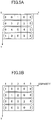
FIGS. 5A and 5B are diagrams illustrating parallax image data and a V-map generated from the parallax image data.FIG. 5A is a diagram illustrating an example of disparity value distribution of a parallax image, andFIG. 5B is a diagram illustrating a V-map indicating the disparity value frequency distribution by each row of the parallax image inFIG. 5A . - When receiving an input of parallax image data having a disparity value distribution as illustrated in
FIG. 5A , the V-map generation unit 121 calculates a disparity value frequency distribution that is a distribution of the number of data sets for each disparity value per row, and outputs the calculated disparity value frequency distribution as parallax histogram information. A V-map as illustrated inFIG. 5B may be obtained by representing information on the disparity value frequency distribution for each row obtained in this manner on a two-dimensional orthogonal coordinate system, where a y-direction position (vertical position of the captured image) on the parallax image is taken on the Y-axis and the disparity value is taken on the X-axis. The V-map may be expressed as an image in which pixels having pixel values according to the frequency f are distributed on the two-dimensional orthogonal coordinate system. -
FIGS. 6A and 6B are diagrams illustrating an example of a captured image as a reference image captured by one imaging part, and an example of a V-map corresponding to the captured image inFIG. 6A , respectively. Note thatFIG. 6A depicts the captured image, andFIG. 6B depicts the V-map. That is, the V-map illustrated inFIG. 6B is generated from the captured image as illustrated inFIG. 6A . In the V-map, no parallax is detected in a region below the road surface, and the parallax is not counted in a shaded region A. - The example of an image in
FIG. 6A depicts aroad surface 401 on which the reference vehicle is traveling, a precedingvehicle 402 existing ahead of the reference vehicle, and autility pole 403 existing off the road. The V-map inFIG. 6B depicts aroad surface 501, a precedingvehicle 502, and autility pole 503 corresponding to the example of the image ofFIG. 6A . - In the example of the image in
FIG. 6A , a relatively flat road surface of the road surface ahead of thereference vehicle 100 matches a virtual reference road surface (virtual reference traveling surface). In other words, a road surface ahead of thereference vehicle 100, which extends parallel to a road surface portion directly beneath thereference vehicle 100 toward a frontward direction of the reference vehicle, matches a virtual reference road surface (virtual reference traveling surface). In this case, in a lower part of the V-map corresponding to a lower part of the image, high frequency points (the road surface 501) are distributed in a substantially linear manner with the inclination such that the disparity value d decreases toward the upper part of the image. Pixels indicating such distribution are present at approximately the same distance in each row on the parallax image, have the highest occupancy rate, and furthermore reflect a detection target having a distance becoming continuously farther toward the upper part of the image. - The
imaging part 510a captures an image in a forward region of the reference vehicle, and content of the captured image indicates, as illustrated inFIG. 6B , that the disparity value d of the road surface decreases toward the upper part of the image inFIG. 6A . Further, the pixels displaying the road surface have substantially the same disparity value d within the same row (horizontal line). Accordingly, the high frequency points (road surface 501) distributed in a substantially linear manner on the V-map correspond to the features of the pixels that display the road surface (vehicle traveling surface). Hence, pixels of points distributed on or near an approximate straight line obtained by linear approximation of high frequency points on the V-map may be estimated as pixels reflecting the road surface with high accuracy. Further, the distance to the road surface portion displayed in each pixel may be obtained with high accuracy from the disparity value d of the corresponding point on the approximate straight line. - The V-
map generation unit 121 may generate a V-map using only pixels in a predetermined region (e.g., a region that may reflect a road surface) in a parallax image, or may generate a V-map using all the pixels in the parallax image. -
FIGS. 7A and 7B are diagrams illustrating an example of a captured image as a reference image captured by one imaging part when noise is generated, and an example of a V-map corresponding to the captured image, respectively. - In the examples of
FIGS. 7A and 7B , a reflected light 404 from a puddle or the like is depicted inFIG. 7A , compared to the examples ofFIG. 6A and FIG. 6B , respectively. Further, a reflected light 504 from a puddle or the like is presented in the V-map depicted inFIG. 7B . As depicted inFIGS. 7A and 7B , when reflected light is generated, erroneous matching or the like occurs for calculating disparity even with parallax on the same road surface. As a result, a disparity value diffing from the original disparity will be calculated. In such a case, the parallax of the road surface is dispersed in the lateral (horizontal) direction as 504 inFIG. 7B . - The sample
point extraction unit 122 extracts sample points used for estimating a road surface from a V-map generated by the V-map generation unit 121. - The following describes examples in which the V-map is divided into a plurality of segments according to a disparity value (i.e., a distance value from the reference vehicle), and the sample point extraction process, the road surface shape detection process, and the like described later are performed. However, the sample point extraction process, the road surface shape detection process, and the like may be performed without dividing the V-map.
- Next, a detailed example of the sample point extraction process performed by the sample
point extraction unit 122 will be described with reference toFIGS. 8 to 11 .FIG. 8 is a flowchart illustrating an example of the sample point extraction process. - First, the sample
point extraction unit 122 divides a V-map into a plurality of segments according to disparity values corresponding to the horizontal axis of the V-map (step S1). - Subsequently, the sample
point extraction unit 122 sets a range (search range) for searching for a sample point to be extracted in a segment (first segment) having the largest disparity value (the closest distance from the reference vehicle) (step S2). -
FIG. 9 is a diagram illustrating an example of a process of extracting sample points from a first segment. - For example, in the first segment, the sample
point extraction unit 122 determines, for example, astart point position 552 of a straight line corresponding to a default road surface 551 ("preset road surface") as a reference point, and sets a predetermined range corresponding to the reference point as a samplepoint search region 553. The data on the default road surface is preset, for example, when a stereo camera is attached to the reference vehicle. For example, data on a flat road surface may be set. - For example, as illustrated in
FIG. 9 , the samplepoint extraction unit 122 may determine asearch region 553 to be an interval between twostraight lines point extraction unit 122 may determine the twostraight lines straight line 554 with respect to inclination of a downhill road surface that may be captured by the stereo camera, and may determine the upperstraight line 555 with respect to the upper limit of inclination of an uphill road surface prescribed by law or the like. Alternatively, the samplepoint extraction unit 122 may set thesearch region 553 to be, for example, a rectangular region. - Subsequently, the sample
point extraction unit 122 extracts a sample point from among pixels included in the search range (step S3). The samplepoint extraction unit 122 may extract one or more sample points from among the pixels included in the search range, for example, for each of coordinate positions of disparity values d. Alternatively, the samplepoint extraction unit 122 may extract the most frequently occurring point indicating the highest frequency (mode) at a coordinate position of each disparity value d as a sample point from among the pixels included in the search range. Or, the samplepoint extraction unit 122 may extract, from among the pixels included in the search range, the most frequently occurring point indicating the highest frequency (mode) at a plurality of coordinate positions including a disparity value d (e.g., the coordinate position of each disparity value d and one or more coordinate positions of at least left or right of the disparity value d) as a sample point. - Subsequently, the
outlier removal unit 123, the road surfaceshape detecting unit 124, and the roadsurface complement unit 125 detect a road surface in the segment including the sample points, based on the sample points extracted in step S3 (step S4). - Subsequently, the sample
point extraction unit 122 determines whether there is a next segment (e.g., a segment having the next smallest disparity value) (step S5), and when there is no next segment (NO in step S5), the sample point extraction unit 131 ends the process. - When there is a next segment (YES in step S5), the sample
point extraction unit 122 acquires an end point position of the road surface detected in step S4 (step S6). - Subsequently, in the next segment, the sample
point extraction unit 122 sets a search range, based on the end point position of the road surface acquired in step S5 (step S7), and proceeds to a process in step S3. -
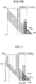
FIGS. 10A and10B are diagrams illustrating an example of a process of extracting sample points from a second segment other than the first segment. For example, in the second segment, the samplepoint extraction unit 122 sets an end point position (a position at which theroad surface 561 of the previous segment contacts the second segment) of theroad surface 561 of the previous segment (a segment adjacent to the second segment and from which the road surface has been already detected) as areference point 562. Then, as is the case of step S2 illustrated inFIG. 9 , the samplepoint extraction unit 122 sets a predetermined range corresponding to thereference point 562 as a samplepoint search region 563. - For example, as illustrated in
FIG. 10A , the samplepoint extraction unit 122 may determine asearch region 563 to be an interval between twostraight lines point extraction unit 122 may determine the twostraight lines point extraction unit 122 may set thesearch region 563 to be a rectangular region having a height corresponding to the y coordinate of thereference point 562, as illustrated inFIG. 10B . -
FIG. 11 is a diagram illustrating another example of a process of extracting sample points from the second segment. - For example, in the second segment, the sample
point extraction unit 122 sets an end point position of a road surface (history road surface) 561a of the segment adjacent to the second segment detected in a frame of the previous parallax image as areference point 562a. Then, the samplepoint extraction unit 122 sets a predetermined range corresponding to thereference point 562a as a samplepoint search region 563a. - As a result, as illustrated in
FIG. 11 , in the case where a difference between the default road surface and the correct (actual)road surface 566 is large, for example, on a road surface of a downward slope, a more appropriate search range may be set compared with the case where the end point position of the road surface is set as the reference point as illustrated inFIGS. 10A and10B . - Note that as the history road surface, the road surface detected in one previous frame may be used, or the average of the road surfaces detected in the plurality of previous frames may be used.
- The
outlier removal unit 123 removes a sample point that is not suitable for linear approximation from among the sample points extracted by the samplepoint extraction unit 122. - The following illustrates an outlier removal process performed by the
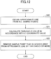
outlier removal unit 123 with reference toFIGS. 12 and13 .FIG. 12 is a flowchart illustrating an example of an outlier removal process.FIG. 13 is a diagram illustrating a process of removing an outlier. - First, the
outlier removal unit 123 calculates an approximate straight line from the sample points of each segment extracted by the samplepoint extraction unit 122 or from the sample points of all segments (step S20). Theoutlier removal unit 123 calculates an approximate straight line using, for example, a least squares method. In the example ofFIG. 13 , the approximatestraight line 541 is calculated in step S20 inFIG. 12 . - Subsequently, the
outlier removal unit 123 calculates a threshold value according to a value of an X coordinate (step S21). In the example ofFIG. 13 , with a predetermined X coordinate value D (e.g., a disparity value corresponding to a distance of 50 m from the reference vehicle) as a boundary, a predetermined value 2o is set to X coordinate values less than the predetermined X coordinate value D (a predetermined distance farther from the reference vehicle), and a predetermined value σ is set to X coordinate values having the predetermined X coordinate value D or more (a predetermined distance or less from the reference vehicle). This is because the threshold for removing an outlier needs to be relaxed because an error generated when measuring with a stereo camera is large for the road surface where the disparity values are small, that is, for the distance from the reference vehicle being long. - Subsequently, the
outlier removal unit 123 removes a sample point having the Euclidean distance being equal to or greater than the threshold value calculated in step S21 with respect to the calculated approximate straight line (step S22). In the example ofFIG. 13 , thesample point 542 having an X coordinate value equal to or greater than D and being separated by a predetermined threshold σ or more is removed. For example, for a value greater than or equal to D, σ may be set in two or more places, and σ may be calculated and set as a function of disparity d. - The road surface
shape detection unit 124 detects a shape (position, height) of the road surface from each segment of the V-map generated by the V-map generation unit 121, based on the sample points extracted by the samplingpoint extraction unit 122 and not removed by theoutlier removal unit 123. - The road surface
shape detection unit 124 calculates an approximate straight line from the sample points of each segment, for example, by a least squares method, and detects (estimates) the calculated approximate straight line as a road surface. - The road
surface complement unit 125 determines whether the road surface detected (estimated) by the road surfaceshape detection unit 124 is inappropriate. When the roadsurface complement unit 125 determines that the detected road surface is inappropriate, the roadsurface complement unit 125 complements the road surface. The determination as to whether the detected road surface is inappropriate may be made based on not only the determination on the angle of the road surface but also a case where the score used for the estimation is smaller than a predetermined threshold value or a case where the correlation coefficient when approximating by the least squares method is smaller than a predetermined value (when the point group variability is large). - The road
surface complement unit 125 determines whether an inappropriate road surface that is impossible to be captured by a stereo camera has been estimated due to noise. When the roadsurface complement unit 125 determines that an inappropriate road surface has been estimated, the roadsurface complement unit 125 complements (interpolates) the inappropriate road surface, based on a default road surface or road surface data estimated in the previous frames. - In the V-map, for example, when data of a steeply left-side upward-sloping road surface having part of the gradient being a predetermined value or more is detected, the road surface road
surface complement unit 125 assumes that the road surface is a downhill slope with a steep gradient as the distance from the reference vehicle increases. Then, the roadsurface complement unit 125 removes the data of the road surface and complements the removed road surface data with data such as a default road surface instead. - The
smoothing process unit 126 corrects a road surface estimated in each segment such that the estimated road surfaces are continuous. Thesmoothing process unit 126 changes inclination and intercept of each of the road surfaces such that an end point (endpoint) of one of the road surfaces estimated in the two adjacent segments matches a start point (endpoint) of the other road surface. - The road surface height
table calculation unit 127 performs a road surface height table calculation process of calculating a road surface height (a relative height with respect to the road surface portion directly beneath the reference vehicle), based on the road surface in each segment corrected by thesmoothing process unit 126, and converting calculated results into a table. - The road surface height
table calculation unit 127 calculates a distance to each road surface portion displayed in each row region (each position in the vertical direction of an image) on the captured image from information on the road surface in each segment. It is predetermined which row region in the captured image is to display each road surface portion in a vehicle traveling direction of a virtual plane, which is obtained by extending a road surface portion located directly beneath the reference vehicle in a forward traveling direction of the reference vehicle in parallel with the road surface portion. This virtual plane (reference road surface) is represented by a straight line (reference straight line) on the V-map. The road surface heighttable calculation unit 127 may obtain the height of each road surface portion ahead of the reference vehicle by comparing the road surface in each segment with the reference straight line. The road surface heighttable calculation unit 127 may simply calculate the height of the road surface portion existing ahead of the reference vehicle by the distance from the Y axis position on the road surface in each segment obtained from the corresponding disparity value. The road surface heighttable calculation unit 127 tabulates the height of each road surface portion obtained from the approximate straight line with respect to the necessary disparity range. - Note that the height of an object displayed on the captured image portion corresponding to a certain point where the Y axis position is y' at a disparity value d from the road surface may be calculated from (y'-y0) when the Y-axis position on the road surface at the disparity value d is y0. In general, the height H of the object corresponding to the coordinates (d, y') on the V-map from the road surface may be calculated from the following formula. Note that "Z" in the following formula is a distance (Z = BF/(d-offset)) calculated from the disparity value d, and "f" is a value obtained by converting a focal distance of a camera into the same unit as that of (y'-Y0). Note that "BF" is a value obtained by multiplying the baseline length of a stereo camera by the focal length, and "offset" is a disparity value when an object at infinity is imaged.

- A
clustering unit 13 generates XY two-dimensional histogram information (frequency U-map) by setting a set (x, y, d) of x being an x direction position, y being a y direction position, and d being a parallax value d in each parallax pixel data included in the parallax image data, such that x is set on the X axis, d is set on the Y axis, and the frequency is set on the Z axis. - The
clustering unit 13 generates a frequency U-map only for the points (x, y, d) of the parallax image in which the height H from the road surface is within a predetermined height range (e.g., 20 cm to 3 m), based on the height of each road surface portion tabulated by the road surface heighttable calculation unit 127. In this case, it is possible to appropriately extract an object existing in the predetermined height range from the road surface. - In the frequency U-map, the
clustering unit 13 detects, as an object region, a region where the frequency is greater than a predetermined value and the parallax is dense, and assigns, to the object region, individual information, such as coordinates on the parallax image and a type (human or pedestrian) of an object predicted from the actual size (size) of the object. - The
rejection unit 14 rejects information on an object that is not a recognition target based on the parallax image, the frequency U-map, and the individual information of the object. - A
tracking unit 15 determines whether the detected object is a tracking target when the detected object appears consecutively in frames of a plurality of parallax images. - A control unit 139 may, for example, send an alert sign to a driver of the
reference vehicle 100 or perform traveling support control (driving support control) such as control of the steering wheel and braking of the reference vehicle, based on the detection result of the object by theclustering unit 13. - When noise is generated in parallax due to reflection of the road surface during rainy weather, an estimated road surface may be too low or too high with respect to the correct road surface. When the estimated road surface is too low, a part of the road surface may be erroneously recognized as an obstacle. When the estimated road surface is too high, an obstacle or the like lower than the estimated road surface will not be detected in some cases.
- According to the above-described embodiment, in the V-map, a search range corresponding to a predetermined reference point is set, a plurality of pixels are extracted from the search range, and a road surface is detected based on the extracted plurality of pixels. This makes it possible to improve the accuracy of detecting a road surface.
- Note that since a value of a distance (distance value) and a disparity value may be handled equivalently, a parallax image is used as an example of a range image in the present embodiments; however, the present invention is not limited to this example. For example, a range image may be generated by integrating distance information generated by using a detection device such as millimeter wave radar or laser radar with respect to a parallax image generated by using a stereo camera. Further, a combination of a stereo camera and a detection device such as millimeter wave radar or laser radar may combine a detection result of an object obtained by the detection device with the detection result of the object obtained by the above-described stereo camera to further improve detection accuracy.
- The system configuration in the above-described embodiments is merely an example, and various examples of the system configuration may also be applied according to intended use and purposes.
- For example, because the processes of the
outlier removal unit 123, the roadsurface complement unit 125, thesmoothing process unit 126 and the like are not indispensable, the system configuration may exclude these functional units. - In addition, respective functional units of the
process hardware unit 510, theimage analysis unit 600, and the vehicle travelingcontrol unit 104 may be implemented by hardware, or may be implemented by a CPU executing a program stored in a storage device. The above-described program may be distributed in a form of a computer-readable recording medium storing the program in files of an installable format or executable format. Or other examples of the recording medium may include a compact disc recordable (CD-R), a digital versatile disk (DVD), and a Blu-ray Disc. The above-described recording media that store the above-described programs such as a CD-ROM, and an HD 504 that store these programs may be provided domestically or internationally as a program product. - Although the present invention has been described based on the embodiments, the present invention is not limited to the above-described embodiments, and various modifications may be made within the scope described in the claims.
- The present application is based on and claims the benefit of priority of Japanese Priority Application No.
2016-047574, filed on March 10, 2016 -
- 1 in-vehicle device control system (example of moving body device control system)
- 100 reference vehicle
- 101 imaging unit
- 103 display monitor
- 106 vehicle traveling control unit (an example of "control unit")
- 11 parallax image generation unit (an example of "distance image generation unit")
- 12 road surface estimation unit (an example of "estimation unit")
- 121 V-map generation unit (an example of "generation unit")
- 122 sample point extraction unit
- 123 outlier removal unit
- 124 road surface shape detection unit
- 125 road surface complement unit
- 126 smoothing process unit
- 127 road surface height table calculation unit
- 13 clustering unit (an example of "object detection unit")
- 14 rejection unit
- 15 tracking unit
- 16 control unit
- 2 imaging device
- 510a,510b imaging part
- 510 process hardware unit
- 600 image analysis unit (an example of "image processing apparatus")
Claims (8)
- An image processing apparatus comprising:a generation unit configured to generate vertical direction distribution data indicating a frequency distribution of distance values with respect to a vertical direction of a range image, from the range image having distance values according to distance of a road surface in a plurality of captured images captured by a plurality of imaging parts;an extraction unit configured to set a search range corresponding to a predetermined reference point in the vertical direction distribution data and extract a plurality of pixels from the search range; anda detection unit configured to detect a road surface, based on the plurality of extracted pixels.
- The image processing apparatus according to claim 1, wherein
the extraction unit sets the search range corresponding to an angle at which a road surface is allowed to be inclined from the predetermined reference point. - The image processing apparatus according to claim 1 or 2, wherein
the extraction unit determines the predetermined reference point according to the road surface detected by the detection unit or a preset road surface based on the plurality of captured images captured previously. - The image processing apparatus according to any one of claims 1 to 3, wherein
the extraction unit divides the vertical direction distribution data into a first segment and a second segment according to a distance value, and determines the predetermined reference point in the second segment according to a road surface detected in the first segment. - An imaging device comprising:a plurality of imaging parts configured to capture an image;a range image generation unit configured to generate a range image having distance values according to parallax of a road surface in a plurality of captured images, from the plurality of captured images captured by the plurality of imaging parts;a distribution data generation unit configured to generate vertical direction distribution data indicating a frequency distribution of distance values with respect to a vertical direction of the range image;an extraction unit configured to set a search range corresponding to a predetermined reference point in the vertical direction distribution data and extract a plurality of pixels from the search range; anda detection unit configured to detect the road surface, based on the plurality of extracted pixels.
- A moving body device control system comprising:a plurality of imaging parts installed in a moving body and configured to image a view ahead of the moving body;a range image generation unit configured to generate a range image having distance values according to parallax of a road surface in a plurality of captured images, from the plurality of captured images captured by the plurality of imaging parts;a distribution data generation unit configured to generate vertical direction distribution data indicating a frequency distribution of distance values with respect to a vertical direction of the range image;an extraction unit configured to set a search range corresponding to a predetermined reference point in the vertical direction distribution data, and extract a plurality of pixels from the search range; anda road surface detection unit configured to detect a road surface, based on the plurality of extracted pixels;an object detection unit configured to detect an object in the plurality of captured images, based on the detected road surface detected by the road surface detection unit and the range image; anda control unit configured to control the moving body, based on data on the detected object detected by the object detection unit.
- An image processing method performed by a computer, the image processing method comprising:generating vertical direction distribution data indicating a frequency distribution of distance values with respect to a vertical direction of a range image, from the range image having distance values according to distance of a road surface in a plurality of captured images captured by a plurality of imaging parts;setting a search range corresponding to a predetermined reference point in the vertical direction distribution data and extracting a plurality of pixels from the search range; anddetecting the road surface, based on the plurality of extracted pixels.
- A program, which when processed by one or more processors causes a computer to execute a process comprising:generating vertical direction distribution data indicating a frequency distribution of distance values with respect to a vertical direction of a range image, from the range image having distance values according to distance of a road surface in a plurality of captured images captured by a plurality of imaging parts;setting a search range corresponding to a predetermined reference point in the vertical direction distribution data and extracting a plurality of pixels from the search range; anddetecting the road surface, based on the plurality of extracted pixels.
Applications Claiming Priority (2)
| Application Number | Priority Date | Filing Date | Title |
|---|---|---|---|
| JP2016047574 | 2016-03-10 | ||
| PCT/JP2017/002393 WO2017154389A1 (en) | 2016-03-10 | 2017-01-24 | Image processing device, imaging device, mobile apparatus control system, image processing method, and program |
Publications (2)
| Publication Number | Publication Date |
|---|---|
| EP3428902A1 true EP3428902A1 (en) | 2019-01-16 |
| EP3428902A4 EP3428902A4 (en) | 2019-08-14 |
Family
ID=59790244
Family Applications (1)
| Application Number | Title | Priority Date | Filing Date |
|---|---|---|---|
| EP17762735.3A Withdrawn EP3428902A4 (en) | 2016-03-10 | 2017-01-24 | IMAGE PROCESSING DEVICE, IMAGING DEVICE, MOBILE DEVICE CONTROL SYSTEM, IMAGE PROCESSING METHOD, AND PROGRAM |
Country Status (4)
| Country | Link |
|---|---|
| US (1) | US11691585B2 (en) |
| EP (1) | EP3428902A4 (en) |
| JP (1) | JP6769477B2 (en) |
| WO (1) | WO2017154389A1 (en) |
Cited By (1)
| Publication number | Priority date | Publication date | Assignee | Title |
|---|---|---|---|---|
| EP3709265A4 (en) * | 2017-11-08 | 2021-08-04 | Clarion Co., Ltd. | Road surface area detection device |
Families Citing this family (7)
| Publication number | Priority date | Publication date | Assignee | Title |
|---|---|---|---|---|
| JP6743882B2 (en) * | 2016-03-14 | 2020-08-19 | 株式会社リコー | Image processing device, device control system, imaging device, image processing method, and program |
| JP6406289B2 (en) * | 2016-03-14 | 2018-10-17 | オムロン株式会社 | Road surface shape measuring apparatus, measuring method, and program |
| JP6660367B2 (en) | 2017-12-25 | 2020-03-11 | 株式会社Subaru | Outside environment recognition device |
| CN109191512B (en) * | 2018-07-27 | 2020-10-30 | 深圳市商汤科技有限公司 | Binocular image depth estimation method, binocular image depth estimation device, binocular image depth estimation apparatus, program, and medium |
| CN109144097B (en) * | 2018-08-15 | 2021-04-06 | 广州极飞科技有限公司 | Obstacle or ground recognition and flight control method, device, equipment and medium |
| JP7262350B2 (en) * | 2019-09-12 | 2023-04-21 | 京セラ株式会社 | Road surface detection device, object detection device, object detection system, moving body and object detection method |
| JP7522616B2 (en) * | 2020-08-31 | 2024-07-25 | 株式会社Subaru | Outside environment recognition device |
Family Cites Families (19)
| Publication number | Priority date | Publication date | Assignee | Title |
|---|---|---|---|---|
| JP4719543B2 (en) | 2005-09-26 | 2011-07-06 | 株式会社リコー | Workflow system, server device, processing method of workflow system, and workflow program |
| JP2007102545A (en) | 2005-10-05 | 2007-04-19 | Ricoh Co Ltd | Electronic document creation apparatus, electronic document creation method, and electronic document creation program |
| JP4647515B2 (en) | 2006-02-20 | 2011-03-09 | 株式会社リコー | Coordinate detection device, writing instrument, and coordinate input system |
| US7873215B2 (en) * | 2007-06-27 | 2011-01-18 | Seiko Epson Corporation | Precise identification of text pixels from scanned document images |
| CN103177236B (en) * | 2011-12-22 | 2016-06-01 | 株式会社理光 | Road area detection method and device, lane line detection method and apparatus |
| CN103854008B (en) * | 2012-12-04 | 2019-10-18 | 株式会社理光 | Road surface detection method and device |
| JP6274557B2 (en) * | 2013-02-18 | 2018-02-07 | 株式会社リコー | Moving surface information detection apparatus, moving body device control system using the same, and moving surface information detection program |
| JP6398347B2 (en) | 2013-08-15 | 2018-10-03 | 株式会社リコー | Image processing apparatus, recognition object detection method, recognition object detection program, and moving object control system |
| JP6151150B2 (en) * | 2013-10-07 | 2017-06-21 | 日立オートモティブシステムズ株式会社 | Object detection device and vehicle using the same |
| JP5874756B2 (en) * | 2014-02-07 | 2016-03-02 | トヨタ自動車株式会社 | Marking line detection system and marking line detection method |
| JP6459659B2 (en) | 2014-03-18 | 2019-01-30 | 株式会社リコー | Image processing apparatus, image processing method, driving support system, program |
| JP6519262B2 (en) * | 2014-04-10 | 2019-05-29 | 株式会社リコー | Three-dimensional object detection device, three-dimensional object detection method, three-dimensional object detection program, and mobile device control system |
| JP6550881B2 (en) * | 2014-07-14 | 2019-07-31 | 株式会社リコー | Three-dimensional object detection device, three-dimensional object detection method, three-dimensional object detection program, and mobile device control system |
| US20160019429A1 (en) | 2014-07-17 | 2016-01-21 | Tomoko Ishigaki | Image processing apparatus, solid object detection method, solid object detection program, and moving object control system |
| JP6440411B2 (en) * | 2014-08-26 | 2018-12-19 | 日立オートモティブシステムズ株式会社 | Object detection device |
| JP6805534B2 (en) * | 2015-07-02 | 2020-12-23 | 株式会社リコー | Parallax image generator, parallax image generation method and parallax image generation program, object recognition device, device control system |
| JP6662388B2 (en) | 2015-11-27 | 2020-03-11 | 株式会社リコー | Image processing device, imaging device, device control system, distribution data generation method, and program |
| WO2017094300A1 (en) * | 2015-11-30 | 2017-06-08 | 株式会社リコー | Image processing device, object recognition device, device conrol system, image processing method, and program |
| EP3176013B1 (en) * | 2015-12-01 | 2019-07-17 | Honda Research Institute Europe GmbH | Predictive suspension control for a vehicle using a stereo camera sensor |
-
2017
- 2017-01-24 WO PCT/JP2017/002393 patent/WO2017154389A1/en not_active Ceased
- 2017-01-24 JP JP2018504047A patent/JP6769477B2/en active Active
- 2017-01-24 EP EP17762735.3A patent/EP3428902A4/en not_active Withdrawn
-
2018
- 2018-09-05 US US16/122,445 patent/US11691585B2/en active Active
Cited By (2)
| Publication number | Priority date | Publication date | Assignee | Title |
|---|---|---|---|---|
| EP3709265A4 (en) * | 2017-11-08 | 2021-08-04 | Clarion Co., Ltd. | Road surface area detection device |
| US11403770B2 (en) | 2017-11-08 | 2022-08-02 | Clarion Co., Ltd. | Road surface area detection device |
Also Published As
| Publication number | Publication date |
|---|---|
| US11691585B2 (en) | 2023-07-04 |
| JPWO2017154389A1 (en) | 2019-02-28 |
| JP6769477B2 (en) | 2020-10-14 |
| EP3428902A4 (en) | 2019-08-14 |
| WO2017154389A1 (en) | 2017-09-14 |
| US20190001910A1 (en) | 2019-01-03 |
Similar Documents
| Publication | Publication Date | Title |
|---|---|---|
| US10885351B2 (en) | Image processing apparatus to estimate a plurality of road surfaces | |
| US10580155B2 (en) | Image processing apparatus, imaging device, device control system, frequency distribution image generation method, and recording medium | |
| US11691585B2 (en) | Image processing apparatus, imaging device, moving body device control system, image processing method, and program product | |
| US10984509B2 (en) | Image processing apparatus, imaging device, moving body device control system, image information processing method, and program product | |
| US10755116B2 (en) | Image processing apparatus, imaging apparatus, and device control system | |
| US11004215B2 (en) | Image processing apparatus, imaging device, moving body device control system, image information processing method, and program product | |
| JP6733225B2 (en) | Image processing device, imaging device, mobile device control system, image processing method, and program | |
| JP6705496B2 (en) | Image processing device, imaging device, mobile device control system, mobile device, image processing method, and program | |
| JP7206583B2 (en) | Information processing device, imaging device, device control system, moving object, information processing method and program | |
| EP3282389B1 (en) | Image processing apparatus, image capturing apparatus, moving body apparatus control system, image processing method, and program | |
| JP6583527B2 (en) | Image processing apparatus, imaging apparatus, mobile device control system, image processing method, and program | |
| US10628960B2 (en) | Information processing apparatus, imaging apparatus, device control system, moving object, information processing method, and recording medium | |
| WO2017145634A1 (en) | Image processing device, imaging device, system for controlling mobile body, image processing method, and program | |
| JP6711128B2 (en) | Image processing device, imaging device, mobile device control system, image processing method, and program | |
| JP2017207874A (en) | Image processing apparatus, imaging apparatus, moving body device control system, image processing method, and program | |
| EP3287948B1 (en) | Image processing apparatus, moving body apparatus control system, image processing method, and program | |
| JP6763198B2 (en) | Image processing equipment, imaging equipment, mobile device control systems, image processing methods, and programs | |
| JP2018088234A (en) | Information processing apparatus, imaging apparatus, device control system, moving object, information processing method, and program | |
| EP3327696B1 (en) | Information processing apparatus, imaging device, device control system, mobile body, information processing method, and program |
Legal Events
| Date | Code | Title | Description |
|---|---|---|---|
| STAA | Information on the status of an ep patent application or granted ep patent |
Free format text: STATUS: THE INTERNATIONAL PUBLICATION HAS BEEN MADE |
|
| PUAI | Public reference made under article 153(3) epc to a published international application that has entered the european phase |
Free format text: ORIGINAL CODE: 0009012 |
|
| STAA | Information on the status of an ep patent application or granted ep patent |
Free format text: STATUS: REQUEST FOR EXAMINATION WAS MADE |
|
| 17P | Request for examination filed |
Effective date: 20180905 |
|
| AK | Designated contracting states |
Kind code of ref document: A1 Designated state(s): AL AT BE BG CH CY CZ DE DK EE ES FI FR GB GR HR HU IE IS IT LI LT LU LV MC MK MT NL NO PL PT RO RS SE SI SK SM TR |
|
| AX | Request for extension of the european patent |
Extension state: BA ME |
|
| DAV | Request for validation of the european patent (deleted) | ||
| DAX | Request for extension of the european patent (deleted) | ||
| A4 | Supplementary search report drawn up and despatched |
Effective date: 20190712 |
|
| RIC1 | Information provided on ipc code assigned before grant |
Ipc: B60R 21/01 20060101ALN20190708BHEP Ipc: G06T 1/60 20060101ALN20190708BHEP Ipc: B60R 21/00 20060101ALI20190708BHEP Ipc: G08G 1/16 20060101AFI20190708BHEP Ipc: B60R 21/02 20060101ALN20190708BHEP Ipc: G06K 9/00 20060101ALI20190708BHEP Ipc: G06T 7/00 20170101ALI20190708BHEP |
|
| STAA | Information on the status of an ep patent application or granted ep patent |
Free format text: STATUS: EXAMINATION IS IN PROGRESS |
|
| 17Q | First examination report despatched |
Effective date: 20210301 |
|
| REG | Reference to a national code |
Ref country code: DE Ref legal event code: R079 Free format text: PREVIOUS MAIN CLASS: G08G0001160000 Ipc: G06V0020560000 |
|
| RIC1 | Information provided on ipc code assigned before grant |
Ipc: G06T 1/60 20060101ALN20241031BHEP Ipc: B60R 21/02 20060101ALN20241031BHEP Ipc: B60R 21/01 20060101ALN20241031BHEP Ipc: B60R 21/00 20060101ALI20241031BHEP Ipc: G08G 1/16 20060101ALI20241031BHEP Ipc: G06T 7/00 20170101ALI20241031BHEP Ipc: G06V 20/56 20220101AFI20241031BHEP |
|
| RIC1 | Information provided on ipc code assigned before grant |
Ipc: G06T 1/60 20060101ALN20241211BHEP Ipc: B60R 21/02 20060101ALN20241211BHEP Ipc: B60R 21/01 20060101ALN20241211BHEP Ipc: B60R 21/00 20060101ALI20241211BHEP Ipc: G08G 1/16 20060101ALI20241211BHEP Ipc: G06T 7/00 20170101ALI20241211BHEP Ipc: G06V 20/56 20220101AFI20241211BHEP |
|
| RIC1 | Information provided on ipc code assigned before grant |
Ipc: G06T 1/60 20060101ALN20250113BHEP Ipc: B60R 21/02 20060101ALN20250113BHEP Ipc: B60R 21/01 20060101ALN20250113BHEP Ipc: B60R 21/00 20060101ALI20250113BHEP Ipc: G08G 1/16 20060101ALI20250113BHEP Ipc: G06T 7/00 20170101ALI20250113BHEP Ipc: G06V 20/56 20220101AFI20250113BHEP |
|
| STAA | Information on the status of an ep patent application or granted ep patent |
Free format text: STATUS: THE APPLICATION IS DEEMED TO BE WITHDRAWN |
|
| 18D | Application deemed to be withdrawn |
Effective date: 20250801 |