EP3428896B1 - Systems and methods for delaying or activating a blowout device or a purge device in a sampling pipe network of an aspirated smoke detection system - Google Patents
Systems and methods for delaying or activating a blowout device or a purge device in a sampling pipe network of an aspirated smoke detection system Download PDFInfo
- Publication number
- EP3428896B1 EP3428896B1 EP18176790.6A EP18176790A EP3428896B1 EP 3428896 B1 EP3428896 B1 EP 3428896B1 EP 18176790 A EP18176790 A EP 18176790A EP 3428896 B1 EP3428896 B1 EP 3428896B1
- Authority
- EP
- European Patent Office
- Prior art keywords
- blowout
- sampling pipe
- delay
- action
- smoke detector
- Prior art date
- Legal status (The legal status is an assumption and is not a legal conclusion. Google has not performed a legal analysis and makes no representation as to the accuracy of the status listed.)
- Active
Links
Images


Classifications
-
- G—PHYSICS
- G08—SIGNALLING
- G08B—SIGNALLING SYSTEMS, e.g. PERSONAL CALLING SYSTEMS; ORDER TELEGRAPHS; ALARM SYSTEMS
- G08B29/00—Checking or monitoring of signalling or alarm systems; Prevention or correction of operating errors, e.g. preventing unauthorised operation
- G08B29/18—Prevention or correction of operating errors
-
- B—PERFORMING OPERATIONS; TRANSPORTING
- B08—CLEANING
- B08B—CLEANING IN GENERAL; PREVENTION OF FOULING IN GENERAL
- B08B9/00—Cleaning hollow articles by methods or apparatus specially adapted thereto
- B08B9/02—Cleaning pipes or tubes or systems of pipes or tubes
- B08B9/027—Cleaning the internal surfaces; Removal of blockages
- B08B9/032—Cleaning the internal surfaces; Removal of blockages by the mechanical action of a moving fluid, e.g. by flushing
- B08B9/0321—Cleaning the internal surfaces; Removal of blockages by the mechanical action of a moving fluid, e.g. by flushing using pressurised, pulsating or purging fluid
- B08B9/0323—Arrangements specially designed for simultaneous and parallel cleaning of a plurality of conduits
-
- B—PERFORMING OPERATIONS; TRANSPORTING
- B08—CLEANING
- B08B—CLEANING IN GENERAL; PREVENTION OF FOULING IN GENERAL
- B08B9/00—Cleaning hollow articles by methods or apparatus specially adapted thereto
- B08B9/02—Cleaning pipes or tubes or systems of pipes or tubes
- B08B9/027—Cleaning the internal surfaces; Removal of blockages
- B08B9/032—Cleaning the internal surfaces; Removal of blockages by the mechanical action of a moving fluid, e.g. by flushing
- B08B9/0321—Cleaning the internal surfaces; Removal of blockages by the mechanical action of a moving fluid, e.g. by flushing using pressurised, pulsating or purging fluid
- B08B9/0325—Control mechanisms therefor
-
- B—PERFORMING OPERATIONS; TRANSPORTING
- B08—CLEANING
- B08B—CLEANING IN GENERAL; PREVENTION OF FOULING IN GENERAL
- B08B9/00—Cleaning hollow articles by methods or apparatus specially adapted thereto
- B08B9/02—Cleaning pipes or tubes or systems of pipes or tubes
- B08B9/027—Cleaning the internal surfaces; Removal of blockages
- B08B9/032—Cleaning the internal surfaces; Removal of blockages by the mechanical action of a moving fluid, e.g. by flushing
- B08B9/0321—Cleaning the internal surfaces; Removal of blockages by the mechanical action of a moving fluid, e.g. by flushing using pressurised, pulsating or purging fluid
- B08B9/0328—Cleaning the internal surfaces; Removal of blockages by the mechanical action of a moving fluid, e.g. by flushing using pressurised, pulsating or purging fluid by purging the pipe with a gas or a mixture of gas and liquid
-
- G—PHYSICS
- G08—SIGNALLING
- G08B—SIGNALLING SYSTEMS, e.g. PERSONAL CALLING SYSTEMS; ORDER TELEGRAPHS; ALARM SYSTEMS
- G08B17/00—Fire alarms; Alarms responsive to explosion
- G08B17/10—Actuation by presence of smoke or gases, e.g. automatic alarm devices for analysing flowing fluid materials by the use of optical means
-
- G—PHYSICS
- G08—SIGNALLING
- G08B—SIGNALLING SYSTEMS, e.g. PERSONAL CALLING SYSTEMS; ORDER TELEGRAPHS; ALARM SYSTEMS
- G08B17/00—Fire alarms; Alarms responsive to explosion
- G08B17/10—Actuation by presence of smoke or gases, e.g. automatic alarm devices for analysing flowing fluid materials by the use of optical means
- G08B17/103—Actuation by presence of smoke or gases, e.g. automatic alarm devices for analysing flowing fluid materials by the use of optical means using a light emitting and receiving device
-
- G—PHYSICS
- G08—SIGNALLING
- G08B—SIGNALLING SYSTEMS, e.g. PERSONAL CALLING SYSTEMS; ORDER TELEGRAPHS; ALARM SYSTEMS
- G08B17/00—Fire alarms; Alarms responsive to explosion
- G08B17/10—Actuation by presence of smoke or gases, e.g. automatic alarm devices for analysing flowing fluid materials by the use of optical means
- G08B17/103—Actuation by presence of smoke or gases, e.g. automatic alarm devices for analysing flowing fluid materials by the use of optical means using a light emitting and receiving device
- G08B17/107—Actuation by presence of smoke or gases, e.g. automatic alarm devices for analysing flowing fluid materials by the use of optical means using a light emitting and receiving device for detecting light-scattering due to smoke
-
- G—PHYSICS
- G08—SIGNALLING
- G08B—SIGNALLING SYSTEMS, e.g. PERSONAL CALLING SYSTEMS; ORDER TELEGRAPHS; ALARM SYSTEMS
- G08B17/00—Fire alarms; Alarms responsive to explosion
- G08B17/10—Actuation by presence of smoke or gases, e.g. automatic alarm devices for analysing flowing fluid materials by the use of optical means
- G08B17/11—Actuation by presence of smoke or gases, e.g. automatic alarm devices for analysing flowing fluid materials by the use of optical means using an ionisation chamber for detecting smoke or gas
- G08B17/113—Constructional details
-
- G—PHYSICS
- G08—SIGNALLING
- G08B—SIGNALLING SYSTEMS, e.g. PERSONAL CALLING SYSTEMS; ORDER TELEGRAPHS; ALARM SYSTEMS
- G08B17/00—Fire alarms; Alarms responsive to explosion
- G08B17/10—Actuation by presence of smoke or gases, e.g. automatic alarm devices for analysing flowing fluid materials by the use of optical means
- G08B17/117—Actuation by presence of smoke or gases, e.g. automatic alarm devices for analysing flowing fluid materials by the use of optical means by using a detection device for specific gases, e.g. combustion products, produced by the fire
-
- G—PHYSICS
- G08—SIGNALLING
- G08B—SIGNALLING SYSTEMS, e.g. PERSONAL CALLING SYSTEMS; ORDER TELEGRAPHS; ALARM SYSTEMS
- G08B21/00—Alarms responsive to a single specified undesired or abnormal condition and not otherwise provided for
- G08B21/18—Status alarms
- G08B21/182—Level alarms, e.g. alarms responsive to variables exceeding a threshold
-
- G—PHYSICS
- G08—SIGNALLING
- G08B—SIGNALLING SYSTEMS, e.g. PERSONAL CALLING SYSTEMS; ORDER TELEGRAPHS; ALARM SYSTEMS
- G08B25/00—Alarm systems in which the location of the alarm condition is signalled to a central station, e.g. fire or police telegraphic systems
- G08B25/002—Generating a prealarm to the central station
-
- G—PHYSICS
- G08—SIGNALLING
- G08B—SIGNALLING SYSTEMS, e.g. PERSONAL CALLING SYSTEMS; ORDER TELEGRAPHS; ALARM SYSTEMS
- G08B29/00—Checking or monitoring of signalling or alarm systems; Prevention or correction of operating errors, e.g. preventing unauthorised operation
- G08B29/02—Monitoring continuously signalling or alarm systems
- G08B29/04—Monitoring of the detection circuits
- G08B29/043—Monitoring of the detection circuits of fire detection circuits
-
- G—PHYSICS
- G08—SIGNALLING
- G08B—SIGNALLING SYSTEMS, e.g. PERSONAL CALLING SYSTEMS; ORDER TELEGRAPHS; ALARM SYSTEMS
- G08B29/00—Checking or monitoring of signalling or alarm systems; Prevention or correction of operating errors, e.g. preventing unauthorised operation
- G08B29/12—Checking intermittently signalling or alarm systems
- G08B29/14—Checking intermittently signalling or alarm systems checking the detection circuits
- G08B29/145—Checking intermittently signalling or alarm systems checking the detection circuits of fire detection circuits
-
- G—PHYSICS
- G08—SIGNALLING
- G08B—SIGNALLING SYSTEMS, e.g. PERSONAL CALLING SYSTEMS; ORDER TELEGRAPHS; ALARM SYSTEMS
- G08B29/00—Checking or monitoring of signalling or alarm systems; Prevention or correction of operating errors, e.g. preventing unauthorised operation
- G08B29/18—Prevention or correction of operating errors
- G08B29/20—Calibration, including self-calibrating arrangements
- G08B29/24—Self-calibration, e.g. compensating for environmental drift or ageing of components
-
- B—PERFORMING OPERATIONS; TRANSPORTING
- B08—CLEANING
- B08B—CLEANING IN GENERAL; PREVENTION OF FOULING IN GENERAL
- B08B2209/00—Details of machines or methods for cleaning hollow articles
- B08B2209/02—Details of apparatuses or methods for cleaning pipes or tubes
- B08B2209/027—Details of apparatuses or methods for cleaning pipes or tubes for cleaning the internal surfaces
- B08B2209/032—Details of apparatuses or methods for cleaning pipes or tubes for cleaning the internal surfaces by the mechanical action of a moving fluid
Definitions
- the present invention relates generally to a smoke detection system. More particularly, the present invention relates to systems and methods for delaying or activating a blowout device or a purge device in a sampling pipe network of an aspirated smoke detection system.
- a sampling pipe network of an aspirated smoke detection system will experience accumulated particulate and contaminants, such as dust, in sampling holes of pipes in the network and inside of the pipes themselves. Such accumulated particulate and contaminants can restrict the flow of air within the pipes and eventually cause a low flow fault event in the aspirated smoke detection system.
- blowout device or a purge device in the sampling pipe network, for example, in harsh, dirty, or heavy particulate ridden environments, to perform a blowout action or a purge action that includes sending compressed air through one or more of the pipes in a direction that is opposite to the normal direction of airflow in the pipes.
- blowout devices or purge device performing such blowout actions or purge actions can effectively clear the pipes and any sampling holes therein of any accumulated particulate and contaminants.
- purging the pipes of accumulated particulate and contaminants early and often can increase the effectiveness of the blowout device, the purge device, the blowout action, and the purge action because, over time, the accumulated particulate and contaminants can become attached to the pipes, most notably in humid environments, thereby making them more difficult to remove. Furthermore, purging the pipes of accumulated particulate and contaminants early and often can reduce or avoid low flow fault events.
- blowout device or the purge device is activated at regularly scheduled activation intervals, for example, daily, and performs the blowout action or the purge action when smoke is located in any of the pipes in the network. Indeed, if the blowout device or the purge device clears the pipes of any such smoke, the transport time of the smoke within the pipes can be delayed, and the aspirated smoke detection system can be delayed or inaccurate in detecting the smoke and transmitting signals indicative thereof.
- DE202008006811U1 discloses a free blowing system for the automatic cleaning of fountain pipes of noise absorbing systems, characterized by the fact that in an enclosure a control unit, a functional light with a button, at least one suction control valve(s), pressure valve(s), a compressed air clutch and system heating are provided and form a building block that can be installed by muffing between the noise absorption system and the fountain pipes, with each sensor tube attached to a fountain tube connection connected to the free-blow system, which is connected, on the one hand, via a suction gas valve via the suction tube with the associated suction tube of the room intake system and, on the other hand, by a pressure valve with an internal pressure line, Which is fed via the compressed air clutch by an external factory compressor.
- the system is designed to generate a blowout delay when the smoke level within the sampling pipe is "too high" and no smoke alarms have been triggered. This is a specific delay designed to avoid clearing the pipe when smoke is present but is yet to be detected.
- Document EP2 871 620 A1 discloses another example for a smoke detection system.
- Embodiments disclosed herein include systems and methods for delaying or activating a blowout device or a purge device in a sampling pipe network of an aspirated smoke detection system.
- systems and methods disclosed herein can include an isolation delay device that can prevent the blowout device or the purge device from activating and from performing a blowout action or a purge action while the aspirated smoke detection system is experiencing or detecting a triggering event or that can instruct the blowout device or the purge device to activate and perform the blowout action or the purge action responsive to the aspirated smoke detection system experiencing or detecting the triggering event.
- the isolation delay device disclosed herein can include a relay device, and the isolation delay device disclosed herein can be a programmable, air solenoid operated device. Furthermore, the blowout device or the purge device can be associated with a self-contained air source that the blowout device or the purge device can access to perform the blowout action or the purge action.
- Systems and methods disclosed herein delay the blowout device or the purge device from activating and performing the blowout action or the purge action for a predetermined period of time. After expiration of the predetermined period of time, the blowout device is activated and performs the blowout action or the purge action immediately or in accordance with a regularly scheduled activation interval.
- Systems and methods disclosed herein can delay the blowout device or the purge device from activating and performing the blowout action or the purge action until the aspirated smoke detection system no longer detects the triggering event at which time the blowout device or the purge device can be activated and perform the blowout action or the purge action immediately or in accordance with a regularly scheduled activation interval.
- the time until the aspirated smoke detection system no longer detects the triggering event can be an indefinite period of time.
- the aspirated smoke detection system can detect a low flow fault event, for example, when the accumulated particulate causes airflow in the pipes to fall below a predetermined level.
- FIG. 1 is a perspective view of a system 100 in accordance with disclosed embodiments.
- the system 100 can include a plurality of pipes 110 of a sampling pipe network coupled to an aspirated smoke detector 120.
- a respective one of a plurality of blowout devices 130 can be coupled to each of the plurality of pipes 110 to perform the blowout action as disclosed herein.
- the blowout devices 130 shown within the plurality of pipes 110 in FIG. 1 are exemplary only and that the location of the blowout devices 130 within the plurality of pipes is not a limitation of the embodiments disclosed herein. Instead, the blowout devices 130 could be located within the middle of or at either end of the plurality of pipes 130.
- FIG. 2 is a block diagram of one of the plurality of pipes 110, the aspirated smoke detector 120, and one of the plurality of blowout devices 130 of the system 100 of FIG. 1 .
- air can flow through the pipe 110 unobstructed in a first direction A.
- the blowout device 130 can be coupled to a delay device 140 and receive an activation signal or a delay signal from the aspirated smoke detector 120 or the delay device 140 with instructions for performing the blowout action that sends compressed air through the pipe 110 in a second direction B that is opposite the first direction A.
- the aspirated smoke detector 120 can transmit a triggering event signal to the blowout device 130, and, responsive thereto, the blowout device 130 can transmit a delay signal to the delay device 140 to prevent or delay the delay device 140 from transmitting the activation signal to the blowout device 130. Additionally or alternatively, when the triggering event occurs, the aspirated smoke detector 120 can transmit the triggering event signal directly to the delay device 140, and, responsive thereto, the delay device 140 can either abstain from or delay transmitting the activation signal to the blowout device 130 or can transmit a delay signal to the blowout device 130 instructing the blowout device 130 to delay activation.
- the aspirated smoke detector 120 can transmit the triggering event signal to the delay device 140, and, responsive thereto, the delay device 140 can transmit the activation signal to the blowout device 130. Additionally or alternatively, when the triggering event occurs, the aspirated smoke detector 120 can transmit the activation signal directly to the blowout device 130.
- the triggering event as disclosed herein can include a smoke event, an alert event, or an alarm event, for example, the aspirated smoke detector 120 detecting an increased smoke signal caused by obscuration in the pipe 110. Responsive thereto, systems and methods can transmit the delay signal to the delay device 140 or the blowout device 130 or delay transmitting the activation signal to the blowout device 130 to delay the blowout action.
- the triggering event as disclosed herein can include the aspirated smoke detector 120 detecting a predetermined level of particulate within the pipe 110 that indicates an environmental quality that warrants purging. Responsive thereto, systems and methods can transmit the activation signal to delay device 140 or the blowout device 130 to instruct the blowout device 130 to perform the blowout action.
- the triggering event as disclosed herein can include the aspirated smoke detector 120 receiving a sensor signal from an endcap sensor associated with the pipe 110 that indicates pipe cleanliness that warrants purging. Responsive thereto, systems and methods can transmit the activation signal to delay device 140 or the blowout device 130 to instruct the blowout device 130 to perform the blowout action.
- the triggering event as disclosed herein can include the aspirated smoke detector 120 detecting a predetermined level of air flow velocity or volumetric rate within the pipe 110 that indicates a decrease caused by pipe soiling that warrants purging. Responsive thereto, systems and methods disclosed herein can transmit the activation signal to the delay device 140 or the blowout device 130 to instruct the blowout device 130 to perform the blowout action. Systems and methods can measure the air flow velocity or the volumetric rate within the pipe 110 within a predetermined period of time after the blowout action, and if there is no improvement in the air flow velocity or the volumetric rate, then systems and methods disclosed herein can transmit a re-activation signal to the blowout device 130 to perform a re-blowout action with increased purge pressure.
- the triggering event disclosed herein can include the aspirated smoke detector 120 receiving a foreign material signal indicative of a foreign material lodged within the pipe 110 or sampling holes therein.
- the aspirated smoke detector 120 can transmit the triggering event signal and a dislodge signal to delay device 140 or the blowout device 130, and, responsive thereto, the blowout device 130 can transmit high frequency air pulses through the pipe 110 in an attempt to dislodge the foreign material.
- the triggering event disclosed herein can include a background signal of the aspirated smoke detector exceeding a predetermined level that warrants purging. Responsive thereto, systems and methods can transmit the activation signal to the delay device 140 or the blowout device 130 to instruct the blowout device 130 to perform the blowout action.
- systems and methods disclosed herein can reduce any delays in activating the blowout device 130 or raise the level at which the aspirated smoke detector 120 detects the triggering event.
- systems and methods disclosed herein can temporarily increase the speed of a fan associated with the pipe 110 for a predetermined period of time after the blowout action or can temporarily raise the level at which the aspirated smoke detector 120 detects triggering event.
- Systems and methods disclosed herein can create or access an event log in a database device that identifies when past triggering occurred.
- systems and methods disclosed herein can activate the blowout device 130 to perform the blowout action only at times when the triggering events are not historically common. For example, systems and methods disclosed herein can base a purge schedule for the blowout device 130 on the event log.
- Systems and methods disclosed herein can create or access a flow rate log in a database device that identifies past flow rate values. Based on the flow rate log, systems and methods disclosed herein can identify a purge frequency for the blowout device 130 and increase the purge frequency when the flow rate log indicates improvement in flow rate values.
- FIG. 3 is a block diagram of one of the plurality of pipes 110, the aspirated smoke detector 120, and one of the plurality of blowout devices 130 of the system 100 of FIG. 1 with an in-line filter 150 and a valve 160 in accordance with present invention.
- the in-line filter 150 is associated with the pipe 110 and located upstream of the blowout device 130 in the pipe 110, and the valve 160 can provide an alternate path pipe for the compressed air that the blowout device 130 transmits in the second direction B during the blowout action. Without the valve 160, the filter 150 could not otherwise be placed upstream of the blowout device 130 because the filter 150 would provide an obstruction to the compressed air flowing in the second direction B during the blowout action and, thus, would be damaged.
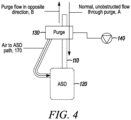
- FIG. 4 is a block diagram of one of the plurality of pipes 110, the aspirated smoke detector 120, and one of the plurality of blowout devices 130 of the system 100 of FIG. 1 with a compressed air path pipe 170 from the blowout device 130 to the aspirated smoke detector 120 in accordance with disclosed embodiments.
- the blowout device 130 can perform the blowout action in the compresses air path pipe 170 by transmitting high velocity compressed air to the aspirated smoke detector 120 via the compressed air path pipe 170 to clear the aspirated smoke detector 120 or specific areas thereof of accumulated particulate and contaminants.
- the blowout device 130 disclosed herein can be a source of compressed air fluidly coupled to the pipe 110 of the aspirating detector system 100 when activated to do so, such as via the activation signal from the aspirated smoke detector 120.
- the blowout device 130 can be activated via a pneumatic valve opening for a period of time to release the compressed air into the pipe 110, thereby purging the pipe, such as of dust and dirt particles.
- a blowout action which is a synonymous with a purge action.
Landscapes
- Physics & Mathematics (AREA)
- General Physics & Mathematics (AREA)
- Business, Economics & Management (AREA)
- Emergency Management (AREA)
- Chemical & Material Sciences (AREA)
- Analytical Chemistry (AREA)
- Engineering & Computer Science (AREA)
- Computer Security & Cryptography (AREA)
- Mechanical Engineering (AREA)
- Fire-Detection Mechanisms (AREA)
- Sampling And Sample Adjustment (AREA)
Description
- The present invention relates generally to a smoke detection system. More particularly, the present invention relates to systems and methods for delaying or activating a blowout device or a purge device in a sampling pipe network of an aspirated smoke detection system.
- In all environments, with the exception of a clean room, a sampling pipe network of an aspirated smoke detection system will experience accumulated particulate and contaminants, such as dust, in sampling holes of pipes in the network and inside of the pipes themselves. Such accumulated particulate and contaminants can restrict the flow of air within the pipes and eventually cause a low flow fault event in the aspirated smoke detection system.
- Accordingly, it is known to activate a blowout device or a purge device in the sampling pipe network, for example, in harsh, dirty, or heavy particulate ridden environments, to perform a blowout action or a purge action that includes sending compressed air through one or more of the pipes in a direction that is opposite to the normal direction of airflow in the pipes. Such blowout devices or purge device performing such blowout actions or purge actions can effectively clear the pipes and any sampling holes therein of any accumulated particulate and contaminants. Indeed, purging the pipes of accumulated particulate and contaminants early and often can increase the effectiveness of the blowout device, the purge device, the blowout action, and the purge action because, over time, the accumulated particulate and contaminants can become attached to the pipes, most notably in humid environments, thereby making them more difficult to remove. Furthermore, purging the pipes of accumulated particulate and contaminants early and often can reduce or avoid low flow fault events.
- However, problems can arise when the blowout device or the purge device is activated at regularly scheduled activation intervals, for example, daily, and performs the blowout action or the purge action when smoke is located in any of the pipes in the network. Indeed, if the blowout device or the purge device clears the pipes of any such smoke, the transport time of the smoke within the pipes can be delayed, and the aspirated smoke detection system can be delayed or inaccurate in detecting the smoke and transmitting signals indicative thereof.
- In view of the above, there is a continuing, ongoing need for improved systems and methods.
-
DE202008006811U1 discloses a free blowing system for the automatic cleaning of fountain pipes of noise absorbing systems, characterized by the fact that in an enclosure a control unit, a functional light with a button, at least one suction control valve(s), pressure valve(s), a compressed air clutch and system heating are provided and form a building block that can be installed by muffing between the noise absorption system and the fountain pipes, with each sensor tube attached to a fountain tube connection connected to the free-blow system, which is connected, on the one hand, via a suction gas valve via the suction tube with the associated suction tube of the room intake system and, on the other hand, by a pressure valve with an internal pressure line, Which is fed via the compressed air clutch by an external factory compressor. Wherein the system is designed to generate a blowout delay when the smoke level within the sampling pipe is "too high" and no smoke alarms have been triggered. This is a specific delay designed to avoid clearing the pipe when smoke is present but is yet to be detected. - Document
EP2 871 620 A1 discloses another example for a smoke detection system. -
-
FIG. 1 is a perspective view of a system in accordance with disclosed embodiments; -
FIG. 2 is a block diagram of one of the plurality of pipes, the aspirated smoke detector, and one of the plurality of blowout devices of the system ofFIG. 1 ; -
FIG. 3 is a block diagram of one of the plurality of pipes, the aspirated smoke detector, and one of the plurality of blowout devices of the system ofFIG. 1 with an in-line filter and a valve in accordance with disclosed embodiments; and -
FIG. 4 is a block diagram of one of the plurality of pipes, the aspirated smoke detector, and one of the plurality of blowout devices of thesystem 100 ofFIG. 1 with a compressed air path pipe from the blowout device to the aspirated smoke detector in accordance with disclosed embodiments. - While this invention is susceptible of an embodiment in many different forms, there are shown in the drawings and will be described herein in detail specific embodiments thereof with the understanding that the present disclosure is to be considered as an exemplification of the principles of the invention. It is not intended to limit the invention to the specific illustrated embodiments.
- Embodiments disclosed herein include systems and methods for delaying or activating a blowout device or a purge device in a sampling pipe network of an aspirated smoke detection system. For example, in accordance with disclosed embodiments, systems and methods disclosed herein can include an isolation delay device that can prevent the blowout device or the purge device from activating and from performing a blowout action or a purge action while the aspirated smoke detection system is experiencing or detecting a triggering event or that can instruct the blowout device or the purge device to activate and perform the blowout action or the purge action responsive to the aspirated smoke detection system experiencing or detecting the triggering event. The isolation delay device disclosed herein can include a relay device, and the isolation delay device disclosed herein can be a programmable, air solenoid operated device. Furthermore, the blowout device or the purge device can be associated with a self-contained air source that the blowout device or the purge device can access to perform the blowout action or the purge action.
- Systems and methods disclosed herein delay the blowout device or the purge device from activating and performing the blowout action or the purge action for a predetermined period of time. After expiration of the predetermined period of time, the blowout device is activated and performs the blowout action or the purge action immediately or in accordance with a regularly scheduled activation interval.
- Systems and methods disclosed herein can delay the blowout device or the purge device from activating and performing the blowout action or the purge action until the aspirated smoke detection system no longer detects the triggering event at which time the blowout device or the purge device can be activated and perform the blowout action or the purge action immediately or in accordance with a regularly scheduled activation interval. The time until the aspirated smoke detection system no longer detects the triggering event can be an indefinite period of time.
- When pipes in the sampling pipe network become dirty enough due to accumulate particulate and contaminants that have not been cleared via the blowout action or the purge action, for example, because the aspirated smoke detection system continues to detect the triggering event and because the blowout device or the purge device is not activated, the aspirated smoke detection system can detect a low flow fault event, for example, when the accumulated particulate causes airflow in the pipes to fall below a predetermined level.
-
FIG. 1 is a perspective view of asystem 100 in accordance with disclosed embodiments. As seen inFIG. 1 , thesystem 100 can include a plurality ofpipes 110 of a sampling pipe network coupled to an aspiratedsmoke detector 120. A respective one of a plurality ofblowout devices 130 can be coupled to each of the plurality ofpipes 110 to perform the blowout action as disclosed herein. It is to be understood that theblowout devices 130 shown within the plurality ofpipes 110 inFIG. 1 are exemplary only and that the location of theblowout devices 130 within the plurality of pipes is not a limitation of the embodiments disclosed herein. Instead, theblowout devices 130 could be located within the middle of or at either end of the plurality ofpipes 130. -
FIG. 2 is a block diagram of one of the plurality ofpipes 110, theaspirated smoke detector 120, and one of the plurality ofblowout devices 130 of thesystem 100 ofFIG. 1 . As seen inFIG. 2 , in normal operation, air can flow through thepipe 110 unobstructed in a first direction A. However, theblowout device 130 can be coupled to adelay device 140 and receive an activation signal or a delay signal from the aspiratedsmoke detector 120 or thedelay device 140 with instructions for performing the blowout action that sends compressed air through thepipe 110 in a second direction B that is opposite the first direction A. - When the triggering event occurs, the aspirated
smoke detector 120 can transmit a triggering event signal to theblowout device 130, and, responsive thereto, theblowout device 130 can transmit a delay signal to thedelay device 140 to prevent or delay thedelay device 140 from transmitting the activation signal to theblowout device 130. Additionally or alternatively, when the triggering event occurs, theaspirated smoke detector 120 can transmit the triggering event signal directly to thedelay device 140, and, responsive thereto, thedelay device 140 can either abstain from or delay transmitting the activation signal to theblowout device 130 or can transmit a delay signal to theblowout device 130 instructing theblowout device 130 to delay activation. Additionally or alternatively, when the triggering event occurs, the aspiratedsmoke detector 120 can transmit the triggering event signal to thedelay device 140, and, responsive thereto, thedelay device 140 can transmit the activation signal to theblowout device 130. Additionally or alternatively, when the triggering event occurs, the aspiratedsmoke detector 120 can transmit the activation signal directly to theblowout device 130. - The triggering event as disclosed herein can include a smoke event, an alert event, or an alarm event, for example, the aspirated
smoke detector 120 detecting an increased smoke signal caused by obscuration in thepipe 110. Responsive thereto, systems and methods can transmit the delay signal to thedelay device 140 or theblowout device 130 or delay transmitting the activation signal to theblowout device 130 to delay the blowout action. - Alternatively, the triggering event as disclosed herein can include the aspirated
smoke detector 120 detecting a predetermined level of particulate within thepipe 110 that indicates an environmental quality that warrants purging. Responsive thereto, systems and methods can transmit the activation signal to delaydevice 140 or theblowout device 130 to instruct theblowout device 130 to perform the blowout action. - Alternatively, the triggering event as disclosed herein can include the aspirated
smoke detector 120 receiving a sensor signal from an endcap sensor associated with thepipe 110 that indicates pipe cleanliness that warrants purging. Responsive thereto, systems and methods can transmit the activation signal to delaydevice 140 or theblowout device 130 to instruct theblowout device 130 to perform the blowout action. - Alternatively, the triggering event as disclosed herein can include the aspirated
smoke detector 120 detecting a predetermined level of air flow velocity or volumetric rate within thepipe 110 that indicates a decrease caused by pipe soiling that warrants purging. Responsive thereto, systems and methods disclosed herein can transmit the activation signal to thedelay device 140 or theblowout device 130 to instruct theblowout device 130 to perform the blowout action. Systems and methods can measure the air flow velocity or the volumetric rate within thepipe 110 within a predetermined period of time after the blowout action, and if there is no improvement in the air flow velocity or the volumetric rate, then systems and methods disclosed herein can transmit a re-activation signal to theblowout device 130 to perform a re-blowout action with increased purge pressure. - Alternatively, the triggering event disclosed herein can include the aspirated
smoke detector 120 receiving a foreign material signal indicative of a foreign material lodged within thepipe 110 or sampling holes therein. In these embodiments, when the triggering event occurs, the aspiratedsmoke detector 120 can transmit the triggering event signal and a dislodge signal to delaydevice 140 or theblowout device 130, and, responsive thereto, theblowout device 130 can transmit high frequency air pulses through thepipe 110 in an attempt to dislodge the foreign material. - Alternatively, the triggering event disclosed herein can include a background signal of the aspirated smoke detector exceeding a predetermined level that warrants purging. Responsive thereto, systems and methods can transmit the activation signal to the
delay device 140 or theblowout device 130 to instruct theblowout device 130 to perform the blowout action. - When the aspirated
smoke detector 120 detects a smoke event immediately after or within a predetermined period of time after the blowout action, systems and methods disclosed herein can reduce any delays in activating theblowout device 130 or raise the level at which the aspiratedsmoke detector 120 detects the triggering event. - To compensate for the delay in the transport time of air within the pipe, systems and methods disclosed herein can temporarily increase the speed of a fan associated with the
pipe 110 for a predetermined period of time after the blowout action or can temporarily raise the level at which the aspiratedsmoke detector 120 detects triggering event. - Systems and methods disclosed herein can create or access an event log in a database device that identifies when past triggering occurred.
- Based on the event log, systems and methods disclosed herein can activate the
blowout device 130 to perform the blowout action only at times when the triggering events are not historically common. For example, systems and methods disclosed herein can base a purge schedule for theblowout device 130 on the event log. - Systems and methods disclosed herein can create or access a flow rate log in a database device that identifies past flow rate values. Based on the flow rate log, systems and methods disclosed herein can identify a purge frequency for the
blowout device 130 and increase the purge frequency when the flow rate log indicates improvement in flow rate values. -
FIG. 3 is a block diagram of one of the plurality ofpipes 110, the aspiratedsmoke detector 120, and one of the plurality ofblowout devices 130 of thesystem 100 ofFIG. 1 with an in-line filter 150 and avalve 160 in accordance with present invention. As seen inFIG. 3 , the in-line filter 150 is associated with thepipe 110 and located upstream of theblowout device 130 in thepipe 110, and thevalve 160 can provide an alternate path pipe for the compressed air that theblowout device 130 transmits in the second direction B during the blowout action. Without thevalve 160, thefilter 150 could not otherwise be placed upstream of theblowout device 130 because thefilter 150 would provide an obstruction to the compressed air flowing in the second direction B during the blowout action and, thus, would be damaged. -
FIG. 4 is a block diagram of one of the plurality ofpipes 110, the aspiratedsmoke detector 120, and one of the plurality ofblowout devices 130 of thesystem 100 ofFIG. 1 with a compressedair path pipe 170 from theblowout device 130 to the aspiratedsmoke detector 120 in accordance with disclosed embodiments. In addition to any of the embodiments disclosed herein, when the triggering event as disclosed herein occurs, for example, when the background signal of the aspirated smoke detector exceeds a predetermined level that warrants purging, theblowout device 130 can perform the blowout action in the compressesair path pipe 170 by transmitting high velocity compressed air to the aspiratedsmoke detector 120 via the compressedair path pipe 170 to clear the aspiratedsmoke detector 120 or specific areas thereof of accumulated particulate and contaminants. - It is to be understood that the
blowout device 130 disclosed herein can be a source of compressed air fluidly coupled to thepipe 110 of the aspiratingdetector system 100 when activated to do so, such as via the activation signal from the aspiratedsmoke detector 120. For example, theblowout device 130 can be activated via a pneumatic valve opening for a period of time to release the compressed air into thepipe 110, thereby purging the pipe, such as of dust and dirt particles. Such a release can be termed a blowout action, which is a synonymous with a purge action. - Although examples have been described in detail above, other modifications are possible. For example, the logic flows described above do not require the particular order described or sequential order to achieve desirable results. Other steps may be provided, steps may be eliminated from the described flows, and other components may be added to or removed from the described systems. Other embodiments may be within the scope of the claims. The alternatives presented in this document may be combined, when not mutually exclusive.
- From the foregoing, it will be observed that numerous variations and modifications may be effected without departing from the scope of the claims. It is to be understood that no limitation with respect to the specific system or method described herein is intended or should be inferred.
Claims (9)
- A system (100) comprising:an aspirated smoke detector (120);a sampling pipe (110) coupled to the aspirated smoke detector (120);a blowout device (130) coupled to the sampling pipe (110); anda delay device (140) coupled to the blowout device (130),wherein, responsive to the aspirated smoke detector (120) detecting a triggering event, the aspirated smoke detector (120) transmits a triggering event signal to the blowout device (130),wherein, responsive to the blowout device (130) receiving the triggering event signal, the blowout device (130) transmits a delay signal to the delay device (140), andwherein, responsive to the delay device (140) receiving the delay signal, the delay device (140) delays the blowout device (130) from performing a blowout action in the sampling pipe by delaying transmission of an activation signal to the blowout device (130); andan in-line filter (150) coupled to the sampling pipe (110) and located upstream of the blowout device (130) in the sampling pipe (110);a valve (160) coupled to the blowout device (130); andan alternate flow path pipe (170) coupled to the valve (160) and to the sampling pipe (110),wherein the blowout action includes the blowout device (130) activating the valve (160) and sending compressed air to the sampling pipe (110) via the alternate flow path pipe (170) while avoiding the in-line filter (150).
- The system of claim 1 wherein the delay device delays the blowout device from performing the blowout action in the sampling pipe for a predetermined period of time.
- The system of claim 1 or claim 2 wherein the delay device delays the blowout device from performing the blowout action in the sampling pipe while the aspirated smoke detector detects the triggering event.
- The system of claim 1 wherein, responsive to the aspirated smoke detector detecting the triggering event, the aspirated smoke detector transmits a triggering event signal to the delay device, and wherein, responsive to the delay device receiving the triggering event signal, the delay device transmits a delay signal to the blowout device instructing the blowout device to delay performing the blowout action in the sampling pipe.
- The system of any of claims 1 to 4 wherein the triggering event includes the aspirated smoke detector detecting a smoke event, an alert event, an alarm event, or an increased smoke signal associated with the sampling pipe.
- The system of any of claims 1 to 5 further comprising a fan coupled to the sampling pipe, wherein the aspirated smoke detector increases a speed of the fan for a predetermined period of time after the blowout device performs the blowout action in the sampling pipe.
- The system of any of claims 1 to 6 wherein the delay device activates the blowout device to perform the blowout action in the sampling pipe according to a blowout schedule, and wherein the blowout schedule is based on an event log or a flow rate log.
- The system of claim 1 wherein the triggering event includes the aspirated smoke detector detecting a predetermined level of particulate, air flow velocity, or volumetric rate within the sampling pipe that warrants purging.
- The system of claim 8 wherein, responsive to the predetermined level of the particulate, the air flow velocity, or the volumetric rate within the sampling pipe after the blowout device performs the blowout action in the sampling pipe, the delay device instructs the blowout device to perform a re-blowout (repeat) action in the sampling pipe.
Applications Claiming Priority (1)
| Application Number | Priority Date | Filing Date | Title |
|---|---|---|---|
| US15/640,770 US10169982B1 (en) | 2017-07-03 | 2017-07-03 | Systems and methods for delaying or activating a blowout device or a purge device in a sampling pipe network of an aspirated smoke detection system |
Publications (2)
| Publication Number | Publication Date |
|---|---|
| EP3428896A1 EP3428896A1 (en) | 2019-01-16 |
| EP3428896B1 true EP3428896B1 (en) | 2024-11-27 |
Family
ID=62597360
Family Applications (1)
| Application Number | Title | Priority Date | Filing Date |
|---|---|---|---|
| EP18176790.6A Active EP3428896B1 (en) | 2017-07-03 | 2018-06-08 | Systems and methods for delaying or activating a blowout device or a purge device in a sampling pipe network of an aspirated smoke detection system |
Country Status (4)
| Country | Link |
|---|---|
| US (1) | US10169982B1 (en) |
| EP (1) | EP3428896B1 (en) |
| CN (1) | CN109201652A (en) |
| CA (1) | CA3007087A1 (en) |
Families Citing this family (7)
| Publication number | Priority date | Publication date | Assignee | Title |
|---|---|---|---|---|
| EP3483585B1 (en) * | 2017-11-13 | 2022-06-29 | Carrier Corporation | Air particulate detection system |
| US11538291B2 (en) | 2020-04-17 | 2022-12-27 | Oshkosh Corporation | Thermal management sensors |
| US11551534B2 (en) * | 2020-04-17 | 2023-01-10 | Oshkosh Corporation | Thermal management controls |
| USD991067S1 (en) * | 2020-10-17 | 2023-07-04 | Honeywell International Inc. | Modular aspirated smoke, gas, and air quality monitoring system device |
| JP7582909B2 (en) * | 2021-06-09 | 2024-11-13 | 株式会社神戸製鋼所 | Suction device, suction method, welding system, welding method, and additive manufacturing method |
| US12431008B2 (en) | 2022-07-18 | 2025-09-30 | Honeywell International Inc. | Performing a self-clean of a fire sensing device |
| US20260104401A1 (en) * | 2024-10-15 | 2026-04-16 | Honeywell International Inc. | Event monitoring and detection device testing |
Citations (1)
| Publication number | Priority date | Publication date | Assignee | Title |
|---|---|---|---|---|
| DE202008006811U1 (en) * | 2007-06-15 | 2009-01-08 | Hacker & Petermann Gmbh | Automatic release system for smoke extraction systems in fire protection |
Family Cites Families (8)
| Publication number | Priority date | Publication date | Assignee | Title |
|---|---|---|---|---|
| US5326025A (en) * | 1993-07-08 | 1994-07-05 | Carrier Corporation | Warm up method for two stage furnace |
| US8098166B2 (en) * | 2009-04-23 | 2012-01-17 | Honeywell International Inc. | Variable air speed aspirating smoke detector |
| CN202283536U (en) * | 2011-01-28 | 2012-06-27 | 北京凡元兴科技有限公司 | Boiler detection guide pipe ash cleaning device |
| JP6438399B2 (en) * | 2012-10-16 | 2018-12-12 | ギャレット・サーマル・システムズ・リミテッドGarrett Thermal Systems Limited | Addressability in particle detection |
| GB2513854A (en) * | 2013-05-04 | 2014-11-12 | Protec Fire Detection Plc | Improvements in and relating to aspirating smoke detectors |
| MY179786A (en) * | 2013-06-03 | 2020-11-14 | Xtralis Technologies Ltd | Particle detection system and related methods |
| AT514912B1 (en) * | 2013-11-07 | 2015-05-15 | Strauss Sicherungsanlagenbau Ges M B H Lab | Smoke detection device |
| US9208671B2 (en) * | 2013-12-05 | 2015-12-08 | Honeywell International Inc. | Redundant input pipe networks in aspirated smoke detectors |
-
2017
- 2017-07-03 US US15/640,770 patent/US10169982B1/en active Active
-
2018
- 2018-06-01 CA CA3007087A patent/CA3007087A1/en active Pending
- 2018-06-08 EP EP18176790.6A patent/EP3428896B1/en active Active
- 2018-06-29 CN CN201810696550.XA patent/CN109201652A/en active Pending
Patent Citations (1)
| Publication number | Priority date | Publication date | Assignee | Title |
|---|---|---|---|---|
| DE202008006811U1 (en) * | 2007-06-15 | 2009-01-08 | Hacker & Petermann Gmbh | Automatic release system for smoke extraction systems in fire protection |
Also Published As
| Publication number | Publication date |
|---|---|
| CN109201652A (en) | 2019-01-15 |
| US10169982B1 (en) | 2019-01-01 |
| CA3007087A1 (en) | 2019-01-03 |
| EP3428896A1 (en) | 2019-01-16 |
| US20190005805A1 (en) | 2019-01-03 |
Similar Documents
| Publication | Publication Date | Title |
|---|---|---|
| US10169982B1 (en) | Systems and methods for delaying or activating a blowout device or a purge device in a sampling pipe network of an aspirated smoke detection system | |
| KR101949949B1 (en) | Filter bypass | |
| RU2733796C2 (en) | Air cleaning device | |
| US10161837B2 (en) | Aspirated particle detection with various flow modifications | |
| KR101845264B1 (en) | Air breathing type fire detector with a dust auto cleaning device | |
| JP6291504B2 (en) | Particle detection system and method | |
| EP4075104B1 (en) | Addressability in particle detection | |
| EP2452323B1 (en) | Chamber condition | |
| KR102008567B1 (en) | Strainer and strainer control system | |
| CN106062446B (en) | Passive Explosion Isolation Valve with Pulse Jet Cleaning | |
| KR101845263B1 (en) | Air breathing type fire detactor | |
| CA2547202A1 (en) | A filter system for an electronic equipment enclosure | |
| KR101333939B1 (en) | Air filltering apparatus of air breathing type air detection device | |
| TWI775950B (en) | Damage detection method of dust collector and filter screen of dust collector | |
| US20170014737A1 (en) | Strainer and Strainer Control System | |
| JP2019070992A (en) | Fire alarm system | |
| CN105473205B (en) | Cleaning process in the equipment of filter of the detection with the arrangement that spatially offsets with respect to each | |
| CA2928284C (en) | Strainer and strainer control system | |
| JPH0446867Y2 (en) | ||
| US20060207228A1 (en) | Autonomously-cleaned conditioning system | |
| JP2024045836A (en) | Fire detectors | |
| JP2546958Y2 (en) | Suction smoke detector | |
| JPH08202966A (en) | Accumulation type fire receiving system and accumulation type fire sensor |
Legal Events
| Date | Code | Title | Description |
|---|---|---|---|
| PUAI | Public reference made under article 153(3) epc to a published international application that has entered the european phase |
Free format text: ORIGINAL CODE: 0009012 |
|
| STAA | Information on the status of an ep patent application or granted ep patent |
Free format text: STATUS: REQUEST FOR EXAMINATION WAS MADE |
|
| 17P | Request for examination filed |
Effective date: 20180608 |
|
| AK | Designated contracting states |
Kind code of ref document: A1 Designated state(s): AL AT BE BG CH CY CZ DE DK EE ES FI FR GB GR HR HU IE IS IT LI LT LU LV MC MK MT NL NO PL PT RO RS SE SI SK SM TR |
|
| AX | Request for extension of the european patent |
Extension state: BA ME |
|
| STAA | Information on the status of an ep patent application or granted ep patent |
Free format text: STATUS: EXAMINATION IS IN PROGRESS |
|
| 17Q | First examination report despatched |
Effective date: 20200507 |
|
| P01 | Opt-out of the competence of the unified patent court (upc) registered |
Effective date: 20230523 |
|
| GRAP | Despatch of communication of intention to grant a patent |
Free format text: ORIGINAL CODE: EPIDOSNIGR1 |
|
| STAA | Information on the status of an ep patent application or granted ep patent |
Free format text: STATUS: GRANT OF PATENT IS INTENDED |
|
| INTG | Intention to grant announced |
Effective date: 20240719 |
|
| GRAS | Grant fee paid |
Free format text: ORIGINAL CODE: EPIDOSNIGR3 |
|
| GRAA | (expected) grant |
Free format text: ORIGINAL CODE: 0009210 |
|
| STAA | Information on the status of an ep patent application or granted ep patent |
Free format text: STATUS: THE PATENT HAS BEEN GRANTED |
|
| AK | Designated contracting states |
Kind code of ref document: B1 Designated state(s): AL AT BE BG CH CY CZ DE DK EE ES FI FR GB GR HR HU IE IS IT LI LT LU LV MC MK MT NL NO PL PT RO RS SE SI SK SM TR |
|
| REG | Reference to a national code |
Ref country code: GB Ref legal event code: FG4D |
|
| REG | Reference to a national code |
Ref country code: CH Ref legal event code: EP |
|
| REG | Reference to a national code |
Ref country code: DE Ref legal event code: R096 Ref document number: 602018076899 Country of ref document: DE |
|
| REG | Reference to a national code |
Ref country code: IE Ref legal event code: FG4D |
|
| REG | Reference to a national code |
Ref country code: LT Ref legal event code: MG9D |
|
| REG | Reference to a national code |
Ref country code: NL Ref legal event code: MP Effective date: 20241127 |
|
| PG25 | Lapsed in a contracting state [announced via postgrant information from national office to epo] |
Ref country code: HR Free format text: LAPSE BECAUSE OF FAILURE TO SUBMIT A TRANSLATION OF THE DESCRIPTION OR TO PAY THE FEE WITHIN THE PRESCRIBED TIME-LIMIT Effective date: 20241127 Ref country code: IS Free format text: LAPSE BECAUSE OF FAILURE TO SUBMIT A TRANSLATION OF THE DESCRIPTION OR TO PAY THE FEE WITHIN THE PRESCRIBED TIME-LIMIT Effective date: 20250327 Ref country code: PT Free format text: LAPSE BECAUSE OF FAILURE TO SUBMIT A TRANSLATION OF THE DESCRIPTION OR TO PAY THE FEE WITHIN THE PRESCRIBED TIME-LIMIT Effective date: 20250327 |
|
| PG25 | Lapsed in a contracting state [announced via postgrant information from national office to epo] |
Ref country code: FI Free format text: LAPSE BECAUSE OF FAILURE TO SUBMIT A TRANSLATION OF THE DESCRIPTION OR TO PAY THE FEE WITHIN THE PRESCRIBED TIME-LIMIT Effective date: 20241127 Ref country code: NL Free format text: LAPSE BECAUSE OF FAILURE TO SUBMIT A TRANSLATION OF THE DESCRIPTION OR TO PAY THE FEE WITHIN THE PRESCRIBED TIME-LIMIT Effective date: 20241127 |
|
| REG | Reference to a national code |
Ref country code: AT Ref legal event code: MK05 Ref document number: 1746492 Country of ref document: AT Kind code of ref document: T Effective date: 20241127 |
|
| PG25 | Lapsed in a contracting state [announced via postgrant information from national office to epo] |
Ref country code: BG Free format text: LAPSE BECAUSE OF FAILURE TO SUBMIT A TRANSLATION OF THE DESCRIPTION OR TO PAY THE FEE WITHIN THE PRESCRIBED TIME-LIMIT Effective date: 20241127 |
|
| PG25 | Lapsed in a contracting state [announced via postgrant information from national office to epo] |
Ref country code: ES Free format text: LAPSE BECAUSE OF FAILURE TO SUBMIT A TRANSLATION OF THE DESCRIPTION OR TO PAY THE FEE WITHIN THE PRESCRIBED TIME-LIMIT Effective date: 20241127 |
|
| PG25 | Lapsed in a contracting state [announced via postgrant information from national office to epo] |
Ref country code: NO Free format text: LAPSE BECAUSE OF FAILURE TO SUBMIT A TRANSLATION OF THE DESCRIPTION OR TO PAY THE FEE WITHIN THE PRESCRIBED TIME-LIMIT Effective date: 20250227 |
|
| PG25 | Lapsed in a contracting state [announced via postgrant information from national office to epo] |
Ref country code: LV Free format text: LAPSE BECAUSE OF FAILURE TO SUBMIT A TRANSLATION OF THE DESCRIPTION OR TO PAY THE FEE WITHIN THE PRESCRIBED TIME-LIMIT Effective date: 20241127 Ref country code: AT Free format text: LAPSE BECAUSE OF FAILURE TO SUBMIT A TRANSLATION OF THE DESCRIPTION OR TO PAY THE FEE WITHIN THE PRESCRIBED TIME-LIMIT Effective date: 20241127 Ref country code: GR Free format text: LAPSE BECAUSE OF FAILURE TO SUBMIT A TRANSLATION OF THE DESCRIPTION OR TO PAY THE FEE WITHIN THE PRESCRIBED TIME-LIMIT Effective date: 20250228 |
|
| PG25 | Lapsed in a contracting state [announced via postgrant information from national office to epo] |
Ref country code: PL Free format text: LAPSE BECAUSE OF FAILURE TO SUBMIT A TRANSLATION OF THE DESCRIPTION OR TO PAY THE FEE WITHIN THE PRESCRIBED TIME-LIMIT Effective date: 20241127 |
|
| PG25 | Lapsed in a contracting state [announced via postgrant information from national office to epo] |
Ref country code: RS Free format text: LAPSE BECAUSE OF FAILURE TO SUBMIT A TRANSLATION OF THE DESCRIPTION OR TO PAY THE FEE WITHIN THE PRESCRIBED TIME-LIMIT Effective date: 20250227 |
|
| PG25 | Lapsed in a contracting state [announced via postgrant information from national office to epo] |
Ref country code: SM Free format text: LAPSE BECAUSE OF FAILURE TO SUBMIT A TRANSLATION OF THE DESCRIPTION OR TO PAY THE FEE WITHIN THE PRESCRIBED TIME-LIMIT Effective date: 20241127 |
|
| PGFP | Annual fee paid to national office [announced via postgrant information from national office to epo] |
Ref country code: DE Payment date: 20250626 Year of fee payment: 8 |
|
| PG25 | Lapsed in a contracting state [announced via postgrant information from national office to epo] |
Ref country code: DK Free format text: LAPSE BECAUSE OF FAILURE TO SUBMIT A TRANSLATION OF THE DESCRIPTION OR TO PAY THE FEE WITHIN THE PRESCRIBED TIME-LIMIT Effective date: 20241127 |
|
| PGFP | Annual fee paid to national office [announced via postgrant information from national office to epo] |
Ref country code: GB Payment date: 20250617 Year of fee payment: 8 |
|
| PG25 | Lapsed in a contracting state [announced via postgrant information from national office to epo] |
Ref country code: EE Free format text: LAPSE BECAUSE OF FAILURE TO SUBMIT A TRANSLATION OF THE DESCRIPTION OR TO PAY THE FEE WITHIN THE PRESCRIBED TIME-LIMIT Effective date: 20241127 |
|
| PGFP | Annual fee paid to national office [announced via postgrant information from national office to epo] |
Ref country code: FR Payment date: 20250624 Year of fee payment: 8 |
|
| PG25 | Lapsed in a contracting state [announced via postgrant information from national office to epo] |
Ref country code: RO Free format text: LAPSE BECAUSE OF FAILURE TO SUBMIT A TRANSLATION OF THE DESCRIPTION OR TO PAY THE FEE WITHIN THE PRESCRIBED TIME-LIMIT Effective date: 20241127 |
|
| PG25 | Lapsed in a contracting state [announced via postgrant information from national office to epo] |
Ref country code: SK Free format text: LAPSE BECAUSE OF FAILURE TO SUBMIT A TRANSLATION OF THE DESCRIPTION OR TO PAY THE FEE WITHIN THE PRESCRIBED TIME-LIMIT Effective date: 20241127 |
|
| PG25 | Lapsed in a contracting state [announced via postgrant information from national office to epo] |
Ref country code: CZ Free format text: LAPSE BECAUSE OF FAILURE TO SUBMIT A TRANSLATION OF THE DESCRIPTION OR TO PAY THE FEE WITHIN THE PRESCRIBED TIME-LIMIT Effective date: 20241127 |
|
| PG25 | Lapsed in a contracting state [announced via postgrant information from national office to epo] |
Ref country code: IT Free format text: LAPSE BECAUSE OF FAILURE TO SUBMIT A TRANSLATION OF THE DESCRIPTION OR TO PAY THE FEE WITHIN THE PRESCRIBED TIME-LIMIT Effective date: 20241127 |
|
| REG | Reference to a national code |
Ref country code: DE Ref legal event code: R097 Ref document number: 602018076899 Country of ref document: DE |
|
| PG25 | Lapsed in a contracting state [announced via postgrant information from national office to epo] |
Ref country code: SE Free format text: LAPSE BECAUSE OF FAILURE TO SUBMIT A TRANSLATION OF THE DESCRIPTION OR TO PAY THE FEE WITHIN THE PRESCRIBED TIME-LIMIT Effective date: 20241127 |
|
| PLBE | No opposition filed within time limit |
Free format text: ORIGINAL CODE: 0009261 |
|
| STAA | Information on the status of an ep patent application or granted ep patent |
Free format text: STATUS: NO OPPOSITION FILED WITHIN TIME LIMIT |
|
| REG | Reference to a national code |
Ref country code: CH Ref legal event code: L10 Free format text: ST27 STATUS EVENT CODE: U-0-0-L10-L00 (AS PROVIDED BY THE NATIONAL OFFICE) Effective date: 20251008 |
|
| 26N | No opposition filed |
Effective date: 20250828 |
|
| REG | Reference to a national code |
Ref country code: CH Ref legal event code: H13 Free format text: ST27 STATUS EVENT CODE: U-0-0-H10-H13 (AS PROVIDED BY THE NATIONAL OFFICE) Effective date: 20260127 |
|
| PG25 | Lapsed in a contracting state [announced via postgrant information from national office to epo] |
Ref country code: MC Free format text: LAPSE BECAUSE OF FAILURE TO SUBMIT A TRANSLATION OF THE DESCRIPTION OR TO PAY THE FEE WITHIN THE PRESCRIBED TIME-LIMIT Effective date: 20241127 |
|
| PG25 | Lapsed in a contracting state [announced via postgrant information from national office to epo] |
Ref country code: LU Free format text: LAPSE BECAUSE OF NON-PAYMENT OF DUE FEES Effective date: 20250608 |
|
| REG | Reference to a national code |
Ref country code: BE Ref legal event code: MM Effective date: 20250630 |
|
| PG25 | Lapsed in a contracting state [announced via postgrant information from national office to epo] |
Ref country code: IE Free format text: LAPSE BECAUSE OF NON-PAYMENT OF DUE FEES Effective date: 20250608 |
|
| PG25 | Lapsed in a contracting state [announced via postgrant information from national office to epo] |
Ref country code: BE Free format text: LAPSE BECAUSE OF NON-PAYMENT OF DUE FEES Effective date: 20250630 |
|
| PG25 | Lapsed in a contracting state [announced via postgrant information from national office to epo] |
Ref country code: CH Free format text: LAPSE BECAUSE OF NON-PAYMENT OF DUE FEES Effective date: 20250630 |