EP3428886A1 - Ray tracing system architectures and methods - Google Patents
Ray tracing system architectures and methods Download PDFInfo
- Publication number
- EP3428886A1 EP3428886A1 EP18189407.2A EP18189407A EP3428886A1 EP 3428886 A1 EP3428886 A1 EP 3428886A1 EP 18189407 A EP18189407 A EP 18189407A EP 3428886 A1 EP3428886 A1 EP 3428886A1
- Authority
- EP
- European Patent Office
- Prior art keywords
- rays
- ray
- intersection
- data
- memory
- Prior art date
- Legal status (The legal status is an assumption and is not a legal conclusion. Google has not performed a legal analysis and makes no representation as to the accuracy of the status listed.)
- Granted
Links
- 238000000034 method Methods 0.000 title claims description 67
- 239000000872 buffer Substances 0.000 claims abstract description 84
- 230000001133 acceleration Effects 0.000 claims abstract description 73
- 238000012360 testing method Methods 0.000 claims description 232
- 230000015654 memory Effects 0.000 claims description 94
- 238000012545 processing Methods 0.000 claims description 51
- 230000008569 process Effects 0.000 description 23
- 230000006870 function Effects 0.000 description 18
- 238000009877 rendering Methods 0.000 description 18
- 230000003139 buffering effect Effects 0.000 description 12
- 238000007726 management method Methods 0.000 description 11
- 230000003936 working memory Effects 0.000 description 10
- 238000013459 approach Methods 0.000 description 9
- 238000003860 storage Methods 0.000 description 8
- 230000000694 effects Effects 0.000 description 5
- 238000011094 buffer selection Methods 0.000 description 4
- 238000004891 communication Methods 0.000 description 4
- 230000009471 action Effects 0.000 description 3
- 230000006399 behavior Effects 0.000 description 3
- 230000008901 benefit Effects 0.000 description 3
- 230000005540 biological transmission Effects 0.000 description 3
- 230000000977 initiatory effect Effects 0.000 description 3
- 230000008520 organization Effects 0.000 description 3
- 238000004364 calculation method Methods 0.000 description 2
- 230000008859 change Effects 0.000 description 2
- 238000013500 data storage Methods 0.000 description 2
- 238000009826 distribution Methods 0.000 description 2
- 238000003384 imaging method Methods 0.000 description 2
- 230000033001 locomotion Effects 0.000 description 2
- 238000002360 preparation method Methods 0.000 description 2
- 230000000644 propagated effect Effects 0.000 description 2
- 229920006395 saturated elastomer Polymers 0.000 description 2
- 230000009466 transformation Effects 0.000 description 2
- 230000001131 transforming effect Effects 0.000 description 2
- 230000002776 aggregation Effects 0.000 description 1
- 238000004220 aggregation Methods 0.000 description 1
- 238000004458 analytical method Methods 0.000 description 1
- 238000003491 array Methods 0.000 description 1
- 239000011365 complex material Substances 0.000 description 1
- 238000001514 detection method Methods 0.000 description 1
- 238000010586 diagram Methods 0.000 description 1
- 238000001125 extrusion Methods 0.000 description 1
- 230000006872 improvement Effects 0.000 description 1
- 238000012361 intermediate testing Methods 0.000 description 1
- 230000001788 irregular Effects 0.000 description 1
- 238000013507 mapping Methods 0.000 description 1
- 230000000873 masking effect Effects 0.000 description 1
- 238000012986 modification Methods 0.000 description 1
- 230000004048 modification Effects 0.000 description 1
- 230000003287 optical effect Effects 0.000 description 1
- 230000002093 peripheral effect Effects 0.000 description 1
- 230000002250 progressing effect Effects 0.000 description 1
- 230000004044 response Effects 0.000 description 1
- 230000000717 retained effect Effects 0.000 description 1
- 238000000844 transformation Methods 0.000 description 1
- 230000001052 transient effect Effects 0.000 description 1
Images


Classifications
-
- G—PHYSICS
- G06—COMPUTING; CALCULATING OR COUNTING
- G06T—IMAGE DATA PROCESSING OR GENERATION, IN GENERAL
- G06T15/00—3D [Three Dimensional] image rendering
- G06T15/06—Ray-tracing
-
- G—PHYSICS
- G06—COMPUTING; CALCULATING OR COUNTING
- G06T—IMAGE DATA PROCESSING OR GENERATION, IN GENERAL
- G06T1/00—General purpose image data processing
- G06T1/60—Memory management
-
- G—PHYSICS
- G06—COMPUTING; CALCULATING OR COUNTING
- G06T—IMAGE DATA PROCESSING OR GENERATION, IN GENERAL
- G06T15/00—3D [Three Dimensional] image rendering
- G06T15/08—Volume rendering
-
- G—PHYSICS
- G06—COMPUTING; CALCULATING OR COUNTING
- G06T—IMAGE DATA PROCESSING OR GENERATION, IN GENERAL
- G06T15/00—3D [Three Dimensional] image rendering
- G06T15/50—Lighting effects
- G06T15/80—Shading
-
- G—PHYSICS
- G06—COMPUTING; CALCULATING OR COUNTING
- G06T—IMAGE DATA PROCESSING OR GENERATION, IN GENERAL
- G06T2215/00—Indexing scheme for image rendering
- G06T2215/12—Shadow map, environment map
-
- G—PHYSICS
- G09—EDUCATION; CRYPTOGRAPHY; DISPLAY; ADVERTISING; SEALS
- G09G—ARRANGEMENTS OR CIRCUITS FOR CONTROL OF INDICATING DEVICES USING STATIC MEANS TO PRESENT VARIABLE INFORMATION
- G09G2360/00—Aspects of the architecture of display systems
- G09G2360/12—Frame memory handling
- G09G2360/121—Frame memory handling using a cache memory
-
- G—PHYSICS
- G09—EDUCATION; CRYPTOGRAPHY; DISPLAY; ADVERTISING; SEALS
- G09G—ARRANGEMENTS OR CIRCUITS FOR CONTROL OF INDICATING DEVICES USING STATIC MEANS TO PRESENT VARIABLE INFORMATION
- G09G2370/00—Aspects of data communication
- G09G2370/10—Use of a protocol of communication by packets in interfaces along the display data pipeline
-
- G—PHYSICS
- G09—EDUCATION; CRYPTOGRAPHY; DISPLAY; ADVERTISING; SEALS
- G09G—ARRANGEMENTS OR CIRCUITS FOR CONTROL OF INDICATING DEVICES USING STATIC MEANS TO PRESENT VARIABLE INFORMATION
- G09G5/00—Control arrangements or circuits for visual indicators common to cathode-ray tube indicators and other visual indicators
- G09G5/003—Details of a display terminal, the details relating to the control arrangement of the display terminal and to the interfaces thereto
- G09G5/006—Details of the interface to the display terminal
-
- G—PHYSICS
- G09—EDUCATION; CRYPTOGRAPHY; DISPLAY; ADVERTISING; SEALS
- G09G—ARRANGEMENTS OR CIRCUITS FOR CONTROL OF INDICATING DEVICES USING STATIC MEANS TO PRESENT VARIABLE INFORMATION
- G09G5/00—Control arrangements or circuits for visual indicators common to cathode-ray tube indicators and other visual indicators
- G09G5/36—Control arrangements or circuits for visual indicators common to cathode-ray tube indicators and other visual indicators characterised by the display of a graphic pattern, e.g. using an all-points-addressable [APA] memory
- G09G5/39—Control of the bit-mapped memory
- G09G5/393—Arrangements for updating the contents of the bit-mapped memory
Definitions
- the following relates to rendering, using ray tracing, two-dimensional representations of three-dimensional scenes composed of shapes, and more particularly to systems, methods, and means for intersection testing of rays in 3-D scenes.
- Ray tracing usually involves obtaining a scene description composed of geometric shapes, which describe surfaces of structures in the scene, and can be called primitives.
- a common primitive shape is a triangle.
- Virtual rays of light are traced into the scene from a view point ("a camera"); each ray is issued to travel through a respective pixel of the 2-D representation, on which that ray can have an effect.
- the rays are tested for intersection with scene primitives to identify a first intersected primitive for each ray, if any.
- a shader associated with that primitive determines what happens next. For example, if the primitive is part of a mirror, then a reflection ray is issued to determine whether light is hitting the intersected point from a luminaire, or in more complicated situations, subsurface reflection, and scattering can be modeled, which may cause issuance of different rays to be intersected tested. By further example, if a surface of an object were rough, not smooth, then a shader for that object may issue rays to model a diffuse reflection on that surface. As such, finding an intersection between a ray and a primitive is a first step in determining whether and what kind of light energy may reach a pixel by virtue of a given ray, since what light is hitting that primitive still needs to be determined.
- Ray tracing can be naively parallelized by providing many processing resources that operate on different portions of pixels of a 2-D scene to be rendered.
- simply providing more computation capability does not necessarily allow a suitable scaling of ray tracing speed and efficiency.
- One reason for this is that such parallelization does not account for how data composing the scene, or an acceleration structure that increases tracing efficiency can be accessed in an efficient manner.
- a variety of improvements to ray tracing architectures remain to be provided.
- a ray tracing system comprises an input for receiving information for rays that have been found to intersect a primitive composing a 3-D scene being ray traced.
- the system also comprises a plurality of buffers.
- a sorter is coupled to the input and to the plurality of buffers.
- the sorter is configured for dividing the received information among the plurality of buffers by grouping together, in respective buffers, information for rays that are expected to be shaded using one or more of common shader code and common shader data.
- the system also comprise an output for outputting contents of a selected buffer to a computation resource to be configured for shading intersections for the rays for which information is stored in the selected buffer.
- the information for each ray comprises an identifier for that ray.
- identification information for one or more primitives that may have been intersected can be stored in association with identification information for the potentially-intersecting ray.
- Other information characterizing a closest detected intersection also can be stored in the buffers, or retrieved from a memory upon buffer selection.
- the output can provide the information from the buffer as a stream, such as a stream of ray identifiers and other information associated with those ray identifiers, as applicable.
- primitives potentially intersected by a given ray can have respective identifiers. These identifiers can be used to determine an object of which those primitives are a part. In turn, commonality of object can be used to infer commonality of one or more of shader code and shader data to be used during shading of intersections involving different rays.
- objects can be associated with discrete shader code modules, and in some embodiments, primitives can each be associated with shader code modules, or portions thereof.
- Ray tracing systems also can comprise the computation resource to be configured for shading ray intersections, which can be configured to arrange for storage of retrieved shading data in a cache for local access during shading of the indicated intersections for the rays from the selected buffer.
- the computation resource to be configured for shading intersections also can be configured for performing final intersection testing of a plurality of identified primitives, which may have been intersected by a given ray to identify an actual intersection of the given ray to be shaded.
- Such functionality also can be implemented by a computation resource intermediating between the intersecting testing and the shading. Any such ray tracing systems can output ray information by streaming ray identifiers from the selected buffer to the computation resource for shading their respective intersections.
- exemplary ray tracing systems can comprise an intersection testing resource with an intersection testing input for receiving identifiers for rays that are to begin intersection testing in the intersection testing resource.
- ray identifiers can be received from a plurality of shader code modules, and would be outputted in blocks to begin intersection testing, and preferably concurrent testing, of rays identified by those ray identifiers.
- concurrent testing can be performed by systems that comprise an intersection testing resource that comprises a plurality of test cells, and is configured for splitting blocks of ray identifiers among the test cells for concurrent testing of the identified rays.
- the input is configured for gathering identifiers of rays outputted from the plurality of the test cells as the ray information.
- One example is a method that comprises providing data defining objects composing a 3-D scene, where the data comprising definition data for primitives that compose the objects.
- the method also comprises defining a plurality of rays to be processed, the processing for each ray comprising identifying a respective closest intersection, if any, with the primitives and shading such an intersection by executing one or more code modules.
- the method also comprise outputting groupings of information for rays for which a closest intersection has been identified, where the groupings were formed based on one or more of expected commonality of code modules and expected commonality of data to be used during shading of intersections for the identified rays.
- the outputting comprises storing the ray information for the groupings in an output-pending buffer.
- the ray information can comprise ray identifiers, identifiers for one or more primitives that may be have been intersected by each identified ray, and in some embodiments, only a primitive that was first and actually intersected by each ray.
- the identifying a respective closest intersection can comprise producing associations between identifiers for intersected primitives and identifiers for rays that have intersected those primitives.
- the primitive identifiers can be used to determine expected commonality of code modules to be executed for shading intersections involving those primitives.
- Such exemplary methods also can further comprise storing definition data for the plurality of rays in a distributed memory, and performing the identifying of respective closest intersections for the rays of the plurality in a plurality of test cells.
- Each test cell can have an allocated port to the distributed memory.
- the distributed memory also can store data identifying a current closest detected intersection for each of the rays..
- a controller can make collections of rays, at least some of the collections associated with respective scene objects composing the 3-D scene.
- the collections can be formed both for intersection testing and shading. In some example,s the collections formed for shading can be limited only to rays for which an actual intersection has been identified.
- collections can be formed from leaf nodes of an acceleration structure, where those leaf nodes have been defined to bound primitives of a common scene object (such leaf nodes also can be selected or defined based on a determined commonality of one or more of shader code and shader data).
- Other aspects comprise a method for providing a ray tracing system, which comprises providing an intersection testing resource operable for concurrent intersection testing of a plurality of rays in a 3-D scene, which results in identification of detected valid intersections for at least some of the plurality of rays.
- the method also comprises providing an intersection shading resource for configuration to run shading code for shading detected valid ray intersections, and providing for communication between the intersection testing resource and the shading resource.
- the communication can be implemented by outputting one or more groupings of information for the detected intersections, the groupings determined based on an expectation that each intersection of each group will be shaded with one or more of common shading code and common shading data.
- the groupings can be formed by sorting rays based on identification information for respective primitives they intersected.
- Such methods also cancomprise providing for buffering of new ray data from the shading resource to the intersection testing resource.
- the buffering of new ray data can comprise collecting new ray data from a plurality of shader code modules for initiation of concurrent intersection testing of those new rays.
- Such methods also can comprise providing functionality, such as a control module function, for scheduling one or more threads to function as the shading resource for executing the common shading code.
- Another example system comprises a plurality of intersection testers, each operable for testing a ray for intersection with a shape defined by shape data provided to it.
- the ray to be tested by each of the intersection testers is defined by data locally accessible by that intersection tester.
- the system comprises a controller for collecting, from the intersection testers, associations between elements of an acceleration structure bounding primitives composing the 3-D scene and identifiers for rays that have been determined to intersect each element.
- the system also comprises an interface between the controller and the plurality of intersection testers.
- the interface can receive a group of identifiers for rays to be tested, and disperse the ray identifiers among the intersections testers, based on which of the intersection testers can locally access definition data for each ray.
- Such an interface can abstract the plurality of testers from the controller, such that the testers do not need to be aware of the source or nature of the data they test.
- results from the test cells are abstracted by the interface, such that the controller does not need to poll or otherwise query particular test cells for results of particular tests.
- such a system can comprise a computing resource for shading intersections between rays and primitives composing the 3-D scene.
- the shading can result in new rays to be intersection tested.
- the system also can comprise a second interface abstracting the controller and the plurality of testers from the shading computing resource.
- the second interface is operable for receiving definition data for the new rays, and assigning respective identifiers for the new rays by which each of the new rays is to be identified during tracing.
- test cells of such a system can be organized into subsets to form a plurality of test regions.
- Each test region can comprise a private memory for storing a respective subset of definition data for rays being intersection tested with objects of a 3-D scene.
- the first interface can be operable to receive a packet comprising a plurality of ray identifiers from the controller.
- Each ray identifier is mappable to one of the rays for which definition data is stored in the private memories of the test regions, and used in determining which test region includes definition data for each ray identified in the packet.
- Another aspect comprises a system for querying a database of information, with an imposed hierarchical acceleration structure that has elements grouping subsets of the information.
- the system comprises an input buffer, and a memory for storing data defining testing requests remaining to be satisfied from the database.
- the system also comprises testing logic for performing concurrent testing of discrete queries (i.e., queries that when submitted had no known relationship to each other) whether elements of the acceleration structure meet criteria defined by the query.
- the discrete queries are collected into collections based on outputs of the testing.
- the testing resources are scheduled for further querying by scheduling collections for test, such that discrete queries can be satisfied out of an order submitted.
- One result of such queries is identification of a code module to be executed based on one or more parameters defined in the query. Results also can include identifying other data to be used during execution of the code module. In some cases, the code module execution can result in more queries to the database.
- Still other aspects comprise a method of tracing rays in a 3-D scene.
- the method comprises dispersing rays being traced in the scene among a plurality of elements of a hierarchical acceleration structure. Each element bounds a respective sub-portion of the 3-D scene, forming respective collections of rays that have been determined to intersect each of the elements.
- the method also comprises selecting rays for further dispersal based on selecting collections of which they are members. The selecting accounts for both respective numbers of rays in the collections and respective positions of the elements in the hierarchical acceleration structure to which the collections are associated.
- Systems and methods implemented in the above systems can operate through the described interfaces by maintaining a credit count indicative of numbers of rays (and more broadly, queries) sent to the traversal unit and numbers of rays for which results are returned from the traversal unit.
- the credit count can be used in determining when to send new rays (queries) to the traversal unit.
- the method also comprises accepting commands from an intersection testing controller that maintains status for rays that are stored in the allocated memory portion to provide more rays for storage in the memory portion from a larger pool of rays that await intersection testing.
- the method comprises representing definition data of an element of an acceleration structure with using a first number of bits responsive to the element being greater than a threshold in size.
- the method also comprises using a second number of bits, larger than the first, for representing the definition data responsive to the element being less than or equal to the threshold in size.
- the testing can proceed with the higher precision format if the element is smaller than a threshold in size; and with the ray using a lower precision format if the element is greater than or equal to the threshold in size.
- a primitive e . g ., coordinates for three vertices of a triangle
- data representative of that ray is referenced, as well as the concept of the ray in the scene.
- FIG.1 illustrates a simplified scene setup, in which a 2-D plane 175 is disposed between a camera 105 and a scene 150, comprising objects 110, 115 and a light 120.
- a camera ray 130 is emitted from camera 105 (such using program code descriptive of behaviors of the camera). It is determined through intersection testing that ray 130 intersects object 110.
- a ray 131 is emitted by a shader (e.g., program code and data describing behavior for an object or surface) associated with object 110.
- object 110 may have a mirrored surface, and as such the shader for it would generate ray 131 to test reflection at an angle that ray 130 was incident on object 110. It then is determined that ray 131 hits object 115.
- a shader associated with object 115 is shown to have similar behavior to that of the shader for object 110, emitting a ray 132 to test whether light is incident on object 115 at an angle that could have traveled on the path of ray 131. Ray 132 is determined to intersect light 120.
- FIG.1 was necessarily grossly simplified. Many factors adding computational cost to a more realistic ray tracing scene include that the resolution of the 2-D representation to be rendered can be high, such as a full HD resolution of 1920x1080 pixels (over 2 million pixels). Each pixel of the scene can have many rays emitted from the camera that are associated with it. Thus, rendering such a scene can involve initially testing many millions of camera rays alone, followed by much higher numbers of rays that are emitted by shaders identified based on object intersections with camera rays, and in turn rays subsequently emitted by shaders.
- Shaders can involve substantial computation and emission of further rays that test various conditions. For example, shaders can perform diffuse lighting tests, such as Monte Carlo diffuse lighting, which involves emission of a number of rays to test ambient lighting conditions. Shaders may emit rays to test whether an intersection point is shadowed by another object for known light sources in the scene. Shaders also can model complex materials characteristics, such as subsurface scattering for skin, reflection, refraction, and so on. Each of these functions can involve emission of rays that need to be intersection tested in the scene. Thus, rendering a full HD high resolution 2-D representation of a complex scene can involve intersection testing of hundreds of millions or more rays.
- this example shows that a ray is tested for intersection in a scene. If it is found to intersect an object (e.g., a primitive), then a shader associated with that object can be identified and executed. That shader can in turn emit more rays to be intersection tested.
- the number and type of rays that shader emits typically depends both on characteristics of the intersecting ray and also on the effects that the shader is implementing.
- FIG. 2 illustrates an example system 200 for use in rendering a scene with ray tracing techniques.
- System 200 comprises a main memory 205, in which is stored data 206 for intersection shading (e.g., shader code, textures, procedural geometry, and so on), primitives and acceleration shape elements (e.g., triangles, triangle strips, vertexes, bounding spheres, axis aligned bounding box or k-d tree definitions, and so on), and a master copy of data 208 defining the rays currently being tested for intersection in the scene.
- the main memory 205 communicates with an intersection processing resource 202, in which shaders for identified ray/primitive intersections can be run.
- the communication between memory 205 and intersection processing resource 202 is shown to include link 221 for providing intersection shading data 206 from memory 205, and link 222 for providing primitive data from memory 205.
- intersection processing resource 202 operates to shade intersections identified by an intersection testing resource 210.
- Intersection testing resource 210 is directed to test rays by a controller 203.
- Controller 203 provides indications of rays to be tested to intersection testing resource 210 via a link 225; preferably controller 203 indicates rays to be tested by providing an identifier, which can be related to a memory location storing data defining that ray resident in cache 211. In that preferred situation, definition data for the rays to be tested is obtained/received via link 228 from ray definition cache 211.
- Intermediate testing results of a current closest detected primitive intersection can be stored with ray definition data in cache 211 (i.e., in some implementations, rays can intersect primitives, but if the rays are not tested in an order that the ray traverses the scene, then a farther intersection can be detected prior to a real, closest intersection, which is generally the only intersection of interest).
- Intersection testing resource 210 receives primitive and acceleration shape data from memory 205 through link 220.
- Controller 203 arranges for processing of these possible closest indicated intersections in intersection processing resources 202. Controller 203 receives data defining rays to be intersection tested that have been created by the shaders executing on resources 202. In FIG. 2 , link 226 is depicted for receiving such new ray data, while link 227 is depicted for providing information to instantiate shading of a particular intersection that was provided from link 224. Link 227 can comprise providing, or fetching code and data defining a shader, or otherwise directing intersection processing resources to perform such fetching from memory 205.
- Controller 203 also manages the master copy of ray definition data 208 stored in memory 205, and can store data defining new rays in memory 205 via link 223. Data stored in memory 205 defining rays that have completed intersection testing are replaced by data defining new rays instantiated by the shaders.
- intersection testing resources 210 and the intersection processing resources 202 can be implemented on a processing platform 201 and can comprise threads of processing on a multithreaded processor, or threads executing on separate cores of a multiple core processor, or physically separate processors, each potentially with multiple cores. Each thread can execute instructions from computer executable code obtained from memory 205 or from another source.
- memory 205 may be implemented as dynamic RAM accessible through a memory controller (not separately depicted) by processor 201.
- Cache 211 may be implemented in various levels, such as a private or semi-private L1 cache owned by one or more cores in a multiple core processor, L2 caches and L3 that may be shared among cores and/or among processors.
- ray definition data stored in cache 211 is protected from being overwritten by normal cache management algorithms, such as Least Recently Used, and the like. Instead, it is preferred that controller 203 manage the ray definition data stored in cache 211, as a subset of the ray definition data master 208. Such ray definition data in cache 211 can be updated from master 208 via link 229.
- the links 220-229 illustrated may be implemented based on the implementation of the cache 211, memory 205, and the intersection testing 210 and processing 210 resources.
- intersection testing resource 210 performs more fixed-function types of computation, in that it tests rays for intersection against shapes, usually either a primitive shape or an acceleration shape element, which bounds a selection of primitives defining the scene.
- the types of computation to be performed during shading is more general, in that shaders can perform a variety of computation, access, manipulate and create various data, and so on. Therefore, in some circumstances, intersection testing resources 210 can be implemented beneficially with more fixed-function processing, while resources 202 can often be implemented beneficially on a more general purpose computing platform. Therefore, in some circumstances, intersection testing resources 210 can be provided as an acceleration function, add-in card, co-processor, or the like that either is fixed-function or can be programmed with the expectation that the programming will not change often during the rendering of a scene.
- Implementations according to this disclosure need not have all characteristics shown in example system 200.
- rays are indicated for intersection testing by providing ray identifiers, separate from data defining the rays to intersection testing resource 210, which is optional.
- various links where illustrated, but depending on the implementation, not all such links may be necessary or desired.
- FIG. 2 depicts a system wherein computation resources can be provided for intersection testing, and they therefore produce indications of detected intersections. These intersection testing resources can operate concurrently with computation resources that are executing shaders for detected intersections. The shaders emit new rays for intersection testing, which are taken up for testing by the intersection testing resources.
- FIG. 3 includes a block diagram of an example of an intersection testing resource 210 that includes a plurality of test cells 310a-310n and 340a-340n.
- Acceleration structure elements are illustrated as being sourced from storage 207 (elements of an acceleration structure can be defined by definition data contained in a memory that also contains data defining primitives of the scene.
- ITU 303 also comprises collection management logic 303 and collection buffer 361.
- Collection buffer 361 and ray data 211 can be stored in a memory 340 that can receive ray data from memory 139 (for example).
- Collection buffer 361 maintains ray references associated with GAD elements.
- Collection management 303 maintains those collections based on intersection information from test cells.
- Collection management 303 also can initiate the fetching of primitives and GAD elements from memory 207 for testing ray collections.
- ITU 303 returns indications of identified intersections, which can be buffered in output buffer 375 for ultimate provision via results interface 225 to intersection processing 202.
- Indications may comprise information sufficient to identify a ray and a shape, such as a primitive, which the ray was determined, within a given degree of precision, to intersect.
- the degree of precision can include that a given bounding element bounding one or more primitives was found to be intersected by one or more rays, but each primitive has not yet been finally intersection tested with such rays.
- ITU 303 can be viewed as a function or a utility that can be called through a control process or driver that provides ITU 303 with rays and geometric shapes against which the rays would be tested for intersection.
- ITU 303 can be fed information through a driver, which can be considered in one aspect to be a process that interfaces ITU 303 with other rendering processes, such as shading, and initial ray generation functions.
- ITU 303 need not be aware of the origin of the information provided to it, as it can perform intersection testing using the rays, GAD, and primitives (or more generally, scene objects) provided to it, or obtained by it based on other information provided to it.
- ITU 303 may control how, when, and what data is provided to it, such that ITU 303 is not passive, and may for example, fetch ray or geometry data, or acceleration data as required for intersection testing.
- ITU 303 may be provided with a large number of rays for intersection testing, along with information sufficient to identify a scene in which the rays are to be tested.
- ITU 303 may be provided more than ten thousand rays (10,000) rays for intersection testing at given time and as testing for those rays complete, new rays (generated by intersection processing 202) may be provided to keep the number of rays being processed in the ITU 303 at about the initial number, as described below.
- ITU 303 may thereafter control (in logic 303) temporary storage of the rays during processing (in ray collection buffer 361 (see FIG. 3 )) and may also initiate fetching of primitives and elements of GAD as needed during the processing.
- GAD elements and primitives are transient in ITU 303 compared to rays, as ray identifiers are maintained in buffer 361 and organized with respect to GAD elements, and data defining rays (ray data 211) is also maintained for use by test cells 310a-310n and 340a-340n.
- Each of buffer 361 and ray data 211 can be maintained in memory 340, which may be physically implemented in a variety of ways, such as one or more banks of SRAM caches.
- logic 303 tracks status for ray collections stored in memory 340, and determines which collections are ready for processing. As shown in FIG. 3 , logic 303 is communicatively coupled to memory 340, and can initiate delivery of rays for testing to each of the connected test cells.
- ITU 303 can have datapath for providing both GAD elements and primitives to each test cell, as well as rays, so that logic 303 can arrange for testing rays of collections among the testing resources.
- logic 303 because of the typical difference in shape between GAD elements and primitives (spheres versus triangles, for example), an indication to switch test logic or load an intersection test algorithm optimized for the shape being tested may be provided from logic 303.
- Logic 303 may directly or indirectly cause provision of information to test cells 310a-310n and test cells 340a-340n. In indirect situations, logic 303 can provide information to each test cell so that each test cell may initiate fetching of ray data for test from memory 340. Although logic 303 is illustrated separately from memory 340, for simplicity of description, logic 303 may be implemented within circuitry of memory 340, as management functionality performed by logic 303 largely relates to data stored in memory 340.
- An ability to increase parallelization of access to memory 340 by intersection test resources is an advantage of some aspects described herein. As such, increasing a number of access ports to memory 340, preferably up to at least one per test cell is advantageous. Example organizations related to such parallelization are further described below.
- ITU 303 can operate asynchronously with respect to units that provide input data to it, or receive outputs from it.
- asynchronous can include that the ITU may receive and begin intersection testing of additional rays while intersection testing continues for previously received rays.
- asynchronous may include that rays do not need to complete intersection testing in an order that ITU 303 received them.
- intersection testing resources in ITU 303 are available for assignment or scheduling of intersection testing without regard to position of a ray within a 3-D scene, or a scheduling grid superimposed on the scene, or to test only rays having an intergenerational relationship, such as parent rays and children rays spawned from a small number of parent rays, or only rays of a specific generation - e . g ., camera rays or secondary rays.
- Output buffer 375 can receive indications of identified intersections of primitives and rays which possibly intersected the primitive.
- the indications include an identification for a primitive paired with an information sufficient to identify a ray that intersected the primitive.
- Identification information for a ray may include a reference, such as an index, which identifies a particular ray in a list of rays.
- the list may be maintained by driver running on a host, and the list may be maintained in memory 205.
- memory 205 also includes ray definition data for all the rays in memory 340.
- the ray identification information may also include information, such as the ray's origin and direction, sufficient to reconstruct the ray, if memory 205 does not contain such information.
- FIG. 4 depicts aspects of an example architecture to which systems can be designed and organized herein.
- the architecture depicted comprises a plurality of intersection testing resources ("intersection testers") 405a-405n each coupled with a respective cache 465a-465n, in which is stored respective ray definition data 466a-466n.
- Intersection testers 405a-405n receive scene objects to be tested for intersection through data lines 460, which can be fed through a memory access initiated by a collection manager 475.
- the shapes can be stored in a memory (e.g., a queue or a buffer) 440 to be made available to intersection testers 405a-405n.
- Intersection testers 405a-405n thus have local access to ray definition data in respective memories, and are directed to obtain and use portions of such ray definition data by receiving ray identifiers from respective input buffers 421a-421n.
- Input buffers 421a-421n can be provided in or otherwise serviced by distribution logic 480 that implements decision points 413-415, in which a determination is made concerning whether a ray identifier provided from collection management 475 should be added to any of input buffers 421a-421n.
- Each intersection tester 405a-405n produces results that can be provided to collection management 475 (as illustrated through results channels 450a-450n).
- results are processed by collection management when the results are for intersections between rays and elements of an acceleration structure (i.e., GAD elements), while if the results are for intersections between primitives and rays, then those results can be outputted from or forwarded by collection management 475.
- Collection management 475 maintains assocations between the ray IDs and the respective GAD element bounding objects to be tested next (and for which data is provided in buffer 440 accessible to intersection testers 405a-405n.
- buffer 440 is filled by DMA transactions initiated by collection management 475 from a main memory (e.g., memory 205).
- main memory e.g., memory 205
- buffer 440 can be made to store shapes that are children of a parent acceleration element, against which a collection of rays has been accumulated. Highest throughput is achieved when rays of a given collection are equally distributed among caches 466a-466n.
- the other intersection testers can stall, or they can test rays from a next collection.
- more than one ray ID for a given ray collection can be stored in any of queues 421a, 421b, 421c (shown by collection 447). In such cases, the ITR for that queue can test both rays, and output results for the second test (or however many subsequent tests) as they become available.
- intersection tester 405b Where multiple rays for a given collection are tested in one of the intersection testers (e.g., intersection tester 405b), the remainder of results for that collection can wait for all results of a collection to be assembled, or the "straggler" result can be propagated as available, and while other tester is performed by the testers. In some implementations, a maximum number of out of order tests can be accommodated (or otherwise designed for) before collection testing synchronization is again required, as described below.
- FIG. 4 illustrates a system organization allowing a packet of ray identifiers associated with one or more shapes to be distributed into queues for a plurality of testing resources, that each store a subset of ray data.
- Each test resource fetches ray data identified by each ray identifier against a shape loaded to the test resource.
- the shapes can be streamed sequentially through all the test resources concurrently.
- the shapes can be identified as a sequence of children starting at an address in a main memory.
- FIG. 4 illustrates a system organization where a shape generally is tested concurrently against multiple rays.
- FIG. 5 depicts an alternate perspective on the architectural aspects depicted in FIGs. 2-4 , in conjunction with other functionality.
- intersection processing 202 may communicate with intersection testing 210 through an abstraction layer 501.
- abstraction layer 501 shaders executing for intersection processing can instantiate new rays to be intersection tested.
- Such new rays can be identified by identifiers meaningful within the context of the processing resources executing the shaders. For convenience, those identifiers are called "software identifiers" or "SW identifiers”.
- SW identifiers can be provided with definition data for rays to be tested to a SW to HW ID mapper 515, which produces a respective identifier for each of those rays that can be used to identify such rays during their intersection testing.
- the SW identifiers for the rays can be stored with the ray definition data, and when intersection results for a given ray are to be reported, the SW identifier for that ray can be reported, along with intersection information.
- the SW identifier can be identified for a particular HW identifier using a HW ID to SW ID mapper 520.
- the SW ID can be stored with ray definition data in RAM 211, and in other examples, the HW ID can be a subset of bits of the SW ID, or can be based on an algorithmic transformation of the SW ID.
- intersection testing resources can have flexibility in determining where to store ray definition data for a particular ray. This determination can be made to effect load balancing among separate memories storing ray definition data.
- Independent ray identifier strategies allow ray identifiers to be sized appropriately for different purposes. For example, a master ray memory may be maintained, and subsets of those rays may be actively intersection tested to completion in intersection testing 210. Thus, a number of rays in the master memory can be many times larger than a number of rays actively being tested, making identifiers to uniquely identify each ray in the master memory longer.
- This ray identifier approach also provides an example architectural choice that accepts a larger total memory footprint for storing a given number of rays, in order to gain a benefit that total data movement to repetitively test a given ray for intersection is comparatively less.
- geometry and acceleration shape data 207 can be provided to both intersection processing (e.g. shading) and intersection testing (i.e., acceleration structure traversal and/or primitive intersection testing).
- Results returned from intersection testing 210 to intersection processing 202 can comprise indications of detected intersections of rays against one or more of primitives and acceleration elements.
- rays can be collected or otherwise buffered at an output of intersection testing (e.g., output buffer 375). Buffering can be implemented in a variety of ways and can include that rays are sorted based on a variety of common attributes. As previously explained, rays can be collected into collections based on acceleration element, and it also was disclosed that acceleration elements can be made to bound a particular scene object. In some examples then, the collection of rays can be based on scene object. In some implementations, this collection strategy also can allow collection of rays to be executed against a common shader.
- buffering of rays can be made to allow collections of rays to be executed against common shading code.
- data elements to be used can be increased in locality by collecting rays in output buffer 375 so that vertex attribute data 511, texture data 512, and/or uniform data 513 can be made available for a given object to be used for shading a number of rays in a compact timeframe.
- cache 514 can be loaded with these kinds of data after a number of rays are collected that intersect an object that uses such data. For example, a larger set of vertex attributes can be fetched and stored in cache 514 for an object intersected by a number of rays.
- FIG. 6 depicts further aspects of an implementation of an intersection tester (e.g., intersection testing 210).
- intersection testers 405a-405n can be provided.
- Each of the testers can interface with a respective buffer 421a-421n.
- the buffers can contain ray identifiers and information about objects to be intersection tested with rays identified by the ray identifiers.
- the ray identifiers can be provided from a ready packet list 612 that is controlled (via control 631) from a packet unit 608.
- Ready packet list 612 can contain a list of ray identifiers to be tested for intersection against one or more shapes identified in the packet (either by reference or by included data).
- Abstraction point 620 receives such a packet from ready packet list 612 and splits the ray identifiers among the buffers 421a-421n based on which local memories 231a-231n contain definition data for each of the identified rays.
- abstraction point 620 can split the data based on correlating ray identifiers with memory address locations in local memories 231a-231n, such as by masking certain bits of each ray identifier in order to identify the intersection tester with ray definition data for that particular ray (of course, more than one local memory may store data for a given ray).
- Packets can reference elements of acceleration data or primitives to be intersection tested, and typically, rays are referenced first in packets to test against acceleration elements, and ultimately, primitives are identified to be tested.
- Packet unit 608 communicates through another abstraction point 605, using system interface 616, to receive further rays to be packetized and intersection tested. Packet unit 608 also can interface with DRAM 618 in order to schedule memory transactions to deliver shape data to intersection testers based on references included with packets in ready list 612.
- Packet unit 608 can use collection memory 606 in maintaining collections of ray identifiers against shapes in the acceleration structure, and in some cases, collection memory 606 can be subdivided into fixed size locations that can be used to store a given number of ray identifiers. Given that collection memory 606 can have a known or otherwise discoverable or configurable size, a known number of collections can be accommodated, and referenced. References to each such location can thus be maintained in a free location list 610. When results are read from results list 614, packet unit 608 processes those results into collections associated with each acceleration structure element intersected. Such processing can include retrieving an identifier for each of the acceleration elements from a return packet, or other information provided by one or more of intersection testers 405a-405n.
- intersection testers 405a-405n can pass a packet to collect ray intersection results for a given acceleration element amongst themselves, and in other examples, each intersection tester can aggregate test results for a number of acceleration elements and a ray, or for a ray and a number of acceleration elements.
- intersection testing results get propagated through abstraction point 620 to results list 614, while rays of other collections identified in ready packet list 612 are distributed among buffers 421a-421n.
- Each intersection tester 405a-405n can be operable to read from its buffer when it is able to test another ray for intersection.
- each entry of each buffer can identify a ray to be tested for intersection with an identified shape.
- data for the shape can be provided from a DRAM, and the provision of such data can be initiated by packet unit 608.
- FIG. 7 depicts an example format of a packet 705 that can be stored in ready packet list 612, and includes components of a packet ID, a position, a plurality of ray identifiers and a shape identifier.
- the shape identifier preferably identifies a shape that was determined to be intersected by each ray of packet 705, where each identified ray is then to be tested against objects identified as related to the intersected shape (e.g., child nodes in a hierarchy of acceleration data).
- a separate packet can be formed for each object identified based on the identified shape, and each such packet can be provided to each of buffers 421a-421n.
- data defining the objects to be tested can be provided to intersection testers 405a-405n, each of those objects can be identified as needing to be tested by the identified provided in the packet (e.g., a number of bits of the identifiers can remain the same, such that so long as a certain number of the bits match, such as the most significant bits, then a given object can be identified as a child of another object).
- FIG. 8 depicts an example composition of intersection testers 405a-405n in which a working memory 810 can operate to receive and store such shape data.
- Working memory 810 can cache such shape data for repeated tests with different rays, such as when a given packet identified two or more rays that were stored as ray definition data in memory for one tester (see discussion with respect to FIG. 4 , above).
- the storage of such shape data can be used in implementing further aspects relating to using ray identifiers for triggering ray testing amongst dispersed intersection testers, as described below.
- FIG. 8 illustrates an example of a test cell 405a, which may contain a working memory 810 and test logic 820.
- Working memory 810 may be several registers, which contain information sufficient to test a line segment for intersection with a surface, or may be more complicated in other implementations.
- working memory 810 may store instructions for configuring test logic 820 to test a particular shape received for intersection and may detect what shape was received based on the data received.
- Working memory 810 also may cache detected hits, where each test cell is configured for testing a series of rays against geometric shapes, or vice versa; then, the cached hits may be output as a group, as further described below.
- Working memory may also receive incoming shape data from storage, e.g., main memory (205), and store it for usage, such as in implementations according to the examples presented with respect to FIGs. 10A and 10B .
- FIG. 9 depicts a packet format 901 comprising a packet identifier, a ray identifier (Rid) and one or more shape hit bits.
- Packet format 902 depicts a packet ID, an acceleration tree position indicator (position), a ray identifier (rid) and a plurality of shape identifiers and respective indications of hit/miss information for each ray identifier.
- an optional lookup (903) of shapes associated with a packet ID can be implemented. For example, when packet in ready list 612 is determined to begin testing, the shape indicated in that packet can be used to identify a plurality of related (e.g., child) shapes, and when those related shapes are identified, identifying information for them can be retained by packet unit 608 or by another functional unit. Then, when results return in a format like that of packet format 901, that repository can be indexed in order to identify the related shapes.
- lookup can be skipped.
- a plurality of shape identifiers (905) are obtained.
- Each can be hashed (910) and a number of bits from the hash value can be used to index collection memory 606 to identify a plurality of candidate locations for a ray collection associated with that shape ID.
- collection memory 606 can be implemented a multi-way interleaved cache, and the indexing thus can provide multiple candidate locations for a collection associated with given hash value.
- an entirety of the shape ID can be compared (917) with a shape ID stored in each candidate location to determine if the location stores a collection for that shape ID.
- collection memory 606 can be managed in fixed size chunks where collections can be stored in a subset of available collection locations, based on hash values of identifiers for them.
- An eviction strategy can be implemented to ensure that a shape will be able to have rays collected against it. The eviction can result in collection identifying information being placed in ready list 612.
- the eviction strategy can be tailored for achieving a variety of objectives that can be relevant in tracing/traversing rays in a scene.
- an override mode 925 can be implemented in which one or more differing collection selection strategies (926) can be employed. Examples of such strategies are provided below.
- the override mode can be engaged at certain times or in response to certain conditions.
- there need not be an explicit decision to change collection selection modes and instead a set of collection heuristics can be employed that comprehend the objectives sought to be achieved in both the override and normal modes. Aspects of FIGs. 10A, 10B and FIG. 11 can bear on collection selection strategy, and therefore are addressed first.
- FIG. 10A depicts a packet flow format in which timeslots T1...T5 are available.
- New ray packets 1001 in this example can identify up to 40 rays in each timeslot, while the intersection testing resources can test up to 32 rays in each timeslot, as depicted by ray testing 1005.
- FIG. 10A depicts a situation where a series of completely full packets 1002-1005 are provided for testing over timeslots T1-T4. Since the completely full packets contain 40 rays, intersection testing of 4 40 ray packets requires 5 timeslots. Thus, in timeslot 5, no new rays begin intersection testing.
- intersection testing With deeper buffers at an input to intersection testing (e.g., buffers 421a-421n), more ray packets can be received before intersection testing must begin to catch up.
- the excess of ray identifier transmission capability to ray intersection testing capacity is to be used primarily to allow transmission of non-full collections, while keeping intersection testing resources saturated. Transmission of non-full collections, while maintaining saturation allows implementing of collection selection/eviction strategies that can be dynamic during intersection testing progress.
- FIG. 10A is depicted from the perspective of abstraction point 620, such that the packets are provided through abstraction point 620, but packet unit 608 does not have visibility to what rays were tested or not, or to which intersection tester each ray of a given collection was distributed.
- FIG. 10B Such an example is depicted in FIG. 10B , wherein the same 5 timeslots are depicted.
- T1 a 40 ray packet is transmitted, and 32 rays are tested, leaving 8 untested.
- FIG. 10B further illustrates that a 32 ray packet can be received in the T2 timeslot, while 32 rays are tested.
- 32 can be tested, leaving 8.
- T3 a 24 ray packet is received, making 32 rays available for test, all of which can be tested in T3.
- T4 and T5 40 ray packets are received, while 32 rays are tested in each timeslot, such that 16 rays can be left over for testing in subsequent timeslots.
- buffering can be deeper that what was described here, such that even if some mostly empty packets were received, the buffers for each test cell (see e.g., FIG. 6 ) would have enough ray identifiers to test.
- FIG. 11 depicts further exemplary details of intersection tester 820 ( FIG. 8 ).
- intersection tester 820 may comprise a plurality of testers 1102a-1102n, each having access to working memory 810, and which stores data defining a plurality of shapes 825, 826, and 833. These shapes were stored in working memory 810 as a result of a memory fetch initiated by packet unit 608.
- Buffer 421a stores ray identifiers that have been received from a plurality of packets that were distributed through abstraint point 620.
- FIG. 11 depicts further that rays identified by a selection of such ray identifiers are loaded into respective testers 1102a-1102n from ray definition data storage 231a. As depicted, different of testers 1102a-1102n can test rays from different packets against different shapes.
- each tester 1102a-1102n can be implemented as a thread executing on a computation unit.
- each tester 1102a-1102n can test different rays against different shapes
- the shapes and rays available for test in any of tester 1102a-1102n preferably is based on whether a given intersection tester (e.g., 405a-405n) has localized access to definition data for a particular ray.
- a given intersection tester e.g., 405a-405n
- both the ray identifiers and the shapes available in the testers is determined ultimately by packet unit 608.
- a number of computation units executing freely on work scheduled independently would be accessing main memory in a more random pattern and with less efficiency.
- architectures according to the example of FIG. 4 or FIG. 6 can allow asynchronous control of when rays are presented for intersection testing, such that locality of object data against which the rays will be tested is substantially increased. It can be the case in intersection testing that packets can often be filled as these example architectures provide for deferral of intersection testing for rays, and in such cases, object data often can be streamed from main memory, as a large number of rays can be tested against a large number of objects. However, it can be desirable at times to schedule testing of packets that are less full.
- intersection testers can be designed to use collection storage of a given size, implying that either a maximum or approximate maximum of collections can be stored at a given time, or that a maximum number of active collections can be maintained in a faster memory, for example.
- rays can be collected against elements of an acceleration structure (e.g., a hierarchical structure).
- an acceleration structure e.g., a hierarchical structure.
- a given node in the structure can have 8, 10, 16, 24 or even 32 child nodes that are to be tested next for intersection. In turn, each of those nodes can have their own child nodes.
- FIG. 12 depicts also that acceleration structures can be heterogeneous, such that elements bounding primitives directly can be siblings with other elements (e.g., element 1244).
- acceleration structure 1200 narrows closer to nodes that bound primitives.
- object nodes 1210 are provided, which each bound primitives that define a respective mesh associated with a different scene object (e.g., node r.1 can bound primitives associated with one object, while node r.2 can bound primitives associated with a different object).
- further acceleration elements can bound subsets of primitives of a given object (e.g, leaf 1 of node r.1), until finally leaf nodes are reached, which directly bound such primitives (e.g., leaf nodes 1-T).
- such control can be effected by selecting collections for intersection that are closer to leaf nodes, even if they are less full than collections nearer the root node.
- some packet formats can contain information about what where in the acceleration structure the object(s) with which they are associated are located. In some cases, this information can be a bounce count determined from rays accumulated in that collection. In other examples, this information can include object identifier information, where the object identifier can be numbered so that the number has meaning within the acceleration structure. Then, the numbers can be used in determining position in the acceleration structure, and hence whether a collection associated therewith has rays closer to test completion.
- the intersection testing unit can control a degree of fan out during traversal of the tree, and encourage completion and freeing of collection space in memory. Since packets can oversupply the intersection testing unit, selection of less-than-full packets can occur while intersection testing still is completely saturated.
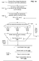
- FIG. 13 depicts method aspects for implementing such an approach to ray tracing.
- FIG. 13 depicts that intersection indication processing 1302 communicates with collection readiness processing 1303.
- Intersection indication processing 1302 handles returning indications of intersections of rays and acceleration elements, and can be implemented, for example, in packet unit 608. Exemplary aspects of such processing also were explained with respect to FIG. 9 , and include that rays indicated as having intersected an acceleration element are distributed among collections of ray identifiers.
- Collection readiness processing 1303 includes that status of the collections can be monitored 1304, such as by gathering statistics concerning memory usage, and/or fullness of the collections individually and/or in the aggregate.
- any such identified or otherwise selected collections can be evicted or flagged as ready for test, and in the example of FIG. 8 , can be stored in ready list 812.
- FIG. 14 depicts a aspects of a method that includes ray traversal, ray sorting, and preparation for shading.
- FIG. 14 depicts that rays can be traversed through an acceleration structure (e.g., that of FIG. 12 ).
- FIG. 14 also depicts that in one implementation, rays of collections(s) can be intersection tested by a bounding element (e.g., a leaf node) that can be considered as completing the traversal.
- a bounding element e.g., a leaf node
- Such an element can be a leaf node, or can be another node in the acceleration structure (e.g., a node bounding primitives associated with an object). In either case, the rays can be sorted based on a current possible closest detected intersection for that ray and the object containing that possible closest detected intersection.
- a sorting criteria can be determined.
- such sorting criteria includes using an identifier associated with each primitive.
- such sorting criteria can include that a common shader, or a portion of a shader code module, and more generally, common data to be accessed and/or code are to be used and/or executed in shading the intersections. The sorting criteria can then be used in sorting the intersections.
- a function 1432 of using a ray identifier to lookup a primitive intersected by the ray can also be employed, such that a datapath between ray intersection testing and sorting logic can be provided for ray identifiers, and a memory lookup function can be provided to obtain intersection information for identified rays, when required.
- the lookup can be made from ray definition data storage 211, which can be distributed among a plurality of intersection test areas (see e.g., FIG. 6 ).
- sorting (1407) of intersections (or possible intersections) into object-associated buffers can be made based on the intersected information then-available (actual and/or possible intersections), and can be implemented by a sorter.
- Buffers 1408, 1410, and 1412 are depicted as example buffers for receiving intersection information sorted by object; such buffers can be implemented as FIFOs, ring buffers, linked lists, and so on.
- Other implementations can sort rays into buffers based on association with a particular code segment, such as a shader.
- sorting 1407 of rays into buffers associated with a particular shader or a particular object can be implemented using ray tracing deferral aspects described above.
- primitives can each be given a unique number, some portion of which identifies a scene object to which the primitive belongs, and the sorting of the rays into various of the buffers can be based on a primitive identifier associated with the ray, or the scene object-identifying portion thereof.
- a buffer selection 1418 can control from which buffer ray intersection information is obtained for conducting shading operations.
- Buffer selection 1418 can operate by selecting a fuller or fullest buffer from among buffers 1408, 1410, and 1412.
- buffer selection 1418 can select any buffer having more than a minimum number of rays collected therein (collecting rays preferably refers to collecting identifiers for the rays, but also can include collecting definition data for the rays in the buffers).
- a ray result lookup function 1430 can be provided for implementations where buffers 1408-1412 store ray identifiers, but not all data that would be used to identify a particular intersection, such as a primitive identifier.
- rays can be collected by object, and shader code associated with that object can be loaded 1420, and stored, such as in cache 1419. Shaders further can load (1422) definition data for rays identified in the data read from the selected buffer(s). Vertex attribute data for the object(s) associated with rays from a selected buffer can be paged (1424) from memory. Further during execution shader code loaded for the object can sample texture and other data useful in shading of ray intersections.
- the collections maintained in buffers 1408, 1410, 1412 can be larger, and in some cases much larger than collections maintained with respect to nodes of the acceleration structure. For example, each buffer can hold 256, 512, 1024, 1096, 2048, or more or fewer ray intersection indications.
- Buffering approaches can include including buffer segments of a comparatively small size, such as 128 entries and linking them as needed for a larger buffer. Still further approaches can include having a plurality of buffer sizes, and selecting a buffer size based on a number of primitives composing a shape to be associated with the buffer. For example, a shape associated with 250k primitives can be associated with a smaller buffer than a 1M primitive shape. Buffer sizes can be created based on an analysis of the scene and the objects composing it. For example, if the scene has a distribution of many smaller objects, than more smaller buffers can be allocated; conversely, if there are fewer larger objects in the scene, then fewer larger buffers can be allocated.
- intersection testing resources can concurrently test 32, 64 or more rays for intersection with selections of primitives that can be related to, or part of, the same scene object. Any rays found to intersect from that concurrently testing can be outputted as a group, without buffering, such as buffering to await more rays intersecting the same object.
- buffering can be used to aggregate hundreds or even thousands of rays for outputting to shading.
- system implementations can include a software or hardware implemented function that allows a lookup of what triangle was intersected by a given ray.
- the buffers need not store the triangle identifier with the ray or ray identifier, and instead, a lookup can be conducted using the ray identifier when the ray is ready to be shaded.
- testing 1404 can be implemented by structure and systems according to the examples of FIGs. 2-5 .
- FIG. 15 depicts further examples of how ray collections can be grouped based on object intersection information, or at a more granular level based on portions of shader code being executed.
- FIG. 15 depicts intersection processing resources 202 that can comprise a plurality of execution cores (threads) 1510a-1510n, an intersection shading scheduler 1507, and a cache hierarchy 1515 that can comprise a plurality of cache memories.
- cache hierarchy 1515 can comprise a plurality of caches located on-chip, and/or within a module in which execution cores 1510a-1510n are located. Further memories 1517 can be accessed off-chip.
- Intersection processing resources 202 can execute shader code in execution cores 1510a-1510n, and in this particular example, shader instances 1520a and 1520b are depicted, which are differences instances of the same shader. Shader instance 1521 is also depicted as an instance of shader code for a different shader.
- Scheduler 1507 can create points of aggregation at which rays can be collected to defer their shading in favor of shading collections of other rays.
- Collection point 1522 depicts a logical view that shading scheduler 1507 can aggregate rays to await execution of the two depicted shader instances 1520a and 1520b (depicts an entrance point of such shader code). Thus, as rays are deferred, they are collection into a collection associated with collection point 1522. When the collected rays are to be shaded, data useful in their shading can be paged into cache hierarchy 1515 (as explained with respect to FIG. 14 ).
- FIG. 15 also depicts that shaders may comprise multiple sections of code, and may also branch and call other modules of code.
- code 1525 is depicted as code that was branched to during execution of shader instance 1520a, but not shader instance 1520b.
- Modules 1531 and 1532 are examples of modules, such as a diffuse lighting modules that can be called by shaders.
- a collection point can be provided by scheduler 1507 to collect rays of shader instances that have made calls to such modules.
- collection point 1530 represents collecting rays that have called module 1532.
- such calls can come from instances of different shader code (here, instance 1520b and instance 1521).
- instance 1520b and instance 1521 Once module 1532 has been executed for rays collected at collection point 1530, shaders continue in their normal shading path. For example, rays collected from module 1532 can return to execute code 1535, and call module 1536, after completion of module 1532.
- shader instance 1520a had two taken branches in which module 1531 is executed for some rays while module 1532 was executed for other rays.
- Collection point 1530 applied only to module 1532, such that for those intersections that took the module 1531 branch, they would execute code 1533, and ultimately converge to the same code path at module 1537, as would those intersections that took module 1532, executed code 1534 before converging at module 1537.
- FIG. 15 is only exemplary at scheduler 1507 can provide a variety of collection points, within shader modules, based on calls to provided modules, based on access to defined regions of memory that have been loaded with object data for certain objects or object portions, and so on.
- ray intersection processing can be collected at a start of diffuse lighting calculations, such that diffuse lighting calculations can proceed for a number of rays that intersected portions of the same object, and in other examples, rays that intersected portions of the same or different object, and whose shaders use a diffuse lighting call can be collected.
- each ray also can be associated with a default bin or buffer in which it is to be sorted, absent a detected intersection.
- the specified bin or buffer can be a bin or buffer that also is associated with one or more primitives, or objects, or particular code modules, such that some rays end up there by virtue of their respective default assignment, while others end up there as a result of detecting an intersection that causes that ray to be binned or buffered there. Therefore, although the prototypical example is sorting/buffering/binning based on detected intersections, examples also can provide functionality that allows each ray to specify a default. An API call allowing ray emission can be made to accept that default assignment.
- systems according to these examples can more broadly operate to allocate resources between driving intersection testing into further areas of a scene structure, and to produce a wider variety of rays and to starting new camera rays. Ultimately, it is expected to test all rays emitted by the shaders that execute, but an order of execution can have important effects on memory usage during rendering.
- computing resource(s) include a thread, a core, a processor, a group of processors, a virtual machine, a fixed function processing element, and the like.
- computing resource(s) include a thread, a core, a processor, a group of processors, a virtual machine, a fixed function processing element, and the like.
- computing resources can provide means for implementing these functions.
- other functions that may be used in implementing embodiments can be provided or implemented as a process, thread or task that can be localized to one computing resource or distributed among a plurality of computing resources ( e . g ., a plurality of threads distributed among a plurality of physical compute resources).
- computing resources being used for intersection test can also host other processes, such as shading processes that are used to shade intersections detected.
- shading processes that are used to shade intersections detected.
- a thread can be dedicated to shading while another thread can be dedicated to intersection processing.
- the described examples can be used in transforming a 3-D scene into a 2-D representation of it, as viewed from a defined vantage point.
- the 3-D scene can include data representations of physical objects.
- Other results of ray intersection testing can include object visibility determinations, which can be used in a variety of applications.
- Other transformations include transforming computer readable media into a different state by storing data determined according to the defined methods.
- Computing resources 1604-1607 may comprise any one or more of a plurality of processing cores, processors, that can each comprise fixed function and/or programmable elements.
- the computing resources 1604-1607 may also comprise different threads of computation on a multi-threaded processor, for example.
- Each of computing resource 1604-1607 may have read and write access to a respective L1 cache 1625a-1625n, that can be integrated with its computation resource or separate.
- a plurality of L2 caches, e . g ., L2 cache 1630 and L2 cache 1635, can be provided and can be shared among the computation resources or private.
- a shared L3 cache and/or a main working memory 1640 can be provided.
- ray data 1610 and shape data 1615 can be stored in L3/main memory 1640.
- the example system 1600 can execute one or more applications and the scene builder workflow, e . g ., application/builder 865.
- the computation resources can communicate with each other over a shared bus 1601, or using point to point connections, or through shared memory space in the L2 caches 1630 and 1635 or L3/main memory 1640.
- these systems and methods can be used in rendering representations of a 3-D scene for use in holographic imaging systems.
- a plurality of images of a given scene are to be rendered, each from a different perspective.
- each perspective can be considered to be an origin of rays to be intersection tested.
- the rays of each perspective can be collected together for intersection testing, such as collecting rays of different origins and their progeny together, without regard to their origins, but rather with respect to commonality of intersection testing and/or shading to be performed.
- Allowing collection of rays from a plurality of such origins allows systems and methods to provide for setup of the 3-D scene once, so that such scene setup is amortized over a large number of image renderings. Also, combining rays to be traced from different origins may allow for greater coherence and overall processor utilization. Thus, in the above examples, where collections of rays are formed, outputted, or otherwise handled according to the disclosures, these rays can be attributed to a plurality of camera positions. For example, rays of a given collection can be tested against child nodes of a parent node of a common acceleration structure.
- Another application of these disclosures comprises determining mappings between data elements of a first type, which can be defined during execution of a computer-implemented process to data elements of a second type, which comprise code modules that can use information provided in elements of the first type during execution of the process.
- an application comprises determining, based on characteristics of the potential inputs and characteristics of the code modules, which code module is to receive which input.
- code modules can generate further potential inputs, for which the determination is to be conducted again.
- a complete dataset to be processed is developed or otherwise evolved during execution of the application itself.
- some classes of processes may have an entirety of possible actions to be taken specified prior to initiating the process; for example, code modules that accept data elements used as inputs in the code modules can be specified prior to execution of a program or process that uses the code modules.
- code modules that accept data elements used as inputs in the code modules can be specified prior to execution of a program or process that uses the code modules.
- which actions are to be taken or code modules executed, in a more specific instance), and under what circumstances those actions are to be taken, may be indeterminate prior to initiation of the process or even at any given point during the execution of the process. Instead such information is determined during iterations of process execution.
- an entirety of the data set used during execution of a process may be indeterminate at commencement of the process.
- data elements can be used as input to code modules that may use parameters of these data elements as inputs, and can also instantiate new data elements as outputs of execution.
- data elements When data elements are instantiated, they are to be closed either by determining that they cause no further code executed, or an appropriate portion of code to be run for each of them is identified (and executed, depending on how the closure is defined).
- a preliminary setup for executing the process includes establishing an n-dimensional space in which code portions (e.g., code modules or portions of a module) can be inter-related or organized by associating the code portions with one or more points or locations in the n-dimensional spatial structure (such code portions also can be associated with defined regions in n-dimensional space, but preferably, they are associated with points, and the description uses this example, without limitation).
- code portions e.g., code modules or portions of a module
- code portions also can be associated with defined regions in n-dimensional space, but preferably, they are associated with points, and the description uses this example, without limitation.
- the n-dimensional space can be sub-divided by an acceleration structure comprising a plurality of elements, where each of the elements establishes a hypersurface (for convenience, called a surface - as in a 3-D structure) that bounds a respective selection of points associated with respective code portions.
- the acceleration structure is hierarchical, with child elements of parent elements (this example will be used below, for ease of description, but hierarchy in the acceleration structure is not required).
- parent acceleration elements bound supersets of the points bounded by their children, but do not necessarily bound the entirety of the surfaces of the child elements themselves.
- a plurality of data elements are defined (or obtained), for which processing may need to be conducted.
- a search in the n-dimensional space is to be conducted to determine one or more code modules that are to be run for closing processing of those data elements (and in some more general cases, whether any processing is to be done for a given element).
- the search is to be conducted based on criteria specified in the data element, which comprise one or more parameters whose permissible range of values define a path or region in the n-dimensional space.
- parameters can comprise an origin and direction specified in 3-D space, which define a line in 3-D space.
- parameters may define a 3-D object, such as a sphere.
- Hyperdimensional regions can be defined by regular or irregular bounds in the n-dimensional space.
- the region can be contiguous or non-contiguous, e.g., the region may comprise a union of a plurality of disjoint portions of n-dimensional space.
- a data element defines a spatial extent in the n-dimensional space, where n can be two or more; the spatial extent depends on the parameters and values of the parameters defined for a given data element ("spatial" is used here for increased understanding, and without limitation as to a number of dimensions in the operational space).
- the spatial extent for that data element is tested for intersection in the n-dimensional space with surfaces (hypersurfaces) defined by elements of the acceleration structure. As data elements are found to intersect surfaces of acceleration elements, those data elements are collected into collections associated with those acceleration elements.
- the searching can be done in a computation resource that comprises a plurality of test elements, such as threads, or dedicated test cells, that can test different data elements for intersection with a given surface (one example).
- This computation resource is limited in that it cannot concurrently perform all intersection testing that must be done, so this computation resource is to be scheduled.
- the allocation of the computation resource for the testing is based on scheduling collections of data elements for further testing, from a pool of collections. Rather than testing the data elements in an order in which they were defined or began testing, the data elements are tested based on membership in collections selected from the pool. Data elements can concurrently exist in multiple collections, and can be tested by virtue of membership in one collection, even while testing based on membership in a different collection is deferred.
- the deferral of some collections in favor of other collections provides for further collections to be traversed to join collections in the acceleration structure that have less full collections, such that, in general, data elements from fuller collections can be tested concurrently (heuristics for collection scheduling can include selecting collections having other characteristics in some circumstances).
- a collection of data elements would be tested next with children acceleration elements of the acceleration element to which the given collection of data elements was associated.
- the interesting result typically is a closest intersection from an origin of the ray being tested.
- a plurality of results can be returned, or a selected result, or an ordering of results.
- the results to be returned, and a format thereof can be specified by provision of a format to which a data element query can be formatted.
- Outputs from such testing can include indications of which data elements are to be used as inputs to (or triggers to execute) to which code portions.
- Such data elements also can be outputted as a collection, such that a number of the instances of the same or related code portions can be provided for different of the data elements.
- outputs of the code portions can include further data elements for which the described searching is to be conducted.
- scheduling of execution of the code portions themselves can include parallelizing the execution of the code portions for different of the data elements, such that common portions of the code can execute concurrently for different of the data elements.
- other data e.g, data other than what may be included within the data elements themselves
- used by the code portions can be retrieved and cached for use.
- systems according to the above examples can implement methods where data elements comprising a plurality of parameters whose values define a region in an n-dimensional space can be tested for intersection with hypersurfaces that bound points (or regions) in space which are associated with modules of code for execution.
- the data elements found to intersect such hypersurfaces can carry data which can be used as input to one or more of the code modules bounded by an intersected surface.
- system can perform further testing to establish a nearness or intersection to a specified degree of precision between the region defined by a given data element and a point associated with a given code module.
- Testing of a plurality of data elements preferably is performed concurrently in systems by deferring further testing of individual data elements to accumulate a number of data elements found to intersect a given hypersurface and scheduling other accumulated data elements for testing on provided system resources.
- Computer code and associated data can be provided for implementing methods and other aspects described herein.
- the computer code can comprise computer executable instructions that may be, for example, binaries, intermediate format instructions such as assembly language, firmware, or source code.
- the code may configure or otherwise cause to be configured a general purpose computer, a special purpose computer, or a special purpose processing device to perform a certain function or group of functions.
- Any such code can be stored in computer readable media, such as solid-state drives, hard drives, CD-ROMs and other optical storage means, transiently in volatile memories, such as DRAM, or less transiently in SRAM.
- a variety of implementations can be provided which can include interoperative hardware, firmware and/or software that can also be embodied in any of a variety of form factors and devices, including laptops, smart phones, small form factor personal computers, personal digital assistants, and so on. Functionality described herein also can be embodied in peripherals or add-in cards. Such functionality also can be implemented on a circuit board among different chips or different processes executing in a single device, by way of further example.
- machines for according to these examples can comprise intersection testing resources including particular fixed-purpose testing cells, and/or general purpose computers configured with computer readable instructions from a computer readable medium to perform the particular intersection tests described and interpret the results of the tests.
- Further machine components include communication links for providing the acceleration structures to the testing resources and to receive the results of the testing.
- the machines for intersection testing can be a component of a larger system including other input and output devices, such as a drive for reading scene description data, and a display or a computer readable medium for outputting rendered scenes.
- the computer readable medium can be a DVD and each scene may be a frame of a motion picture.
- the 3-D scene being rendered can represent an abstraction or a model of a real-world scene and the rays being tested also can represent light energy being emitted from lights located in the scene.
- the usage of the camera also can represent a vantage point of an observer for the scene.
- the output of intersection testing results in determining how light affects the scene and ultimately affects output that can be consumed by other applications, can be stored in computer readable media, and can be displayed to a user.
Abstract
Description
- This application claims priority to
U.S. provisional patent application no. 61/095,890, filed on September 10, 2008 U.S. provisional application nos. 61/229,258, filed on July 28, 2009 61/229,705, filed on July 29, 2009 U.S. Pat. App. No. 12/555,766, filed on September 8, 2009 - The following relates to rendering, using ray tracing, two-dimensional representations of three-dimensional scenes composed of shapes, and more particularly to systems, methods, and means for intersection testing of rays in 3-D scenes.
- Rendering photo-realistic 2-D images from 3-D scene descriptions with ray tracing is well-known in the computer graphics arts. Ray tracing usually involves obtaining a scene description composed of geometric shapes, which describe surfaces of structures in the scene, and can be called primitives. A common primitive shape is a triangle.
- Virtual rays of light are traced into the scene from a view point ("a camera"); each ray is issued to travel through a respective pixel of the 2-D representation, on which that ray can have an effect. The rays are tested for intersection with scene primitives to identify a first intersected primitive for each ray, if any.
- After identifying an intersection for a given ray, a shader associated with that primitive determines what happens next. For example, if the primitive is part of a mirror, then a reflection ray is issued to determine whether light is hitting the intersected point from a luminaire, or in more complicated situations, subsurface reflection, and scattering can be modeled, which may cause issuance of different rays to be intersected tested. By further example, if a surface of an object were rough, not smooth, then a shader for that object may issue rays to model a diffuse reflection on that surface. As such, finding an intersection between a ray and a primitive is a first step in determining whether and what kind of light energy may reach a pixel by virtue of a given ray, since what light is hitting that primitive still needs to be determined.
- Thus, most conventional algorithms build a tree of rays in flight when ray tracing a scene, where the tree continues along each branch until it leaves the scene or hits a luminaire that does not issue new rays. Then, for those branches that hit light emissive objects, the branches are rolled up through the primitive intersections, determining along the way what effect each primitive intersection has on the light that hits it. Finally, a color and intensity of light for the originally issued camera ray can be determined and stored in the buffer.
- Ray tracing can be naively parallelized by providing many processing resources that operate on different portions of pixels of a 2-D scene to be rendered. However, simply providing more computation capability does not necessarily allow a suitable scaling of ray tracing speed and efficiency. One reason for this is that such parallelization does not account for how data composing the scene, or an acceleration structure that increases tracing efficiency can be accessed in an efficient manner. A variety of improvements to ray tracing architectures remain to be provided.
- In one aspect a ray tracing system comprises an input for receiving information for rays that have been found to intersect a primitive composing a 3-D scene being ray traced. The system also comprises a plurality of buffers. A sorter is coupled to the input and to the plurality of buffers. The sorter is configured for dividing the received information among the plurality of buffers by grouping together, in respective buffers, information for rays that are expected to be shaded using one or more of common shader code and common shader data. The system also comprise an output for outputting contents of a selected buffer to a computation resource to be configured for shading intersections for the rays for which information is stored in the selected buffer. In one embodiment, the information for each ray comprises an identifier for that ray. In addition to ray identification information, identification information for one or more primitives that may have been intersected can be stored in association with identification information for the potentially-intersecting ray. Other information characterizing a closest detected intersection also can be stored in the buffers, or retrieved from a memory upon buffer selection. The output can provide the information from the buffer as a stream, such as a stream of ray identifiers and other information associated with those ray identifiers, as applicable.
- In some embodiments, primitives potentially intersected by a given ray can have respective identifiers. These identifiers can be used to determine an object of which those primitives are a part. In turn, commonality of object can be used to infer commonality of one or more of shader code and shader data to be used during shading of intersections involving different rays. In some embodiments, objects can be associated with discrete shader code modules, and in some embodiments, primitives can each be associated with shader code modules, or portions thereof.
- Ray tracing systems according to the above embodiments and aspects also can comprise the computation resource to be configured for shading ray intersections, which can be configured to arrange for storage of retrieved shading data in a cache for local access during shading of the indicated intersections for the rays from the selected buffer. The computation resource to be configured for shading intersections also can be configured for performing final intersection testing of a plurality of identified primitives, which may have been intersected by a given ray to identify an actual intersection of the given ray to be shaded. Such functionality also can be implemented by a computation resource intermediating between the intersecting testing and the shading. Any such ray tracing systems can output ray information by streaming ray identifiers from the selected buffer to the computation resource for shading their respective intersections.
- Other aspects of exemplary ray tracing systems can comprise an intersection testing resource with an intersection testing input for receiving identifiers for rays that are to begin intersection testing in the intersection testing resource. Such ray identifiers can be received from a plurality of shader code modules, and would be outputted in blocks to begin intersection testing, and preferably concurrent testing, of rays identified by those ray identifiers. Such concurrent testing can be performed by systems that comprise an intersection testing resource that comprises a plurality of test cells, and is configured for splitting blocks of ray identifiers among the test cells for concurrent testing of the identified rays. The input is configured for gathering identifiers of rays outputted from the plurality of the test cells as the ray information.
- Other aspects comprise methods of ray tracing. One example is a method that comprises providing data defining objects composing a 3-D scene, where the data comprising definition data for primitives that compose the objects. The method also comprises defining a plurality of rays to be processed, the processing for each ray comprising identifying a respective closest intersection, if any, with the primitives and shading such an intersection by executing one or more code modules. The method also comprise outputting groupings of information for rays for which a closest intersection has been identified, where the groupings were formed based on one or more of expected commonality of code modules and expected commonality of data to be used during shading of intersections for the identified rays. In some such methods, the outputting comprises storing the ray information for the groupings in an output-pending buffer. The ray information can comprise ray identifiers, identifiers for one or more primitives that may be have been intersected by each identified ray, and in some embodiments, only a primitive that was first and actually intersected by each ray.
- In such methods, the identifying a respective closest intersection can comprise producing associations between identifiers for intersected primitives and identifiers for rays that have intersected those primitives. The primitive identifiers can be used to determine expected commonality of code modules to be executed for shading intersections involving those primitives.
- Such exemplary methods also can further comprise storing definition data for the plurality of rays in a distributed memory, and performing the identifying of respective closest intersections for the rays of the plurality in a plurality of test cells. Each test cell can have an allocated port to the distributed memory. The distributed memory also can store data identifying a current closest detected intersection for each of the rays..
- In systems and corresponding methods, a controller can make collections of rays, at least some of the collections associated with respective scene objects composing the 3-D scene. The collections can be formed both for intersection testing and shading. In some example,s the collections formed for shading can be limited only to rays for which an actual intersection has been identified. In other examples, collections can be formed from leaf nodes of an acceleration structure, where those leaf nodes have been defined to bound primitives of a common scene object (such leaf nodes also can be selected or defined based on a determined commonality of one or more of shader code and shader data).
- Other aspects comprise a method for providing a ray tracing system, which comprises providing an intersection testing resource operable for concurrent intersection testing of a plurality of rays in a 3-D scene, which results in identification of detected valid intersections for at least some of the plurality of rays. The method also comprises providing an intersection shading resource for configuration to run shading code for shading detected valid ray intersections, and providing for communication between the intersection testing resource and the shading resource. The communication can be implemented by outputting one or more groupings of information for the detected intersections, the groupings determined based on an expectation that each intersection of each group will be shaded with one or more of common shading code and common shading data. The groupings can be formed by sorting rays based on identification information for respective primitives they intersected. Such methods also cancomprise providing for buffering of new ray data from the shading resource to the intersection testing resource. The buffering of new ray data can comprise collecting new ray data from a plurality of shader code modules for initiation of concurrent intersection testing of those new rays. Such methods also can comprise providing functionality, such as a control module function, for scheduling one or more threads to function as the shading resource for executing the common shading code.
- The above systems and methods can be implemented using computer executable code obtained from computer readable media. Such code can be provided in functional modules for implementing system components and other aspects described above, and can be embodied in hardware including application specific circuits, programmable gate arrays, and other custom or semi-custom logic, in addition to configuring general purpose processors.
- Another example system comprises a plurality of intersection testers, each operable for testing a ray for intersection with a shape defined by shape data provided to it. The ray to be tested by each of the intersection testers is defined by data locally accessible by that intersection tester. The system comprises a controller for collecting, from the intersection testers, associations between elements of an acceleration structure bounding primitives composing the 3-D scene and identifiers for rays that have been determined to intersect each element.
- The system also comprises an interface between the controller and the plurality of intersection testers. The interface can receive a group of identifiers for rays to be tested, and disperse the ray identifiers among the intersections testers, based on which of the intersection testers can locally access definition data for each ray. Such an interface can abstract the plurality of testers from the controller, such that the testers do not need to be aware of the source or nature of the data they test. Likewise, results from the test cells are abstracted by the interface, such that the controller does not need to poll or otherwise query particular test cells for results of particular tests.
- In addition, such a system can comprise a computing resource for shading intersections between rays and primitives composing the 3-D scene. The shading can result in new rays to be intersection tested. The system also can comprise a second interface abstracting the controller and the plurality of testers from the shading computing resource. The second interface is operable for receiving definition data for the new rays, and assigning respective identifiers for the new rays by which each of the new rays is to be identified during tracing.
- In some embodiments, such the test cells of such a system can be organized into subsets to form a plurality of test regions. Each test region can comprise a private memory for storing a respective subset of definition data for rays being intersection tested with objects of a 3-D scene. The first interface can be operable to receive a packet comprising a plurality of ray identifiers from the controller. Each ray identifier is mappable to one of the rays for which definition data is stored in the private memories of the test regions, and used in determining which test region includes definition data for each ray identified in the packet.
- Another aspect comprises a system for querying a database of information, with an imposed hierarchical acceleration structure that has elements grouping subsets of the information. The system comprises an input buffer, and a memory for storing data defining testing requests remaining to be satisfied from the database. The system also comprises testing logic for performing concurrent testing of discrete queries (i.e., queries that when submitted had no known relationship to each other) whether elements of the acceleration structure meet criteria defined by the query. The discrete queries are collected into collections based on outputs of the testing. The testing resources are scheduled for further querying by scheduling collections for test, such that discrete queries can be satisfied out of an order submitted. One result of such queries is identification of a code module to be executed based on one or more parameters defined in the query. Results also can include identifying other data to be used during execution of the code module. In some cases, the code module execution can result in more queries to the database.
- Still other aspects comprise a method of tracing rays in a 3-D scene. The method comprises dispersing rays being traced in the scene among a plurality of elements of a hierarchical acceleration structure. Each element bounds a respective sub-portion of the 3-D scene, forming respective collections of rays that have been determined to intersect each of the elements. The method also comprises selecting rays for further dispersal based on selecting collections of which they are members. The selecting accounts for both respective numbers of rays in the collections and respective positions of the elements in the hierarchical acceleration structure to which the collections are associated.
- Systems and methods implemented in the above systems can operate through the described interfaces by maintaining a credit count indicative of numbers of rays (and more broadly, queries) sent to the traversal unit and numbers of rays for which results are returned from the traversal unit. The credit count can be used in determining when to send new rays (queries) to the traversal unit.
- Other method aspects that can be used in such systems, or in other systems comprise, in a software-based driver, allocating a portion of a memory for storing ray definition information. A size of the memory portion to be allocated based on a total number of rays for which intersection testing status is to be maintainable. The method also comprises accepting commands from an intersection testing controller that maintains status for rays that are stored in the allocated memory portion to provide more rays for storage in the memory portion from a larger pool of rays that await intersection testing.
- Still other component methods that can be used in or with such systems or other systems comprises a method of setting up an acceleration structure for intersection testing. The method comprises representing definition data of an element of an acceleration structure with using a first number of bits responsive to the element being greater than a threshold in size. The method also comprises using a second number of bits, larger than the first, for representing the definition data responsive to the element being less than or equal to the threshold in size. In an intersection tester, the testing can proceed with the higher precision format if the element is smaller than a threshold in size; and with the ray using a lower precision format if the element is greater than or equal to the threshold in size.
-
-
FIG. 1 depicts a simplistic toy scene with a camera emitting rays that are intersection tested, and such intersections cause shaders to execute, emitting further rays for intersection testing; -
FIG. 2 depicts an example system architecture in which an intersection testing resource, a computation resource for executing shaders, and examples of their interconnection are illustrated; -
FIG. 3 depicts an example intersection testing architecture and control logic for managing usage of the components thereof; -
FIG. 4 depicts an example intersection testing architecture illustrating further details of how aspects of the above architectures can be implemented; -
FIG. 5 depicts an example of how intersection processing (shading) and intersection testing (tracing) can be abstracted for ray tracing using ray identifiers meaningful within the scope of shading, and carried through ray tracing; -
FIG. 6 depicts further details of an example architecture for providing ray tracing functionality in a system; -
FIG. 7 depicts an example organization of a packet that can be sent from a packet unit according toFIG. 6 , and used by an arbiter to trigger intersection testing of rays that the packet identifies; -
FIG. 8 depicts aspects of a tester that can be used in ray intersection testing, and which can be abstracted from its control by the arbiter ofFIG. 6 ; -
FIG. 9 depicts an example ray intersection testing results processing flow that can be implemented in the packet unit depicted inFIG. 6 ; -
FIGs. 10A and 10B depict aspects of an example where packets contain a surplus of ray identifiers for available ray intersection tester resources; -
FIG. 11 depicts an example intersection tester architecture that can be used in disclosed examples; -
FIG. 12 depicts an acceleration structure for describing further aspects that can be implemented in ray tracing architectures; -
FIG. 13 depicts aspects of how collections maintained by packet unit can be selected to be tested, under different conditions detectable by the packet unit; -
FIG. 14 depicts details of aspects relating to collecting intersecting rays by shader, or by intersected object, which is a component implementable in ray tracing architectures; -
FIG. 15 depicts data flow aspects relating to collecting and shading of collected rays based on intersected object and more granular shading code components; and -
FIG. 16 depicts components of a system that can be used in implementing ray tracing aspects disclosed with respect to previous figures. - The following description is presented to enable a person of ordinary skill in the art to make and use various aspects of the inventions. Descriptions of specific techniques, implementations and applications are provided only as examples. Various modifications to the examples described herein may be apparent to those skilled in the art, and the general principles defined herein may be applied to other examples and applications without departing from the scope of the invention.
- For clarity in description, data for a certain type of object, e.g., a primitive (e.g., coordinates for three vertices of a triangle) usually is described simply as the object itself, rather than referring to the data for the object. For example, when referring to "a ray", it is to be understood that data representative of that ray is referenced, as well as the concept of the ray in the scene.
-
FIG.1 illustrates a simplified scene setup, in which a 2-D plane 175 is disposed between acamera 105 and ascene 150, comprisingobjects camera ray 130 is emitted from camera 105 (such using program code descriptive of behaviors of the camera). It is determined through intersection testing thatray 130 intersectsobject 110. A ray 131 is emitted by a shader (e.g., program code and data describing behavior for an object or surface) associated withobject 110. For example, object 110 may have a mirrored surface, and as such the shader for it would generate ray 131 to test reflection at an angle thatray 130 was incident onobject 110. It then is determined that ray 131 hits object 115. For simplicity, a shader associated withobject 115 is shown to have similar behavior to that of the shader forobject 110, emitting a ray 132 to test whether light is incident onobject 115 at an angle that could have traveled on the path of ray 131. Ray 132 is determined to intersect light 120. - The example of
FIG.1 was necessarily grossly simplified. Many factors adding computational cost to a more realistic ray tracing scene include that the resolution of the 2-D representation to be rendered can be high, such as a full HD resolution of 1920x1080 pixels (over 2 million pixels). Each pixel of the scene can have many rays emitted from the camera that are associated with it. Thus, rendering such a scene can involve initially testing many millions of camera rays alone, followed by much higher numbers of rays that are emitted by shaders identified based on object intersections with camera rays, and in turn rays subsequently emitted by shaders. - Shaders can involve substantial computation and emission of further rays that test various conditions. For example, shaders can perform diffuse lighting tests, such as Monte Carlo diffuse lighting, which involves emission of a number of rays to test ambient lighting conditions. Shaders may emit rays to test whether an intersection point is shadowed by another object for known light sources in the scene. Shaders also can model complex materials characteristics, such as subsurface scattering for skin, reflection, refraction, and so on. Each of these functions can involve emission of rays that need to be intersection tested in the scene. Thus, rendering a full HD high resolution 2-D representation of a complex scene can involve intersection testing of hundreds of millions or more rays.
- Thus, for purposes herein, this example shows that a ray is tested for intersection in a scene. If it is found to intersect an object (e.g., a primitive), then a shader associated with that object can be identified and executed. That shader can in turn emit more rays to be intersection tested. The number and type of rays that shader emits typically depends both on characteristics of the intersecting ray and also on the effects that the shader is implementing.
- With so many rays needing intersection testing, not all rays can be intersection tested concurrently. Also, considering the rendering of a scene progressing from start to finish, at any given time, not all rays that need to be traced to complete the rendering have been defined, since scene rendering itself determines what rays will be tested.
-
FIG. 2 illustrates anexample system 200 for use in rendering a scene with ray tracing techniques.System 200 comprises amain memory 205, in which is storeddata 206 for intersection shading (e.g., shader code, textures, procedural geometry, and so on), primitives and acceleration shape elements (e.g., triangles, triangle strips, vertexes, bounding spheres, axis aligned bounding box or k-d tree definitions, and so on), and a master copy ofdata 208 defining the rays currently being tested for intersection in the scene. Themain memory 205 communicates with anintersection processing resource 202, in which shaders for identified ray/primitive intersections can be run. The communication betweenmemory 205 andintersection processing resource 202 is shown to include link 221 for providingintersection shading data 206 frommemory 205, and link 222 for providing primitive data frommemory 205. - The
intersection processing resource 202 operates to shade intersections identified by anintersection testing resource 210.Intersection testing resource 210 is directed to test rays by a controller 203. Controller 203 provides indications of rays to be tested tointersection testing resource 210 via alink 225; preferably controller 203 indicates rays to be tested by providing an identifier, which can be related to a memory location storing data defining that ray resident incache 211. In that preferred situation, definition data for the rays to be tested is obtained/received vialink 228 fromray definition cache 211. Intermediate testing results of a current closest detected primitive intersection can be stored with ray definition data in cache 211 (i.e., in some implementations, rays can intersect primitives, but if the rays are not tested in an order that the ray traverses the scene, then a farther intersection can be detected prior to a real, closest intersection, which is generally the only intersection of interest). - Closest possible detected intersections (if any) are indicated via a
link 224 to controller 203 (e.g., if a ray did not intersect any scene object that that ray may or may not be indicated through link 224).Intersection testing resource 210 receives primitive and acceleration shape data frommemory 205 throughlink 220. - Controller 203 arranges for processing of these possible closest indicated intersections in
intersection processing resources 202. Controller 203 receives data defining rays to be intersection tested that have been created by the shaders executing onresources 202. InFIG. 2 , link 226 is depicted for receiving such new ray data, while link 227 is depicted for providing information to instantiate shading of a particular intersection that was provided fromlink 224. Link 227 can comprise providing, or fetching code and data defining a shader, or otherwise directing intersection processing resources to perform such fetching frommemory 205. - Controller 203 also manages the master copy of
ray definition data 208 stored inmemory 205, and can store data defining new rays inmemory 205 vialink 223. Data stored inmemory 205 defining rays that have completed intersection testing are replaced by data defining new rays instantiated by the shaders. - The
intersection testing resources 210 and theintersection processing resources 202 can be implemented on aprocessing platform 201 and can comprise threads of processing on a multithreaded processor, or threads executing on separate cores of a multiple core processor, or physically separate processors, each potentially with multiple cores. Each thread can execute instructions from computer executable code obtained frommemory 205 or from another source. Similarly,memory 205 may be implemented as dynamic RAM accessible through a memory controller (not separately depicted) byprocessor 201.Cache 211 may be implemented in various levels, such as a private or semi-private L1 cache owned by one or more cores in a multiple core processor, L2 caches and L3 that may be shared among cores and/or among processors. Preferably, ray definition data stored incache 211 is protected from being overwritten by normal cache management algorithms, such as Least Recently Used, and the like. Instead, it is preferred that controller 203 manage the ray definition data stored incache 211, as a subset of the raydefinition data master 208. Such ray definition data incache 211 can be updated frommaster 208 vialink 229. - The links 220-229 illustrated may be implemented based on the implementation of the
cache 211,memory 205, and theintersection testing 210 andprocessing 210 resources. - Generally,
intersection testing resource 210 performs more fixed-function types of computation, in that it tests rays for intersection against shapes, usually either a primitive shape or an acceleration shape element, which bounds a selection of primitives defining the scene. By contrast, the types of computation to be performed during shading (on the intersection processing resource 202) is more general, in that shaders can perform a variety of computation, access, manipulate and create various data, and so on. Therefore, in some circumstances,intersection testing resources 210 can be implemented beneficially with more fixed-function processing, whileresources 202 can often be implemented beneficially on a more general purpose computing platform. Therefore, in some circumstances,intersection testing resources 210 can be provided as an acceleration function, add-in card, co-processor, or the like that either is fixed-function or can be programmed with the expectation that the programming will not change often during the rendering of a scene. - Implementations according to this disclosure need not have all characteristics shown in
example system 200. For example, insystem 200, rays are indicated for intersection testing by providing ray identifiers, separate from data defining the rays tointersection testing resource 210, which is optional. By further example, various links where illustrated, but depending on the implementation, not all such links may be necessary or desired. Instead,FIG. 2 depicts a system wherein computation resources can be provided for intersection testing, and they therefore produce indications of detected intersections. These intersection testing resources can operate concurrently with computation resources that are executing shaders for detected intersections. The shaders emit new rays for intersection testing, which are taken up for testing by the intersection testing resources. -
FIG. 3 includes a block diagram of an example of anintersection testing resource 210 that includes a plurality oftest cells 310a-310n and 340a-340n. Acceleration structure elements are illustrated as being sourced from storage 207 (elements of an acceleration structure can be defined by definition data contained in a memory that also contains data defining primitives of the scene. -
ITU 303 also comprisescollection management logic 303 and collection buffer 361. Collection buffer 361 andray data 211 can be stored in amemory 340 that can receive ray data from memory 139 (for example). Collection buffer 361 maintains ray references associated with GAD elements.Collection management 303 maintains those collections based on intersection information from test cells.Collection management 303 also can initiate the fetching of primitives and GAD elements frommemory 207 for testing ray collections. -
ITU 303 returns indications of identified intersections, which can be buffered inoutput buffer 375 for ultimate provision via results interface 225 tointersection processing 202. Indications may comprise information sufficient to identify a ray and a shape, such as a primitive, which the ray was determined, within a given degree of precision, to intersect. The degree of precision can include that a given bounding element bounding one or more primitives was found to be intersected by one or more rays, but each primitive has not yet been finally intersection tested with such rays. -
ITU 303 can be viewed as a function or a utility that can be called through a control process or driver that providesITU 303 with rays and geometric shapes against which the rays would be tested for intersection. For example,ITU 303 can be fed information through a driver, which can be considered in one aspect to be a process that interfacesITU 303 with other rendering processes, such as shading, and initial ray generation functions. From the perspective ofITU 303,ITU 303 need not be aware of the origin of the information provided to it, as it can perform intersection testing using the rays, GAD, and primitives (or more generally, scene objects) provided to it, or obtained by it based on other information provided to it. - As described above,
ITU 303 may control how, when, and what data is provided to it, such thatITU 303 is not passive, and may for example, fetch ray or geometry data, or acceleration data as required for intersection testing. For example,ITU 303 may be provided with a large number of rays for intersection testing, along with information sufficient to identify a scene in which the rays are to be tested. For example,ITU 303 may be provided more than ten thousand rays (10,000) rays for intersection testing at given time and as testing for those rays complete, new rays (generated by intersection processing 202) may be provided to keep the number of rays being processed in theITU 303 at about the initial number, as described below.ITU 303 may thereafter control (in logic 303) temporary storage of the rays during processing (in ray collection buffer 361 (seeFIG. 3 )) and may also initiate fetching of primitives and elements of GAD as needed during the processing. - As described above, GAD elements and primitives are transient in
ITU 303 compared to rays, as ray identifiers are maintained in buffer 361 and organized with respect to GAD elements, and data defining rays (ray data 211) is also maintained for use bytest cells 310a-310n and 340a-340n. Each of buffer 361 andray data 211 can be maintained inmemory 340, which may be physically implemented in a variety of ways, such as one or more banks of SRAM caches. - As introduced above,
logic 303 tracks status for ray collections stored inmemory 340, and determines which collections are ready for processing. As shown inFIG. 3 ,logic 303 is communicatively coupled tomemory 340, and can initiate delivery of rays for testing to each of the connected test cells. - In examples where a particular GAD element may bound both other GAD elements and primitives,
ITU 303 can have datapath for providing both GAD elements and primitives to each test cell, as well as rays, so thatlogic 303 can arrange for testing rays of collections among the testing resources. In such examples, because of the typical difference in shape between GAD elements and primitives (spheres versus triangles, for example), an indication to switch test logic or load an intersection test algorithm optimized for the shape being tested may be provided fromlogic 303. -
Logic 303 may directly or indirectly cause provision of information to testcells 310a-310n andtest cells 340a-340n. In indirect situations,logic 303 can provide information to each test cell so that each test cell may initiate fetching of ray data for test frommemory 340. Althoughlogic 303 is illustrated separately frommemory 340, for simplicity of description,logic 303 may be implemented within circuitry ofmemory 340, as management functionality performed bylogic 303 largely relates to data stored inmemory 340. - An ability to increase parallelization of access to
memory 340 by intersection test resources is an advantage of some aspects described herein. As such, increasing a number of access ports tomemory 340, preferably up to at least one per test cell is advantageous. Example organizations related to such parallelization are further described below. - Also,
ITU 303 can operate asynchronously with respect to units that provide input data to it, or receive outputs from it. Here, "asynchronous" can include that the ITU may receive and begin intersection testing of additional rays while intersection testing continues for previously received rays. Also, "asynchronous" may include that rays do not need to complete intersection testing in an order thatITU 303 received them. Asynchronous also includes that intersection testing resources inITU 303 are available for assignment or scheduling of intersection testing without regard to position of a ray within a 3-D scene, or a scheduling grid superimposed on the scene, or to test only rays having an intergenerational relationship, such as parent rays and children rays spawned from a small number of parent rays, or only rays of a specific generation - e.g., camera rays or secondary rays. -
Output buffer 375 can receive indications of identified intersections of primitives and rays which possibly intersected the primitive. In an example, the indications include an identification for a primitive paired with an information sufficient to identify a ray that intersected the primitive. Identification information for a ray may include a reference, such as an index, which identifies a particular ray in a list of rays. For example, the list may be maintained by driver running on a host, and the list may be maintained inmemory 205. Preferably,memory 205 also includes ray definition data for all the rays inmemory 340. However, the ray identification information may also include information, such as the ray's origin and direction, sufficient to reconstruct the ray, ifmemory 205 does not contain such information. -
FIG. 4 depicts aspects of an example architecture to which systems can be designed and organized herein. The architecture depicted comprises a plurality of intersection testing resources ("intersection testers") 405a-405n each coupled with arespective cache 465a-465n, in which is stored respectiveray definition data 466a-466n.Intersection testers 405a-405n receive scene objects to be tested for intersection throughdata lines 460, which can be fed through a memory access initiated by acollection manager 475. The shapes can be stored in a memory (e.g., a queue or a buffer) 440 to be made available tointersection testers 405a-405n. -
Intersection testers 405a-405n thus have local access to ray definition data in respective memories, and are directed to obtain and use portions of such ray definition data by receiving ray identifiers fromrespective input buffers 421a-421n.Input buffers 421a-421n can be provided in or otherwise serviced bydistribution logic 480 that implements decision points 413-415, in which a determination is made concerning whether a ray identifier provided fromcollection management 475 should be added to any ofinput buffers 421a-421n. - Each
intersection tester 405a-405n produces results that can be provided to collection management 475 (as illustrated throughresults channels 450a-450n). In some examples, such results are processed by collection management when the results are for intersections between rays and elements of an acceleration structure (i.e., GAD elements), while if the results are for intersections between primitives and rays, then those results can be outputted from or forwarded bycollection management 475.Collection management 475 maintains assocations between the ray IDs and the respective GAD element bounding objects to be tested next (and for which data is provided inbuffer 440 accessible tointersection testers 405a-405n. - In some examples,
buffer 440 is filled by DMA transactions initiated bycollection management 475 from a main memory (e.g., memory 205). For example, in a case of a hierarchical acceleration structure,buffer 440 can be made to store shapes that are children of a parent acceleration element, against which a collection of rays has been accumulated. Highest throughput is achieved when rays of a given collection are equally distributed amongcaches 466a-466n. - When multiple rays of a given collection are in one cache, then the other intersection testers can stall, or they can test rays from a next collection. Other aspects to note are that more than one ray ID for a given ray collection can be stored in any of
queues - Where multiple rays for a given collection are tested in one of the intersection testers (e.g.,
intersection tester 405b), the remainder of results for that collection can wait for all results of a collection to be assembled, or the "straggler" result can be propagated as available, and while other tester is performed by the testers. In some implementations, a maximum number of out of order tests can be accommodated (or otherwise designed for) before collection testing synchronization is again required, as described below. - In sum,
FIG. 4 illustrates a system organization allowing a packet of ray identifiers associated with one or more shapes to be distributed into queues for a plurality of testing resources, that each store a subset of ray data. Each test resource fetches ray data identified by each ray identifier against a shape loaded to the test resource. Preferably, the shapes can be streamed sequentially through all the test resources concurrently. The shapes can be identified as a sequence of children starting at an address in a main memory. Thus,FIG. 4 illustrates a system organization where a shape generally is tested concurrently against multiple rays. -
FIG. 5 depicts an alternate perspective on the architectural aspects depicted inFIGs. 2-4 , in conjunction with other functionality. One high-level aspect ofFIG. 5 is thatintersection processing 202 may communicate with intersection testing 210 through an abstraction layer 501. In some instances, of abstraction layer 501, shaders executing for intersection processing can instantiate new rays to be intersection tested. Such new rays can be identified by identifiers meaningful within the context of the processing resources executing the shaders. For convenience, those identifiers are called "software identifiers" or "SW identifiers". These SW identifiers can be provided with definition data for rays to be tested to a SW to HW ID mapper 515, which produces a respective identifier for each of those rays that can be used to identify such rays during their intersection testing. The SW identifiers for the rays can be stored with the ray definition data, and when intersection results for a given ray are to be reported, the SW identifier for that ray can be reported, along with intersection information. The SW identifier can be identified for a particular HW identifier using a HW ID toSW ID mapper 520. In other examples the SW ID can be stored with ray definition data inRAM 211, and in other examples, the HW ID can be a subset of bits of the SW ID, or can be based on an algorithmic transformation of the SW ID. - However, in the context of systems according to an architecture like that of
FIG. 4 , it is preferred that the HW ray ID be selectable so that intersection testing resources can have flexibility in determining where to store ray definition data for a particular ray. This determination can be made to effect load balancing among separate memories storing ray definition data. Independent ray identifier strategies according to this example allow ray identifiers to be sized appropriately for different purposes. For example, a master ray memory may be maintained, and subsets of those rays may be actively intersection tested to completion inintersection testing 210. Thus, a number of rays in the master memory can be many times larger than a number of rays actively being tested, making identifiers to uniquely identify each ray in the master memory longer. - This ray identifier approach also provides an example architectural choice that accepts a larger total memory footprint for storing a given number of rays, in order to gain a benefit that total data movement to repetitively test a given ray for intersection is comparatively less.
- Returning to
FIG. 5 , geometry andacceleration shape data 207 can be provided to both intersection processing (e.g. shading) and intersection testing (i.e., acceleration structure traversal and/or primitive intersection testing). - Results returned from intersection testing 210 to
intersection processing 202 can comprise indications of detected intersections of rays against one or more of primitives and acceleration elements. In some implementations, rays can be collected or otherwise buffered at an output of intersection testing (e.g., output buffer 375). Buffering can be implemented in a variety of ways and can include that rays are sorted based on a variety of common attributes. As previously explained, rays can be collected into collections based on acceleration element, and it also was disclosed that acceleration elements can be made to bound a particular scene object. In some examples then, the collection of rays can be based on scene object. In some implementations, this collection strategy also can allow collection of rays to be executed against a common shader. - As shown with respect to
output buffer 375, buffering of rays can be made to allow collections of rays to be executed against common shading code. Further, data elements to be used can be increased in locality by collecting rays inoutput buffer 375 so that vertex attributedata 511,texture data 512, and/oruniform data 513 can be made available for a given object to be used for shading a number of rays in a compact timeframe. In some respects,cache 514 can be loaded with these kinds of data after a number of rays are collected that intersect an object that uses such data. For example, a larger set of vertex attributes can be fetched and stored incache 514 for an object intersected by a number of rays. -
FIG. 6 depicts further aspects of an implementation of an intersection tester (e.g., intersection testing 210). As described with respect toFIG. 4 , a number ofintersection testers 405a-405n can be provided. Each of the testers can interface with arespective buffer 421a-421n. The buffers can contain ray identifiers and information about objects to be intersection tested with rays identified by the ray identifiers. The ray identifiers can be provided from aready packet list 612 that is controlled (via control 631) from apacket unit 608.Ready packet list 612 can contain a list of ray identifiers to be tested for intersection against one or more shapes identified in the packet (either by reference or by included data).Abstraction point 620 receives such a packet fromready packet list 612 and splits the ray identifiers among thebuffers 421a-421n based on whichlocal memories 231a-231n contain definition data for each of the identified rays. In some implementations,abstraction point 620 can split the data based on correlating ray identifiers with memory address locations inlocal memories 231a-231n, such as by masking certain bits of each ray identifier in order to identify the intersection tester with ray definition data for that particular ray (of course, more than one local memory may store data for a given ray). Packets can reference elements of acceleration data or primitives to be intersection tested, and typically, rays are referenced first in packets to test against acceleration elements, and ultimately, primitives are identified to be tested. -
Packet unit 608 communicates through anotherabstraction point 605, usingsystem interface 616, to receive further rays to be packetized and intersection tested.Packet unit 608 also can interface withDRAM 618 in order to schedule memory transactions to deliver shape data to intersection testers based on references included with packets inready list 612. -
Packet unit 608 can usecollection memory 606 in maintaining collections of ray identifiers against shapes in the acceleration structure, and in some cases,collection memory 606 can be subdivided into fixed size locations that can be used to store a given number of ray identifiers. Given thatcollection memory 606 can have a known or otherwise discoverable or configurable size, a known number of collections can be accommodated, and referenced. References to each such location can thus be maintained in afree location list 610. When results are read from results list 614,packet unit 608 processes those results into collections associated with each acceleration structure element intersected. Such processing can include retrieving an identifier for each of the acceleration elements from a return packet, or other information provided by one or more ofintersection testers 405a-405n. In some implementations,intersection testers 405a-405n can pass a packet to collect ray intersection results for a given acceleration element amongst themselves, and in other examples, each intersection tester can aggregate test results for a number of acceleration elements and a ray, or for a ray and a number of acceleration elements. - Thus, intersection testing results get propagated through
abstraction point 620 toresults list 614, while rays of other collections identified inready packet list 612 are distributed amongbuffers 421a-421n. Eachintersection tester 405a-405n can be operable to read from its buffer when it is able to test another ray for intersection. In some examples, each entry of each buffer can identify a ray to be tested for intersection with an identified shape. As disclosed with respect toFIG. 4 , data for the shape can be provided from a DRAM, and the provision of such data can be initiated bypacket unit 608. -
FIG. 7 depicts an example format of apacket 705 that can be stored inready packet list 612, and includes components of a packet ID, a position, a plurality of ray identifiers and a shape identifier. The shape identifier preferably identifies a shape that was determined to be intersected by each ray ofpacket 705, where each identified ray is then to be tested against objects identified as related to the intersected shape (e.g., child nodes in a hierarchy of acceleration data). - When it is determined that
packet 705 is to begin intersection testing, a separate packet can be formed for each object identified based on the identified shape, and each such packet can be provided to each ofbuffers 421a-421n. In other examples, data defining the objects to be tested can be provided tointersection testers 405a-405n, each of those objects can be identified as needing to be tested by the identified provided in the packet (e.g., a number of bits of the identifiers can remain the same, such that so long as a certain number of the bits match, such as the most significant bits, then a given object can be identified as a child of another object). - It was described with respect to
FIG. 6 and elsewhere (e.g.,FIG. 4 ) thatpacket unit 608, or another entity managing collection data can initiate provision of shape data to testers, when it is determined to test an identified group of rays with such shapes.FIG. 8 depicts an example composition ofintersection testers 405a-405n in which a workingmemory 810 can operate to receive and store such shape data. Workingmemory 810 can cache such shape data for repeated tests with different rays, such as when a given packet identified two or more rays that were stored as ray definition data in memory for one tester (see discussion with respect toFIG. 4 , above). - The storage of such shape data can be used in implementing further aspects relating to using ray identifiers for triggering ray testing amongst dispersed intersection testers, as described below.
-
FIG. 8 illustrates an example of atest cell 405a, which may contain a workingmemory 810 andtest logic 820. Workingmemory 810 may be several registers, which contain information sufficient to test a line segment for intersection with a surface, or may be more complicated in other implementations. For example, workingmemory 810 may store instructions for configuringtest logic 820 to test a particular shape received for intersection and may detect what shape was received based on the data received. Workingmemory 810 also may cache detected hits, where each test cell is configured for testing a series of rays against geometric shapes, or vice versa; then, the cached hits may be output as a group, as further described below. Working memory may also receive incoming shape data from storage, e.g., main memory (205), and store it for usage, such as in implementations according to the examples presented with respect toFIGs. 10A and 10B . - However, further explanation concerning how results can be processed is first described with respect to
FIG. 9. FIG. 9 depicts apacket format 901 comprising a packet identifier, a ray identifier (Rid) and one or more shape hit bits.Packet format 902 depicts a packet ID, an acceleration tree position indicator (position), a ray identifier (rid) and a plurality of shape identifiers and respective indications of hit/miss information for each ray identifier. - If a packet format for presenting results that is in accordance with
format 901, then an optional lookup (903) of shapes associated with a packet ID can be implemented. For example, when packet inready list 612 is determined to begin testing, the shape indicated in that packet can be used to identify a plurality of related (e.g., child) shapes, and when those related shapes are identified, identifying information for them can be retained bypacket unit 608 or by another functional unit. Then, when results return in a format like that ofpacket format 901, that repository can be indexed in order to identify the related shapes. - Alternatively, if the shapes are explicitly identified, such as by a format like that of
format 902, then lookup (903) can be skipped. In either case, a plurality of shape identifiers (905) are obtained. Each can be hashed (910) and a number of bits from the hash value can be used toindex collection memory 606 to identify a plurality of candidate locations for a ray collection associated with that shape ID. For example,collection memory 606 can be implemented a multi-way interleaved cache, and the indexing thus can provide multiple candidate locations for a collection associated with given hash value. Then, an entirety of the shape ID can be compared (917) with a shape ID stored in each candidate location to determine if the location stores a collection for that shape ID. If there is a matching shape ID, then it is determined whether the collection has a free slot (919), and if so then the rid ID from the packet is added to that location. This example is for collections with fixed sized, which is a preferred implementation, but collections also can be variably sized. - If there is not a free slot, then one of the collections identified as being in one of the matching locations is evicted (922), and a collection for the shape ID is created at the just-evicted, now free, location.
- If there was no match (918), then it is determined whether any of the candidate locations is open (923), and if so then a collection is started (924) at that location. If there is no free location, then a collection is evicted (922) and a collection started for the new shape ID at that location. Thus, in some exemplary aspects,
collection memory 606 can be managed in fixed size chunks where collections can be stored in a subset of available collection locations, based on hash values of identifiers for them. An eviction strategy can be implemented to ensure that a shape will be able to have rays collected against it. The eviction can result in collection identifying information being placed inready list 612. - In some implementations, the eviction strategy can be tailored for achieving a variety of objectives that can be relevant in tracing/traversing rays in a scene. For example, an
override mode 925 can be implemented in which one or more differing collection selection strategies (926) can be employed. Examples of such strategies are provided below. The override mode can be engaged at certain times or in response to certain conditions. In other examples, there need not be an explicit decision to change collection selection modes, and instead a set of collection heuristics can be employed that comprehend the objectives sought to be achieved in both the override and normal modes. Aspects ofFIGs. 10A, 10B and FIG. 11 can bear on collection selection strategy, and therefore are addressed first. -
FIG. 10A depicts a packet flow format in which timeslots T1...T5 are available.New ray packets 1001 in this example can identify up to 40 rays in each timeslot, while the intersection testing resources can test up to 32 rays in each timeslot, as depicted byray testing 1005.FIG. 10A depicts a situation where a series of completely full packets 1002-1005 are provided for testing over timeslots T1-T4. Since the completely full packets contain 40 rays, intersection testing of 4 40 ray packets requires 5 timeslots. Thus, intimeslot 5, no new rays begin intersection testing. - With deeper buffers at an input to intersection testing (e.g.,
buffers 421a-421n), more ray packets can be received before intersection testing must begin to catch up. However, in other implementations, it is expected that the excess of ray identifier transmission capability to ray intersection testing capacity is to be used primarily to allow transmission of non-full collections, while keeping intersection testing resources saturated. Transmission of non-full collections, while maintaining saturation allows implementing of collection selection/eviction strategies that can be dynamic during intersection testing progress. - Of note is that
FIG. 10A is depicted from the perspective ofabstraction point 620, such that the packets are provided throughabstraction point 620, butpacket unit 608 does not have visibility to what rays were tested or not, or to which intersection tester each ray of a given collection was distributed. - Such an example is depicted in
FIG. 10B , wherein the same 5 timeslots are depicted. In T1, a 40 ray packet is transmitted, and 32 rays are tested, leaving 8 untested.FIG. 10B further illustrates that a 32 ray packet can be received in the T2 timeslot, while 32 rays are tested. Thus, of the 40 rays available for testing, 32 can be tested, leaving 8. In T3, a 24 ray packet is received, making 32 rays available for test, all of which can be tested in T3. In T4 and T5, 40 ray packets are received, while 32 rays are tested in each timeslot, such that 16 rays can be left over for testing in subsequent timeslots. In practice, buffering can be deeper that what was described here, such that even if some mostly empty packets were received, the buffers for each test cell (see e.g.,FIG. 6 ) would have enough ray identifiers to test. -
FIG. 11 depicts further exemplary details of intersection tester 820 (FIG. 8 ). In the depicted example,intersection tester 820 may comprise a plurality oftesters 1102a-1102n, each having access to workingmemory 810, and which stores data defining a plurality ofshapes memory 810 as a result of a memory fetch initiated bypacket unit 608.Buffer 421a stores ray identifiers that have been received from a plurality of packets that were distributed throughabstraint point 620.FIG. 11 depicts further that rays identified by a selection of such ray identifiers are loaded intorespective testers 1102a-1102n from raydefinition data storage 231a. As depicted, different oftesters 1102a-1102n can test rays from different packets against different shapes. - In some cases, each
tester 1102a-1102n can be implemented as a thread executing on a computation unit. Although eachtester 1102a-1102n can test different rays against different shapes, the shapes and rays available for test in any oftester 1102a-1102n preferably is based on whether a given intersection tester (e.g., 405a-405n) has localized access to definition data for a particular ray. Further, since that particular ray is associated through collections with objects to be tested for intersection, both the ray identifiers and the shapes available in the testers is determined ultimately bypacket unit 608. By contrast, a number of computation units executing freely on work scheduled independently would be accessing main memory in a more random pattern and with less efficiency. - As explained above, architectures according to the example of
FIG. 4 orFIG. 6 can allow asynchronous control of when rays are presented for intersection testing, such that locality of object data against which the rays will be tested is substantially increased. it can be the case in intersection testing that packets can often be filled as these example architectures provide for deferral of intersection testing for rays, and in such cases, object data often can be streamed from main memory, as a large number of rays can be tested against a large number of objects. However, it can be desirable at times to schedule testing of packets that are less full. - For example, intersection testers can be designed to use collection storage of a given size, implying that either a maximum or approximate maximum of collections can be stored at a given time, or that a maximum number of active collections can be maintained in a faster memory, for example. As explained, rays can be collected against elements of an acceleration structure (e.g., a hierarchical structure). In some implementations, at each point in such a structure, there can be a relatively high fan out. For example, a given node in the structure can have 8, 10, 16, 24 or even 32 child nodes that are to be tested next for intersection. In turn, each of those nodes can have their own child nodes. Although it is generally desirable to disperse rays into a number of different collections, in order to increase ray diversity and identify more rays that can be tested against a common object (e.g., an acceleration element), such dispersal also can cause creation of too many collections that each need to be tracked.
- More concretely and with reference to
FIG. 12 , it can be assumed that a number of rays are tested for intersection against children of a root node (identified as nodes 1.0-1.n), where node 1.0 is shown connected byedge 1202 to the root node, and similarly,edge 1203 connects node 1.n to the root node.FIG. 12 depicts also that acceleration structures can be heterogeneous, such that elements bounding primitives directly can be siblings with other elements (e.g., element 1244). Closer to the root node, it is often the case that nodes will fan out more widely, as illustrated that node 1.0 a has child nodes p.1-p.n, while node 1.n has child nodes q.1-q.n (there can be a number of intermediate connecting nodes). Eventually,acceleration structure 1200 narrows closer to nodes that bound primitives. - In this example, object
nodes 1210 are provided, which each bound primitives that define a respective mesh associated with a different scene object (e.g., node r.1 can bound primitives associated with one object, while node r.2 can bound primitives associated with a different object). In turn, further acceleration elements can bound subsets of primitives of a given object (e.g,leaf 1 of node r.1), until finally leaf nodes are reached, which directly bound such primitives (e.g., leaf nodes 1-T). - In such an acceleration structure, it may be desirable to control which collections are tested for intersection in order to control a number of new collections that need to be formed as a result of such testing (avoidance of the explained exponent collection growth). In one example, such control can be effected by selecting collections for intersection that are closer to leaf nodes, even if they are less full than collections nearer the root node. It was explained that some packet formats can contain information about what where in the acceleration structure the object(s) with which they are associated are located. In some cases, this information can be a bounce count determined from rays accumulated in that collection. In other examples, this information can include object identifier information, where the object identifier can be numbered so that the number has meaning within the acceleration structure. Then, the numbers can be used in determining position in the acceleration structure, and hence whether a collection associated therewith has rays closer to test completion.
- Thus, by selecting for test collections closer to completion, the intersection testing unit can control a degree of fan out during traversal of the tree, and encourage completion and freeing of collection space in memory. Since packets can oversupply the intersection testing unit, selection of less-than-full packets can occur while intersection testing still is completely saturated.
-
FIG. 13 depicts method aspects for implementing such an approach to ray tracing.FIG. 13 depicts thatintersection indication processing 1302 communicates withcollection readiness processing 1303.Intersection indication processing 1302 handles returning indications of intersections of rays and acceleration elements, and can be implemented, for example, inpacket unit 608. Exemplary aspects of such processing also were explained with respect toFIG. 9 , and include that rays indicated as having intersected an acceleration element are distributed among collections of ray identifiers.Collection readiness processing 1303 includes that status of the collections can be monitored 1304, such as by gathering statistics concerning memory usage, and/or fullness of the collections individually and/or in the aggregate. A decision can be made about whether the collection memory is constrained 1305, and in the absence of determining a constraint condition,collection selection 1306 for testing can occur based primarily on collection fullness (although there is no requirement that such decisions be made exclusively on that basis). Where a constraint condition was detected, collection can occur based also on which collections are closer to completion of traversal, which can include in some examples that the collections are closer to leaf nodes, or to another position in an acceleration structure of interest. - Then, any such identified or otherwise selected collections can be evicted or flagged as ready for test, and in the example of
FIG. 8 , can be stored in ready list 812. -
FIG. 14 depicts a aspects of a method that includes ray traversal, ray sorting, and preparation for shading.FIG. 14 depicts that rays can be traversed through an acceleration structure (e.g., that ofFIG. 12 ).FIG. 14 also depicts that in one implementation, rays of collections(s) can be intersection tested by a bounding element (e.g., a leaf node) that can be considered as completing the traversal. Such an element can be a leaf node, or can be another node in the acceleration structure (e.g., a node bounding primitives associated with an object). In either case, the rays can be sorted based on a current possible closest detected intersection for that ray and the object containing that possible closest detected intersection. - It is to be noted that since this description comprises an approach wherein the traversal is stopped before final primitive intersection testing, the closest intersection is indicated as possible, since it can be the case that the ray ultimately may miss intersecting a primitive bounded by an acceleration element, even though it intersects that element.
- In 1406, a sorting criteria can be determined. In one example, such sorting criteria includes using an identifier associated with each primitive. In another example, such sorting criteria can include that a common shader, or a portion of a shader code module, and more generally, common data to be accessed and/or code are to be used and/or executed in shading the intersections. The sorting criteria can then be used in sorting the intersections. A
function 1432 of using a ray identifier to lookup a primitive intersected by the ray (Triangle IDentifier (TID)) can also be employed, such that a datapath between ray intersection testing and sorting logic can be provided for ray identifiers, and a memory lookup function can be provided to obtain intersection information for identified rays, when required. The lookup can be made from raydefinition data storage 211, which can be distributed among a plurality of intersection test areas (see e.g.,FIG. 6 ). - In either case, sorting (1407) of intersections (or possible intersections) into object-associated buffers can be made based on the intersected information then-available (actual and/or possible intersections), and can be implemented by a sorter.
Buffers - A
buffer selection 1418 can control from which buffer ray intersection information is obtained for conducting shading operations.Buffer selection 1418 can operate by selecting a fuller or fullest buffer from amongbuffers buffer selection 1418 can select any buffer having more than a minimum number of rays collected therein (collecting rays preferably refers to collecting identifiers for the rays, but also can include collecting definition data for the rays in the buffers). In some examples, a rayresult lookup function 1430 can be provided for implementations where buffers 1408-1412 store ray identifiers, but not all data that would be used to identify a particular intersection, such as a primitive identifier. - In one example, rays can be collected by object, and shader code associated with that object can be loaded 1420, and stored, such as in
cache 1419. Shaders further can load (1422) definition data for rays identified in the data read from the selected buffer(s). Vertex attribute data for the object(s) associated with rays from a selected buffer can be paged (1424) from memory. Further during execution shader code loaded for the object can sample texture and other data useful in shading of ray intersections. The collections maintained inbuffers - Buffering approaches can include including buffer segments of a comparatively small size, such as 128 entries and linking them as needed for a larger buffer. Still further approaches can include having a plurality of buffer sizes, and selecting a buffer size based on a number of primitives composing a shape to be associated with the buffer. For example, a shape associated with 250k primitives can be associated with a smaller buffer than a 1M primitive shape. Buffer sizes can be created based on an analysis of the scene and the objects composing it. For example, if the scene has a distribution of many smaller objects, than more smaller buffers can be allocated; conversely, if there are fewer larger objects in the scene, then fewer larger buffers can be allocated.
- Although a buffered approach was described above, aspects of ray sorting and collection described herein do not require such buffering. For example, groupings of ray information for which intersections have been determined can be outputted immediately after intersection testing, without an intermediate buffering. For example, in some cases, intersection testing resources can concurrently test 32, 64 or more rays for intersection with selections of primitives that can be related to, or part of, the same scene object. Any rays found to intersect from that concurrently testing can be outputted as a group, without buffering, such as buffering to await more rays intersecting the same object. In other implementations, buffering can be used to aggregate hundreds or even thousands of rays for outputting to shading.
- In some cases, system implementations can include a software or hardware implemented function that allows a lookup of what triangle was intersected by a given ray. For implementations that provide such a function, the buffers need not store the triangle identifier with the ray or ray identifier, and instead, a lookup can be conducted using the ray identifier when the ray is ready to be shaded.
- In the above aspects, it is preferred to page in a relatively large section of vertex attributes and maintain that data in cache while a number of ray intersections are shaded using portions of the paged-in vertex data (and other data).
- The figure above depicts both functional elements of methods and structural elements of systems according to the description. For example, the
testing 1404 can be implemented by structure and systems according to the examples ofFIGs. 2-5 . -
FIG. 15 depicts further examples of how ray collections can be grouped based on object intersection information, or at a more granular level based on portions of shader code being executed.FIG. 15 depictsintersection processing resources 202 that can comprise a plurality of execution cores (threads) 1510a-1510n, anintersection shading scheduler 1507, and acache hierarchy 1515 that can comprise a plurality of cache memories. In this example,cache hierarchy 1515 can comprise a plurality of caches located on-chip, and/or within a module in whichexecution cores 1510a-1510n are located.Further memories 1517 can be accessed off-chip.Intersection processing resources 202 can execute shader code inexecution cores 1510a-1510n, and in this particular example,shader instances Shader instance 1521 is also depicted as an instance of shader code for a different shader. -
Scheduler 1507 can create points of aggregation at which rays can be collected to defer their shading in favor of shading collections of other rays.Collection point 1522 depicts a logical view thatshading scheduler 1507 can aggregate rays to await execution of the two depictedshader instances collection point 1522. When the collected rays are to be shaded, data useful in their shading can be paged into cache hierarchy 1515 (as explained with respect toFIG. 14 ). -
FIG. 15 also depicts that shaders may comprise multiple sections of code, and may also branch and call other modules of code. For example,code 1525 is depicted as code that was branched to during execution ofshader instance 1520a, but notshader instance 1520b.Modules scheduler 1507 to collect rays of shader instances that have made calls to such modules. For example,collection point 1530 represents collecting rays that have calledmodule 1532. - As depicted, such calls can come from instances of different shader code (here,
instance 1520b and instance 1521). Oncemodule 1532 has been executed for rays collected atcollection point 1530, shaders continue in their normal shading path. For example, rays collected frommodule 1532 can return to executecode 1535, andcall module 1536, after completion ofmodule 1532. Similarly,shader instance 1520a had two taken branches in whichmodule 1531 is executed for some rays whilemodule 1532 was executed for other rays.Collection point 1530 applied only tomodule 1532, such that for those intersections that took themodule 1531 branch, they would executecode 1533, and ultimately converge to the same code path atmodule 1537, as would those intersections that tookmodule 1532, executedcode 1534 before converging atmodule 1537.FIG. 15 is only exemplary atscheduler 1507 can provide a variety of collection points, within shader modules, based on calls to provided modules, based on access to defined regions of memory that have been loaded with object data for certain objects or object portions, and so on. In one preferred aspect, ray intersection processing can be collected at a start of diffuse lighting calculations, such that diffuse lighting calculations can proceed for a number of rays that intersected portions of the same object, and in other examples, rays that intersected portions of the same or different object, and whose shaders use a diffuse lighting call can be collected. - The above examples explained sorting responsive to detection of intersections with primitives (one example). In addition to sorting based on detected intersections, each ray also can be associated with a default bin or buffer in which it is to be sorted, absent a detected intersection. The specified bin or buffer can be a bin or buffer that also is associated with one or more primitives, or objects, or particular code modules, such that some rays end up there by virtue of their respective default assignment, while others end up there as a result of detecting an intersection that causes that ray to be binned or buffered there. Therefore, although the prototypical example is sorting/buffering/binning based on detected intersections, examples also can provide functionality that allows each ray to specify a default. An API call allowing ray emission can be made to accept that default assignment.
- Combinations of approaches to both examples can be implemented within one system. A system example in which such aspects can be implemented in depicted in
FIG. 16 . - By way of further summary, systems according to these examples can more broadly operate to allocate resources between driving intersection testing into further areas of a scene structure, and to produce a wider variety of rays and to starting new camera rays. Ultimately, it is expected to test all rays emitted by the shaders that execute, but an order of execution can have important effects on memory usage during rendering.
- Any of the functions, features, and other logic described herein can be implemented with a variety of computing resources. Examples of computing resource(s) include a thread, a core, a processor, a group of processors, a virtual machine, a fixed function processing element, and the like. Thus, various approaches, aspects of methods, processing components, and the like were described, and such computing resources can provide means for implementing these functions. Also, other functions that may be used in implementing embodiments can be provided or implemented as a process, thread or task that can be localized to one computing resource or distributed among a plurality of computing resources (e.g., a plurality of threads distributed among a plurality of physical compute resources).
- By particular example, computing resources being used for intersection test can also host other processes, such as shading processes that are used to shade intersections detected. By further example, if a core can support multiple threads, then a thread can be dedicated to shading while another thread can be dedicated to intersection processing.
- As discussed above, the described examples can be used in transforming a 3-D scene into a 2-D representation of it, as viewed from a defined vantage point. The 3-D scene can include data representations of physical objects. Other results of ray intersection testing can include object visibility determinations, which can be used in a variety of applications. Other transformations include transforming computer readable media into a different state by storing data determined according to the defined methods.
- The above workflow and method examples in preparation for rendering and the rendering itself can be performed in a system 1600 that may comprise a plurality of computing resources 1604-1607. Computing resources 1604-1607 may comprise any one or more of a plurality of processing cores, processors, that can each comprise fixed function and/or programmable elements. The computing resources 1604-1607 may also comprise different threads of computation on a multi-threaded processor, for example. Each of computing resource 1604-1607 may have read and write access to a respective L1 cache 1625a-1625n, that can be integrated with its computation resource or separate. A plurality of L2 caches, e.g., L2 cache 1630 and L2 cache 1635, can be provided and can be shared among the computation resources or private. A shared L3 cache and/or a main working memory 1640 can be provided. In this example, ray data 1610 and shape data 1615 can be stored in L3/main memory 1640. The example system 1600 can execute one or more applications and the scene builder workflow, e.g., application/builder 865. The computation resources can communicate with each other over a shared bus 1601, or using point to point connections, or through shared memory space in the L2 caches 1630 and 1635 or L3/main memory 1640.
- In one application, these systems and methods can be used in rendering representations of a 3-D scene for use in holographic imaging systems. In an example approach to rendering for holographic imaging systems, a plurality of images of a given scene are to be rendered, each from a different perspective. In rendering such images, each perspective can be considered to be an origin of rays to be intersection tested. The rays of each perspective can be collected together for intersection testing, such as collecting rays of different origins and their progeny together, without regard to their origins, but rather with respect to commonality of intersection testing and/or shading to be performed. Allowing collection of rays from a plurality of such origins allows systems and methods to provide for setup of the 3-D scene once, so that such scene setup is amortized over a large number of image renderings. Also, combining rays to be traced from different origins may allow for greater coherence and overall processor utilization. Thus, in the above examples, where collections of rays are formed, outputted, or otherwise handled according to the disclosures, these rays can be attributed to a plurality of camera positions. For example, rays of a given collection can be tested against child nodes of a parent node of a common acceleration structure.
- Another application of these disclosures comprises determining mappings between data elements of a first type, which can be defined during execution of a computer-implemented process to data elements of a second type, which comprise code modules that can use information provided in elements of the first type during execution of the process. In other words, as between a number of discrete potential inputs to a number of discrete potential code modules, an application comprises determining, based on characteristics of the potential inputs and characteristics of the code modules, which code module is to receive which input. In such applications, code modules can generate further potential inputs, for which the determination is to be conducted again. Thus, in some such applications, a complete dataset to be processed is developed or otherwise evolved during execution of the application itself.
- By way of contrast, some classes of processes may have an entirety of possible actions to be taken specified prior to initiating the process; for example, code modules that accept data elements used as inputs in the code modules can be specified prior to execution of a program or process that uses the code modules. However, in the present circumstances, which actions are to be taken (or code modules executed, in a more specific instance), and under what circumstances those actions are to be taken, may be indeterminate prior to initiation of the process or even at any given point during the execution of the process. Instead such information is determined during iterations of process execution. As such, in some examples, an entirety of the data set used during execution of a process may be indeterminate at commencement of the process. Also, it may be indeterminate which code modules (or functional modules) of the process will use which portions of the data set. A fine grained parallelization of execution of such processes at compile time is difficult, because the order of execution of code modules, and which code modules may use which inputs is unknown at that time.
- Therefore, systems and methods that can determine and schedule processing for portions of a data set that evolves over the course of execution of a process to take increased advantage of available parallelism are desirable. In one particular process category, there can be one type of data element, where different instances of that data element can have different parameters, and each parameter can have different values. Different data elements can have different parameters, even if there is a superset of parameters from which the parameters associated with any given data element can be chosen.
- These data elements can be used as input to code modules that may use parameters of these data elements as inputs, and can also instantiate new data elements as outputs of execution. When data elements are instantiated, they are to be closed either by determining that they cause no further code executed, or an appropriate portion of code to be run for each of them is identified (and executed, depending on how the closure is defined).
- A preliminary setup for executing the process includes establishing an n-dimensional space in which code portions (e.g., code modules or portions of a module) can be inter-related or organized by associating the code portions with one or more points or locations in the n-dimensional spatial structure (such code portions also can be associated with defined regions in n-dimensional space, but preferably, they are associated with points, and the description uses this example, without limitation).
- The n-dimensional space can be sub-divided by an acceleration structure comprising a plurality of elements, where each of the elements establishes a hypersurface (for convenience, called a surface - as in a 3-D structure) that bounds a respective selection of points associated with respective code portions. In some examples, the acceleration structure is hierarchical, with child elements of parent elements (this example will be used below, for ease of description, but hierarchy in the acceleration structure is not required). Typically, parent acceleration elements bound supersets of the points bounded by their children, but do not necessarily bound the entirety of the surfaces of the child elements themselves.
- A plurality of data elements are defined (or obtained), for which processing may need to be conducted. A search in the n-dimensional space is to be conducted to determine one or more code modules that are to be run for closing processing of those data elements (and in some more general cases, whether any processing is to be done for a given element). The search is to be conducted based on criteria specified in the data element, which comprise one or more parameters whose permissible range of values define a path or region in the n-dimensional space. For example, in the case of rays as data elements, parameters can comprise an origin and direction specified in 3-D space, which define a line in 3-D space. Similarly, parameters may define a 3-D object, such as a sphere. An arbitrary path of a point through space, or of an extrusion of a 2-D surface are other examples. Hyperdimensional regions can be defined by regular or irregular bounds in the n-dimensional space. The region can be contiguous or non-contiguous, e.g., the region may comprise a union of a plurality of disjoint portions of n-dimensional space. Thus, a data element defines a spatial extent in the n-dimensional space, where n can be two or more; the spatial extent depends on the parameters and values of the parameters defined for a given data element ("spatial" is used here for increased understanding, and without limitation as to a number of dimensions in the operational space).
- To determine what code portion(s) (if any) are to be run for a given data element, the spatial extent for that data element is tested for intersection in the n-dimensional space with surfaces (hypersurfaces) defined by elements of the acceleration structure. As data elements are found to intersect surfaces of acceleration elements, those data elements are collected into collections associated with those acceleration elements.
- The searching can be done in a computation resource that comprises a plurality of test elements, such as threads, or dedicated test cells, that can test different data elements for intersection with a given surface (one example). This computation resource is limited in that it cannot concurrently perform all intersection testing that must be done, so this computation resource is to be scheduled. The allocation of the computation resource for the testing is based on scheduling collections of data elements for further testing, from a pool of collections. Rather than testing the data elements in an order in which they were defined or began testing, the data elements are tested based on membership in collections selected from the pool. Data elements can concurrently exist in multiple collections, and can be tested by virtue of membership in one collection, even while testing based on membership in a different collection is deferred.
- The deferral of some collections in favor of other collections provides for further collections to be traversed to join collections in the acceleration structure that have less full collections, such that, in general, data elements from fuller collections can be tested concurrently (heuristics for collection scheduling can include selecting collections having other characteristics in some circumstances). In the case of a hierarchical acceleration structure, a collection of data elements would be tested next with children acceleration elements of the acceleration element to which the given collection of data elements was associated.
- In the case of ray intersection testing, the interesting result typically is a closest intersection from an origin of the ray being tested. However, for a more general case of intersection testing of spatial extents defined by a parametric definition in a data element (in n-dimensional space), a plurality of results can be returned, or a selected result, or an ordering of results. As such, the results to be returned, and a format thereof, can be specified by provision of a format to which a data element query can be formatted.
- Outputs from such testing can include indications of which data elements are to be used as inputs to (or triggers to execute) to which code portions. Such data elements also can be outputted as a collection, such that a number of the instances of the same or related code portions can be provided for different of the data elements. In turn, outputs of the code portions can include further data elements for which the described searching is to be conducted.
- In addition or separate from the above, scheduling of execution of the code portions themselves can include parallelizing the execution of the code portions for different of the data elements, such that common portions of the code can execute concurrently for different of the data elements. Also, other data (e.g, data other than what may be included within the data elements themselves) used by the code portions can be retrieved and cached for use.
- Thus, systems according to the above examples can implement methods where data elements comprising a plurality of parameters whose values define a region in an n-dimensional space can be tested for intersection with hypersurfaces that bound points (or regions) in space which are associated with modules of code for execution. The data elements found to intersect such hypersurfaces can carry data which can be used as input to one or more of the code modules bounded by an intersected surface. In some examples, system can perform further testing to establish a nearness or intersection to a specified degree of precision between the region defined by a given data element and a point associated with a given code module. Testing of a plurality of data elements preferably is performed concurrently in systems by deferring further testing of individual data elements to accumulate a number of data elements found to intersect a given hypersurface and scheduling other accumulated data elements for testing on provided system resources.
- Computer code and associated data can be provided for implementing methods and other aspects described herein. The computer code can comprise computer executable instructions that may be, for example, binaries, intermediate format instructions such as assembly language, firmware, or source code. The code may configure or otherwise cause to be configured a general purpose computer, a special purpose computer, or a special purpose processing device to perform a certain function or group of functions.
- Any such code can be stored in computer readable media, such as solid-state drives, hard drives, CD-ROMs and other optical storage means, transiently in volatile memories, such as DRAM, or less transiently in SRAM.
- A variety of implementations can be provided which can include interoperative hardware, firmware and/or software that can also be embodied in any of a variety of form factors and devices, including laptops, smart phones, small form factor personal computers, personal digital assistants, and so on. Functionality described herein also can be embodied in peripherals or add-in cards. Such functionality also can be implemented on a circuit board among different chips or different processes executing in a single device, by way of further example.
- For example, machines for according to these examples can comprise intersection testing resources including particular fixed-purpose testing cells, and/or general purpose computers configured with computer readable instructions from a computer readable medium to perform the particular intersection tests described and interpret the results of the tests. Further machine components include communication links for providing the acceleration structures to the testing resources and to receive the results of the testing. The machines for intersection testing can be a component of a larger system including other input and output devices, such as a drive for reading scene description data, and a display or a computer readable medium for outputting rendered scenes. For example, the computer readable medium can be a DVD and each scene may be a frame of a motion picture.
- In all of the above examples, the 3-D scene being rendered can represent an abstraction or a model of a real-world scene and the rays being tested also can represent light energy being emitted from lights located in the scene. Similarly, the usage of the camera also can represent a vantage point of an observer for the scene. The output of intersection testing results in determining how light affects the scene and ultimately affects output that can be consumed by other applications, can be stored in computer readable media, and can be displayed to a user.
- Although a variety of examples and other information was used to explain aspects within the scope of the appended claims, no limitation of the claims should be implied based on particular features or arrangements in such examples, as one of ordinary skill would be able to use these examples to derive a wide variety of implementations. Further and although some subject matter may have been described in language specific to examples of structural features and/or method steps, it is to be understood that the subject matter defined in the appended claims is not necessarily limited to these described features or acts. For example, such functionality can be distributed differently or performed in components other than, additional to, or less than, those identified herein. Rather, the described features and steps are disclosed as examples of components of systems and methods within the scope of the appended claims.
Claims (15)
- A ray-tracing system comprising:an intersection testing resource (210) for performing intersection testing of rays, comprising:means to access a memory (340) storing definition data for a plurality of rays to be intersection tested in a scene;a plurality of test cells (310,340) configured to perform intersection testing for the plurality of rays with primitives composing the scene and/or elements of an acceleration structure; andan output buffer (375) configured to receive indications of detected intersections of rays and respective primitives and/or acceleration structure elements (para 73, 82), the output buffer (375) being configured to collect those rays, based on common attributes, into collections for processing.
- The ray tracing system of claim 1, further comprising an intersection processing resource (202) configured to:receive collections of rays which have been collected in the output buffer; andexecute shader code for processing the received collections of rays.
- The ray tracing system of claim 2, wherein the intersection processing resource (202) is configured to shade intersections detected by the intersection testing resource (210).
- The ray tracing system of any preceding claim, wherein the intersection testing resource (210) is configured to:receive rays emitted as a result of processing the detected intersections; andperform intersection testing on those emitted rays.
- The ray tracing system of any preceding claim, wherein the output buffer (375) is configured to collect the rays into collections based on objects or acceleration structure elements involved in the detected intersections.
- The ray tracing system of any preceding claim, wherein the acceleration structure elements bound objects in the scene.
- The ray tracing system of any preceding claim, further comprising a cache (514) for storing object data for use in processing collections of rays, wherein the ray tracing system is configured to fetch object data for an object intersected by a collection of rays and store the fetched object data in the cache.
- The ray tracing system of claim 7, wherein the object data comprises one or more of: vertex attribute data; texture data and uniform data.
- The ray tracing system of any preceding claim, wherein the means to access the memory comprises one or more access ports to access the memory (340).
- The ray tracing system of claim 9, wherein the means to access the memory comprises one access port to access the memory for each of the plurality of test cells.
- The ray tracing system of any preceding claim, wherein the intersection testing resource (210) further comprises the memory (340) for storing the definition data for the plurality of rays to be intersection tested.
- The ray tracing system of any preceding claim, wherein the intersection testing resource (210) comprises collection management logic (303) configured to maintain in a collection buffer (361) in the memory (340) collections of ray references associated with acceleration structure elements based on intersection indications from the plurality of test cells.
- The ray tracing system of claim 12, wherein the collection management unit (303) is configured to fetch primitives and acceleration structure elements from a memory (205) to perform intersection testing for a ray collection using the plurality of test cells.
- A ray tracing method, comprising:accessing a memory (340) storing definition data for a plurality of rays to be intersection tested in a scene;performing intersection testing for the plurality of rays with primitives composing the scene and/or elements of an acceleration structure; andreceiving at an output buffer (375) indications of detected intersections of rays and respective primitives and/or acceleration structure elements and collecting those rays at the output buffer, based on common attributes, into collections for processing.
- Computer code that, when executed at a ray tracing system comprising a memory (340) and an output buffer (375), causes the ray tracing system to perform the method of claim 14.
Priority Applications (1)
| Application Number | Priority Date | Filing Date | Title |
|---|---|---|---|
| EP20160476.6A EP3680862A1 (en) | 2008-09-10 | 2009-09-09 | Ray tracing system architectures and methods |
Applications Claiming Priority (6)
| Application Number | Priority Date | Filing Date | Title |
|---|---|---|---|
| US9589008P | 2008-09-10 | 2008-09-10 | |
| US22925809P | 2009-07-28 | 2009-07-28 | |
| US22970509P | 2009-07-29 | 2009-07-29 | |
| US12/555,766 US8018457B2 (en) | 2006-09-19 | 2009-09-08 | Ray tracing system architectures and methods |
| EP09792379.1A EP2335223B1 (en) | 2008-09-10 | 2009-09-09 | Ray tracing system architectures and methods |
| PCT/US2009/056395 WO2010030693A1 (en) | 2008-09-10 | 2009-09-09 | Ray tracing system architectures and methods |
Related Parent Applications (2)
| Application Number | Title | Priority Date | Filing Date |
|---|---|---|---|
| EP09792379.1A Division EP2335223B1 (en) | 2008-09-10 | 2009-09-09 | Ray tracing system architectures and methods |
| EP09792379.1A Division-Into EP2335223B1 (en) | 2008-09-10 | 2009-09-09 | Ray tracing system architectures and methods |
Related Child Applications (1)
| Application Number | Title | Priority Date | Filing Date |
|---|---|---|---|
| EP20160476.6A Division EP3680862A1 (en) | 2008-09-10 | 2009-09-09 | Ray tracing system architectures and methods |
Publications (2)
| Publication Number | Publication Date |
|---|---|
| EP3428886A1 true EP3428886A1 (en) | 2019-01-16 |
| EP3428886B1 EP3428886B1 (en) | 2020-04-01 |
Family
ID=41226411
Family Applications (3)
| Application Number | Title | Priority Date | Filing Date |
|---|---|---|---|
| EP20160476.6A Pending EP3680862A1 (en) | 2008-09-10 | 2009-09-09 | Ray tracing system architectures and methods |
| EP09792379.1A Active EP2335223B1 (en) | 2008-09-10 | 2009-09-09 | Ray tracing system architectures and methods |
| EP18189407.2A Active EP3428886B1 (en) | 2008-09-10 | 2009-09-09 | Ray tracing system architectures and methods |
Family Applications Before (2)
| Application Number | Title | Priority Date | Filing Date |
|---|---|---|---|
| EP20160476.6A Pending EP3680862A1 (en) | 2008-09-10 | 2009-09-09 | Ray tracing system architectures and methods |
| EP09792379.1A Active EP2335223B1 (en) | 2008-09-10 | 2009-09-09 | Ray tracing system architectures and methods |
Country Status (5)
| Country | Link |
|---|---|
| US (4) | US8018457B2 (en) |
| EP (3) | EP3680862A1 (en) |
| JP (1) | JP5291798B2 (en) |
| CN (2) | CN102282591B (en) |
| WO (1) | WO2010030693A1 (en) |
Families Citing this family (64)
| Publication number | Priority date | Publication date | Assignee | Title |
|---|---|---|---|---|
| US8018453B2 (en) * | 2007-02-09 | 2011-09-13 | International Business Machines Corporation | Deferred acceleration data structure optimization for improved performance |
| US8284195B2 (en) * | 2007-09-13 | 2012-10-09 | International Business Machines Corporation | Cooperative utilization of spatial indices between application and rendering hardware |
| US8449144B2 (en) | 2008-05-16 | 2013-05-28 | Musco Corporation | Apparatus, method, and system for highly controlled light distribution using multiple light sources |
| US8356916B2 (en) * | 2008-05-16 | 2013-01-22 | Musco Corporation | Method, system and apparatus for highly controlled light distribution from light fixture using multiple light sources (LEDS) |
| US8622569B1 (en) | 2009-07-17 | 2014-01-07 | Musco Corporation | Method, system and apparatus for controlling light distribution using swivel-mount led light sources |
| US9068707B1 (en) | 2010-04-06 | 2015-06-30 | Musco Corporation | Compact LED light source and lighting system |
| US20110283059A1 (en) * | 2010-05-11 | 2011-11-17 | Progeniq Pte Ltd | Techniques for accelerating computations using field programmable gate array processors |
| KR101705581B1 (en) | 2010-09-30 | 2017-02-22 | 삼성전자주식회사 | Data processing apparatus and method |
| GB2486485B (en) | 2010-12-16 | 2012-12-19 | Imagination Tech Ltd | Method and apparatus for scheduling the issue of instructions in a microprocessor using multiple phases of execution |
| CN103392094B (en) | 2011-02-25 | 2016-12-21 | 玛斯柯有限公司 | Compact adjustable LED light device and the method and system of longtime running |
| CN103765376B (en) * | 2011-06-16 | 2017-05-31 | 想象技术有限公司 | Graphic process unit with clog-free parallel architecture |
| WO2013022804A1 (en) * | 2011-08-05 | 2013-02-14 | Caustic Graphics, Inc. | Systems and methods for 3-d scene acceleration structure creation and updatting |
| US9595074B2 (en) | 2011-09-16 | 2017-03-14 | Imagination Technologies Limited | Multistage collector for outputs in multiprocessor systems |
| US9424685B2 (en) | 2012-07-31 | 2016-08-23 | Imagination Technologies Limited | Unified rasterization and ray tracing rendering environments |
| KR20140023615A (en) * | 2012-08-16 | 2014-02-27 | 삼성전자주식회사 | Method and apparatus for graphic processing using parallel pipeline |
| US9582671B2 (en) | 2014-03-06 | 2017-02-28 | Sensity Systems Inc. | Security and data privacy for lighting sensory networks |
| JP6386217B2 (en) | 2012-09-12 | 2018-09-05 | センシティ システムズ インコーポレイテッド | Networked lighting infrastructure for sensing applications |
| KR102080851B1 (en) | 2012-09-17 | 2020-02-24 | 삼성전자주식회사 | Apparatus and method for scheduling of ray tracing |
| GB2545589A (en) * | 2012-11-02 | 2017-06-21 | Imagination Tech Ltd | On demand geometry and acceleration structure creation |
| US10970912B2 (en) | 2013-03-14 | 2021-04-06 | Imagination Technologies Limited | 3-D graphics rendering with implicit geometry |
| GB2549020B (en) * | 2013-03-14 | 2017-11-08 | Imagination Tech Ltd | 3-D Graphics rendering with implicit geometry |
| GB2541084B (en) | 2013-03-15 | 2017-05-17 | Imagination Tech Ltd | Rendering with point sampling and pre-computed light transport information |
| US9933297B2 (en) | 2013-03-26 | 2018-04-03 | Sensity Systems Inc. | System and method for planning and monitoring a light sensory network |
| CN105264831B (en) | 2013-03-26 | 2018-12-18 | 维里逊专利及许可公司 | Illuminate the sensor node in sensing network with multicast |
| KR102110819B1 (en) | 2013-05-08 | 2020-05-15 | 삼성전자주식회사 | Image processing apparatus and method |
| CN104516831B (en) * | 2013-09-26 | 2019-02-22 | 想象技术有限公司 | Atomic memory updating unit and method |
| US11257271B2 (en) | 2013-09-26 | 2022-02-22 | Imagination Technologies Limited | Atomic memory update unit and methods |
| KR102161742B1 (en) * | 2013-10-11 | 2020-10-05 | 삼성전자주식회사 | Pipeline system including feedback route and operating method of the same |
| KR102193684B1 (en) * | 2013-11-04 | 2020-12-21 | 삼성전자주식회사 | Apparatus and method for processing ray tracing |
| US8817026B1 (en) | 2014-02-13 | 2014-08-26 | Raycast Systems, Inc. | Computer hardware architecture and data structures for a ray traversal unit to support incoherent ray traversal |
| US9746370B2 (en) | 2014-02-26 | 2017-08-29 | Sensity Systems Inc. | Method and apparatus for measuring illumination characteristics of a luminaire |
| US10362112B2 (en) | 2014-03-06 | 2019-07-23 | Verizon Patent And Licensing Inc. | Application environment for lighting sensory networks |
| US10417570B2 (en) | 2014-03-06 | 2019-09-17 | Verizon Patent And Licensing Inc. | Systems and methods for probabilistic semantic sensing in a sensory network |
| US10083541B2 (en) * | 2014-03-13 | 2018-09-25 | Imagination Technologies Limited | Object illumination in hybrid rasterization and ray traced 3-D rendering |
| US9734624B2 (en) * | 2014-04-30 | 2017-08-15 | Lucasfilm Entertainment Company Ltd. | Deep image data compression |
| WO2015167159A1 (en) | 2014-05-02 | 2015-11-05 | Samsung Electronics Co., Ltd. | Rendering system and method for generating ray |
| KR102201834B1 (en) * | 2014-05-02 | 2021-01-12 | 삼성전자주식회사 | Rendering system for manufacturing ray and method thereof |
| KR102219289B1 (en) | 2014-05-27 | 2021-02-23 | 삼성전자 주식회사 | Apparatus and method for traversing acceleration structure in a ray tracing system |
| US10679407B2 (en) * | 2014-06-27 | 2020-06-09 | The University Of North Carolina At Chapel Hill | Methods, systems, and computer readable media for modeling interactive diffuse reflections and higher-order diffraction in virtual environment scenes |
| US9977644B2 (en) | 2014-07-29 | 2018-05-22 | The University Of North Carolina At Chapel Hill | Methods, systems, and computer readable media for conducting interactive sound propagation and rendering for a plurality of sound sources in a virtual environment scene |
| DE102016104108A1 (en) | 2015-03-05 | 2016-09-22 | Imagination Technologies Limited Imagination House Home Park Estate | Systems and methods for distributed scalable beam processing |
| US9984492B2 (en) * | 2015-04-02 | 2018-05-29 | Qualcomm Incorporated | Efficient hierarchy traversal in ray tracing applications |
| TWI566229B (en) * | 2015-06-03 | 2017-01-11 | 友達光電股份有限公司 | Timing controller of display device and a method thereof |
| CN105117533B (en) * | 2015-08-03 | 2018-05-22 | 常州赞云软件科技有限公司 | The accelerated method of Ray Tracing Algorithm in house ornamentation design software |
| KR102493461B1 (en) | 2015-08-31 | 2023-01-30 | 삼성전자 주식회사 | System and Method of rendering |
| US10579812B2 (en) * | 2016-02-19 | 2020-03-03 | Adobe Inc. | 3D digital content interaction and control |
| US10332303B2 (en) | 2016-04-26 | 2019-06-25 | Imagination Technologies Limited | Dedicated ray memory for ray tracing in graphics systems |
| US10282890B2 (en) * | 2016-09-29 | 2019-05-07 | Intel Corporation | Method and apparatus for the proper ordering and enumeration of multiple successive ray-surface intersections within a ray tracing architecture |
| KR20180050124A (en) | 2016-11-04 | 2018-05-14 | 삼성전자주식회사 | METHOD AND APPARATUS for generating acceleration structure |
| US10248744B2 (en) | 2017-02-16 | 2019-04-02 | The University Of North Carolina At Chapel Hill | Methods, systems, and computer readable media for acoustic classification and optimization for multi-modal rendering of real-world scenes |
| US10438397B2 (en) * | 2017-09-15 | 2019-10-08 | Imagination Technologies Limited | Reduced acceleration structures for ray tracing systems |
| US11064173B2 (en) * | 2017-12-14 | 2021-07-13 | International Business Machines Corporation | Photographic directional light reference for articulating devices |
| US11157414B2 (en) * | 2018-08-10 | 2021-10-26 | Nvidia Corporation | Method for efficient grouping of cache requests for datapath scheduling |
| CN110412828A (en) * | 2018-09-07 | 2019-11-05 | 广东优世联合控股集团股份有限公司 | A kind of Method of printing and system of three-dimensional optical track image |
| US20200211259A1 (en) | 2018-12-28 | 2020-07-02 | Intel Corporation | Apparatus and method for acceleration data structure refit |
| JP2020177074A (en) * | 2019-04-16 | 2020-10-29 | 株式会社デンソー | Device for vehicle, and method for controlling device for vehicle |
| US10970914B1 (en) * | 2019-11-15 | 2021-04-06 | Imagination Technologies Limited | Multiple precision level intersection testing in a ray tracing system |
| US11276224B2 (en) | 2020-04-17 | 2022-03-15 | Samsung Electronics Co., Ltd. | Method for ray intersection sorting |
| US11373360B2 (en) | 2020-07-30 | 2022-06-28 | Apple Inc. | Grouping techniques for ray intersection traversal |
| US11367242B2 (en) * | 2020-07-30 | 2022-06-21 | Apple Inc. | Ray intersect circuitry with parallel ray testing |
| GB2592285B8 (en) | 2020-08-21 | 2022-11-30 | Imagination Tech Ltd | Coherency gathering for ray tracing |
| CN114331801B (en) * | 2020-09-30 | 2024-04-02 | 想象技术有限公司 | Intersection testing for ray tracing |
| GB2599188B (en) * | 2021-03-23 | 2022-10-12 | Imagination Tech Ltd | Intersection testing in a ray tracing system |
| CN113344766B (en) * | 2021-06-07 | 2022-09-06 | 中天恒星(上海)科技有限公司 | Ray tracing processor, processor chip, equipment terminal and ray tracing method |
Citations (1)
| Publication number | Priority date | Publication date | Assignee | Title |
|---|---|---|---|---|
| US20070132754A1 (en) * | 2005-12-12 | 2007-06-14 | Intel Corporation | Method and apparatus for binary image classification and segmentation |
Family Cites Families (53)
| Publication number | Priority date | Publication date | Assignee | Title |
|---|---|---|---|---|
| US750948A (en) | 1904-02-02 | Demand-discount meter | ||
| US4625289A (en) * | 1985-01-09 | 1986-11-25 | Evans & Sutherland Computer Corp. | Computer graphics system of general surface rendering by exhaustive sampling |
| EP0459761A3 (en) * | 1990-05-31 | 1993-07-14 | Hewlett-Packard Company | Three dimensional computer graphics employing ray tracking to compute form factors in radiosity |
| US6559843B1 (en) * | 1993-10-01 | 2003-05-06 | Compaq Computer Corporation | Segmented ray casting data parallel volume rendering |
| GB9424273D0 (en) * | 1994-12-01 | 1995-01-18 | Wrigley Adrian M T | Improvements in and relating to image constrcution |
| US5973699A (en) * | 1996-09-19 | 1999-10-26 | Platinum Technology Ip, Inc. | System and method for increasing the performance for real-time rendering of three-dimensional polygonal data |
| US6111582A (en) * | 1996-12-20 | 2000-08-29 | Jenkins; Barry L. | System and method of image generation and encoding using primitive reprojection |
| US6023279A (en) * | 1997-01-09 | 2000-02-08 | The Boeing Company | Method and apparatus for rapidly rendering computer generated images of complex structures |
| US6028608A (en) * | 1997-05-09 | 2000-02-22 | Jenkins; Barry | System and method of perception-based image generation and encoding |
| JP3889195B2 (en) * | 1999-02-03 | 2007-03-07 | 株式会社東芝 | Image processing apparatus, image processing system, and image processing method |
| US6489955B1 (en) * | 1999-06-07 | 2002-12-03 | Intel Corporation | Ray intersection reduction using directionally classified target lists |
| US6556200B1 (en) * | 1999-09-01 | 2003-04-29 | Mitsubishi Electric Research Laboratories, Inc. | Temporal and spatial coherent ray tracing for rendering scenes with sampled and geometry data |
| WO2001063561A1 (en) * | 2000-02-25 | 2001-08-30 | The Research Foundation Of State University Of New York | Apparatus and method for volume processing and rendering |
| US6344837B1 (en) * | 2000-06-16 | 2002-02-05 | Andrew H. Gelsey | Three-dimensional image display with picture elements formed from directionally modulated pixels |
| US7184042B2 (en) * | 2000-06-19 | 2007-02-27 | Mental Images Gmbh | Computer graphic system and computer-implemented method for generating images using a ray tracing methodology that makes use of a ray tree generated using low-discrepancy sequences and ray tracer for use therewith |
| US7499053B2 (en) * | 2000-06-19 | 2009-03-03 | Mental Images Gmbh | Real-time precision ray tracing |
| GB2389293B (en) * | 2000-12-06 | 2004-10-13 | Sun Microsystems Inc | Using ancillary geometry for visibility determination |
| US20030151604A1 (en) * | 2001-11-21 | 2003-08-14 | Research Foundation Of State University Of New York | Volume rendering with contouring texture hulls |
| US7009608B2 (en) * | 2002-06-06 | 2006-03-07 | Nvidia Corporation | System and method of using multiple representations per object in computer graphics |
| US7362332B2 (en) * | 2002-06-20 | 2008-04-22 | Nvidia Corporation | System and method of simulating motion blur efficiently |
| US6853377B2 (en) * | 2002-06-26 | 2005-02-08 | Nvidia Corporation | System and method of improved calculation of diffusely reflected light |
| DE10239672B4 (en) * | 2002-08-26 | 2005-08-11 | Universität des Saarlandes | Method and device for generating a two-dimensional image of a three-dimensional structure |
| US7012604B1 (en) * | 2002-09-12 | 2006-03-14 | Advanced Micro Devices, Inc. | System architecture for high speed ray tracing |
| CN1410948A (en) * | 2002-09-23 | 2003-04-16 | 清华大学 | Real time light tracing method of non linear refraction and reflection on plane and spherical surfaces |
| NZ540742A (en) * | 2002-11-15 | 2007-10-26 | Sunfish Studio Inc | Visible surface determination system & methodology in computer graphics using interval analysis |
| EP1586020A2 (en) * | 2003-01-25 | 2005-10-19 | Purdue Research Foundation | Methods, systems, and data structures for performing searches on three dimensional objects |
| US7098907B2 (en) * | 2003-01-30 | 2006-08-29 | Frantic Films Corporation | Method for converting explicitly represented geometric surfaces into accurate level sets |
| US7212207B2 (en) * | 2003-08-20 | 2007-05-01 | Sony Computer Entertainment Inc. | Method and apparatus for real-time global illumination incorporating stream processor based hybrid ray tracing |
| US7483024B2 (en) * | 2003-12-31 | 2009-01-27 | Autodesk, Inc. | Accelerated ray-object intersection |
| US8271986B2 (en) * | 2003-12-31 | 2012-09-18 | Intel Corporation | Visual and graphical data processing using a multi-threaded architecture |
| WO2005081683A2 (en) * | 2004-02-12 | 2005-09-09 | Pixar | Method and apparatus for multiresolution geometry caching based on ray differentials |
| US20060098009A1 (en) * | 2004-10-28 | 2006-05-11 | Miguel Zuniga | Method and apparatus for ray and range queries using wide object isolation techniques |
| US7348975B2 (en) * | 2004-12-28 | 2008-03-25 | Intel Corporation | Applications of interval arithmetic for reduction of number of computations in ray tracing problems |
| US7969437B2 (en) * | 2004-12-28 | 2011-06-28 | Intel Corporation | Method and apparatus for triangle representation |
| US7973790B2 (en) * | 2005-08-11 | 2011-07-05 | Realtime Technology Ag | Method for hybrid rasterization and raytracing with consistent programmable shading |
| FR2896895B1 (en) * | 2006-02-01 | 2008-09-26 | Redway Soc Par Actions Simplifiee | METHOD FOR SYNTHESIZING A VIRTUAL IMAGE BY LAUNCHING BEAMS |
| US20080024489A1 (en) * | 2006-07-28 | 2008-01-31 | Robert Allen Shearer | Cache Utilization Optimized Ray Traversal Algorithm with Minimized Memory Bandwidth Requirements |
| US7864174B2 (en) * | 2006-08-24 | 2011-01-04 | International Business Machines Corporation | Methods and systems for reducing the number of rays passed between processing elements in a distributed ray tracing system |
| US7830379B2 (en) * | 2006-09-19 | 2010-11-09 | Caustic Graphics, Inc. | Architectures for parallelized intersection testing and shading for ray-tracing rendering |
| US7688320B2 (en) * | 2006-09-27 | 2010-03-30 | International Business Machines Corporation | Methods and systems for texture prefetching based on a most recently hit primitive algorithm |
| US7884819B2 (en) | 2006-09-27 | 2011-02-08 | International Business Machines Corporation | Pixel color accumulation in a ray tracing image processing system |
| US7940266B2 (en) * | 2006-10-13 | 2011-05-10 | International Business Machines Corporation | Dynamic reallocation of processing cores for balanced ray tracing graphics workload |
| US20080088619A1 (en) * | 2006-10-17 | 2008-04-17 | Robert Allen Shearer | Branch Prediction for Acceleration Data Structure Traversal |
| US7782318B2 (en) * | 2006-11-22 | 2010-08-24 | International Business Machines Corporation | Method for reducing network bandwidth by delaying shadow ray generation |
| US7852336B2 (en) * | 2006-11-28 | 2010-12-14 | International Business Machines Corporation | Dynamic determination of optimal spatial index mapping to processor thread resources |
| US8139060B2 (en) * | 2006-11-28 | 2012-03-20 | International Business Machines Corporation | Ray tracing image processing system |
| WO2008067490A2 (en) * | 2006-11-29 | 2008-06-05 | University Of Utah Research Foundation | Parallel grid population |
| KR100889602B1 (en) | 2006-12-05 | 2009-03-20 | 한국전자통신연구원 | Apparatus and method of ray-triangle collision detection for ray-tracing |
| US8022950B2 (en) * | 2007-01-26 | 2011-09-20 | International Business Machines Corporation | Stochastic culling of rays with increased depth of recursion |
| US8085267B2 (en) | 2007-01-30 | 2011-12-27 | International Business Machines Corporation | Stochastic addition of rays in a ray tracing image processing system |
| CN201034947Y (en) * | 2007-05-23 | 2008-03-12 | 孙忠诚 | Spiral welding line X ray real time digital image-forming detecting and autotracking unit |
| US8237711B2 (en) * | 2007-11-19 | 2012-08-07 | Caustic Graphics, Inc. | Tracing of shader-generated ray groups using coupled intersection testing |
| US9043801B2 (en) * | 2008-01-15 | 2015-05-26 | International Business Machines Corporation | Two-tiered dynamic load balancing using sets of distributed thread pools |
-
2009
- 2009-09-08 US US12/555,766 patent/US8018457B2/en active Active
- 2009-09-09 WO PCT/US2009/056395 patent/WO2010030693A1/en active Application Filing
- 2009-09-09 EP EP20160476.6A patent/EP3680862A1/en active Pending
- 2009-09-09 JP JP2011526945A patent/JP5291798B2/en active Active
- 2009-09-09 CN CN200980144557.XA patent/CN102282591B/en active Active
- 2009-09-09 EP EP09792379.1A patent/EP2335223B1/en active Active
- 2009-09-09 EP EP18189407.2A patent/EP3428886B1/en active Active
- 2009-09-09 CN CN201410189251.9A patent/CN103942825B/en active Active
-
2011
- 2011-09-09 US US13/229,566 patent/US8300049B2/en active Active
-
2012
- 2012-09-11 US US13/610,651 patent/US8619079B2/en active Active
-
2013
- 2013-12-28 US US14/142,831 patent/US9183668B2/en active Active
Patent Citations (1)
| Publication number | Priority date | Publication date | Assignee | Title |
|---|---|---|---|---|
| US20070132754A1 (en) * | 2005-12-12 | 2007-06-14 | Intel Corporation | Method and apparatus for binary image classification and segmentation |
Non-Patent Citations (1)
| Title |
|---|
| LEFER W: "An efficient parallel ray tracing scheme for distributed memory parallel computers", PARALLEL RENDERING SYMPOSIUM, 1993 SAN JOSE, CA, USA 25-26 OCT. 1993, NEW YORK, NY, USA,IEEE, 25 October 1993 (1993-10-25), pages 77 - 80, XP010222621, ISBN: 978-0-8186-4920-2 * |
Also Published As
| Publication number | Publication date |
|---|---|
| US9183668B2 (en) | 2015-11-10 |
| CN103942825A (en) | 2014-07-23 |
| WO2010030693A1 (en) | 2010-03-18 |
| CN102282591B (en) | 2014-06-11 |
| CN103942825B (en) | 2017-10-10 |
| EP2335223B1 (en) | 2018-11-07 |
| US20120001912A1 (en) | 2012-01-05 |
| US8619079B2 (en) | 2013-12-31 |
| US20140232720A1 (en) | 2014-08-21 |
| US20130002672A1 (en) | 2013-01-03 |
| EP2335223A1 (en) | 2011-06-22 |
| EP3428886B1 (en) | 2020-04-01 |
| US8300049B2 (en) | 2012-10-30 |
| US20090322752A1 (en) | 2009-12-31 |
| US8018457B2 (en) | 2011-09-13 |
| EP3680862A1 (en) | 2020-07-15 |
| JP2012502395A (en) | 2012-01-26 |
| CN102282591A (en) | 2011-12-14 |
| JP5291798B2 (en) | 2013-09-18 |
Similar Documents
| Publication | Publication Date | Title |
|---|---|---|
| EP3428886B1 (en) | Ray tracing system architectures and methods | |
| US10789758B2 (en) | Ray tracing in computer graphics using intersection testing at selective resolution | |
| US9940687B2 (en) | Dynamic graphics rendering scheduling | |
| US8736610B2 (en) | Systems and methods for rendering with ray tracing | |
| KR101550477B1 (en) | Architectures for parallelized intersection testing and shading for ray-tracing rendering | |
| US20240062452A1 (en) | Ray Tracing System Architectures and Methods |
Legal Events
| Date | Code | Title | Description |
|---|---|---|---|
| PUAI | Public reference made under article 153(3) epc to a published international application that has entered the european phase |
Free format text: ORIGINAL CODE: 0009012 |
|
| STAA | Information on the status of an ep patent application or granted ep patent |
Free format text: STATUS: THE APPLICATION HAS BEEN PUBLISHED |
|
| AC | Divisional application: reference to earlier application |
Ref document number: 2335223 Country of ref document: EP Kind code of ref document: P |
|
| AK | Designated contracting states |
Kind code of ref document: A1 Designated state(s): AT BE BG CH CY CZ DE DK EE ES FI FR GB GR HR HU IE IS IT LI LT LU LV MC MK MT NL NO PL PT RO SE SI SK SM TR |
|
| STAA | Information on the status of an ep patent application or granted ep patent |
Free format text: STATUS: REQUEST FOR EXAMINATION WAS MADE |
|
| 17P | Request for examination filed |
Effective date: 20190716 |
|
| RBV | Designated contracting states (corrected) |
Designated state(s): AT BE BG CH CY CZ DE DK EE ES FI FR GB GR HR HU IE IS IT LI LT LU LV MC MK MT NL NO PL PT RO SE SI SK SM TR |
|
| GRAP | Despatch of communication of intention to grant a patent |
Free format text: ORIGINAL CODE: EPIDOSNIGR1 |
|
| STAA | Information on the status of an ep patent application or granted ep patent |
Free format text: STATUS: GRANT OF PATENT IS INTENDED |
|
| INTG | Intention to grant announced |
Effective date: 20191024 |
|
| RIN1 | Information on inventor provided before grant (corrected) |
Inventor name: SALSBURY, RYAN R. Inventor name: PETERSON, LUKE, TILMAN Inventor name: MCCOMBE, JAMES ALEXANDER Inventor name: CLOHSET, STEVEN, JOHN |
|
| GRAS | Grant fee paid |
Free format text: ORIGINAL CODE: EPIDOSNIGR3 |
|
| GRAA | (expected) grant |
Free format text: ORIGINAL CODE: 0009210 |
|
| STAA | Information on the status of an ep patent application or granted ep patent |
Free format text: STATUS: THE PATENT HAS BEEN GRANTED |
|
| AC | Divisional application: reference to earlier application |
Ref document number: 2335223 Country of ref document: EP Kind code of ref document: P |
|
| AK | Designated contracting states |
Kind code of ref document: B1 Designated state(s): AT BE BG CH CY CZ DE DK EE ES FI FR GB GR HR HU IE IS IT LI LT LU LV MC MK MT NL NO PL PT RO SE SI SK SM TR |
|
| RAP1 | Party data changed (applicant data changed or rights of an application transferred) |
Owner name: IMAGINATION TECHNOLOGIES LIMITED |
|
| REG | Reference to a national code |
Ref country code: GB Ref legal event code: FG4D |
|
| REG | Reference to a national code |
Ref country code: CH Ref legal event code: EP Ref country code: AT Ref legal event code: REF Ref document number: 1252358 Country of ref document: AT Kind code of ref document: T Effective date: 20200415 |
|
| REG | Reference to a national code |
Ref country code: DE Ref legal event code: R096 Ref document number: 602009061639 Country of ref document: DE |
|
| REG | Reference to a national code |
Ref country code: IE Ref legal event code: FG4D |
|
| PG25 | Lapsed in a contracting state [announced via postgrant information from national office to epo] |
Ref country code: BG Free format text: LAPSE BECAUSE OF FAILURE TO SUBMIT A TRANSLATION OF THE DESCRIPTION OR TO PAY THE FEE WITHIN THE PRESCRIBED TIME-LIMIT Effective date: 20200701 |
|
| REG | Reference to a national code |
Ref country code: NL Ref legal event code: MP Effective date: 20200401 |
|
| REG | Reference to a national code |
Ref country code: LT Ref legal event code: MG4D |
|
| PG25 | Lapsed in a contracting state [announced via postgrant information from national office to epo] |
Ref country code: FI Free format text: LAPSE BECAUSE OF FAILURE TO SUBMIT A TRANSLATION OF THE DESCRIPTION OR TO PAY THE FEE WITHIN THE PRESCRIBED TIME-LIMIT Effective date: 20200401 Ref country code: GR Free format text: LAPSE BECAUSE OF FAILURE TO SUBMIT A TRANSLATION OF THE DESCRIPTION OR TO PAY THE FEE WITHIN THE PRESCRIBED TIME-LIMIT Effective date: 20200702 Ref country code: IS Free format text: LAPSE BECAUSE OF FAILURE TO SUBMIT A TRANSLATION OF THE DESCRIPTION OR TO PAY THE FEE WITHIN THE PRESCRIBED TIME-LIMIT Effective date: 20200801 Ref country code: NO Free format text: LAPSE BECAUSE OF FAILURE TO SUBMIT A TRANSLATION OF THE DESCRIPTION OR TO PAY THE FEE WITHIN THE PRESCRIBED TIME-LIMIT Effective date: 20200701 Ref country code: SE Free format text: LAPSE BECAUSE OF FAILURE TO SUBMIT A TRANSLATION OF THE DESCRIPTION OR TO PAY THE FEE WITHIN THE PRESCRIBED TIME-LIMIT Effective date: 20200401 Ref country code: NL Free format text: LAPSE BECAUSE OF FAILURE TO SUBMIT A TRANSLATION OF THE DESCRIPTION OR TO PAY THE FEE WITHIN THE PRESCRIBED TIME-LIMIT Effective date: 20200401 Ref country code: LT Free format text: LAPSE BECAUSE OF FAILURE TO SUBMIT A TRANSLATION OF THE DESCRIPTION OR TO PAY THE FEE WITHIN THE PRESCRIBED TIME-LIMIT Effective date: 20200401 Ref country code: CZ Free format text: LAPSE BECAUSE OF FAILURE TO SUBMIT A TRANSLATION OF THE DESCRIPTION OR TO PAY THE FEE WITHIN THE PRESCRIBED TIME-LIMIT Effective date: 20200401 Ref country code: PT Free format text: LAPSE BECAUSE OF FAILURE TO SUBMIT A TRANSLATION OF THE DESCRIPTION OR TO PAY THE FEE WITHIN THE PRESCRIBED TIME-LIMIT Effective date: 20200817 |
|
| REG | Reference to a national code |
Ref country code: AT Ref legal event code: MK05 Ref document number: 1252358 Country of ref document: AT Kind code of ref document: T Effective date: 20200401 |
|
| PG25 | Lapsed in a contracting state [announced via postgrant information from national office to epo] |
Ref country code: LV Free format text: LAPSE BECAUSE OF FAILURE TO SUBMIT A TRANSLATION OF THE DESCRIPTION OR TO PAY THE FEE WITHIN THE PRESCRIBED TIME-LIMIT Effective date: 20200401 Ref country code: HR Free format text: LAPSE BECAUSE OF FAILURE TO SUBMIT A TRANSLATION OF THE DESCRIPTION OR TO PAY THE FEE WITHIN THE PRESCRIBED TIME-LIMIT Effective date: 20200401 |
|
| REG | Reference to a national code |
Ref country code: DE Ref legal event code: R097 Ref document number: 602009061639 Country of ref document: DE |
|
| PG25 | Lapsed in a contracting state [announced via postgrant information from national office to epo] |
Ref country code: ES Free format text: LAPSE BECAUSE OF FAILURE TO SUBMIT A TRANSLATION OF THE DESCRIPTION OR TO PAY THE FEE WITHIN THE PRESCRIBED TIME-LIMIT Effective date: 20200401 Ref country code: EE Free format text: LAPSE BECAUSE OF FAILURE TO SUBMIT A TRANSLATION OF THE DESCRIPTION OR TO PAY THE FEE WITHIN THE PRESCRIBED TIME-LIMIT Effective date: 20200401 Ref country code: DK Free format text: LAPSE BECAUSE OF FAILURE TO SUBMIT A TRANSLATION OF THE DESCRIPTION OR TO PAY THE FEE WITHIN THE PRESCRIBED TIME-LIMIT Effective date: 20200401 Ref country code: AT Free format text: LAPSE BECAUSE OF FAILURE TO SUBMIT A TRANSLATION OF THE DESCRIPTION OR TO PAY THE FEE WITHIN THE PRESCRIBED TIME-LIMIT Effective date: 20200401 Ref country code: SM Free format text: LAPSE BECAUSE OF FAILURE TO SUBMIT A TRANSLATION OF THE DESCRIPTION OR TO PAY THE FEE WITHIN THE PRESCRIBED TIME-LIMIT Effective date: 20200401 Ref country code: IT Free format text: LAPSE BECAUSE OF FAILURE TO SUBMIT A TRANSLATION OF THE DESCRIPTION OR TO PAY THE FEE WITHIN THE PRESCRIBED TIME-LIMIT Effective date: 20200401 Ref country code: RO Free format text: LAPSE BECAUSE OF FAILURE TO SUBMIT A TRANSLATION OF THE DESCRIPTION OR TO PAY THE FEE WITHIN THE PRESCRIBED TIME-LIMIT Effective date: 20200401 |
|
| PLBE | No opposition filed within time limit |
Free format text: ORIGINAL CODE: 0009261 |
|
| STAA | Information on the status of an ep patent application or granted ep patent |
Free format text: STATUS: NO OPPOSITION FILED WITHIN TIME LIMIT |
|
| PG25 | Lapsed in a contracting state [announced via postgrant information from national office to epo] |
Ref country code: SK Free format text: LAPSE BECAUSE OF FAILURE TO SUBMIT A TRANSLATION OF THE DESCRIPTION OR TO PAY THE FEE WITHIN THE PRESCRIBED TIME-LIMIT Effective date: 20200401 Ref country code: PL Free format text: LAPSE BECAUSE OF FAILURE TO SUBMIT A TRANSLATION OF THE DESCRIPTION OR TO PAY THE FEE WITHIN THE PRESCRIBED TIME-LIMIT Effective date: 20200401 |
|
| 26N | No opposition filed |
Effective date: 20210112 |
|
| REG | Reference to a national code |
Ref country code: CH Ref legal event code: PL |
|
| PG25 | Lapsed in a contracting state [announced via postgrant information from national office to epo] |
Ref country code: SI Free format text: LAPSE BECAUSE OF FAILURE TO SUBMIT A TRANSLATION OF THE DESCRIPTION OR TO PAY THE FEE WITHIN THE PRESCRIBED TIME-LIMIT Effective date: 20200401 |
|
| REG | Reference to a national code |
Ref country code: BE Ref legal event code: MM Effective date: 20200930 |
|
| PG25 | Lapsed in a contracting state [announced via postgrant information from national office to epo] |
Ref country code: LU Free format text: LAPSE BECAUSE OF NON-PAYMENT OF DUE FEES Effective date: 20200909 |
|
| PG25 | Lapsed in a contracting state [announced via postgrant information from national office to epo] |
Ref country code: BE Free format text: LAPSE BECAUSE OF NON-PAYMENT OF DUE FEES Effective date: 20200930 Ref country code: CH Free format text: LAPSE BECAUSE OF NON-PAYMENT OF DUE FEES Effective date: 20200930 Ref country code: LI Free format text: LAPSE BECAUSE OF NON-PAYMENT OF DUE FEES Effective date: 20200930 Ref country code: IE Free format text: LAPSE BECAUSE OF NON-PAYMENT OF DUE FEES Effective date: 20200909 |
|
| PG25 | Lapsed in a contracting state [announced via postgrant information from national office to epo] |
Ref country code: TR Free format text: LAPSE BECAUSE OF FAILURE TO SUBMIT A TRANSLATION OF THE DESCRIPTION OR TO PAY THE FEE WITHIN THE PRESCRIBED TIME-LIMIT Effective date: 20200401 Ref country code: MT Free format text: LAPSE BECAUSE OF FAILURE TO SUBMIT A TRANSLATION OF THE DESCRIPTION OR TO PAY THE FEE WITHIN THE PRESCRIBED TIME-LIMIT Effective date: 20200401 Ref country code: CY Free format text: LAPSE BECAUSE OF FAILURE TO SUBMIT A TRANSLATION OF THE DESCRIPTION OR TO PAY THE FEE WITHIN THE PRESCRIBED TIME-LIMIT Effective date: 20200401 |
|
| PG25 | Lapsed in a contracting state [announced via postgrant information from national office to epo] |
Ref country code: MK Free format text: LAPSE BECAUSE OF FAILURE TO SUBMIT A TRANSLATION OF THE DESCRIPTION OR TO PAY THE FEE WITHIN THE PRESCRIBED TIME-LIMIT Effective date: 20200401 Ref country code: MC Free format text: LAPSE BECAUSE OF FAILURE TO SUBMIT A TRANSLATION OF THE DESCRIPTION OR TO PAY THE FEE WITHIN THE PRESCRIBED TIME-LIMIT Effective date: 20200401 |
|
| P01 | Opt-out of the competence of the unified patent court (upc) registered |
Effective date: 20230517 |
|
| PGFP | Annual fee paid to national office [announced via postgrant information from national office to epo] |
Ref country code: GB Payment date: 20230920 Year of fee payment: 15 |
|
| PGFP | Annual fee paid to national office [announced via postgrant information from national office to epo] |
Ref country code: FR Payment date: 20230928 Year of fee payment: 15 Ref country code: DE Payment date: 20230920 Year of fee payment: 15 |