EP3428546A1 - Electronically adjustable bypass valve integrated into the electronically controlled three-way valve - Google Patents
Electronically adjustable bypass valve integrated into the electronically controlled three-way valve Download PDFInfo
- Publication number
- EP3428546A1 EP3428546A1 EP18175069.6A EP18175069A EP3428546A1 EP 3428546 A1 EP3428546 A1 EP 3428546A1 EP 18175069 A EP18175069 A EP 18175069A EP 3428546 A1 EP3428546 A1 EP 3428546A1
- Authority
- EP
- European Patent Office
- Prior art keywords
- valve
- way valve
- heating
- electronically
- spring
- Prior art date
- Legal status (The legal status is an assumption and is not a legal conclusion. Google has not performed a legal analysis and makes no representation as to the accuracy of the status listed.)
- Withdrawn
Links
- 238000010438 heat treatment Methods 0.000 claims abstract description 75
- XLYOFNOQVPJJNP-UHFFFAOYSA-N water Substances O XLYOFNOQVPJJNP-UHFFFAOYSA-N 0.000 claims abstract description 46
- 238000007789 sealing Methods 0.000 claims abstract description 22
- 230000036316 preload Effects 0.000 claims abstract description 14
- 230000006870 function Effects 0.000 abstract description 13
- 230000006378 damage Effects 0.000 abstract description 5
- 239000008236 heating water Substances 0.000 abstract description 3
- 230000006835 compression Effects 0.000 description 3
- 238000007906 compression Methods 0.000 description 3
- 238000010586 diagram Methods 0.000 description 3
- 239000012528 membrane Substances 0.000 description 2
- 238000013021 overheating Methods 0.000 description 2
- 230000001360 synchronised effect Effects 0.000 description 2
- 238000005516 engineering process Methods 0.000 description 1
- 230000001681 protective effect Effects 0.000 description 1
- 230000009993 protective function Effects 0.000 description 1
- 238000005086 pumping Methods 0.000 description 1
Images




Classifications
-
- F—MECHANICAL ENGINEERING; LIGHTING; HEATING; WEAPONS; BLASTING
- F24—HEATING; RANGES; VENTILATING
- F24D—DOMESTIC- OR SPACE-HEATING SYSTEMS, e.g. CENTRAL HEATING SYSTEMS; DOMESTIC HOT-WATER SUPPLY SYSTEMS; ELEMENTS OR COMPONENTS THEREFOR
- F24D3/00—Hot-water central heating systems
- F24D3/08—Hot-water central heating systems in combination with systems for domestic hot-water supply
-
- F—MECHANICAL ENGINEERING; LIGHTING; HEATING; WEAPONS; BLASTING
- F24—HEATING; RANGES; VENTILATING
- F24H—FLUID HEATERS, e.g. WATER OR AIR HEATERS, HAVING HEAT-GENERATING MEANS, e.g. HEAT PUMPS, IN GENERAL
- F24H9/00—Details
- F24H9/20—Arrangement or mounting of control or safety devices
- F24H9/2007—Arrangement or mounting of control or safety devices for water heaters
-
- F—MECHANICAL ENGINEERING; LIGHTING; HEATING; WEAPONS; BLASTING
- F16—ENGINEERING ELEMENTS AND UNITS; GENERAL MEASURES FOR PRODUCING AND MAINTAINING EFFECTIVE FUNCTIONING OF MACHINES OR INSTALLATIONS; THERMAL INSULATION IN GENERAL
- F16K—VALVES; TAPS; COCKS; ACTUATING-FLOATS; DEVICES FOR VENTING OR AERATING
- F16K11/00—Multiple-way valves, e.g. mixing valves; Pipe fittings incorporating such valves
- F16K11/02—Multiple-way valves, e.g. mixing valves; Pipe fittings incorporating such valves with all movable sealing faces moving as one unit
- F16K11/04—Multiple-way valves, e.g. mixing valves; Pipe fittings incorporating such valves with all movable sealing faces moving as one unit comprising only lift valves
- F16K11/044—Multiple-way valves, e.g. mixing valves; Pipe fittings incorporating such valves with all movable sealing faces moving as one unit comprising only lift valves with movable valve members positioned between valve seats
-
- F—MECHANICAL ENGINEERING; LIGHTING; HEATING; WEAPONS; BLASTING
- F24—HEATING; RANGES; VENTILATING
- F24D—DOMESTIC- OR SPACE-HEATING SYSTEMS, e.g. CENTRAL HEATING SYSTEMS; DOMESTIC HOT-WATER SUPPLY SYSTEMS; ELEMENTS OR COMPONENTS THEREFOR
- F24D19/00—Details
- F24D19/10—Arrangement or mounting of control or safety devices
- F24D19/1006—Arrangement or mounting of control or safety devices for water heating systems
- F24D19/1009—Arrangement or mounting of control or safety devices for water heating systems for central heating
- F24D19/1015—Arrangement or mounting of control or safety devices for water heating systems for central heating using a valve or valves
- F24D19/1021—Arrangement or mounting of control or safety devices for water heating systems for central heating using a valve or valves a by pass valve
-
- F—MECHANICAL ENGINEERING; LIGHTING; HEATING; WEAPONS; BLASTING
- F24—HEATING; RANGES; VENTILATING
- F24D—DOMESTIC- OR SPACE-HEATING SYSTEMS, e.g. CENTRAL HEATING SYSTEMS; DOMESTIC HOT-WATER SUPPLY SYSTEMS; ELEMENTS OR COMPONENTS THEREFOR
- F24D19/00—Details
- F24D19/10—Arrangement or mounting of control or safety devices
- F24D19/1006—Arrangement or mounting of control or safety devices for water heating systems
- F24D19/1009—Arrangement or mounting of control or safety devices for water heating systems for central heating
- F24D19/1015—Arrangement or mounting of control or safety devices for water heating systems for central heating using a valve or valves
- F24D19/1024—Arrangement or mounting of control or safety devices for water heating systems for central heating using a valve or valves a multiple way valve
- F24D19/1033—Arrangement or mounting of control or safety devices for water heating systems for central heating using a valve or valves a multiple way valve motor operated
-
- F—MECHANICAL ENGINEERING; LIGHTING; HEATING; WEAPONS; BLASTING
- F24—HEATING; RANGES; VENTILATING
- F24D—DOMESTIC- OR SPACE-HEATING SYSTEMS, e.g. CENTRAL HEATING SYSTEMS; DOMESTIC HOT-WATER SUPPLY SYSTEMS; ELEMENTS OR COMPONENTS THEREFOR
- F24D19/00—Details
- F24D19/10—Arrangement or mounting of control or safety devices
- F24D19/1006—Arrangement or mounting of control or safety devices for water heating systems
- F24D19/1009—Arrangement or mounting of control or safety devices for water heating systems for central heating
- F24D19/1015—Arrangement or mounting of control or safety devices for water heating systems for central heating using a valve or valves
- F24D19/1036—Having differential pressure measurement facilities
-
- F—MECHANICAL ENGINEERING; LIGHTING; HEATING; WEAPONS; BLASTING
- F24—HEATING; RANGES; VENTILATING
- F24D—DOMESTIC- OR SPACE-HEATING SYSTEMS, e.g. CENTRAL HEATING SYSTEMS; DOMESTIC HOT-WATER SUPPLY SYSTEMS; ELEMENTS OR COMPONENTS THEREFOR
- F24D19/00—Details
- F24D19/10—Arrangement or mounting of control or safety devices
- F24D19/1006—Arrangement or mounting of control or safety devices for water heating systems
- F24D19/1066—Arrangement or mounting of control or safety devices for water heating systems for the combination of central heating and domestic hot water
-
- F—MECHANICAL ENGINEERING; LIGHTING; HEATING; WEAPONS; BLASTING
- F24—HEATING; RANGES; VENTILATING
- F24D—DOMESTIC- OR SPACE-HEATING SYSTEMS, e.g. CENTRAL HEATING SYSTEMS; DOMESTIC HOT-WATER SUPPLY SYSTEMS; ELEMENTS OR COMPONENTS THEREFOR
- F24D3/00—Hot-water central heating systems
- F24D3/08—Hot-water central heating systems in combination with systems for domestic hot-water supply
- F24D3/087—Tap water heat exchangers specially adapted therefore
Definitions
- hot water boilers which have a heat source, circulation water pump, and one or two heating circuits, with one circuit intended for space heating and the other circuit for heated service water.
- the heated water is supplied via a common primary heat exchanger and, in the case of heated service water, subsequently distributed also to a secondary heat exchanger.
- a three-way valve is used to switch the supply of water to particular heating circuit and a bypass valve is used to protect the heating system against damage.
- the bypass valve can be implemented as a single valve or it can be integrated into a three-way valve.
- the invention describes an electronically adjustable bypass valve integrated into an electronically controlled three-way valve.
- a standard three-way valve used in heating technology is an electronically controlled hydraulic component of a heating apparatus which serves to alter the flow of the heated water, based on the condition and requirements of the heating system.
- the three-way valve hydraulically integrates the primary heat exchanger into the space heating circuit or into the heated service water circuit.
- a separate bypass valve is moreover used to prevent damage to the heating device caused either by high pressure differences (henceforth "differential pressures") occurring in the system of radiators and their thermostats or in an emergency shutdown of the system.
- the bypass valve is used for permanent water pressure equalization between the heating device inlet and outlet.
- bypass valve When the bypass valve is adjusted to a certain differential pressure, it means the bypass function is set up, it performs a protective function in such a manner: if the space heating suddenly closes, for example due to the poor condition of a radiator, during full operation of the heating device transferring heat exclusively to the space heating circuit, the bypass valve responds to the sudden rise in differential pressure and, in reaching the adjusted differential pressure value, releases heated water through the bypass valve.
- the bypass valve then discharges heated water from the primary heat exchanger inside the heating device until the heating device evaluates the situation with its own protective elements, responds and shuts off heating mode; in existing heating devices the timing is approximately five (5) seconds.
- the heating water release via bypass valve inside the heating device protects the primary heat exchange against potential overheating and destruction.
- each heating system is unique, characterized by a different number of radiators, filters and other additional equipment, adjustment of the bypass valve needs to be adapted so that the heating device is able to operate as efficiently as possible.
- bypass valve is adjusted to a lower differential pressure than is optimal, the heated water is also routed partially and not efficiently through the bypass valve and the heating device becomes less effective.
- the bypass valve is adjusted to a higher differential pressure than is desired, then the pump feeds an inordinate amount of heated water to the heating circuit, thereby creating noise that is caused by the pumping of a disproportionate amount of heated water through small diameter openings in the thermostatic valves of the radiators. Heated water is not sufficiently taken off and the heating device responds by frequently switching off the heat in order to protect the primary heat exchanger against overheating, and so the heating device becomes less effective.
- the bypass valve has to be connected to the heating system through its own pipelines.
- An example of a bypass valve engaged in a heating device is described, for instance, in EP 1595097 B1 (Riello ).
- Such an established solution is relatively expensive and consumes space, and boiler manufacturers are seeking to integrate the bypass function into a three-way valve, thereby significantly reducing the number of hydraulic circuit components.
- the bypass can then run through the body of the secondary heat exchanger and no additional conduit is needed for the bypass valve.
- WO 01/84026 A1 (Honeywell ) describes a three-way valve comprising a flap fitted with a non-return valve and with a fixed spring preload setting, wherein the non-return valve is used as a bypass valve and the differential pressure cannot be switched to another value.
- EP 0447851 A2 (Fugas ) describes a three-way valve whose body is equipped with a membrane mechanism and has a fixed spring preload setting. The membrane provides a bypass function and cannot be switched to a differential pressure other than the one set.
- the invention discloses the ability to adjust electronically the preload of a spring in a bypass valve integrated into an electronically controlled three-way valve, thereby eliminating the necessity of physically exchanging springs to accommodate the various differential pressure values desired in a specific heating system.
- an electric drive is used, which is connected to the three-way valve, with two inlets and one outlet and with the integrated bypass valve into the three-way valve.
- the three-way valve used in heating apparatuses may be controlled by several types of electric drives.
- the invention comprises the utilization of an electric drive, fitted for example with a servomotor or stepper motor, to adjust the various desired preload values for the spring in the bypass valve integrated into the three-way valve. Concurrently, the motor continues to control switching between the outlets of the three-way valve to either the space heating circuit or the heated service water circuit.
- the deactivating of the bypass function by complete compression of the bypass valve spring, whereby the valve serves, in this case as a standard, as an electronically controlled three-way valve.
- the stepper motor is a special type of a synchronous motor whose functional movement, i.e. the rotation of the shaft, is not smooth, but it is divided into the number of equally large sub-movements - steps. These motors are applied in tasks to control position and velocity, and in controlling synchronous movements. Stepper motors must be powered by a direct current source and they operate over a single electrical circuit. In normal operation, feedback is not needed to change either velocity or position.
- Spring preload is adjusted to the desired initial value. This value is defined at delivery of the heating device to the specific heating system. No physical exchange of the spring is necessary while the device is operating and spring preload corresponding to the desired differential pressure can be practically adjusted through a user interface to the heating device, like a boiler, via control buttons on an electronic pad or touchscreen, or other available electronic means using the aplication software.
- the three-way valve has two inlets 8 and 9 and one outlet 10 .
- the body 7 of the three-way valve 103 is connected to the shaft of the electric drive 6 through a spindle 5 .
- a spring 4 configured with a certain preload and its ends are clamped between two elastic sealing bodies 1 a 2 in a substantially semispherical shape.
- One of the sealing bodies moves freely in the axial direction of the spindle 5 (sealing body 1 in the drawings), while the other body (sealing body 2 in the drawings) is in a fixed position on the spindle 5 .
- the integrated bypass valve is designed with a spring 4 and two elastic sealing bodies 1 and 2.
- the three-way valve 103 may be configured in another manner with the integrated bypass valve, for example so that the stopper 3 is placed at the elastic body 2 , the elastic sealing body 2 moves freely in the axial direction of the spindle 5 in the three-way valve 103 and the elastic sealing body 1 is in a fixed position mechanically locked by the stoppers on the spindle 5 in the three-way valve 103 .
- Another variant embodying the invention is for the sealing bodies to be mechanically fastened to the spring, wherein the difference from the described embodiment is that the spring is only clamped between the sealing bodies. The situation is schematically illustrated in Figure 4 , with the valve 103 operating as a three-way valve.
- One inlet 9 is connected to the outlet 10 and the valve acts as a three-way valve, with heated water routed to the space heating circuit.
- the other inlet 8 is closed off by the sealing element 1 .
- the valve acts as a bypass valve and the spring 4 is set at the desired, initialized differential pressure.
- the bypass valve functions in the following manner: When pressure rises at the outlet HW from the heating device and exceeds the maximum desired value compared to the pressure HW at the inlet to the heating device, the pressure of the water acts on the sealing element 1 and spring 4 .
- the spring compresses at the appropriately set preload and the inlet 8 opens up in the valve. Water flows from the inlet 8 to the outlet 10 .
- Figure 5 schematically illustrates the valve 103 operating as a three-way valve, the inlet 8 is connected to the outlet 10 , the inlet 9 is closed off by the sealing element 2 and the heated water is routed to the secondary heat exchanger 109 in the heated service water circuit.
- the bypass valve function is not implemented because there is no need in this operating condition to protect the primary heat exchanger.
- Figure 6 illustrates the valve 103 operating as a three-way valve in the same operating condition as in Figure 4 , but the spring 4 has been set to a value other than the initialized value using a stepper motor and, in the illustrated case, to a higher desired differential pressure, as evidenced by the greater compression of the spring 4 in comparison to the compression of the spring 4 in Figure 4 .
- Figure 7 illustrates the bypass valve integrated into the three-way valve 103 when it is shut off.
- a stepper motor fully presses the spring 4 down and neither fully movable sealing elements 1 nor 2 can shift in the axial direction of the spindle 5 in the valve 103 .
- the bypass valve cannot be used, the inlet 9 is connected to the outlet 10 into the hot water circuit and the valve 103 exclusively functions as a standard three-way valve.
- Such a mode of operation for the valve is the preferred use of the presented invention and is designed especially when servicing the heating device.
- the invention for an electronically adjustable bypass valve integrated into an electronically controlled three-way valve, performing as described, can be used in a heating system with one or two heating circuits, with one or two heat exchangers.
- FIG. 1a shows the principal scheme of the heating device with two heat exchangers 108 and 109 , for two heating circuits, where the heating system is equipped as standard with a pump 105 , an expansion vessel 107, an air vent 106 , a safety valve 104 , a temperature sensor 110 , a flow sensor 120 , a filter 130, a manometer 101 , a discharge valve 102 and a bypass channel 140.
- the electronically controlled bypass valve integrated into the three-way valve 103 is engaged in the heating system.
- the bypass channel 140 circulates water so that the water heated in the heat exchanger 108 will not flow back into the system through the outlet HW , but would be instead routed through the bypass channel 140 into the three-way valve 103 at its inlet 8 .
- the bypass functions in the three-way valve 103 , it connects the inlet 8 and the output 10 , and furthermore the water is routed to the pump 105 and back to the primary heat exchanger 108 .
- Figure 1b shows the principal scheme of the heating device with two heat exchangers 108 and 109 , for two heating circuits, where the heating system is equipped as standard with a pump 105 , an expansion vessel 107, an air vent 106 , a safety valve 104 , a temperature sensor 110 , a flow sensor 120 , a filter 130 , a manometer 101 and a discharge valve 102.
- the electronically controlled bypass valve integrated into the three-way valve 103 is engaged in the heating system.
- the bypass channel runs through the body of the secondary heat exchanger 109 .
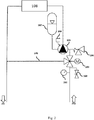
- Fig. 2 illustrates the principal scheme of a heating device with one heat exchanger 108 for one heating circuit.
- the electronically controlled bypass valve integrated into the three-way valve 103 is engaged in the heating system.
- the heating system is equipped as standard with a pump 105 , an expansion vessel 107 , an air vent 106 , a safety valve 104 , a manometer 101 and a discharge valve 102.
- the bypass channel directly connects the heat exchanger 108 to the three-way valve 103 , more specifically to its inlet 8 , through the bypass channel 140 .
- the bypass functions in the three-way valve 103 , it connects the inlet 8 and the output 10 , and furthermore the water is routed to the pump 105 and back to the primary heat exchanger 108 .
- the invention is usable in heating devices, especially in hot water boilers, to prevent damage to the heating device caused either by high pressure differences in the system of radiators and their thermostats or in an emergency shutdown of the system.
- the desired differential pressure of the heating system is adjusted on the spring of an electronically controlled bypass valve integrated into the three-way valve and the valve thus adjusted is engaged in a system with either one or two heating circuits.
- the differential pressure can be electronically adjusted with the same electric drive that electronically controls the three-way valve. While the device is operating, the desired differential pressure for the heating system can be electronically adjusted by changing the preload of the spring in the bypass valve integrated into the three-way value, without needing to exchange springs physically.
Landscapes
- Engineering & Computer Science (AREA)
- General Engineering & Computer Science (AREA)
- Mechanical Engineering (AREA)
- Physics & Mathematics (AREA)
- Thermal Sciences (AREA)
- Chemical & Material Sciences (AREA)
- Combustion & Propulsion (AREA)
- Water Supply & Treatment (AREA)
- Multiple-Way Valves (AREA)
- Steam Or Hot-Water Central Heating Systems (AREA)
Abstract
functions in the three-way valve 103, it connects the inlet 8 and the output 10, and furthermore the water is routed to the pump 105 and back to the primary heat exchanger 108. Industrial Applicability The invention is usable in heating devices, especially in hot water boilers, to prevent damage to the heating device caused either by high pressure differences in the system of radiators and their thermostats or in an emergency shutdown of the system. The desired differential pressure of the heating system is adjusted on the spring of an electronically controlled bypass valve integrated into the three-way valve and the valve thus adjusted is engaged in a system with either one or two heating circuits. The differential pressure can be electronically adjusted with the same electric drive that electronically controls the three-way valve. While the device is operating, the desired differential pressure for the heating system can be electronically adjusted by changing the preload of the spring in the bypass valve integrated into the three-way value, without needing to exchange springs physically. Reference numerals: 1 - Elastic sealing body (movable in the axial direction of the valve spindle)
2 - Elastic sealing body (firmly fixed to the valve spindle)
3 - Stopper
4 - Spring
5 - Valve spindle
6 - Electric Drive
7 - Valve body
8 - Inlet into the electronically controlled three-way valve
9 - Inlet into the electronically controlled three-way valve
10 - Outlet out of the electronically controlled three-way valve
101 - Pressure gauge
102 - Discharge valve
103 - Electronically controlled three-way valve
104 - Safety valve
105 - Pump
106 - Vent valve
107 - Expansion vessel
108 - Primary heat exchanger
109 - Secondary heat exchanger
110 - Service water temperature sensor
120 - Flow sensor with flow restrictor
130 - Service water filter
140 - Bypass channel
HW - Heating water, the arrow indicates the direction to/from the water supply system
DHW - Service water, the arrow indicates the direction to/from the water supply system
Description
- In the prior art, combined heating devices are known, especially hot water boilers, which have a heat source, circulation water pump, and one or two heating circuits, with one circuit intended for space heating and the other circuit for heated service water. In both cases, the heated water is supplied via a common primary heat exchanger and, in the case of heated service water, subsequently distributed also to a secondary heat exchanger.
- A three-way valve is used to switch the supply of water to particular heating circuit and a bypass valve is used to protect the heating system against damage. The bypass valve can be implemented as a single valve or it can be integrated into a three-way valve. The invention describes an electronically adjustable bypass valve integrated into an electronically controlled three-way valve.
- A standard three-way valve used in heating technology is an electronically controlled hydraulic component of a heating apparatus which serves to alter the flow of the heated water, based on the condition and requirements of the heating system. The three-way valve hydraulically integrates the primary heat exchanger into the space heating circuit or into the heated service water circuit.
- In the prior art, standard three-way valves are controlled by an engine, and the publication
DE 10340193 B4 (Vaillant) provides a detailed description of how such a valve operates, wherein a stepping motor drive can be advantegously used as a drive. - In prior art systems, a separate bypass valve is moreover used to prevent damage to the heating device caused either by high pressure differences (henceforth "differential pressures") occurring in the system of radiators and their thermostats or in an emergency shutdown of the system. The bypass valve is used for permanent water pressure equalization between the heating device inlet and outlet.
- When the bypass valve is adjusted to a certain differential pressure, it means the bypass function is set up, it performs a protective function in such a manner: if the space heating suddenly closes, for example due to the poor condition of a radiator, during full operation of the heating device transferring heat exclusively to the space heating circuit, the bypass valve responds to the sudden rise in differential pressure and, in reaching the adjusted differential pressure value, releases heated water through the bypass valve. The bypass valve then discharges heated water from the primary heat exchanger inside the heating device until the heating device evaluates the situation with its own protective elements, responds and shuts off heating mode; in existing heating devices the timing is approximately five (5) seconds. The heating water release via bypass valve inside the heating device protects the primary heat exchange against potential overheating and destruction.
- Since each heating system is unique, characterized by a different number of radiators, filters and other additional equipment, adjustment of the bypass valve needs to be adapted so that the heating device is able to operate as efficiently as possible.
- If the bypass valve is adjusted to a lower differential pressure than is optimal, the heated water is also routed partially and not efficiently through the bypass valve and the heating device becomes less effective.
- If the bypass valve is adjusted to a higher differential pressure than is desired, then the pump feeds an inordinate amount of heated water to the heating circuit, thereby creating noise that is caused by the pumping of a disproportionate amount of heated water through small diameter openings in the thermostatic valves of the radiators. Heated water is not sufficiently taken off and the heating device responds by frequently switching off the heat in order to protect the primary heat exchanger against overheating, and so the heating device becomes less effective.
- The bypass valve has to be connected to the heating system through its own pipelines. An example of a bypass valve engaged in a heating device is described, for instance, in
EP 1595097 B1 (Riello ). Such an established solution is relatively expensive and consumes space, and boiler manufacturers are seeking to integrate the bypass function into a three-way valve, thereby significantly reducing the number of hydraulic circuit components. - When the heating device has two heating circuits and two heat exchangers, the bypass can then run through the body of the secondary heat exchanger and no additional conduit is needed for the bypass valve.
- Such a bypass solution through the body of the secondary heat exchanger is described, for example in
WO 2013104481 A1 (Grundfos ). - Furthermore, patent documents describing a bypass valve function integrated into the three-way valve are disclosed in prior art.
-
WO 01/84026 A1 (Honeywell -
EP 0447851 A2 (Fugas ) describes a three-way valve whose body is equipped with a membrane mechanism and has a fixed spring preload setting. The membrane provides a bypass function and cannot be switched to a differential pressure other than the one set. - Whenever the differential pressure needs to be adjusted to a value other than the preset force of the spring, then, in practice, springs have to be physically exchanged, the servicing of the boiler in the presence of a professional is required and it causes that the boiler is more expensive to operate. This disadvantage is eliminated by the presented invention, which allows the spring preload of the bypass valve integrated in the three-way valve to be adjusted electronically.
- The invention discloses the ability to adjust electronically the preload of a spring in a bypass valve integrated into an electronically controlled three-way valve, thereby eliminating the necessity of physically exchanging springs to accommodate the various differential pressure values desired in a specific heating system. For this purpose, an electric drive is used, which is connected to the three-way valve, with two inlets and one outlet and with the integrated bypass valve into the three-way valve.
- The three-way valve used in heating apparatuses may be controlled by several types of electric drives.
- The invention comprises the utilization of an electric drive, fitted for example with a servomotor or stepper motor, to adjust the various desired preload values for the spring in the bypass valve integrated into the three-way valve. Concurrently, the motor continues to control switching between the outlets of the three-way valve to either the space heating circuit or the heated service water circuit. In addition, there is an option for the deactivating of the bypass function by complete compression of the bypass valve spring, whereby the valve serves, in this case as a standard, as an electronically controlled three-way valve.
- An electric drive fitted with a stepper motor particularly seems suitable for purposes of the presented invention. The stepper motor is a special type of a synchronous motor whose functional movement, i.e. the rotation of the shaft, is not smooth, but it is divided into the number of equally large sub-movements - steps. These motors are applied in tasks to control position and velocity, and in controlling synchronous movements. Stepper motors must be powered by a direct current source and they operate over a single electrical circuit. In normal operation, feedback is not needed to change either velocity or position.
- Variously desired preload values for the spring of the bypass valve integrated into the three-way valve are adjusted by the performance of a specific number of steps in the stepper motor, whereby the existing functional relationship between the number of steps in the stepper motor, the movement of its shaft and the spring preload are utilized.
- Spring preload is adjusted to the desired initial value. This value is defined at delivery of the heating device to the specific heating system. No physical exchange of the spring is necessary while the device is operating and spring preload corresponding to the desired differential pressure can be practically adjusted through a user interface to the heating device, like a boiler, via control buttons on an electronic pad or touchscreen, or other available electronic means using the aplication software.
- The invention is further explained in drawings, but not limited to them.
-
Fig. 1a : Connection diagram of a three-way valve with an integrated bypass valve in a heating device comprising two heating circuits, and with two heat exchangers and a bypass channel -
Fig. 1b : Connection diagram of a three-way valve with an integrated bypass valve in a heating device comprising two heating circuits, and with two heat exchangers, no bypass channel and the bypass running through the body of the secondary heat exchanger -
Fig. 2 : Connection diagram of a three-way valve with an integrated bypass valve in a heating device comprising one heating circuit, and with one heat exchanger. -
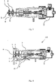
Fig. 3 : Schematic representation of a three-way valve with an integrated bypass valve. -
Fig. 4 : Valve in operation with heated water routed into the space heating circuit and with the bypass valve functioning, with a initialized value of differential pressure. -
Fig. 5 : Valve in operation with heated water routed into the secondary heat exchanger in the heated service water circuit, without the bypass valve functioning. -
Fig. 6 : Valve in operation with heated water routed into the space heating circuit and with the bypass valve functioning, with other than the initalized value of differential pressure. -
Fig. 7 : Valve with deactivated bypass function, where the valve works as a standard three-way valve. - The invention is further explained with the aid of
Figures 1-6 , wherein the three-way valve 103, comprising abody 7 and anelectric drive 6, fitted with a stepper motor, is used as a control valve. A stepper motor with a maximum linear stroke of 12 mm and a micro-step of 0.042 mm is used in this embodiment of the invention. - The three-way valve has two
inlets outlet 10. Thebody 7 of the three-way valve 103 is connected to the shaft of theelectric drive 6 through aspindle 5. In thebody 7, on thespindle 5, there is aspring 4 configured with a certain preload and its ends are clamped between two elastic sealing bodies 1 a 2 in a substantially semispherical shape. One of the sealing bodies moves freely in the axial direction of the spindle 5 (sealingbody 1 in the drawings), while the other body (sealingbody 2 in the drawings) is in a fixed position on thespindle 5. Thus, the integrated bypass valve is designed with aspring 4 and twoelastic sealing bodies - All illustrations on
Figures 3-7 take such a configuration for the three-way valve 103 into account, where oneelastic sealing body 2 is in a fixed position on thespindle 5, mechanically locked with stoppers, for example, and theother sealing body 1 moves in the axial direction of thespindle 5, since astopper 3 limiting movement is positioned on only one side of theelastic body 1. It is clear that the three-way valve 103 may be configured in another manner with the integrated bypass valve, for example so that thestopper 3 is placed at theelastic body 2, theelastic sealing body 2 moves freely in the axial direction of thespindle 5 in the three-way valve 103 and theelastic sealing body 1 is in a fixed position mechanically locked by the stoppers on thespindle 5 in the three-way valve 103. Another variant embodying the invention is for the sealing bodies to be mechanically fastened to the spring, wherein the difference from the described embodiment is that the spring is only clamped between the sealing bodies.
The situation is schematically illustrated inFigure 4 , with thevalve 103 operating as a three-way valve. Oneinlet 9 is connected to theoutlet 10 and the valve acts as a three-way valve, with heated water routed to the space heating circuit. Theother inlet 8 is closed off by the sealingelement 1. At the same time, the valve acts as a bypass valve and thespring 4 is set at the desired, initialized differential pressure.
The bypass valve functions in the following manner: When pressure rises at the outlet HW from the heating device and exceeds the maximum desired value compared to the pressure HW at the inlet to the heating device, the pressure of the water acts on the sealingelement 1 andspring 4. The spring compresses at the appropriately set preload and theinlet 8 opens up in the valve. Water flows from theinlet 8 to theoutlet 10.
Figure 5 schematically illustrates thevalve 103 operating as a three-way valve, theinlet 8 is connected to theoutlet 10, theinlet 9 is closed off by the sealingelement 2 and the heated water is routed to thesecondary heat exchanger 109 in the heated service water circuit. The bypass valve function is not implemented because there is no need in this operating condition to protect the primary heat exchanger.
Figure 6 illustrates thevalve 103 operating as a three-way valve in the same operating condition as inFigure 4 , but thespring 4 has been set to a value other than the initialized value using a stepper motor and, in the illustrated case, to a higher desired differential pressure, as evidenced by the greater compression of thespring 4 in comparison to the compression of thespring 4 inFigure 4 .
Figure 7 illustrates the bypass valve integrated into the three-way valve 103 when it is shut off. A stepper motor fully presses thespring 4 down and neither fullymovable sealing elements 1 nor 2 can shift in the axial direction of thespindle 5 in thevalve 103. The bypass valve cannot be used, theinlet 9 is connected to theoutlet 10 into the hot water circuit and thevalve 103 exclusively functions as a standard three-way valve. Such a mode of operation for the valve is the preferred use of the presented invention and is designed especially when servicing the heating device. - The invention for an electronically adjustable bypass valve integrated into an electronically controlled three-way valve, performing as described, can be used in a heating system with one or two heating circuits, with one or two heat exchangers.
-
Figure 1a shows the principal scheme of the heating device with twoheat exchangers pump 105, anexpansion vessel 107, anair vent 106, asafety valve 104, atemperature sensor 110, aflow sensor 120, afilter 130, amanometer 101, adischarge valve 102 and abypass channel 140. The electronically controlled bypass valve integrated into the three-way valve 103 is engaged in the heating system. Thebypass channel 140 circulates water so that the water heated in theheat exchanger 108 will not flow back into the system through the outlet HW, but would be instead routed through thebypass channel 140 into the three-way valve 103 at itsinlet 8. When the bypass functions in the three-way valve 103, it connects theinlet 8 and theoutput 10, and furthermore the water is routed to thepump 105 and back to theprimary heat exchanger 108. -
Figure 1b shows the principal scheme of the heating device with twoheat exchangers pump 105, anexpansion vessel 107, anair vent 106, asafety valve 104, atemperature sensor 110, aflow sensor 120, afilter 130, amanometer 101 and adischarge valve 102. The electronically controlled bypass valve integrated into the three-way valve 103 is engaged in the heating system. The bypass channel runs through the body of thesecondary heat exchanger 109. Internal circulation is provided in the functioning of the bypass so that the water heated in theheat exchanger 108 will not flow back into the system through the outlet HW, but would be instead routed through theheat exchanger 109 into the three-way valve 103 at itsinlet 8. When the bypass functions in the three-way valve 103, it connects theinlet 8 and theoutput 10, and furthermore the water is routed to thepump 105 and back to theprimary heat exchanger 108.
Fig. 2 illustrates the principal scheme of a heating device with oneheat exchanger 108 for one heating circuit. The electronically controlled bypass valve integrated into the three-way valve 103 is engaged in the heating system. The heating system is equipped as standard with apump 105, anexpansion vessel 107, anair vent 106, asafety valve 104, amanometer 101 and adischarge valve 102. The bypass channel directly connects theheat exchanger 108 to the three-way valve 103, more specifically to itsinlet 8, through thebypass channel 140. When the bypass functions in the three-way valve 103, it connects theinlet 8 and theoutput 10, and furthermore the water is routed to thepump 105 and back to theprimary heat exchanger 108. - The invention is usable in heating devices, especially in hot water boilers, to prevent damage to the heating device caused either by high pressure differences in the system of radiators and their thermostats or in an emergency shutdown of the system. The desired differential pressure of the heating system is adjusted on the spring of an electronically controlled bypass valve integrated into the three-way valve and the valve thus adjusted is engaged in a system with either one or two heating circuits. The differential pressure can be electronically adjusted with the same electric drive that electronically controls the three-way valve. While the device is operating, the desired differential pressure for the heating system can be electronically adjusted by changing the preload of the spring in the bypass valve integrated into the three-way value, without needing to exchange springs physically.
-
- 1 - Elastic sealing body (movable in the axial direction of the valve spindle)
- 2 - Elastic sealing body (firmly fixed to the valve spindle)
- 3 - Stopper
- 4 - Spring
- 5 - Valve spindle
- 6 - Electric Drive
- 7 - Valve body
- 8 - Inlet into the electronically controlled three-way valve
- 9 - Inlet into the electronically controlled three-way valve
- 10 - Outlet out of the electronically controlled three-way valve
- 101 - Pressure gauge
- 102 - Discharge valve
- 103 - Electronically controlled three-way valve
- 104 - Safety valve
- 105 - Pump
- 106 - Vent valve
- 107 - Expansion vessel
- 108 - Primary heat exchanger
- 109 - Secondary heat exchanger
- 110 - Service water temperature sensor
- 120 - Flow sensor with flow restrictor
- 130 - Service water filter
- 140 - Bypass channel
- HW - Heating water, the arrow indicates the direction to/from the water supply system
- DHW - Service water, the arrow indicates the direction to/from the water supply system
Claims (3)
- An electronically adjustable bypass valve integrated into an electronically controlled three-way valve (103) with two inlets (8, 9) and one outlet (10), engaged in a heating device comprising a circulation pump (105), wherein the heating device has one or two heating circuits and a primary heat exchanger (108) is engaged for space heating circuit and a secondary heat exchanger (109) is engaged for heated service water circuit, and the three-way electronically controlled valve (103) is assembled from a body (7) and spindle (5), whereon the spindle (5) is configured with a spring (4), the ends of which are clamped between two elastic sealing bodies (1, 2) in a substantially semispherical shape, placed on the spindle (5) so one of the elastic sealing bodies (1, 2), placed at either end of the spring (4), is firmly attached to the spindle (5) and the other flexible sealing body (1, 2), placed at the other end of the spring (4), moves freely in the axial direction of the valve spindle (5),
characterized in that
there is an electric drive (6) with a linear stroke attached to the valve (103) to adjust the preload on the spring (4). - The electronically adjustable bypass valve integrated into the electronically controlled three-way valve (103) of claim 1,
characterized in that
it comprises the spring (4) in the fully compressed state to deactivate the bypass function. - The electronically adjustable bypass valve integrated into the electronically controlled three-way valve (103) of anyone of the claim 1 or claim 2,
characterized in that
the electric drive (6) is fitted with a stepper motor.
Applications Claiming Priority (1)
| Application Number | Priority Date | Filing Date | Title |
|---|---|---|---|
| SK148-2017U SK8116Y1 (en) | 2017-06-16 | 2017-06-16 | Electronically adjustable bypass valve integrated into an electronically controlled three-way valve |
Publications (1)
| Publication Number | Publication Date |
|---|---|
| EP3428546A1 true EP3428546A1 (en) | 2019-01-16 |
Family
ID=60788202
Family Applications (1)
| Application Number | Title | Priority Date | Filing Date |
|---|---|---|---|
| EP18175069.6A Withdrawn EP3428546A1 (en) | 2017-06-16 | 2018-05-30 | Electronically adjustable bypass valve integrated into the electronically controlled three-way valve |
Country Status (3)
| Country | Link |
|---|---|
| EP (1) | EP3428546A1 (en) |
| CN (1) | CN109140784A (en) |
| SK (1) | SK8116Y1 (en) |
Cited By (4)
| Publication number | Priority date | Publication date | Assignee | Title |
|---|---|---|---|---|
| CN110779219A (en) * | 2019-11-05 | 2020-02-11 | 宁波方太厨具有限公司 | Water heater and water temperature control method thereof |
| EP3982057A1 (en) * | 2020-10-09 | 2022-04-13 | Vaillant GmbH | Hot water heating device |
| WO2022144151A1 (en) * | 2021-01-04 | 2022-07-07 | Bosch Termoteknik Isitmave Klima Sanayi Ticaret Anonim Sirketi | Method for operating a heater and heater for heating a space and/or a flow of drinking water |
| DE102022100341A1 (en) | 2022-01-10 | 2023-07-13 | Vaillant Gmbh | Heating device, method for operating a heating device, computer program product, regulation and control device and use of a stepping motor valve |
Families Citing this family (2)
| Publication number | Priority date | Publication date | Assignee | Title |
|---|---|---|---|---|
| DE102018114849A1 (en) * | 2018-06-20 | 2019-12-24 | Johnson Electric Germany GmbH & Co. KG | Sealing system for switchable water valves |
| IT201900002455A1 (en) * | 2019-02-20 | 2020-08-20 | Elbi Int Spa | Hydraulic system for a heating and domestic hot water generation system. |
Citations (10)
| Publication number | Priority date | Publication date | Assignee | Title |
|---|---|---|---|---|
| EP0447851A2 (en) | 1990-03-08 | 1991-09-25 | FUGAS s.r.l. | An improved three-way valve |
| DE69502536T2 (en) * | 1994-04-25 | 1998-12-03 | Chaffoteaux Et Maury, Chatou | Electrically controlled 3-way valve |
| DE19837012A1 (en) * | 1998-08-14 | 2000-02-24 | Honeywell Ag | Heat exchanger connection fitting complete with three-way valve uses differential pressure overflow valve between exchanger connections in fitting-parallel pipe permitting adjustable pressure setting |
| EP0994311A2 (en) * | 1998-10-14 | 2000-04-19 | FUGAS s.r.l. | Hydraulic assembly for heating systems also supplying sanitary water, equipped with a hot water tank |
| WO2001084026A1 (en) | 2000-04-29 | 2001-11-08 | Honeywell B.V. | Three-way valve comprising an integrated bypass valve |
| EP1653132A1 (en) * | 2004-11-02 | 2006-05-03 | Siemens Aktiengesellschaft | Three-way valve |
| EP1595097B1 (en) | 2003-02-21 | 2007-04-04 | Riello S.p.A. | Gas boiler |
| CN101576281A (en) * | 2008-05-05 | 2009-11-11 | 浙江春晖智能控制股份有限公司 | Two-in-one-out switching waterway module with built-in sealing components |
| WO2013104481A1 (en) | 2012-01-09 | 2013-07-18 | Grundfos Holding A/S | Heating unit |
| DE10340193B4 (en) | 2002-09-02 | 2017-05-24 | Vaillant Gmbh | Method for operating a hydraulic changeover valve |
-
2017
- 2017-06-16 SK SK148-2017U patent/SK8116Y1/en unknown
-
2018
- 2018-05-30 EP EP18175069.6A patent/EP3428546A1/en not_active Withdrawn
- 2018-06-08 CN CN201810583766.5A patent/CN109140784A/en active Pending
Patent Citations (10)
| Publication number | Priority date | Publication date | Assignee | Title |
|---|---|---|---|---|
| EP0447851A2 (en) | 1990-03-08 | 1991-09-25 | FUGAS s.r.l. | An improved three-way valve |
| DE69502536T2 (en) * | 1994-04-25 | 1998-12-03 | Chaffoteaux Et Maury, Chatou | Electrically controlled 3-way valve |
| DE19837012A1 (en) * | 1998-08-14 | 2000-02-24 | Honeywell Ag | Heat exchanger connection fitting complete with three-way valve uses differential pressure overflow valve between exchanger connections in fitting-parallel pipe permitting adjustable pressure setting |
| EP0994311A2 (en) * | 1998-10-14 | 2000-04-19 | FUGAS s.r.l. | Hydraulic assembly for heating systems also supplying sanitary water, equipped with a hot water tank |
| WO2001084026A1 (en) | 2000-04-29 | 2001-11-08 | Honeywell B.V. | Three-way valve comprising an integrated bypass valve |
| DE10340193B4 (en) | 2002-09-02 | 2017-05-24 | Vaillant Gmbh | Method for operating a hydraulic changeover valve |
| EP1595097B1 (en) | 2003-02-21 | 2007-04-04 | Riello S.p.A. | Gas boiler |
| EP1653132A1 (en) * | 2004-11-02 | 2006-05-03 | Siemens Aktiengesellschaft | Three-way valve |
| CN101576281A (en) * | 2008-05-05 | 2009-11-11 | 浙江春晖智能控制股份有限公司 | Two-in-one-out switching waterway module with built-in sealing components |
| WO2013104481A1 (en) | 2012-01-09 | 2013-07-18 | Grundfos Holding A/S | Heating unit |
Cited By (5)
| Publication number | Priority date | Publication date | Assignee | Title |
|---|---|---|---|---|
| CN110779219A (en) * | 2019-11-05 | 2020-02-11 | 宁波方太厨具有限公司 | Water heater and water temperature control method thereof |
| CN110779219B (en) * | 2019-11-05 | 2021-02-12 | 宁波方太厨具有限公司 | Water heater and water temperature control method thereof |
| EP3982057A1 (en) * | 2020-10-09 | 2022-04-13 | Vaillant GmbH | Hot water heating device |
| WO2022144151A1 (en) * | 2021-01-04 | 2022-07-07 | Bosch Termoteknik Isitmave Klima Sanayi Ticaret Anonim Sirketi | Method for operating a heater and heater for heating a space and/or a flow of drinking water |
| DE102022100341A1 (en) | 2022-01-10 | 2023-07-13 | Vaillant Gmbh | Heating device, method for operating a heating device, computer program product, regulation and control device and use of a stepping motor valve |
Also Published As
| Publication number | Publication date |
|---|---|
| SK8116Y1 (en) | 2018-06-01 |
| SK1482017U1 (en) | 2018-01-04 |
| CN109140784A (en) | 2019-01-04 |
Similar Documents
| Publication | Publication Date | Title |
|---|---|---|
| SK1482017U1 (en) | Electronically adjustable bypass valve integrated into an electronically controlled three-way valve | |
| US11073290B2 (en) | Circulation pump assembly for a heating and/or cooling system | |
| RU2535828C2 (en) | Vehicle extra heater system | |
| CN105745450B (en) | Electronic cooling medium pump | |
| CN106014590B (en) | Multi-way valve with modular rotary member | |
| US4150788A (en) | Remote-controlled central air-conditioning system | |
| CN104040261B (en) | Heating plant | |
| CN105531519A (en) | Fail safety control valve of cooling water | |
| CN109844277A (en) | Electronic coolant pump | |
| EP1452706A1 (en) | Thermostat | |
| EP0812280A1 (en) | Automotive hydraulic system and method | |
| JP2005061417A (en) | Engine cooling disc valve | |
| EP3800387B1 (en) | By-pass valve | |
| CN113586759B (en) | Temperature control valve, return valve and water supply system | |
| US20150158376A1 (en) | Air Flap Device | |
| WO2018111672A1 (en) | Thermostatic valve for an internal combustion engine | |
| CN109937302B (en) | System for screw compressors for commercial vehicles | |
| CN114763840A (en) | Gas proportional valve and gas water heater with same | |
| EP2660495B1 (en) | Control valve unit of a liquid circuit of an internal combustion engine | |
| KR101610412B1 (en) | Ion Filter Device in Fuel Cell Electric Vehicle | |
| KR101991500B1 (en) | Pneumatic actuator, pneumatic valve using the same and pneumatic valve system using the same | |
| EP2642170B1 (en) | Domestic water flow regulator and hydraulic unit in which it is included | |
| US20180283559A1 (en) | Hydraulic system | |
| CN211953850U (en) | Integral type heat exchanger group with flexible man-machine interface | |
| RU2686959C1 (en) | Bus-type actuating device with valve group control function |
Legal Events
| Date | Code | Title | Description |
|---|---|---|---|
| PUAI | Public reference made under article 153(3) epc to a published international application that has entered the european phase |
Free format text: ORIGINAL CODE: 0009012 |
|
| PUAB | Information related to the publication of an a document modified or deleted |
Free format text: ORIGINAL CODE: 0009199EPPU |
|
| PUAI | Public reference made under article 153(3) epc to a published international application that has entered the european phase |
Free format text: ORIGINAL CODE: 0009012 |
|
| AK | Designated contracting states |
Kind code of ref document: A1 Designated state(s): AL AT BE BG CH CY CZ DE DK EE ES FI FR GB GR HR HU IE IS IT LI LT LU LV MC MK MT NL NO PL PT RO RS SE SI SK SM TR |
|
| AX | Request for extension of the european patent |
Extension state: BA ME |
|
| STAA | Information on the status of an ep patent application or granted ep patent |
Free format text: STATUS: THE APPLICATION IS DEEMED TO BE WITHDRAWN |
|
| 18D | Application deemed to be withdrawn |
Effective date: 20190717 |