EP3428543A1 - Range hood and housing component thereof - Google Patents
Range hood and housing component thereof Download PDFInfo
- Publication number
- EP3428543A1 EP3428543A1 EP18179132.8A EP18179132A EP3428543A1 EP 3428543 A1 EP3428543 A1 EP 3428543A1 EP 18179132 A EP18179132 A EP 18179132A EP 3428543 A1 EP3428543 A1 EP 3428543A1
- Authority
- EP
- European Patent Office
- Prior art keywords
- power supply
- supply module
- voltage power
- range hood
- electrostatic absorption
- Prior art date
- Legal status (The legal status is an assumption and is not a legal conclusion. Google has not performed a legal analysis and makes no representation as to the accuracy of the status listed.)
- Granted
Links
Images

Classifications
-
- F—MECHANICAL ENGINEERING; LIGHTING; HEATING; WEAPONS; BLASTING
- F24—HEATING; RANGES; VENTILATING
- F24C—DOMESTIC STOVES OR RANGES ; DETAILS OF DOMESTIC STOVES OR RANGES, OF GENERAL APPLICATION
- F24C15/00—Details
- F24C15/20—Removing cooking fumes
- F24C15/2035—Arrangement or mounting of filters
-
- B—PERFORMING OPERATIONS; TRANSPORTING
- B03—SEPARATION OF SOLID MATERIALS USING LIQUIDS OR USING PNEUMATIC TABLES OR JIGS; MAGNETIC OR ELECTROSTATIC SEPARATION OF SOLID MATERIALS FROM SOLID MATERIALS OR FLUIDS; SEPARATION BY HIGH-VOLTAGE ELECTRIC FIELDS
- B03C—MAGNETIC OR ELECTROSTATIC SEPARATION OF SOLID MATERIALS FROM SOLID MATERIALS OR FLUIDS; SEPARATION BY HIGH-VOLTAGE ELECTRIC FIELDS
- B03C3/00—Separating dispersed particles from gases or vapour, e.g. air, by electrostatic effect
- B03C3/02—Plant or installations having external electricity supply
- B03C3/025—Combinations of electrostatic separators, e.g. in parallel or in series, stacked separators or dry-wet separator combinations
-
- B—PERFORMING OPERATIONS; TRANSPORTING
- B03—SEPARATION OF SOLID MATERIALS USING LIQUIDS OR USING PNEUMATIC TABLES OR JIGS; MAGNETIC OR ELECTROSTATIC SEPARATION OF SOLID MATERIALS FROM SOLID MATERIALS OR FLUIDS; SEPARATION BY HIGH-VOLTAGE ELECTRIC FIELDS
- B03C—MAGNETIC OR ELECTROSTATIC SEPARATION OF SOLID MATERIALS FROM SOLID MATERIALS OR FLUIDS; SEPARATION BY HIGH-VOLTAGE ELECTRIC FIELDS
- B03C3/00—Separating dispersed particles from gases or vapour, e.g. air, by electrostatic effect
- B03C3/34—Constructional details or accessories or operation thereof
- B03C3/36—Controlling flow of gases or vapour
- B03C3/368—Controlling flow of gases or vapour by other than static mechanical means, e.g. internal ventilator or recycler
-
- B—PERFORMING OPERATIONS; TRANSPORTING
- B03—SEPARATION OF SOLID MATERIALS USING LIQUIDS OR USING PNEUMATIC TABLES OR JIGS; MAGNETIC OR ELECTROSTATIC SEPARATION OF SOLID MATERIALS FROM SOLID MATERIALS OR FLUIDS; SEPARATION BY HIGH-VOLTAGE ELECTRIC FIELDS
- B03C—MAGNETIC OR ELECTROSTATIC SEPARATION OF SOLID MATERIALS FROM SOLID MATERIALS OR FLUIDS; SEPARATION BY HIGH-VOLTAGE ELECTRIC FIELDS
- B03C3/00—Separating dispersed particles from gases or vapour, e.g. air, by electrostatic effect
- B03C3/34—Constructional details or accessories or operation thereof
- B03C3/40—Electrode constructions
- B03C3/41—Ionising-electrodes
-
- B—PERFORMING OPERATIONS; TRANSPORTING
- B03—SEPARATION OF SOLID MATERIALS USING LIQUIDS OR USING PNEUMATIC TABLES OR JIGS; MAGNETIC OR ELECTROSTATIC SEPARATION OF SOLID MATERIALS FROM SOLID MATERIALS OR FLUIDS; SEPARATION BY HIGH-VOLTAGE ELECTRIC FIELDS
- B03C—MAGNETIC OR ELECTROSTATIC SEPARATION OF SOLID MATERIALS FROM SOLID MATERIALS OR FLUIDS; SEPARATION BY HIGH-VOLTAGE ELECTRIC FIELDS
- B03C3/00—Separating dispersed particles from gases or vapour, e.g. air, by electrostatic effect
- B03C3/34—Constructional details or accessories or operation thereof
- B03C3/40—Electrode constructions
- B03C3/45—Collecting-electrodes
- B03C3/47—Collecting-electrodes flat, e.g. plates, discs, gratings
-
- B—PERFORMING OPERATIONS; TRANSPORTING
- B03—SEPARATION OF SOLID MATERIALS USING LIQUIDS OR USING PNEUMATIC TABLES OR JIGS; MAGNETIC OR ELECTROSTATIC SEPARATION OF SOLID MATERIALS FROM SOLID MATERIALS OR FLUIDS; SEPARATION BY HIGH-VOLTAGE ELECTRIC FIELDS
- B03C—MAGNETIC OR ELECTROSTATIC SEPARATION OF SOLID MATERIALS FROM SOLID MATERIALS OR FLUIDS; SEPARATION BY HIGH-VOLTAGE ELECTRIC FIELDS
- B03C3/00—Separating dispersed particles from gases or vapour, e.g. air, by electrostatic effect
- B03C3/34—Constructional details or accessories or operation thereof
- B03C3/66—Applications of electricity supply techniques
-
- B—PERFORMING OPERATIONS; TRANSPORTING
- B03—SEPARATION OF SOLID MATERIALS USING LIQUIDS OR USING PNEUMATIC TABLES OR JIGS; MAGNETIC OR ELECTROSTATIC SEPARATION OF SOLID MATERIALS FROM SOLID MATERIALS OR FLUIDS; SEPARATION BY HIGH-VOLTAGE ELECTRIC FIELDS
- B03C—MAGNETIC OR ELECTROSTATIC SEPARATION OF SOLID MATERIALS FROM SOLID MATERIALS OR FLUIDS; SEPARATION BY HIGH-VOLTAGE ELECTRIC FIELDS
- B03C2201/00—Details of magnetic or electrostatic separation
- B03C2201/04—Ionising electrode being a wire
Definitions
- the present application relates to the field of range hoods, and in particular to the field of housing components of range hoods.
- the range hood is usually further provided with a high-voltage power supply module that supplies power to the electrostatic absorption apparatus.
- the high-voltage power supply module of the conventional range hood is usually mounted and disposed in an electric box of the range hood, and supplies power to the electrostatic absorption apparatus through a high-voltage direct current power supply wire.
- the high-voltage direct current power supply wire usually transmits a high voltage of thousands of volts, and has hidden dangers once it is shorted or short-circuited, or directly contacts with a human body.
- the present application provides an improved range hood and a housing component thereof, so as to solve at least one of the foregoing problems.
- the range hood provided by the present application includes an electrostatic absorption apparatus and a high-voltage power supply module that supplies power to the electrostatic absorption apparatus, and the high-voltage power supply module supplies power to the electrostatic absorption apparatus by means of insertion connection. If the technical solution of the present application is adopted, the high-voltage direct current power supply wire does not need to be provided, thereby reducing hidden dangers.
- the range hood further includes an accommodation cavity adapted to accommodate the electrostatic absorption apparatus, and the high-voltage power supply module is used as a partial wall body of the accommodation cavity.
- the electrostatic absorption apparatus and the high-voltage power supply module are adjacent to each other and can be connected by insertion easily.
- the high-voltage power supply module is used as at least a partial rear wall of the accommodation cavity, the accommodation cavity includes a placement opening, and the electrostatic absorption apparatus is disposed to adapt to penetrate through the placement opening to be placed in the accommodation cavity toward the rear wall of the accommodation cavity till the electrostatic absorption apparatus is connected to the high-voltage power supply module by insertion.
- the electrostatic absorption apparatus and the high-voltage power supply module are adjacent to each other, and can be connected by insertion easily.
- the accommodation cavity includes a placement opening and a rear wall gap disposed opposite to each other and the high-voltage power supply module blocks the rear wall gap.
- the electrostatic absorption apparatus and the high-voltage power supply module are adjacent to each other, and can be connected by insertion easily.
- one of the high-voltage power supply module and the electrostatic absorption apparatus is provided with a plug portion, and the other of the high-voltage power supply module and the electrostatic absorption apparatus is provided with a socket portion adapted to connect to the plug portion by insertion.
- the socket portion includes an insertion connection spring.
- the plug portion is disposed on the electrostatic absorption apparatus, and the plug portion includes a ground electrode plug portion, an absorption electrode plug portion, and an ionization electrode plug portion sequentially arranged.
- the ground electrode plug portion and the ionization electrode plug portion that have a large voltage difference have a long creepage distance there-between, thereby reducing or avoiding a creepage phenomenon.
- At least one insulation isolation wall is disposed between the ground electrode plug portion and the absorption electrode plug portion and at least two insulation isolation walls are disposed between the absorption electrode plug portion and the ionization electrode plug portion, thereby reducing or avoiding a creepage phenomenon.
- the high-voltage power supply module includes a mains power supply wire or a low-voltage direct current power supply wire used to supply power to the high-voltage power supply module.
- the range hood further includes a housing, the housing includes a gap portion, and the high-voltage power supply module blocks the gap portion, thereby reducing the thickness of the range hood.
- the accommodation cavity is provided with a bottom air inlet and a top air outlet.
- the range hood further includes a fan and the fan is located above the top air outlet of the accommodation cavity.
- the range hood further includes a filter net, and the filter net is located below the bottom air inlet of the accommodation cavity.
- the present application further provides a housing component of a range hood that includes a housing, the housing including an accommodation cavity adapted to accommodate an electrostatic absorption apparatus, and further includes a high-voltage power supply module adapted to supply power to the electrostatic absorption apparatus.
- the high-voltage power supply module is fixed on the housing and includes a plug portion or a socket portion used to supply power to the electrostatic absorption apparatus. If the technical solution of the present application is adopted, the high-voltage direct current power supply wire does not need to be provided, thereby reducing hidden dangers.
- the high-voltage power supply module is used as a partial wall body of the accommodation cavity.
- the electrostatic absorption apparatus and the high-voltage power supply module are adjacent to each other, and can be connected by insertion easily.
- the housing includes a gap portion and the high-voltage power supply module blocks the gap portion, thereby reducing the thickness of the housing component.
- the housing further includes a chassis and a smoke collection cover and the accommodation cavity is located between the chassis and the smoke collection cover.
- azimuth expressions such as “rear wall”, “bottom air inlet , “top air outlet”, “above”, “under”, “bottom”, “bottom surface”, “top surface”, and “side surface” in the present application refer to common use states of a range hood if no particular indication is provided.
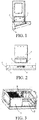
- the present application provides an embodiment of a range hood, including a fan, a filter net 5, an oil cup 6, a chassis 3, a smoke collection cover 4, a decorative cover, an electrostatic absorption apparatus 1, a high-voltage power supply module 2 that is used to supply power to the electrostatic absorption apparatus 1 directly, and an accommodation cavity 7 adapted to accommodate the electrostatic absorption apparatus 1, as shown in FIGs. 1 and 2 .
- the fan is disposed in the chassis 3.
- the oil cup 6 is fixed on a bottom end of the smoke collection cover 4.
- the accommodation cavity 7 is located between the chassis 3 and the smoke collection cover 4.
- the accommodation cavity 7 is provided with a bottom air inlet and a top air outlet, as shown in FIG. 3 . Specifically, the fan is located above the top air outlet of the accommodation cavity 7, and the filter net 5 is located below the bottom air inlet of the accommodation cavity 7.
- the electrostatic absorption apparatus 1 includes an absorption electrode plate and an ionization wire. There are two electrostatic absorption apparatuses 1, and the two electrostatic absorption apparatuses 1 are arranged in the accommodation cavity 7 in parallel. In FIG. 3 , the left electrostatic absorption apparatus 1 is accommodated in the accommodation cavity 7, but the right one 1 is not accommodated yet.
- the structures of the electrostatic absorption apparatus 1 are the same and the installation positions thereof can be exchanged.
- the accommodation cavity 7 is cuboid, as shown in FIG. 3 , the bottom air inlet is located on the bottom surface of the cuboid accommodation cavity 7, and the top air outlet is located on the top surface of the cuboid accommodation cavity 7.
- the accommodation cavity 7 includes a placement opening and a rear wall gap disposed opposite to each other. The placement opening is located on a side surface of the accommodation cavity 7.
- the high-voltage power supply module 2 blocks the rear wall gap.
- the high-voltage power supply module 2 is used as a partial wall body of the accommodation cavity 7, and specifically, the high-voltage power supply module 2 is used as a rear wall of the accommodation cavity 7.
- the electrostatic absorption apparatus 1 is disposed to adapt to penetrate through the placement opening to be placed in the accommodation cavity 7 in a horizontal direction toward the rear wall of the accommodation cavity 7, till the electrostatic absorption apparatus 1 is connected to the high-voltage power supply module 2 by insertion, as shown in FIGs. 1 and 2 .
- the decorative cover (not shown) is placed on the smoke collection cover 4 so as to shield the chassis 3 and the electrostatic absorption apparatus 1.
- the high-voltage power supply module 2 also called as a high-voltage generator, has an English abbreviation HVPS (high voltage power supply).
- the high-voltage power supply module 2 includes a mains power supply wire that is used to supply power to the high-voltage power supply module 2.
- the mains power supply wire provides a 220v alternating current to the high-voltage power supply module 2.
- the high-voltage power supply module 2 supplies power to the electrostatic absorption apparatus 1 by means of insertion connection, that is, when the high-voltage power supply module 2 and the electrostatic absorption apparatus 1 are connected by insertion, the high-voltage power supply module 2 and the electrostatic absorption apparatus 1 are electrically connected, and the high-voltage power supply module 2 supplies a high-voltage direct current required by operation of the electrostatic absorption apparatus 1 to the electrostatic absorption apparatus 1 through the insertion position.
- the rear side wall of the high-voltage power supply module 2 is exposed outside and faces an installation wall (in this embodiment, the range hood is fixed on the installation wall).
- the electrostatic absorption apparatus 1 is provided with a plug portion, the high-voltage power supply module 2 is provided with a socket portion adapted to connect to the plug portion by insertion.
- the plug portion of the electrostatic absorption apparatus 1 includes a ground electrode plug portion 9, an absorption electrode plug portion 10, and an ionization electrode plug portion 11 sequentially arranged, as shown in FIG. 5 .
- the absorption electrode plug portion 10 is electrically connected to the absorption electrode plate of the electrostatic absorption apparatus 1.
- the ionization electrode plug portion 11 is electrically connected to the ionization wire of the electrostatic absorption apparatus 1.
- the high-voltage power supply module 2 is provided with three socket portions that are one-to-one corresponding to the ground electrode plug portion 9, the absorption electrode plug portion 10, and the ionization electrode plug portion 11 of the electrostatic absorption apparatus 1.
- Each socket portion has the same structure and includes insertion connection spring 8.
- the socket portion that is connected to and cooperates with the ground electrode plug portion 9 by insertion shown in FIG. 4 includes two insertion connection springs 8 that have a gap there-between.
- the ground electrode plug portion 9 When the ground electrode plug portion 9 is inserted into the gap, the two insertion connection springs 8 are deformed elastically to be far away from each other (the gap become large), the ground electrode plug portion 9 is held by the two insertion connection springs 8, and the high-voltage power supply module 2 and the electrostatic absorption apparatus 1 are connected by insertion. At this time, if a user extracts the electrostatic absorption apparatus 1 from the accommodation cavity 7, the ground electrode plug portion 9 is separated from the two insertion connection springs 8, and the two insertion connection springs 8 are recovered from the elastic deformation. It should be noted herein that, since there are two electrostatic absorption apparatuses 1, the high-voltage power supply module 2 has six socket portions in total correspondingly.
- the mains power supply wire that is used to supply power to the high-voltage power supply module can be replaced as the low-voltage direct current power supply wire, and one end of the low-voltage direct current power supply wire is electrically connected to the high-voltage power supply module, and the other end is electrically connected to an electric box of the range hood.
- the electrostatic absorption apparatus is provided with a socket portion and the high-voltage power supply module is provided with a plug portion adapted to connect to the socket portion by insertion.
- the specific structures of the plug portion and the socket portion and the cooperation manner are not limited to this embodiment, and similar technical solutions of insertion connection in the prior art may also be referred to, for example, the cooperation structure of the power supply plug and the socket.
- the present application further provides an embodiment of a housing component of a range hood that includes a housing and a high-voltage power supply module adapted to supply power to an electrostatic absorption apparatus.
- the housing includes an accommodation cavity adapted to accommodate the electrostatic absorption apparatus, and the high-voltage power supply module is used as a partial wall body of the accommodation cavity.
- the high-voltage power supply module is fixed to the housing.
- the high-voltage power supply module includes a socket portion that is used to supply power to the electrostatic absorption apparatus.
- an electrostatic absorption apparatus is installed into the accommodation cavity of the housing component, one end surface of the electrostatic absorption apparatus is attached to the high-voltage power supply module, and the electrostatic absorption apparatus and the high-voltage power supply module are connected by insertion.
- the corresponding electrostatic absorption apparatus needs to be provided with a plug portion matching the socket portion of the housing component.
- the housing may also include a chassis and a smoke collection cover, and the accommodation cavity is located between the chassis and the smoke collection cover.
- the high-voltage power supply module may also be disposed in the housing, and specifically, the high-voltage power supply module is attached onto the inner wall of the housing.
- the housing may also include a gap portion, and the high-voltage power supply module blocks the gap portion.
Landscapes
- Engineering & Computer Science (AREA)
- Chemical & Material Sciences (AREA)
- Combustion & Propulsion (AREA)
- Mechanical Engineering (AREA)
- General Engineering & Computer Science (AREA)
- Ventilation (AREA)
- Electrostatic Separation (AREA)
Abstract
Description
- The present application relates to the field of range hoods, and in particular to the field of housing components of range hoods.
- At present, a solution about a range hood provided with an electrostatic absorption apparatus has been proposed. Generally, the range hood is usually further provided with a high-voltage power supply module that supplies power to the electrostatic absorption apparatus. The high-voltage power supply module of the conventional range hood is usually mounted and disposed in an electric box of the range hood, and supplies power to the electrostatic absorption apparatus through a high-voltage direct current power supply wire. The high-voltage direct current power supply wire usually transmits a high voltage of thousands of volts, and has hidden dangers once it is shorted or short-circuited, or directly contacts with a human body.
- It does not mean that the prior art herein is well-known to a person of ordinary skilled in the art of the present application before the filing date of the present application unless sufficient evidence can be provided for supporting.
- The present application provides an improved range hood and a housing component thereof, so as to solve at least one of the foregoing problems.
- The range hood provided by the present application includes an electrostatic absorption apparatus and a high-voltage power supply module that supplies power to the electrostatic absorption apparatus, and the high-voltage power supply module supplies power to the electrostatic absorption apparatus by means of insertion connection. If the technical solution of the present application is adopted, the high-voltage direct current power supply wire does not need to be provided, thereby reducing hidden dangers.
- Optionally, the range hood further includes an accommodation cavity adapted to accommodate the electrostatic absorption apparatus, and the high-voltage power supply module is used as a partial wall body of the accommodation cavity. Thus, when the electrostatic absorption apparatus is placed in the accommodation cavity, the electrostatic absorption apparatus and the high-voltage power supply module are adjacent to each other and can be connected by insertion easily.
- Optionally, the high-voltage power supply module is used as at least a partial rear wall of the accommodation cavity, the accommodation cavity includes a placement opening, and the electrostatic absorption apparatus is disposed to adapt to penetrate through the placement opening to be placed in the accommodation cavity toward the rear wall of the accommodation cavity till the electrostatic absorption apparatus is connected to the high-voltage power supply module by insertion. Thus, when the electrostatic absorption apparatus is placed in the accommodation cavity, the electrostatic absorption apparatus and the high-voltage power supply module are adjacent to each other, and can be connected by insertion easily.
- Optionally, the accommodation cavity includes a placement opening and a rear wall gap disposed opposite to each other and the high-voltage power supply module blocks the rear wall gap. Thus, when the electrostatic absorption apparatus is placed in the accommodation cavity, the electrostatic absorption apparatus and the high-voltage power supply module are adjacent to each other, and can be connected by insertion easily.
- Optionally, one of the high-voltage power supply module and the electrostatic absorption apparatus is provided with a plug portion, and the other of the high-voltage power supply module and the electrostatic absorption apparatus is provided with a socket portion adapted to connect to the plug portion by insertion.
- Optionally, the socket portion includes an insertion connection spring.
- Optionally, the plug portion is disposed on the electrostatic absorption apparatus, and the plug portion includes a ground electrode plug portion, an absorption electrode plug portion, and an ionization electrode plug portion sequentially arranged. Thus, the ground electrode plug portion and the ionization electrode plug portion that have a large voltage difference have a long creepage distance there-between, thereby reducing or avoiding a creepage phenomenon.
- Optionally, at least one insulation isolation wall is disposed between the ground electrode plug portion and the absorption electrode plug portion and at least two insulation isolation walls are disposed between the absorption electrode plug portion and the ionization electrode plug portion, thereby reducing or avoiding a creepage phenomenon.
- Optionally, the high-voltage power supply module includes a mains power supply wire or a low-voltage direct current power supply wire used to supply power to the high-voltage power supply module.
- Optionally, the range hood further includes a housing, the housing includes a gap portion, and the high-voltage power supply module blocks the gap portion, thereby reducing the thickness of the range hood.
- Optionally, the accommodation cavity is provided with a bottom air inlet and a top air outlet.
- Optionally, the range hood further includes a fan and the fan is located above the top air outlet of the accommodation cavity.
- Optionally, the range hood further includes a filter net, and the filter net is located below the bottom air inlet of the accommodation cavity.
- The present application further provides a housing component of a range hood that includes a housing, the housing including an accommodation cavity adapted to accommodate an electrostatic absorption apparatus, and further includes a high-voltage power supply module adapted to supply power to the electrostatic absorption apparatus. The high-voltage power supply module is fixed on the housing and includes a plug portion or a socket portion used to supply power to the electrostatic absorption apparatus. If the technical solution of the present application is adopted, the high-voltage direct current power supply wire does not need to be provided, thereby reducing hidden dangers.
- Optionally, the high-voltage power supply module is used as a partial wall body of the accommodation cavity. Thus, when the electrostatic absorption apparatus is placed in the accommodation cavity, the electrostatic absorption apparatus and the high-voltage power supply module are adjacent to each other, and can be connected by insertion easily.
- Optionally, the housing includes a gap portion and the high-voltage power supply module blocks the gap portion, thereby reducing the thickness of the housing component.
- Optionally, the housing further includes a chassis and a smoke collection cover and the accommodation cavity is located between the chassis and the smoke collection cover.
- It should be noted herein that, the azimuth expressions such as "rear wall", "bottom air inlet , "top air outlet", "above", "under", "bottom", "bottom surface", "top surface", and "side surface" in the present application refer to common use states of a range hood if no particular indication is provided.
- The content of the technical solution of the present application does not describe all possible embodiments of the present application. In the whole application, examples are provided in many positions to provide instructions, and the examples can be used in various feasible combinations.
- The following accompanying drawings only describe and interpret the present application exemplarily, and do not limit the scope of the present application, wherein:
-
FIG. 1 is a sectional diagram ofembodiment 1 of the range hood of the present application; -
FIG. 2 is a schematic structural diagram ofembodiment 1 of the range hood of the present application; -
FIG. 3 is a schematic diagram of a partial structure ofembodiment 1 of the range hood of the present application; -
FIG. 4 is an enlarged diagram of position A inFIG. 3 ; and -
FIG. 5 is a schematic structural diagram of the electrostatic absorption apparatus ofembodiment 1 of the range hood of the present application. - In order to make the objective, solution, and beneficial effects of the present application more clear and comprehensible, the present application is further described with reference to the accompanying drawings and the preferred embodiments.
- The present application provides an embodiment of a range hood, including a fan, a filter net 5, an oil cup 6, a chassis 3, a smoke collection cover 4, a decorative cover, an
electrostatic absorption apparatus 1, a high-voltagepower supply module 2 that is used to supply power to theelectrostatic absorption apparatus 1 directly, and an accommodation cavity 7 adapted to accommodate theelectrostatic absorption apparatus 1, as shown inFIGs. 1 and 2 . The fan is disposed in the chassis 3. The oil cup 6 is fixed on a bottom end of the smoke collection cover 4. The accommodation cavity 7 is located between the chassis 3 and the smoke collection cover 4. The accommodation cavity 7 is provided with a bottom air inlet and a top air outlet, as shown inFIG. 3 . Specifically, the fan is located above the top air outlet of the accommodation cavity 7, and the filter net 5 is located below the bottom air inlet of the accommodation cavity 7. - The
electrostatic absorption apparatus 1 includes an absorption electrode plate and an ionization wire. There are twoelectrostatic absorption apparatuses 1, and the twoelectrostatic absorption apparatuses 1 are arranged in the accommodation cavity 7 in parallel. InFIG. 3 , the leftelectrostatic absorption apparatus 1 is accommodated in the accommodation cavity 7, but the right one 1 is not accommodated yet. The structures of theelectrostatic absorption apparatus 1 are the same and the installation positions thereof can be exchanged. - The accommodation cavity 7 is cuboid, as shown in
FIG. 3 , the bottom air inlet is located on the bottom surface of the cuboid accommodation cavity 7, and the top air outlet is located on the top surface of the cuboid accommodation cavity 7. The accommodation cavity 7 includes a placement opening and a rear wall gap disposed opposite to each other. The placement opening is located on a side surface of the accommodation cavity 7. The high-voltagepower supply module 2 blocks the rear wall gap. The high-voltagepower supply module 2 is used as a partial wall body of the accommodation cavity 7, and specifically, the high-voltagepower supply module 2 is used as a rear wall of the accommodation cavity 7. Theelectrostatic absorption apparatus 1 is disposed to adapt to penetrate through the placement opening to be placed in the accommodation cavity 7 in a horizontal direction toward the rear wall of the accommodation cavity 7, till theelectrostatic absorption apparatus 1 is connected to the high-voltagepower supply module 2 by insertion, as shown inFIGs. 1 and 2 . The decorative cover (not shown) is placed on the smoke collection cover 4 so as to shield the chassis 3 and theelectrostatic absorption apparatus 1. - The high-voltage
power supply module 2, also called as a high-voltage generator, has an English abbreviation HVPS (high voltage power supply). The high-voltagepower supply module 2 includes a mains power supply wire that is used to supply power to the high-voltagepower supply module 2. In this embodiment, the mains power supply wire provides a 220v alternating current to the high-voltagepower supply module 2. The high-voltagepower supply module 2 supplies power to theelectrostatic absorption apparatus 1 by means of insertion connection, that is, when the high-voltagepower supply module 2 and theelectrostatic absorption apparatus 1 are connected by insertion, the high-voltagepower supply module 2 and theelectrostatic absorption apparatus 1 are electrically connected, and the high-voltagepower supply module 2 supplies a high-voltage direct current required by operation of theelectrostatic absorption apparatus 1 to theelectrostatic absorption apparatus 1 through the insertion position. The rear side wall of the high-voltagepower supply module 2 is exposed outside and faces an installation wall (in this embodiment, the range hood is fixed on the installation wall). - The
electrostatic absorption apparatus 1 is provided with a plug portion, the high-voltagepower supply module 2 is provided with a socket portion adapted to connect to the plug portion by insertion. Specifically, the plug portion of theelectrostatic absorption apparatus 1 includes a ground electrode plug portion 9, an absorptionelectrode plug portion 10, and an ionization electrode plug portion 11 sequentially arranged, as shown inFIG. 5 . The absorptionelectrode plug portion 10 is electrically connected to the absorption electrode plate of theelectrostatic absorption apparatus 1. The ionization electrode plug portion 11 is electrically connected to the ionization wire of theelectrostatic absorption apparatus 1. An insulation isolation wall is disposed between the ground electrode plug portion 9 and the absorptionelectrode plug portion 10, and two parallel insulation isolation walls are disposed between the absorptionelectrode plug portion 10 and the ionization electrode plug portion 11. The high-voltagepower supply module 2 is provided with three socket portions that are one-to-one corresponding to the ground electrode plug portion 9, the absorptionelectrode plug portion 10, and the ionization electrode plug portion 11 of theelectrostatic absorption apparatus 1. Each socket portion has the same structure and includesinsertion connection spring 8. For example, the socket portion that is connected to and cooperates with the ground electrode plug portion 9 by insertion shown inFIG. 4 includes two insertion connection springs 8 that have a gap there-between. When the ground electrode plug portion 9 is inserted into the gap, the two insertion connection springs 8 are deformed elastically to be far away from each other (the gap become large), the ground electrode plug portion 9 is held by the two insertion connection springs 8, and the high-voltagepower supply module 2 and theelectrostatic absorption apparatus 1 are connected by insertion. At this time, if a user extracts theelectrostatic absorption apparatus 1 from the accommodation cavity 7, the ground electrode plug portion 9 is separated from the two insertion connection springs 8, and the two insertion connection springs 8 are recovered from the elastic deformation. It should be noted herein that, since there are twoelectrostatic absorption apparatuses 1, the high-voltagepower supply module 2 has six socket portions in total correspondingly. - When the fan is working, an air flow flows through the filter net 5 and then into the bottom air inlet of the accommodation cavity 7, then flows through the
electrostatic absorption apparatus 1 and then out of the top air outlet of the accommodation cavity 7, and is finally discharged from the fan. - The foregoing embodiment is only a preferred embodiment of the present application, and other embodiments can be deduced by adding, deleting, altering or replacing some technical features. For example, the mains power supply wire that is used to supply power to the high-voltage power supply module can be replaced as the low-voltage direct current power supply wire, and one end of the low-voltage direct current power supply wire is electrically connected to the high-voltage power supply module, and the other end is electrically connected to an electric box of the range hood. For example, the electrostatic absorption apparatus is provided with a socket portion and the high-voltage power supply module is provided with a plug portion adapted to connect to the socket portion by insertion. In addition, the specific structures of the plug portion and the socket portion and the cooperation manner are not limited to this embodiment, and similar technical solutions of insertion connection in the prior art may also be referred to, for example, the cooperation structure of the power supply plug and the socket.
- The present application further provides an embodiment of a housing component of a range hood that includes a housing and a high-voltage power supply module adapted to supply power to an electrostatic absorption apparatus.
- The housing includes an accommodation cavity adapted to accommodate the electrostatic absorption apparatus, and the high-voltage power supply module is used as a partial wall body of the accommodation cavity.
- The high-voltage power supply module is fixed to the housing. The high-voltage power supply module includes a socket portion that is used to supply power to the electrostatic absorption apparatus.
- If an electrostatic absorption apparatus is installed into the accommodation cavity of the housing component, one end surface of the electrostatic absorption apparatus is attached to the high-voltage power supply module, and the electrostatic absorption apparatus and the high-voltage power supply module are connected by insertion. Of course, in order to realize the insertion connection with the housing component, the corresponding electrostatic absorption apparatus needs to be provided with a plug portion matching the socket portion of the housing component.
- The foregoing embodiment is only a preferred embodiment of the present application, and other embodiments can be deduced by adding, deleting, altering or replacing some technical features. For example, the housing may also include a chassis and a smoke collection cover, and the accommodation cavity is located between the chassis and the smoke collection cover. Furthermore, for example, the high-voltage power supply module may also be disposed in the housing, and specifically, the high-voltage power supply module is attached onto the inner wall of the housing. Furthermore, for example, the housing may also include a gap portion, and the high-voltage power supply module blocks the gap portion.
- The members in different embodiments can be combined in any feasible manner, so as to realize the objective of the present application.
- It should be additionally noted that, the present application shall not be understood to be limited to the foregoing embodiments, but shall be understood to cover all possible situations determined according to the claims and the disclosure of the specification of the present application. Therefore, any simple alteration, equivalent change or modification made to the above embodiments according to the technical essence of the present disclosure without departing from the content of the present disclosure shall fall within the scope of the present application.
- Reference numerals: 1-electrostatic absorption apparatus, 2-high-voltage power supply module, 3-chassis, 4-smoke collection cover, 5-filter net, 6-oil cup, 7-accommodation cavity, 8-insertion connection spring, 9-ground electrode plug portion, 10-absorption electrode plug portion, 11-ionization electrode plug portion.
Claims (17)
- A range hood, comprising an electrostatic absorption apparatus (1) and a high-voltage power supply module (2) that supplies power to the electrostatic absorption apparatus (1), characterized in that:
the high-voltage power supply module (2) supplies power to the electrostatic absorption apparatus (1) by means of insertion connection. - The range hood according to claim 1, characterized by:further comprising an accommodation cavity (7) adapted to accommodate the electrostatic absorption apparatus (1), whereinthe high-voltage power supply module (2) is used as a partial wall body of the accommodation cavity (7).
- The range hood according to claim 2, characterized in that:the high-voltage power supply module (2) is used as at least a partial rear wall of the accommodation cavity (7);the accommodation cavity (7) comprises a placement opening; andthe electrostatic absorption apparatus (1) is disposed to adapt to penetrate through the placement opening to be placed in the accommodation cavity (7) toward a rear wall of the accommodation cavity (7) till the electrostatic absorption apparatus (1) is connected to the high-voltage power supply module (2) by insertion.
- The range hood according to claim 2, characterized in that:the accommodation cavity (7) comprises a placement opening and a rear wall gap disposed opposite to each other; andthe high-voltage power supply module (2) blocks the rear wall gap.
- The range hood according to any one of the claims 1 to 4, characterized in that:
one of the high-voltage power supply module (2) and the electrostatic absorption apparatus (1) is provided with a plug portion, and the other of the high-voltage power supply module (2) and the electrostatic absorption apparatus (1) is provided with a socket portion adapted to connect to the plug portion by insertion. - The range hood according to claim 5, characterized in that:
the socket portion comprises an insertion connection spring (8). - The range hood according to claim 5 or 6, characterized in that:the plug portion is disposed on the electrostatic absorption apparatus (1); andthe plug portion comprises a ground electrode plug portion (9), an absorption electrode plug portion (10), and an ionization electrode plug portion (11) sequentially arranged.
- The range hood according to claim 7, characterized in that:at least one insulation isolation wall is disposed between the ground electrode plug portion (9) and the absorption electrode plug portion (10); andat least two insulation isolation walls are disposed between the absorption electrode plug portion (10) and the ionization electrode plug portion (11).
- The range hood according to any one of the claims 1 to 8, characterized in that:
the high-voltage power supply module (2) comprises a mains power supply wire or a low-voltage direct current power supply wire used to supply power to the high-voltage power supply module (2). - The range hood according to any one of the claims 1 to 9, characterized by:further comprising a housing that comprises a gap portion, whereinthe high-voltage power supply module (2) blocks the gap portion.
- The range hood according to any one of the claims 2 to 10, characterized in that:
the accommodation cavity (7) is provided with a bottom air inlet and a top air outlet. - The range hood according to any one of the claims 2 to 11, characterized by:further comprising a fan; whereinthe fan is located above the top air outlet of the accommodation cavity (7).
- The range hood according to any one of the claims 2 to 12, characterized by:further comprising a filter net (5); whereinthe filter net (5) is located below the bottom air inlet of the accommodation cavity (7).
- A housing component of a range hood, comprising a housing, the housing comprising an accommodation cavity (7) adapted to accommodate an electrostatic absorption apparatus (1); characterized by:further comprising a high-voltage power supply module (2) adapted to supply power to the electrostatic absorption apparatus (1); whereinthe high-voltage power supply module (2) is fixed to the housing; andthe high-voltage power supply module (2) comprises a plug portion or a socket portion used to supply power to the electrostatic absorption apparatus (1).
- The housing component according to claim 14, characterized in that:
the high-voltage power supply module (2) is used as a partial wall body of the accommodation cavity (7). - The housing component according to claim 14 or 15, characterized in that:the housing comprises a gap portion; andthe high-voltage power supply module (2) blocks the gap portion.
- The housing component according to anyone of the claims 14 to 16, characterized in that:the housing further comprises a chassis (3) and a smoke collection cover (4); andthe accommodation cavity (7) is located between the chassis (3) and the smoke collection cover (4).
Applications Claiming Priority (1)
| Application Number | Priority Date | Filing Date | Title |
|---|---|---|---|
| CN201720848838.5U CN207455667U (en) | 2017-07-13 | 2017-07-13 | Smoke exhaust ventilator and its housing unit |
Publications (2)
| Publication Number | Publication Date |
|---|---|
| EP3428543A1 true EP3428543A1 (en) | 2019-01-16 |
| EP3428543B1 EP3428543B1 (en) | 2021-08-11 |
Family
ID=62247999
Family Applications (1)
| Application Number | Title | Priority Date | Filing Date |
|---|---|---|---|
| EP18179132.8A Active EP3428543B1 (en) | 2017-07-13 | 2018-06-21 | Range hood |
Country Status (2)
| Country | Link |
|---|---|
| EP (1) | EP3428543B1 (en) |
| CN (1) | CN207455667U (en) |
Cited By (1)
| Publication number | Priority date | Publication date | Assignee | Title |
|---|---|---|---|---|
| CN112963878A (en) * | 2021-03-29 | 2021-06-15 | 珠海格力电器股份有限公司 | Range hood control method, device and system and range hood |
Citations (4)
| Publication number | Priority date | Publication date | Assignee | Title |
|---|---|---|---|---|
| US3785124A (en) * | 1971-08-02 | 1974-01-15 | Gaylord Ind | Pollution-free kitchen ventilator |
| US3989486A (en) * | 1974-07-22 | 1976-11-02 | Emerson Electric Co. | Electrostatic air cleaner with air flow responsive switch |
| US20070039462A1 (en) * | 2005-08-17 | 2007-02-22 | American Standard International, Inc. | Air filtration system control |
| CN204268544U (en) * | 2014-11-26 | 2015-04-15 | 中山市日顺厨卫有限公司 | Range hood and high-voltage electrostatic oil fume separator thereof |
-
2017
- 2017-07-13 CN CN201720848838.5U patent/CN207455667U/en active Active
-
2018
- 2018-06-21 EP EP18179132.8A patent/EP3428543B1/en active Active
Patent Citations (4)
| Publication number | Priority date | Publication date | Assignee | Title |
|---|---|---|---|---|
| US3785124A (en) * | 1971-08-02 | 1974-01-15 | Gaylord Ind | Pollution-free kitchen ventilator |
| US3989486A (en) * | 1974-07-22 | 1976-11-02 | Emerson Electric Co. | Electrostatic air cleaner with air flow responsive switch |
| US20070039462A1 (en) * | 2005-08-17 | 2007-02-22 | American Standard International, Inc. | Air filtration system control |
| CN204268544U (en) * | 2014-11-26 | 2015-04-15 | 中山市日顺厨卫有限公司 | Range hood and high-voltage electrostatic oil fume separator thereof |
Cited By (1)
| Publication number | Priority date | Publication date | Assignee | Title |
|---|---|---|---|---|
| CN112963878A (en) * | 2021-03-29 | 2021-06-15 | 珠海格力电器股份有限公司 | Range hood control method, device and system and range hood |
Also Published As
| Publication number | Publication date |
|---|---|
| CN207455667U (en) | 2018-06-05 |
| EP3428543B1 (en) | 2021-08-11 |
Similar Documents
| Publication | Publication Date | Title |
|---|---|---|
| CN108349404B (en) | High Voltage Batteries and Motor Vehicles for Motor Vehicles | |
| CN103459936B (en) | The indoor set of air conditioner | |
| CN109599726A (en) | A kind of differential connector component and its differential connector | |
| CN105423391B (en) | A kind of static lampblack purification device and application have the range hood of the device | |
| CN205253355U (en) | High voltage electrostatic cooking fume purifier | |
| EP3428543B1 (en) | Range hood | |
| CN204034871U (en) | Electrostatic air cleaning module | |
| CN204905514U (en) | Children electric shock socket based on fingerprint identification | |
| CN207188002U (en) | Smoke exhaust ventilator and its electrostatic adsorbent equipment | |
| DE202018100340U1 (en) | Arrangement for the formation of DC charging stations with one or more charging points for direct current charging | |
| DE202012103662U1 (en) | Remote controllable socket assembly with remote power control device | |
| CN107096642B (en) | A kind of ionization component and its air purifier using the component | |
| CN106253648A (en) | a filter component | |
| CN206951412U (en) | It is a kind of to ionize component and its air purifier using the component | |
| US11534706B2 (en) | Electric filter | |
| CN208111381U (en) | A kind of self-recovering type overvoltage-undervoltage protector | |
| CN204088988U (en) | Integrated photovoltaic combined transformer | |
| CN205122919U (en) | Socket controller with learning function | |
| CN206563415U (en) | Air processor | |
| CN203934276U (en) | A kind of anti-leak power-supply filter | |
| CN201174820Y (en) | Ion generator capable of eliminating static electricity | |
| CN204953122U (en) | Living beings dry -type electrical tar precipitator | |
| CN207909626U (en) | combined transformer box | |
| CN207910348U (en) | A kind of box-shaped fixed type alternating current metal closed switch | |
| CN210926748U (en) | Filtering power distribution device |
Legal Events
| Date | Code | Title | Description |
|---|---|---|---|
| PUAI | Public reference made under article 153(3) epc to a published international application that has entered the european phase |
Free format text: ORIGINAL CODE: 0009012 |
|
| STAA | Information on the status of an ep patent application or granted ep patent |
Free format text: STATUS: THE APPLICATION HAS BEEN PUBLISHED |
|
| AK | Designated contracting states |
Kind code of ref document: A1 Designated state(s): AL AT BE BG CH CY CZ DE DK EE ES FI FR GB GR HR HU IE IS IT LI LT LU LV MC MK MT NL NO PL PT RO RS SE SI SK SM TR |
|
| AX | Request for extension of the european patent |
Extension state: BA ME |
|
| STAA | Information on the status of an ep patent application or granted ep patent |
Free format text: STATUS: REQUEST FOR EXAMINATION WAS MADE |
|
| 17P | Request for examination filed |
Effective date: 20190716 |
|
| RBV | Designated contracting states (corrected) |
Designated state(s): AL AT BE BG CH CY CZ DE DK EE ES FI FR GB GR HR HU IE IS IT LI LT LU LV MC MK MT NL NO PL PT RO RS SE SI SK SM TR |
|
| STAA | Information on the status of an ep patent application or granted ep patent |
Free format text: STATUS: EXAMINATION IS IN PROGRESS |
|
| 17Q | First examination report despatched |
Effective date: 20191029 |
|
| GRAP | Despatch of communication of intention to grant a patent |
Free format text: ORIGINAL CODE: EPIDOSNIGR1 |
|
| STAA | Information on the status of an ep patent application or granted ep patent |
Free format text: STATUS: GRANT OF PATENT IS INTENDED |
|
| INTG | Intention to grant announced |
Effective date: 20210222 |
|
| GRAS | Grant fee paid |
Free format text: ORIGINAL CODE: EPIDOSNIGR3 |
|
| GRAA | (expected) grant |
Free format text: ORIGINAL CODE: 0009210 |
|
| STAA | Information on the status of an ep patent application or granted ep patent |
Free format text: STATUS: THE PATENT HAS BEEN GRANTED |
|
| AK | Designated contracting states |
Kind code of ref document: B1 Designated state(s): AL AT BE BG CH CY CZ DE DK EE ES FI FR GB GR HR HU IE IS IT LI LT LU LV MC MK MT NL NO PL PT RO RS SE SI SK SM TR |
|
| REG | Reference to a national code |
Ref country code: CH Ref legal event code: EP |
|
| REG | Reference to a national code |
Ref country code: DE Ref legal event code: R096 Ref document number: 602018021506 Country of ref document: DE |
|
| REG | Reference to a national code |
Ref country code: IE Ref legal event code: FG4D Ref country code: AT Ref legal event code: REF Ref document number: 1419761 Country of ref document: AT Kind code of ref document: T Effective date: 20210915 |
|
| REG | Reference to a national code |
Ref country code: LT Ref legal event code: MG9D |
|
| REG | Reference to a national code |
Ref country code: NL Ref legal event code: MP Effective date: 20210811 |
|
| REG | Reference to a national code |
Ref country code: AT Ref legal event code: MK05 Ref document number: 1419761 Country of ref document: AT Kind code of ref document: T Effective date: 20210811 |
|
| PG25 | Lapsed in a contracting state [announced via postgrant information from national office to epo] |
Ref country code: LT Free format text: LAPSE BECAUSE OF FAILURE TO SUBMIT A TRANSLATION OF THE DESCRIPTION OR TO PAY THE FEE WITHIN THE PRESCRIBED TIME-LIMIT Effective date: 20210811 Ref country code: AT Free format text: LAPSE BECAUSE OF FAILURE TO SUBMIT A TRANSLATION OF THE DESCRIPTION OR TO PAY THE FEE WITHIN THE PRESCRIBED TIME-LIMIT Effective date: 20210811 Ref country code: BG Free format text: LAPSE BECAUSE OF FAILURE TO SUBMIT A TRANSLATION OF THE DESCRIPTION OR TO PAY THE FEE WITHIN THE PRESCRIBED TIME-LIMIT Effective date: 20211111 Ref country code: NO Free format text: LAPSE BECAUSE OF FAILURE TO SUBMIT A TRANSLATION OF THE DESCRIPTION OR TO PAY THE FEE WITHIN THE PRESCRIBED TIME-LIMIT Effective date: 20211111 Ref country code: PT Free format text: LAPSE BECAUSE OF FAILURE TO SUBMIT A TRANSLATION OF THE DESCRIPTION OR TO PAY THE FEE WITHIN THE PRESCRIBED TIME-LIMIT Effective date: 20211213 Ref country code: HR Free format text: LAPSE BECAUSE OF FAILURE TO SUBMIT A TRANSLATION OF THE DESCRIPTION OR TO PAY THE FEE WITHIN THE PRESCRIBED TIME-LIMIT Effective date: 20210811 Ref country code: FI Free format text: LAPSE BECAUSE OF FAILURE TO SUBMIT A TRANSLATION OF THE DESCRIPTION OR TO PAY THE FEE WITHIN THE PRESCRIBED TIME-LIMIT Effective date: 20210811 Ref country code: ES Free format text: LAPSE BECAUSE OF FAILURE TO SUBMIT A TRANSLATION OF THE DESCRIPTION OR TO PAY THE FEE WITHIN THE PRESCRIBED TIME-LIMIT Effective date: 20210811 Ref country code: RS Free format text: LAPSE BECAUSE OF FAILURE TO SUBMIT A TRANSLATION OF THE DESCRIPTION OR TO PAY THE FEE WITHIN THE PRESCRIBED TIME-LIMIT Effective date: 20210811 Ref country code: SE Free format text: LAPSE BECAUSE OF FAILURE TO SUBMIT A TRANSLATION OF THE DESCRIPTION OR TO PAY THE FEE WITHIN THE PRESCRIBED TIME-LIMIT Effective date: 20210811 |
|
| PG25 | Lapsed in a contracting state [announced via postgrant information from national office to epo] |
Ref country code: PL Free format text: LAPSE BECAUSE OF FAILURE TO SUBMIT A TRANSLATION OF THE DESCRIPTION OR TO PAY THE FEE WITHIN THE PRESCRIBED TIME-LIMIT Effective date: 20210811 Ref country code: LV Free format text: LAPSE BECAUSE OF FAILURE TO SUBMIT A TRANSLATION OF THE DESCRIPTION OR TO PAY THE FEE WITHIN THE PRESCRIBED TIME-LIMIT Effective date: 20210811 Ref country code: GR Free format text: LAPSE BECAUSE OF FAILURE TO SUBMIT A TRANSLATION OF THE DESCRIPTION OR TO PAY THE FEE WITHIN THE PRESCRIBED TIME-LIMIT Effective date: 20211112 |
|
| PG25 | Lapsed in a contracting state [announced via postgrant information from national office to epo] |
Ref country code: NL Free format text: LAPSE BECAUSE OF FAILURE TO SUBMIT A TRANSLATION OF THE DESCRIPTION OR TO PAY THE FEE WITHIN THE PRESCRIBED TIME-LIMIT Effective date: 20210811 |
|
| PG25 | Lapsed in a contracting state [announced via postgrant information from national office to epo] |
Ref country code: DK Free format text: LAPSE BECAUSE OF FAILURE TO SUBMIT A TRANSLATION OF THE DESCRIPTION OR TO PAY THE FEE WITHIN THE PRESCRIBED TIME-LIMIT Effective date: 20210811 |
|
| REG | Reference to a national code |
Ref country code: DE Ref legal event code: R097 Ref document number: 602018021506 Country of ref document: DE |
|
| PG25 | Lapsed in a contracting state [announced via postgrant information from national office to epo] |
Ref country code: SM Free format text: LAPSE BECAUSE OF FAILURE TO SUBMIT A TRANSLATION OF THE DESCRIPTION OR TO PAY THE FEE WITHIN THE PRESCRIBED TIME-LIMIT Effective date: 20210811 Ref country code: SK Free format text: LAPSE BECAUSE OF FAILURE TO SUBMIT A TRANSLATION OF THE DESCRIPTION OR TO PAY THE FEE WITHIN THE PRESCRIBED TIME-LIMIT Effective date: 20210811 Ref country code: RO Free format text: LAPSE BECAUSE OF FAILURE TO SUBMIT A TRANSLATION OF THE DESCRIPTION OR TO PAY THE FEE WITHIN THE PRESCRIBED TIME-LIMIT Effective date: 20210811 Ref country code: EE Free format text: LAPSE BECAUSE OF FAILURE TO SUBMIT A TRANSLATION OF THE DESCRIPTION OR TO PAY THE FEE WITHIN THE PRESCRIBED TIME-LIMIT Effective date: 20210811 Ref country code: CZ Free format text: LAPSE BECAUSE OF FAILURE TO SUBMIT A TRANSLATION OF THE DESCRIPTION OR TO PAY THE FEE WITHIN THE PRESCRIBED TIME-LIMIT Effective date: 20210811 Ref country code: AL Free format text: LAPSE BECAUSE OF FAILURE TO SUBMIT A TRANSLATION OF THE DESCRIPTION OR TO PAY THE FEE WITHIN THE PRESCRIBED TIME-LIMIT Effective date: 20210811 |
|
| PLBE | No opposition filed within time limit |
Free format text: ORIGINAL CODE: 0009261 |
|
| STAA | Information on the status of an ep patent application or granted ep patent |
Free format text: STATUS: NO OPPOSITION FILED WITHIN TIME LIMIT |
|
| 26N | No opposition filed |
Effective date: 20220512 |
|
| PG25 | Lapsed in a contracting state [announced via postgrant information from national office to epo] |
Ref country code: SI Free format text: LAPSE BECAUSE OF FAILURE TO SUBMIT A TRANSLATION OF THE DESCRIPTION OR TO PAY THE FEE WITHIN THE PRESCRIBED TIME-LIMIT Effective date: 20210811 |
|
| PG25 | Lapsed in a contracting state [announced via postgrant information from national office to epo] |
Ref country code: MC Free format text: LAPSE BECAUSE OF FAILURE TO SUBMIT A TRANSLATION OF THE DESCRIPTION OR TO PAY THE FEE WITHIN THE PRESCRIBED TIME-LIMIT Effective date: 20210811 |
|
| REG | Reference to a national code |
Ref country code: CH Ref legal event code: PL |
|
| GBPC | Gb: european patent ceased through non-payment of renewal fee |
Effective date: 20220621 |
|
| PG25 | Lapsed in a contracting state [announced via postgrant information from national office to epo] |
Ref country code: LU Free format text: LAPSE BECAUSE OF NON-PAYMENT OF DUE FEES Effective date: 20220621 Ref country code: LI Free format text: LAPSE BECAUSE OF NON-PAYMENT OF DUE FEES Effective date: 20220630 Ref country code: IE Free format text: LAPSE BECAUSE OF NON-PAYMENT OF DUE FEES Effective date: 20220621 Ref country code: FR Free format text: LAPSE BECAUSE OF NON-PAYMENT OF DUE FEES Effective date: 20220630 Ref country code: CH Free format text: LAPSE BECAUSE OF NON-PAYMENT OF DUE FEES Effective date: 20220630 |
|
| PG25 | Lapsed in a contracting state [announced via postgrant information from national office to epo] |
Ref country code: GB Free format text: LAPSE BECAUSE OF NON-PAYMENT OF DUE FEES Effective date: 20220621 |
|
| PG25 | Lapsed in a contracting state [announced via postgrant information from national office to epo] |
Ref country code: HU Free format text: LAPSE BECAUSE OF FAILURE TO SUBMIT A TRANSLATION OF THE DESCRIPTION OR TO PAY THE FEE WITHIN THE PRESCRIBED TIME-LIMIT; INVALID AB INITIO Effective date: 20180621 |
|
| PG25 | Lapsed in a contracting state [announced via postgrant information from national office to epo] |
Ref country code: MK Free format text: LAPSE BECAUSE OF FAILURE TO SUBMIT A TRANSLATION OF THE DESCRIPTION OR TO PAY THE FEE WITHIN THE PRESCRIBED TIME-LIMIT Effective date: 20210811 Ref country code: CY Free format text: LAPSE BECAUSE OF FAILURE TO SUBMIT A TRANSLATION OF THE DESCRIPTION OR TO PAY THE FEE WITHIN THE PRESCRIBED TIME-LIMIT Effective date: 20210811 |
|
| PG25 | Lapsed in a contracting state [announced via postgrant information from national office to epo] |
Ref country code: MT Free format text: LAPSE BECAUSE OF FAILURE TO SUBMIT A TRANSLATION OF THE DESCRIPTION OR TO PAY THE FEE WITHIN THE PRESCRIBED TIME-LIMIT Effective date: 20210811 |
|
| PGFP | Annual fee paid to national office [announced via postgrant information from national office to epo] |
Ref country code: DE Payment date: 20250630 Year of fee payment: 8 |
|
| PGFP | Annual fee paid to national office [announced via postgrant information from national office to epo] |
Ref country code: BE Payment date: 20250617 Year of fee payment: 8 |
|
| PGFP | Annual fee paid to national office [announced via postgrant information from national office to epo] |
Ref country code: TR Payment date: 20250618 Year of fee payment: 8 |
|
| PGFP | Annual fee paid to national office [announced via postgrant information from national office to epo] |
Ref country code: IT Payment date: 20250630 Year of fee payment: 8 |