EP3428536A1 - Gas turbine combustor and gas turbine - Google Patents
Gas turbine combustor and gas turbine Download PDFInfo
- Publication number
- EP3428536A1 EP3428536A1 EP17763240.3A EP17763240A EP3428536A1 EP 3428536 A1 EP3428536 A1 EP 3428536A1 EP 17763240 A EP17763240 A EP 17763240A EP 3428536 A1 EP3428536 A1 EP 3428536A1
- Authority
- EP
- European Patent Office
- Prior art keywords
- gas turbine
- combustor
- inner cylinder
- fuel
- disposed
- Prior art date
- Legal status (The legal status is an assumption and is not a legal conclusion. Google has not performed a legal analysis and makes no representation as to the accuracy of the status listed.)
- Withdrawn
Links
- 239000000446 fuel Substances 0.000 claims abstract description 90
- 238000011144 upstream manufacturing Methods 0.000 claims abstract description 9
- 239000007789 gas Substances 0.000 claims description 47
- 238000002485 combustion reaction Methods 0.000 claims description 27
- 239000000567 combustion gas Substances 0.000 claims description 13
- 238000002347 injection Methods 0.000 abstract description 6
- 239000007924 injection Substances 0.000 abstract description 6
- 239000000203 mixture Substances 0.000 description 20
- 230000007704 transition Effects 0.000 description 10
- UGFAIRIUMAVXCW-UHFFFAOYSA-N Carbon monoxide Chemical compound [O+]#[C-] UGFAIRIUMAVXCW-UHFFFAOYSA-N 0.000 description 9
- 239000003546 flue gas Substances 0.000 description 9
- 238000000926 separation method Methods 0.000 description 8
- 238000010586 diagram Methods 0.000 description 2
- 239000012530 fluid Substances 0.000 description 2
- 230000004048 modification Effects 0.000 description 2
- 238000012986 modification Methods 0.000 description 2
- 230000002093 peripheral effect Effects 0.000 description 2
- 238000009792 diffusion process Methods 0.000 description 1
- 230000000694 effects Effects 0.000 description 1
- 230000005611 electricity Effects 0.000 description 1
- 230000000149 penetrating effect Effects 0.000 description 1
- 239000000243 solution Substances 0.000 description 1
Images



Classifications
-
- F—MECHANICAL ENGINEERING; LIGHTING; HEATING; WEAPONS; BLASTING
- F23—COMBUSTION APPARATUS; COMBUSTION PROCESSES
- F23R—GENERATING COMBUSTION PRODUCTS OF HIGH PRESSURE OR HIGH VELOCITY, e.g. GAS-TURBINE COMBUSTION CHAMBERS
- F23R3/00—Continuous combustion chambers using liquid or gaseous fuel
- F23R3/28—Continuous combustion chambers using liquid or gaseous fuel characterised by the fuel supply
- F23R3/34—Feeding into different combustion zones
-
- F—MECHANICAL ENGINEERING; LIGHTING; HEATING; WEAPONS; BLASTING
- F02—COMBUSTION ENGINES; HOT-GAS OR COMBUSTION-PRODUCT ENGINE PLANTS
- F02C—GAS-TURBINE PLANTS; AIR INTAKES FOR JET-PROPULSION PLANTS; CONTROLLING FUEL SUPPLY IN AIR-BREATHING JET-PROPULSION PLANTS
- F02C3/00—Gas-turbine plants characterised by the use of combustion products as the working fluid
- F02C3/04—Gas-turbine plants characterised by the use of combustion products as the working fluid having a turbine driving a compressor
-
- F—MECHANICAL ENGINEERING; LIGHTING; HEATING; WEAPONS; BLASTING
- F02—COMBUSTION ENGINES; HOT-GAS OR COMBUSTION-PRODUCT ENGINE PLANTS
- F02C—GAS-TURBINE PLANTS; AIR INTAKES FOR JET-PROPULSION PLANTS; CONTROLLING FUEL SUPPLY IN AIR-BREATHING JET-PROPULSION PLANTS
- F02C7/00—Features, components parts, details or accessories, not provided for in, or of interest apart form groups F02C1/00 - F02C6/00; Air intakes for jet-propulsion plants
- F02C7/22—Fuel supply systems
-
- F—MECHANICAL ENGINEERING; LIGHTING; HEATING; WEAPONS; BLASTING
- F23—COMBUSTION APPARATUS; COMBUSTION PROCESSES
- F23R—GENERATING COMBUSTION PRODUCTS OF HIGH PRESSURE OR HIGH VELOCITY, e.g. GAS-TURBINE COMBUSTION CHAMBERS
- F23R3/00—Continuous combustion chambers using liquid or gaseous fuel
- F23R3/02—Continuous combustion chambers using liquid or gaseous fuel characterised by the air-flow or gas-flow configuration
- F23R3/04—Air inlet arrangements
- F23R3/10—Air inlet arrangements for primary air
-
- F—MECHANICAL ENGINEERING; LIGHTING; HEATING; WEAPONS; BLASTING
- F23—COMBUSTION APPARATUS; COMBUSTION PROCESSES
- F23R—GENERATING COMBUSTION PRODUCTS OF HIGH PRESSURE OR HIGH VELOCITY, e.g. GAS-TURBINE COMBUSTION CHAMBERS
- F23R3/00—Continuous combustion chambers using liquid or gaseous fuel
- F23R3/02—Continuous combustion chambers using liquid or gaseous fuel characterised by the air-flow or gas-flow configuration
- F23R3/04—Air inlet arrangements
- F23R3/10—Air inlet arrangements for primary air
- F23R3/12—Air inlet arrangements for primary air inducing a vortex
- F23R3/14—Air inlet arrangements for primary air inducing a vortex by using swirl vanes
-
- F—MECHANICAL ENGINEERING; LIGHTING; HEATING; WEAPONS; BLASTING
- F23—COMBUSTION APPARATUS; COMBUSTION PROCESSES
- F23R—GENERATING COMBUSTION PRODUCTS OF HIGH PRESSURE OR HIGH VELOCITY, e.g. GAS-TURBINE COMBUSTION CHAMBERS
- F23R3/00—Continuous combustion chambers using liquid or gaseous fuel
- F23R3/02—Continuous combustion chambers using liquid or gaseous fuel characterised by the air-flow or gas-flow configuration
- F23R3/16—Continuous combustion chambers using liquid or gaseous fuel characterised by the air-flow or gas-flow configuration with devices inside the flame tube or the combustion chamber to influence the air or gas flow
-
- F—MECHANICAL ENGINEERING; LIGHTING; HEATING; WEAPONS; BLASTING
- F23—COMBUSTION APPARATUS; COMBUSTION PROCESSES
- F23R—GENERATING COMBUSTION PRODUCTS OF HIGH PRESSURE OR HIGH VELOCITY, e.g. GAS-TURBINE COMBUSTION CHAMBERS
- F23R3/00—Continuous combustion chambers using liquid or gaseous fuel
- F23R3/02—Continuous combustion chambers using liquid or gaseous fuel characterised by the air-flow or gas-flow configuration
- F23R3/16—Continuous combustion chambers using liquid or gaseous fuel characterised by the air-flow or gas-flow configuration with devices inside the flame tube or the combustion chamber to influence the air or gas flow
- F23R3/18—Flame stabilising means, e.g. flame holders for after-burners of jet-propulsion plants
- F23R3/20—Flame stabilising means, e.g. flame holders for after-burners of jet-propulsion plants incorporating fuel injection means
-
- F—MECHANICAL ENGINEERING; LIGHTING; HEATING; WEAPONS; BLASTING
- F23—COMBUSTION APPARATUS; COMBUSTION PROCESSES
- F23R—GENERATING COMBUSTION PRODUCTS OF HIGH PRESSURE OR HIGH VELOCITY, e.g. GAS-TURBINE COMBUSTION CHAMBERS
- F23R3/00—Continuous combustion chambers using liquid or gaseous fuel
- F23R3/28—Continuous combustion chambers using liquid or gaseous fuel characterised by the fuel supply
-
- F—MECHANICAL ENGINEERING; LIGHTING; HEATING; WEAPONS; BLASTING
- F23—COMBUSTION APPARATUS; COMBUSTION PROCESSES
- F23R—GENERATING COMBUSTION PRODUCTS OF HIGH PRESSURE OR HIGH VELOCITY, e.g. GAS-TURBINE COMBUSTION CHAMBERS
- F23R3/00—Continuous combustion chambers using liquid or gaseous fuel
- F23R3/28—Continuous combustion chambers using liquid or gaseous fuel characterised by the fuel supply
- F23R3/283—Attaching or cooling of fuel injecting means including supports for fuel injectors, stems, or lances
-
- F—MECHANICAL ENGINEERING; LIGHTING; HEATING; WEAPONS; BLASTING
- F23—COMBUSTION APPARATUS; COMBUSTION PROCESSES
- F23R—GENERATING COMBUSTION PRODUCTS OF HIGH PRESSURE OR HIGH VELOCITY, e.g. GAS-TURBINE COMBUSTION CHAMBERS
- F23R3/00—Continuous combustion chambers using liquid or gaseous fuel
- F23R3/28—Continuous combustion chambers using liquid or gaseous fuel characterised by the fuel supply
- F23R3/286—Continuous combustion chambers using liquid or gaseous fuel characterised by the fuel supply having fuel-air premixing devices
-
- F—MECHANICAL ENGINEERING; LIGHTING; HEATING; WEAPONS; BLASTING
- F23—COMBUSTION APPARATUS; COMBUSTION PROCESSES
- F23R—GENERATING COMBUSTION PRODUCTS OF HIGH PRESSURE OR HIGH VELOCITY, e.g. GAS-TURBINE COMBUSTION CHAMBERS
- F23R3/00—Continuous combustion chambers using liquid or gaseous fuel
- F23R3/28—Continuous combustion chambers using liquid or gaseous fuel characterised by the fuel supply
- F23R3/34—Feeding into different combustion zones
- F23R3/343—Pilot flames, i.e. fuel nozzles or injectors using only a very small proportion of the total fuel to insure continuous combustion
-
- F—MECHANICAL ENGINEERING; LIGHTING; HEATING; WEAPONS; BLASTING
- F23—COMBUSTION APPARATUS; COMBUSTION PROCESSES
- F23R—GENERATING COMBUSTION PRODUCTS OF HIGH PRESSURE OR HIGH VELOCITY, e.g. GAS-TURBINE COMBUSTION CHAMBERS
- F23R3/00—Continuous combustion chambers using liquid or gaseous fuel
- F23R3/42—Continuous combustion chambers using liquid or gaseous fuel characterised by the arrangement or form of the flame tubes or combustion chambers
- F23R3/44—Combustion chambers comprising a single tubular flame tube within a tubular casing
-
- F—MECHANICAL ENGINEERING; LIGHTING; HEATING; WEAPONS; BLASTING
- F05—INDEXING SCHEMES RELATING TO ENGINES OR PUMPS IN VARIOUS SUBCLASSES OF CLASSES F01-F04
- F05D—INDEXING SCHEME FOR ASPECTS RELATING TO NON-POSITIVE-DISPLACEMENT MACHINES OR ENGINES, GAS-TURBINES OR JET-PROPULSION PLANTS
- F05D2240/00—Components
- F05D2240/35—Combustors or associated equipment
-
- F—MECHANICAL ENGINEERING; LIGHTING; HEATING; WEAPONS; BLASTING
- F23—COMBUSTION APPARATUS; COMBUSTION PROCESSES
- F23D—BURNERS
- F23D2900/00—Special features of, or arrangements for burners using fluid fuels or solid fuels suspended in a carrier gas
- F23D2900/14—Special features of gas burners
- F23D2900/14004—Special features of gas burners with radially extending gas distribution spokes
Definitions
- the present invention relates to a gas turbine combustor used for a gas turbine that supplies fuel to compressed high-temperature and high-pressure air to perform combustion and supplies a generated combustion gas to a turbine to obtain rotational power, and to the gas turbine including the gas turbine combustor.
- a typical gas turbine includes a compressor, a combustor, and a turbine. Air taken in through an air intake port is compressed by the compressor to be high-temperature and high-pressure compressed air. The combustor supplies fuel to the compressed air and performs combustion, thereby obtaining a high-temperature and high-pressure combustion gas (working fluid). The gas turbine drives the turbine with the combustion gas, thereby driving a generator coupled to the turbine.
- an inner cylinder is supported in an external cylinder, and a transition piece is coupled to an end of the inner cylinder.
- the external cylinder, the inner cylinder, and the transition piece constitute a casing.
- the inner cylinder is provided with a pilot nozzle and a plurality of main fuel nozzles.
- the external cylinder is provided with a plurality of top hat nozzles on the inner peripheral surface.
- the air-fuel mixture is also mixed with the fuel injected from the pilot nozzle and ignited and burned. As a result, the air-fuel mixture is turned into a combustion gas, and the combustion gas is injected into the transition piece. As a result, the pre-mixture flowing into the transition piece from the main fuel nozzles is ignited and combusted.
- Patent Literature 1 Japanese Patent Application Laid-open No. 2005-233574
- the gas turbine combustor described above mixes in advance the fuel injected from the top hat nozzles with the compressed air flowing through the air passage. Consequently, the gas turbine combustor can mix the fuel and the air for combustion in the mixture more uniformly in the inner cylinder.
- the top hat nozzles protrude perpendicularly to the flow of the compressed air. This structure causes separation of the flow around the top hat nozzles, thereby generating areas where the flow of the compressed air is slow downstream. As a result, the flame generated in the inner cylinder and the transition piece may possibly flash back, thereby damaging the top hat nozzles.
- an object of the present invention is to provide a gas turbine combustor and a gas turbine that suppresses flashback of a flame.
- a gas turbine combustor of the present invention is a gas turbine combustor that includes an external cylinder having a tubular shape, an inner cylinder disposed in the external cylinder, a first fuel injecting unit disposed in the inner cylinder, an air passage provided between the external cylinder and the inner cylinder to cause compressed air to flow into the inner cylinder, and a second fuel injecting unit disposed in the air passage.
- the second fuel injecting unit is disposed at a curve communicating with the inner cylinder downstream in the air passage.
- the second fuel injecting unit has a base end supported by a curved inner surface of the external cylinder and a distal end extending toward the inner cylinder.
- the second fuel injecting unit is disposed with a center line in a longitudinal direction inclined to a downstream side or an upstream side in a flow direction of the compressed air flowing through the air passage at a predetermined angle with respect to a perpendicular orthogonal to a tangent to the curved inner surface of the external cylinder.
- the compressed air flows into the air passage
- fuel is injected from the second fuel injecting unit to the compressed air to generate a mixture.
- the mixture flows into the inner cylinder.
- the fuel is injected from the first fuel injecting unit to the mixture to generate a pre-mixture.
- the second fuel injecting unit is inclined to the downstream side or the upstream side in the flow direction of the compressed air in the air passage. This structure can suppress separation of the flow around the second fuel injecting unit. Consequently, the present invention can reduce the number of areas where the flow of the compressed air is slow downstream of the second fuel injecting unit, thereby suppressing flashback of a flame.
- the second fuel injecting unit is disposed with the center line in the longitudinal direction inclined to the downstream side in the flow direction of the compressed air flowing through the air passage with respect to the perpendicular within a range from 10 degrees to 30 degrees.
- the second fuel injecting unit is inclined to the downstream side in the flow direction of the compressed air within a range from 10 degrees to 30 degrees. With this structure, the second fuel injecting unit is less likely to be resistance to the flow of the compressed air. Consequently, the present invention can reduce the number of areas where the flow of the compressed air is slow downstream of the second fuel injecting unit.
- an inner surface of the external cylinder defining the air passage has a first linear portion extending in an axial direction of the external cylinder, a second linear portion extending in a direction orthogonal to the axial direction of the external cylinder, and a curve connecting the first linear portion and the second linear portion, and the base end of the second fuel injecting unit is supported closer to the downstream side in the flow direction of the compressed air flowing through the air passage than an intersection of extensions of the first linear portion and the second linear portion.
- the present invention can further suppress flashback of a flame. Furthermore, the change in the fuel injection position can improve the combustion stability.
- the second fuel injecting unit has a cylindrical shape and has a spherical shape on the distal end.
- the second fuel injecting unit has a cylindrical shape and has a spherical shape on the distal end. Consequently, the present invention can suppress separation of the compressed air caused by the second fuel injecting unit and reduce the number of areas having slow flow velocity in the wake of the second fuel injecting unit.
- a gas turbine of the present invention includes a compressor configured to compress air, a combustor configured to mix compressed air compressed by the compressor with fuel to perform combustion, and a turbine configured to obtain rotational power from a combustion gas generated by the combustor.
- the gas turbine combustor is used as the combustor.
- the second fuel injecting unit disposed in the air passage provided between the external cylinder and the inner cylinder is inclined to the downstream side or the upstream side in the flow direction of the compressed air at the predetermined angle.
- This structure can suppress separation of the flow around the second fuel injecting unit. Consequently, the present invention can reduce the number of areas where the flow of the compressed air is slow downstream of the second fuel injecting unit, thereby suppressing flashback of a flame.
- the second fuel injecting unit disposed in the air passage provided between the external cylinder and the inner cylinder is inclined to the downstream side or the upstream side in the flow direction of the compressed air at the predetermined angle. Consequently, the present invention can reduce the number of areas where the flow of the compressed air is slow downstream of the second fuel injecting unit, thereby suppressing flashback of a flame.
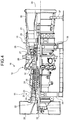
- FIG. 4 is a schematic configuration diagram of the gas turbine according to the present embodiment.
- a gas turbine 10 As illustrated in FIG. 4 , a gas turbine 10 according to the present embodiment includes a compressor 11, a combustor 12, and a turbine 13. A generator, which is not illustrated, is coaxially coupled to the gas turbine 10 and can generate electricity.
- the compressor 11 has an air intake port 20 through which air is taken in.
- a compressor casing 21 an inlet guide vane (IGV) 22 is disposed, and a plurality of compressor vanes 23 and compressor blades 24 are alternately disposed in the longitudinal direction (axial direction of a rotor 32, which will be described later).
- a bleed air chamber 25 is provided outside the compressor casing 21.
- the combustor 12 supplies fuel to compressed air compressed by the compressor 11 and ignites the fuel and the compressed air, thereby performing combustion.
- the turbine 13 includes a plurality of turbine vanes 27 and turbine blades 28 alternately disposed in the longitudinal direction (axial direction of the rotor 32, which will be described later) in a turbine casing 26.
- a flue gas chamber 30 is provided downstream of the turbine casing 26 with a flue gas casing 29 provided therebetween.
- the flue gas chamber 30 includes a flue gas diffuser 31 connected to the turbine 13.
- the rotor (rotating shaft) 32 is provided penetrating the center of the compressor 11, the combustor 12, the turbine 13, and the flue gas chamber 30.
- the end of the rotor 32 on the compressor 11 side is rotatably supported by a bearing 33, and the end thereof on the flue gas chamber 30 side is rotatably supported by a bearing 34.
- a plurality of disks provided with the respective compressor blades 24 are stacked and fixed on the rotor 32.
- a plurality of disks provided with the respective turbine blades 28 are stacked and fixed on the rotor 32.
- the end of the rotor 32 on the flue gas chamber 30 side is coupled to a drive shaft of the generator, which is not illustrated.
- the compressor casing 21 of the compressor 11 is supported by a leg 35
- the turbine casing 26 of the turbine 13 is supported by a leg 36
- the flue gas chamber 30 is supported by a leg 37.
- Air taken in from the air intake port 20 of the compressor 11 passes by the IGV 22, the compressor vanes 23, and compressor blades 24 and is compressed, thereby becoming high-temperature and high-pressure compressed air.
- the combustor 12 supplies predetermined fuel to the compressed air and performs combustion.
- the high-temperature and high-pressure combustion gas serving as working fluid generated by the combustor 12 passes by the turbine vanes 27 and the turbine blades 28 of the turbine 13, thereby driving and rotating the rotor 32.
- the generator coupled to the rotor 32 is driven.
- the combustion gas that drives the turbine 13 is released to the atmosphere as a flue gas.
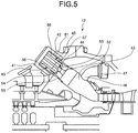
- FIG. 5 is a schematic of the gas turbine combustor.
- FIG. 6 is a schematic of a principal part of the gas turbine combustor.
- FIG. 7 is a sectional view along line VII-VII of FIG. 6 .
- an inner cylinder 42 is supported in an external cylinder 41 with a predetermined gap interposed therebetween.
- a transition piece 43 is coupled to an end of the inner cylinder 42.
- the external cylinder 41, the inner cylinder 42, and the transition piece 43 constitute a combustor casing.
- the inner cylinder 42 includes a pilot combustion burner 44 and a plurality of main combustion burners 45.
- the pilot combustion burner 44 is positioned at the center of the inside of the inner cylinder 42.
- the main combustion burners 45 are disposed surrounding the pilot combustion burner 44 along the circumferential direction on the inner peripheral surface of the inner cylinder 42.
- the transition piece 43 is coupled to a bypass pipe 46.
- the bypass pipe 46 is provided with a bypass valve 47.
- the base end of the inner cylinder 42 is attached to the base end of the external cylinder 41, thereby defining an air passage 51 therebetween.
- the pilot combustion burner 44 is positioned at the center of the inside thereof, and the main combustion burners 45 are disposed around the pilot combustion burner 44.
- the pilot combustion burner 44 includes a pilot cone 52, a pilot nozzle (first fuel injecting unit) 53, and a swirler vane 54.
- the pilot cone 52 is supported by the inner cylinder 42.
- the pilot nozzle 53 is disposed in the pilot cone 52.
- the swirler vane 54 is provided on the outer periphery of the pilot nozzle 53.
- the main combustion burners 45 each include a burner cylinder 55, a main nozzle (first fuel injecting unit) 56, and a swirler vane 57.
- the main nozzle 56 is disposed in the burner cylinder 55.
- the swirler vane 57 is provided on the outer periphery of the main nozzle 56.
- the air passage 51 having a ring shape is formed between the external cylinder 41 and the inner cylinder 42.
- a plurality of pegs (fuel injecting unit) 58 are provided in the air passage 51. As illustrated in FIG. 7 , base ends of the pegs 58 are fixed to the external cylinder 41, and distal ends thereof extend toward the inner cylinder 42. The pegs 58 are disposed at predetermined intervals in the circumferential direction of the external cylinder 41.
- the external cylinder 41 has a pilot fuel port 61, a main fuel port 62, and a top hat fuel port 63.
- the pilot fuel port 61, the main fuel port 62, and the top hat fuel port 63 are connected to the pilot nozzle 53, the main nozzles 56, and the pegs 58, respectively.
- a pilot fuel line, which is not illustrated, is coupled to the pilot fuel port 61.
- a main fuel line, which is not illustrated, is coupled to each main fuel port 62.
- a top hat fuel line, which is not illustrated, is coupled to each top hat fuel port 63.
- fuel F is injected from the pegs 58 to the compressed air to generate a mixture.
- the mixture flows into the inner cylinder 42.
- the mixture flowing into the inner cylinder 42 is mixed with the fuel F injected from the main combustion burners 45 to be a swirling flow of a pre-mixture.
- the mixture is also mixed with the fuel F injected from the pilot combustion burner 44 and ignited and burned, which is not illustrated.
- the mixture is turned into a combustion gas, and the combustion gas is injected into the inner cylinder 42. At this time, part of the combustion gas is injected into the inner cylinder 42 in a manner diffusing around with a flame.
- the pre-mixture flowing into the inner cylinder 42 from the main combustion burners 45 is ignited and combusted.
- a diffusion flame generated by the pilot fuel F injected from the pilot combustion burner 44 can perform flame holding for stable combustion of lean premixed fuel F supplied from the main combustion burners 45.
- FIG. 1 is a sectional view along line I-I of FIG. 7 and illustrates an attachment state of the peg in the gas turbine combustor according to the present embodiment.
- FIG. 2 is a schematic for explaining an attachment angle of the peg.
- the peg 58 is disposed at a curve communicating with the inner cylinder 42 downstream in the air passage 51.
- the base end of the peg 58 is supported by the curved inner surface of the external cylinder 41, and the distal end thereof extends toward the inner cylinder 42.
- the peg 58 has a cylindrical shape and has a fuel passage, which is not illustrated, inside thereof.
- One end of the fuel passage communicates with a supply hole 63a connected to the top hat fuel port 63, and the other end thereof communicates with a plurality of injection holes 58a opening to the outside of the peg 58.
- the inner surface of the external cylinder 41 defining the air passage 51 has a first linear portion 41a, a second linear portion 41c, and a curve 41b.
- the first linear portion 41a extends in the axial direction of the external cylinder 41.
- the second linear portion 41c extends in a direction (radial direction of the external cylinder 41) orthogonal to the axial direction of the external cylinder 41.
- the curve 41b connects the first linear portion 41a and the second linear portion 41c.
- the extension of the first linear portion 41a and the extension of the second linear portion 41c intersect at right angles (90 degrees) at the intersection of lengths L1 and L2, respectively.
- the base end of the peg 58 is fixed to the curve 41b, that is, a range of the length L1 extending along the first linear portion 41a and the length L2 extending along the second linear portion 41c.
- the peg 58 is disposed with its center line O in the longitudinal direction inclined to the downstream side in the flow direction of compressed air A flowing through the air passage 51 at a predetermined angle ⁇ with respect to a perpendicular P orthogonal to a tangent T to the inner surface of the curve 41b of the external cylinder 41.
- the inclination angle ⁇ is preferably from 10 degrees to 40 degrees and is most preferably approximately 30 degrees.
- the base end of the peg 58 is supported closer to the downstream side in the flow direction of the compressed air A flowing through the air passage 51 than the intersection of the extensions of the first linear portion 41a and the second linear portion 41c.
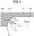
- FIG. 3 is a sectional view of a modification of the peg according to the present embodiment.
- a peg 71 is disposed at the curve 41b in the external cylinder 41 defining the air passage 51 and extends toward the inner cylinder 42.
- the peg 71 has a cylindrical shape and has a fuel passage, which is not illustrated, inside thereof. One end of the fuel passage communicates with the supply hole 63a connected to the top hat fuel port 63, and the other end thereof communicates with a plurality of injection holes 71a opening to the outside of the peg 71.
- the peg 71 has a spherical portion 71b having a spherical shape on the distal end.
- the pegs 58 and 71 do not necessarily have the shape described above.
- the pegs 58 and 71 may have a polygonal columnar shape or an elliptic cylindrical shape or be tapered, thickened toward the end, or stepped, for example. While the pegs 58 and 71 are disposed with their center line O in the longitudinal direction inclined to the downstream side in the flow direction of the compressed air A with respect to the perpendicular P, they may be disposed with their center line O in the longitudinal direction inclined to the upstream side in the flow direction of the compressed air A with respect to the perpendicular P.
- the fuel F is injected from the pegs 58 and 71 to the compressed air A to generate a mixture.
- the mixture flows into the inner cylinder 42 and is mixed with the fuel F injected from the pilot nozzle 53 and the main nozzles 56.
- the pegs 58 and 71 are inclined to the downstream side in the flow direction of the compressed air A in the air passage 51. This structure can suppress separation of the flow around a second fuel injecting unit. As a result, the number of areas where the flow of the compressed air A is slow downstream of the pegs 58 and 71 is reduced, thereby suppressing flashback of a flame from the inner cylinder 42.
- the gas turbine combustor includes the external cylinder 41, the inner cylinder 42, the pilot nozzle 53, the main nozzles 56, the air passage 51, and the pegs 58 and 71.
- the pilot nozzle 53 and the main nozzles 56 are disposed in the inner cylinder 42.
- the air passage 51 is provided between the external cylinder 41 and the inner cylinder 42.
- the pegs 58 and 71 are disposed in the air passage 51.
- the pegs 58 and 71 are disposed at the curve 41b communicating with the inner cylinder 42 downstream in the air passage 51.
- the base end of the pegs 58 and 71 is supported by the inner surface of the curve 41b, and the distal end thereof extends toward the inner cylinder 42.
- the pegs 58 and 71 are disposed with their center line O in the longitudinal direction inclined to the downstream side (or upstream side) in the flow direction of the compressed air A flowing through the air passage 51 at the predetermined angle ⁇ with respect to the perpendicular P orthogonal to the tangent T to the curved surface of the external cylinder 41.
- This structure can suppress separation of the flow around the pegs 58 and 71. Consequently, the present embodiment can reduce the number of areas where the flow of the compressed air A is slow downstream of the pegs 58 and 71, thereby suppressing flashback of a flame.
- the pegs 58 and 71 are inclined to the downstream side in the flow direction of the compressed air A within a range from 10 degrees to 30 degrees. With this structure, the pegs 58 and 71 are less likely to be resistance to the flow of the compressed air A. Consequently, the present embodiment can reduce the number of areas where the flow of the compressed air A is slow downstream of the pegs 58 and 71.
- the inner surface of the external cylinder 41 defining the air passage 51 has the first linear portion 41a, the second linear portion 41c, and the curve 41b.
- the first linear portion 41a extends in the axial direction of the external cylinder 41.
- the second linear portion 41c extends in a direction orthogonal to the axial direction of the external cylinder 41.
- the curve 41b connects the first linear portion 41a and the second linear portion 41c.
- the base end of the pegs 58 and 71 is supported closer to the downstream side in the flow direction of the compressed air A flowing through the air passage 51 than the intersection of the extensions of the first linear portion 41a and the second linear portion 41c. Consequently, the present embodiment can further suppress flashback of a flame. Furthermore, the change in the fuel injection position can improve the combustibility.
- the peg 71 has a cylindrical shape and has the spherical portion 71b on the distal end. With this structure, the peg 71 is less likely to be resistance to the flow of the compressed air A. Consequently, the present embodiment can suppress separation of the compressed air A caused by the peg 71 and reduce the number of areas having slow flow velocity in the wake of the second fuel injecting unit.
- the gas turbine according to the present embodiment includes the compressor 11, the combustor 12, and the turbine 13.
- the compressor 11 compresses air.
- the combustor 12 mixes the compressed air A compressed by the compressor 11 with the fuel F and performs combustion.
- the turbine 13 obtains rotational power from the combustion gas generated by the combustor 12.
- the combustor 12 includes the pegs 58 and 71 disposed at the curve 41b of the air passage 51.
- the pegs 58 and 71 are inclined to the downstream side (or upstream side) in the flow direction of the compressed air A flowing through the air passage 51 at the predetermined angle ⁇ .
- the present embodiment can suppress separation of the flow around the pegs 58 and 71. As a result, the amount of compressed air flowing around the pegs 58 and 71 is reduced, thereby reducing the number of areas where the flow of the compressed air A is slow downstream of the pegs 58 and 71. Consequently, the present embodiment can suppress flashback of a flame.
- pegs 58 and 71 are disposed at the curve 41b communicating with the inner cylinder 42 downstream in the air passage 51, they may be disposed at the linear portion 41a or 41b instead of the curve 41b.
Landscapes
- Engineering & Computer Science (AREA)
- Chemical & Material Sciences (AREA)
- Combustion & Propulsion (AREA)
- Mechanical Engineering (AREA)
- General Engineering & Computer Science (AREA)
- Pressure-Spray And Ultrasonic-Wave- Spray Burners (AREA)
Abstract
Description
- The present invention relates to a gas turbine combustor used for a gas turbine that supplies fuel to compressed high-temperature and high-pressure air to perform combustion and supplies a generated combustion gas to a turbine to obtain rotational power, and to the gas turbine including the gas turbine combustor.
- A typical gas turbine includes a compressor, a combustor, and a turbine. Air taken in through an air intake port is compressed by the compressor to be high-temperature and high-pressure compressed air. The combustor supplies fuel to the compressed air and performs combustion, thereby obtaining a high-temperature and high-pressure combustion gas (working fluid). The gas turbine drives the turbine with the combustion gas, thereby driving a generator coupled to the turbine.
- In the combustor of the gas turbine having the configuration described above, an inner cylinder is supported in an external cylinder, and a transition piece is coupled to an end of the inner cylinder. The external cylinder, the inner cylinder, and the transition piece constitute a casing. The inner cylinder is provided with a pilot nozzle and a plurality of main fuel nozzles. The external cylinder is provided with a plurality of top hat nozzles on the inner peripheral surface. When an air flow of the compressed air comes into the inner cylinder through an air passage, the fuel is injected from the top hat nozzles. The air-fuel mixture is mixed with the fuel injected from the main fuel nozzles in the inner cylinder to be a swirling flow of a pre-mixture flowing into the transition piece. The air-fuel mixture is also mixed with the fuel injected from the pilot nozzle and ignited and burned. As a result, the air-fuel mixture is turned into a combustion gas, and the combustion gas is injected into the transition piece. As a result, the pre-mixture flowing into the transition piece from the main fuel nozzles is ignited and combusted.
- Various gas turbine combustors have been developed, including the combustor described in Patent Literature 1, for example.
- Patent Literature 1: Japanese Patent Application Laid-open No.
2005-233574 - Before the compressed air flows into the inner cylinder, the gas turbine combustor described above mixes in advance the fuel injected from the top hat nozzles with the compressed air flowing through the air passage. Consequently, the gas turbine combustor can mix the fuel and the air for combustion in the mixture more uniformly in the inner cylinder. The top hat nozzles, however, protrude perpendicularly to the flow of the compressed air. This structure causes separation of the flow around the top hat nozzles, thereby generating areas where the flow of the compressed air is slow downstream. As a result, the flame generated in the inner cylinder and the transition piece may possibly flash back, thereby damaging the top hat nozzles.
- To address the disadvantages described above, an object of the present invention is to provide a gas turbine combustor and a gas turbine that suppresses flashback of a flame.
- To achieve the object described above, a gas turbine combustor of the present invention is a gas turbine combustor that includes an external cylinder having a tubular shape, an inner cylinder disposed in the external cylinder, a first fuel injecting unit disposed in the inner cylinder, an air passage provided between the external cylinder and the inner cylinder to cause compressed air to flow into the inner cylinder, and a second fuel injecting unit disposed in the air passage. The second fuel injecting unit is disposed at a curve communicating with the inner cylinder downstream in the air passage. The second fuel injecting unit has a base end supported by a curved inner surface of the external cylinder and a distal end extending toward the inner cylinder. The second fuel injecting unit is disposed with a center line in a longitudinal direction inclined to a downstream side or an upstream side in a flow direction of the compressed air flowing through the air passage at a predetermined angle with respect to a perpendicular orthogonal to a tangent to the curved inner surface of the external cylinder.
- If the compressed air flows into the air passage, fuel is injected from the second fuel injecting unit to the compressed air to generate a mixture. The mixture flows into the inner cylinder. The fuel is injected from the first fuel injecting unit to the mixture to generate a pre-mixture. The second fuel injecting unit is inclined to the downstream side or the upstream side in the flow direction of the compressed air in the air passage. This structure can suppress separation of the flow around the second fuel injecting unit. Consequently, the present invention can reduce the number of areas where the flow of the compressed air is slow downstream of the second fuel injecting unit, thereby suppressing flashback of a flame.
- In the gas turbine combustor, the second fuel injecting unit is disposed with the center line in the longitudinal direction inclined to the downstream side in the flow direction of the compressed air flowing through the air passage with respect to the perpendicular within a range from 10 degrees to 30 degrees.
- The second fuel injecting unit is inclined to the downstream side in the flow direction of the compressed air within a range from 10 degrees to 30 degrees. With this structure, the second fuel injecting unit is less likely to be resistance to the flow of the compressed air. Consequently, the present invention can reduce the number of areas where the flow of the compressed air is slow downstream of the second fuel injecting unit.
- In the gas turbine combustor, an inner surface of the external cylinder defining the air passage has a first linear portion extending in an axial direction of the external cylinder, a second linear portion extending in a direction orthogonal to the axial direction of the external cylinder, and a curve connecting the first linear portion and the second linear portion, and the base end of the second fuel injecting unit is supported closer to the downstream side in the flow direction of the compressed air flowing through the air passage than an intersection of extensions of the first linear portion and the second linear portion.
- Consequently, the present invention can further suppress flashback of a flame. Furthermore, the change in the fuel injection position can improve the combustion stability.
- In the gas turbine combustor, the second fuel injecting unit has a cylindrical shape and has a spherical shape on the distal end.
- The second fuel injecting unit has a cylindrical shape and has a spherical shape on the distal end. Consequently, the present invention can suppress separation of the compressed air caused by the second fuel injecting unit and reduce the number of areas having slow flow velocity in the wake of the second fuel injecting unit.
- A gas turbine of the present invention includes a compressor configured to compress air, a combustor configured to mix compressed air compressed by the compressor with fuel to perform combustion, and a turbine configured to obtain rotational power from a combustion gas generated by the combustor. As the combustor, the gas turbine combustor is used.
- In the combustor, the second fuel injecting unit disposed in the air passage provided between the external cylinder and the inner cylinder is inclined to the downstream side or the upstream side in the flow direction of the compressed air at the predetermined angle. This structure can suppress separation of the flow around the second fuel injecting unit. Consequently, the present invention can reduce the number of areas where the flow of the compressed air is slow downstream of the second fuel injecting unit, thereby suppressing flashback of a flame. Advantageous Effects of Invention
- In the gas turbine combustor and the gas turbine according to the present invention, the second fuel injecting unit disposed in the air passage provided between the external cylinder and the inner cylinder is inclined to the downstream side or the upstream side in the flow direction of the compressed air at the predetermined angle. Consequently, the present invention can reduce the number of areas where the flow of the compressed air is slow downstream of the second fuel injecting unit, thereby suppressing flashback of a flame.
-
-
FIG. 1 is a sectional view along line I-I ofFIG. 7 and illustrates an attachment state of a peg in a gas turbine combustor according to the present embodiment. -
FIG. 2 is a schematic for explaining an attachment angle of the peg. -
FIG. 3 is a sectional view of a modification of the peg according to the present embodiment. -
FIG. 4 is a schematic configuration diagram of a gas turbine according to the present embodiment. -
FIG. 5 is a schematic of the gas turbine combustor.FIG. 6 is a schematic of a principal part of the gas turbine combustor. -
FIG. 7 is a sectional view along line VII-VII ofFIG. 6 . - Exemplary embodiments of a gas turbine combustor and a gas turbine according to the present invention are described below in greater detail with reference to the accompanying drawings. The embodiments are not intended to limit the present invention. If there are a plurality of embodiments, the present invention includes a combination of the embodiments.
-
FIG. 4 is a schematic configuration diagram of the gas turbine according to the present embodiment. - As illustrated in
FIG. 4 , agas turbine 10 according to the present embodiment includes acompressor 11, acombustor 12, and aturbine 13. A generator, which is not illustrated, is coaxially coupled to thegas turbine 10 and can generate electricity. - The
compressor 11 has anair intake port 20 through which air is taken in. In acompressor casing 21, an inlet guide vane (IGV) 22 is disposed, and a plurality ofcompressor vanes 23 andcompressor blades 24 are alternately disposed in the longitudinal direction (axial direction of arotor 32, which will be described later). Ableed air chamber 25 is provided outside thecompressor casing 21. Thecombustor 12 supplies fuel to compressed air compressed by thecompressor 11 and ignites the fuel and the compressed air, thereby performing combustion. Theturbine 13 includes a plurality ofturbine vanes 27 andturbine blades 28 alternately disposed in the longitudinal direction (axial direction of therotor 32, which will be described later) in aturbine casing 26. Aflue gas chamber 30 is provided downstream of theturbine casing 26 with aflue gas casing 29 provided therebetween. Theflue gas chamber 30 includes aflue gas diffuser 31 connected to theturbine 13. - The rotor (rotating shaft) 32 is provided penetrating the center of the
compressor 11, thecombustor 12, theturbine 13, and theflue gas chamber 30. The end of therotor 32 on thecompressor 11 side is rotatably supported by abearing 33, and the end thereof on theflue gas chamber 30 side is rotatably supported by abearing 34. In thecompressor 11, a plurality of disks provided with therespective compressor blades 24 are stacked and fixed on therotor 32. In theturbine 13, a plurality of disks provided with therespective turbine blades 28 are stacked and fixed on therotor 32. The end of therotor 32 on theflue gas chamber 30 side is coupled to a drive shaft of the generator, which is not illustrated. - In the
gas turbine 10, thecompressor casing 21 of thecompressor 11 is supported by aleg 35, theturbine casing 26 of theturbine 13 is supported by aleg 36, and theflue gas chamber 30 is supported by aleg 37. - Air taken in from the
air intake port 20 of thecompressor 11 passes by theIGV 22, thecompressor vanes 23, andcompressor blades 24 and is compressed, thereby becoming high-temperature and high-pressure compressed air. Thecombustor 12 supplies predetermined fuel to the compressed air and performs combustion. The high-temperature and high-pressure combustion gas serving as working fluid generated by the combustor 12 passes by theturbine vanes 27 and theturbine blades 28 of theturbine 13, thereby driving and rotating therotor 32. As a result, the generator coupled to therotor 32 is driven. The combustion gas that drives theturbine 13 is released to the atmosphere as a flue gas. - The following describes the combustor (gas turbine combustor) according to the present embodiment in greater detail.
FIG. 5 is a schematic of the gas turbine combustor.FIG. 6 is a schematic of a principal part of the gas turbine combustor.FIG. 7 is a sectional view along line VII-VII ofFIG. 6 . - In the
combustor 12, as illustrated inFIG. 5 , aninner cylinder 42 is supported in anexternal cylinder 41 with a predetermined gap interposed therebetween. Atransition piece 43 is coupled to an end of theinner cylinder 42. Theexternal cylinder 41, theinner cylinder 42, and thetransition piece 43 constitute a combustor casing. Theinner cylinder 42 includes apilot combustion burner 44 and a plurality ofmain combustion burners 45. Thepilot combustion burner 44 is positioned at the center of the inside of theinner cylinder 42. Themain combustion burners 45 are disposed surrounding thepilot combustion burner 44 along the circumferential direction on the inner peripheral surface of theinner cylinder 42. Thetransition piece 43 is coupled to abypass pipe 46. Thebypass pipe 46 is provided with abypass valve 47. - Specifically, as illustrated in
FIG. 6 , the base end of theinner cylinder 42 is attached to the base end of theexternal cylinder 41, thereby defining anair passage 51 therebetween. In theinner cylinder 42, thepilot combustion burner 44 is positioned at the center of the inside thereof, and themain combustion burners 45 are disposed around thepilot combustion burner 44. Thepilot combustion burner 44 includes apilot cone 52, a pilot nozzle (first fuel injecting unit) 53, and aswirler vane 54. Thepilot cone 52 is supported by theinner cylinder 42. Thepilot nozzle 53 is disposed in thepilot cone 52. Theswirler vane 54 is provided on the outer periphery of thepilot nozzle 53. Themain combustion burners 45 each include aburner cylinder 55, a main nozzle (first fuel injecting unit) 56, and aswirler vane 57. Themain nozzle 56 is disposed in theburner cylinder 55. Theswirler vane 57 is provided on the outer periphery of themain nozzle 56. - The
air passage 51 having a ring shape is formed between theexternal cylinder 41 and theinner cylinder 42. A plurality of pegs (fuel injecting unit) 58 are provided in theair passage 51. As illustrated inFIG. 7 , base ends of thepegs 58 are fixed to theexternal cylinder 41, and distal ends thereof extend toward theinner cylinder 42. Thepegs 58 are disposed at predetermined intervals in the circumferential direction of theexternal cylinder 41. - As illustrated in
FIG. 6 , theexternal cylinder 41 has apilot fuel port 61, amain fuel port 62, and a tophat fuel port 63. Thepilot fuel port 61, themain fuel port 62, and the tophat fuel port 63 are connected to thepilot nozzle 53, themain nozzles 56, and thepegs 58, respectively. A pilot fuel line, which is not illustrated, is coupled to thepilot fuel port 61. A main fuel line, which is not illustrated, is coupled to eachmain fuel port 62. A top hat fuel line, which is not illustrated, is coupled to each tophat fuel port 63. - If an air flow of high-temperature and high-pressure compressed air comes into the
air passage 51, fuel F is injected from thepegs 58 to the compressed air to generate a mixture. The mixture flows into theinner cylinder 42. The mixture flowing into theinner cylinder 42 is mixed with the fuel F injected from themain combustion burners 45 to be a swirling flow of a pre-mixture. The mixture is also mixed with the fuel F injected from thepilot combustion burner 44 and ignited and burned, which is not illustrated. As a result, the mixture is turned into a combustion gas, and the combustion gas is injected into theinner cylinder 42. At this time, part of the combustion gas is injected into theinner cylinder 42 in a manner diffusing around with a flame. As a result, the pre-mixture flowing into theinner cylinder 42 from themain combustion burners 45 is ignited and combusted. In other words, a diffusion flame generated by the pilot fuel F injected from thepilot combustion burner 44 can perform flame holding for stable combustion of lean premixed fuel F supplied from themain combustion burners 45. - The following describes the
peg 58 in greater detail.FIG. 1 is a sectional view along line I-I ofFIG. 7 and illustrates an attachment state of the peg in the gas turbine combustor according to the present embodiment.FIG. 2 is a schematic for explaining an attachment angle of the peg. - As illustrated in
FIG. 1 , thepeg 58 is disposed at a curve communicating with theinner cylinder 42 downstream in theair passage 51. The base end of thepeg 58 is supported by the curved inner surface of theexternal cylinder 41, and the distal end thereof extends toward theinner cylinder 42. Thepeg 58 has a cylindrical shape and has a fuel passage, which is not illustrated, inside thereof. One end of the fuel passage communicates with asupply hole 63a connected to the tophat fuel port 63, and the other end thereof communicates with a plurality ofinjection holes 58a opening to the outside of thepeg 58. - As illustrated in
FIG. 2 , the inner surface of theexternal cylinder 41 defining theair passage 51 has a firstlinear portion 41a, a secondlinear portion 41c, and acurve 41b. The firstlinear portion 41a extends in the axial direction of theexternal cylinder 41. The secondlinear portion 41c extends in a direction (radial direction of the external cylinder 41) orthogonal to the axial direction of theexternal cylinder 41. Thecurve 41b connects the firstlinear portion 41a and the secondlinear portion 41c. In other words, the extension of the firstlinear portion 41a and the extension of the secondlinear portion 41c intersect at right angles (90 degrees) at the intersection of lengths L1 and L2, respectively. The base end of thepeg 58 is fixed to thecurve 41b, that is, a range of the length L1 extending along the firstlinear portion 41a and the length L2 extending along the secondlinear portion 41c. - The
peg 58 is disposed with its center line O in the longitudinal direction inclined to the downstream side in the flow direction of compressed air A flowing through theair passage 51 at a predetermined angle θ with respect to a perpendicular P orthogonal to a tangent T to the inner surface of thecurve 41b of theexternal cylinder 41. The inclination angle θ is preferably from 10 degrees to 40 degrees and is most preferably approximately 30 degrees. - The base end of the
peg 58 is supported closer to the downstream side in the flow direction of the compressed air A flowing through theair passage 51 than the intersection of the extensions of the firstlinear portion 41a and the secondlinear portion 41c. - The
peg 58 does not necessarily have the shape described above.FIG. 3 is a sectional view of a modification of the peg according to the present embodiment. - As illustrated in
FIG. 3 , apeg 71 is disposed at thecurve 41b in theexternal cylinder 41 defining theair passage 51 and extends toward theinner cylinder 42. Thepeg 71 has a cylindrical shape and has a fuel passage, which is not illustrated, inside thereof. One end of the fuel passage communicates with thesupply hole 63a connected to the tophat fuel port 63, and the other end thereof communicates with a plurality ofinjection holes 71a opening to the outside of thepeg 71. Thepeg 71 has aspherical portion 71b having a spherical shape on the distal end. - The
pegs pegs pegs - If the compressed air A flows into the
air passage 51, the fuel F is injected from thepegs inner cylinder 42 and is mixed with the fuel F injected from thepilot nozzle 53 and themain nozzles 56. Thepegs air passage 51. This structure can suppress separation of the flow around a second fuel injecting unit. As a result, the number of areas where the flow of the compressed air A is slow downstream of thepegs inner cylinder 42. - As described above, the gas turbine combustor according to the present embodiment includes the
external cylinder 41, theinner cylinder 42, thepilot nozzle 53, themain nozzles 56, theair passage 51, and thepegs pilot nozzle 53 and themain nozzles 56 are disposed in theinner cylinder 42. Theair passage 51 is provided between theexternal cylinder 41 and theinner cylinder 42. Thepegs air passage 51. Thepegs curve 41b communicating with theinner cylinder 42 downstream in theair passage 51. The base end of thepegs curve 41b, and the distal end thereof extends toward theinner cylinder 42. Thepegs air passage 51 at the predetermined angle θ with respect to the perpendicular P orthogonal to the tangent T to the curved surface of theexternal cylinder 41. - This structure can suppress separation of the flow around the
pegs pegs - In the gas turbine combustor according to the present embodiment, the
pegs pegs pegs - In the gas turbine combustor according to the present embodiment, the inner surface of the
external cylinder 41 defining theair passage 51 has the firstlinear portion 41a, the secondlinear portion 41c, and thecurve 41b. The firstlinear portion 41a extends in the axial direction of theexternal cylinder 41. The secondlinear portion 41c extends in a direction orthogonal to the axial direction of theexternal cylinder 41. Thecurve 41b connects the firstlinear portion 41a and the secondlinear portion 41c. The base end of thepegs air passage 51 than the intersection of the extensions of the firstlinear portion 41a and the secondlinear portion 41c. Consequently, the present embodiment can further suppress flashback of a flame. Furthermore, the change in the fuel injection position can improve the combustibility. - In the gas turbine combustor according to the present embodiment, the
peg 71 has a cylindrical shape and has thespherical portion 71b on the distal end. With this structure, thepeg 71 is less likely to be resistance to the flow of the compressed air A. Consequently, the present embodiment can suppress separation of the compressed air A caused by thepeg 71 and reduce the number of areas having slow flow velocity in the wake of the second fuel injecting unit. - The gas turbine according to the present embodiment includes the
compressor 11, thecombustor 12, and theturbine 13. Thecompressor 11 compresses air. Thecombustor 12 mixes the compressed air A compressed by thecompressor 11 with the fuel F and performs combustion. Theturbine 13 obtains rotational power from the combustion gas generated by thecombustor 12. Thecombustor 12 includes thepegs curve 41b of theair passage 51. Thepegs air passage 51 at the predetermined angle θ. - With this structure, the present embodiment can suppress separation of the flow around the
pegs pegs pegs - While the
pegs curve 41b communicating with theinner cylinder 42 downstream in theair passage 51, they may be disposed at thelinear portion curve 41b. -
- 10
- Gas turbine
- 11
- Compressor
- 12
- Combustor
- 13
- Turbine
- 41
- External cylinder
- 41a
- First linear portion
- 41b
- Curve
- 41c
- Second linear portion
- 42
- Inner cylinder
- 43
- Transition piece
- 44
- Pilot combustion burner
- 45
- Main combustion burner
- 51
- Air passage
- 53
- Pilot nozzle (first fuel injecting unit)
- 56
- Main nozzle (first fuel injecting unit)
- 58, 71
- Peg (second fuel injecting unit)
- 58a, 71a
- Injection hole
- 71b
- Spherical portion
- A
- Compressed air
- F
- Fuel
- L1, L2
- Length
- O
- Center line
- P
- Perpendicular
- T
- Tangent
- θ
- Inclination angle
Claims (5)
- A gas turbine combustor comprising:an external cylinder having a tubular shape;an inner cylinder disposed in the external cylinder;a first fuel injecting unit disposed in the inner cylinder;an air passage provided between the external cylinder and the inner cylinder to cause compressed air to flow into the inner cylinder; anda second fuel injecting unit disposed in the air passage, whereinthe second fuel injecting unit is disposed at a curve communicating with the inner cylinder downstream in the air passage, the second fuel injecting unit having a base end supported by a curved inner surface of the external cylinder and a distal end extending toward the inner cylinder, andthe second fuel injecting unit is disposed with a center line in a longitudinal direction inclined to a downstream side or an upstream side in a flow direction of the compressed air flowing through the air passage at a predetermined angle with respect to a perpendicular orthogonal to a tangent to the curved inner surface of the external cylinder.
- The gas turbine combustor according to claim 1, wherein the second fuel injecting unit is disposed with the center line in the longitudinal direction inclined to the downstream side in the flow direction of the compressed air flowing through the air passage with respect to the perpendicular within a range from 10 degrees to 30 degrees.
- The gas turbine combustor according to claim 1 or 2, wherein an inner surface of the external cylinder defining the air passage has a first linear portion extending in an axial direction of the external cylinder, a second linear portion extending in a direction orthogonal to the axial direction of the external cylinder, and a curve connecting the first linear portion and the second linear portion, and the base end of the second fuel injecting unit is supported closer to the downstream side in the flow direction of the compressed air flowing through the air passage than an intersection of extensions of the first linear portion and the second linear portion.
- The gas turbine combustor according to any one of claims 1 to 3, wherein the second fuel injecting unit has a cylindrical shape and has a spherical shape on the distal end.
- A gas turbine comprising:a compressor configured to compress air;a combustor configured to mix compressed air compressed by the compressor with fuel to perform combustion; anda turbine configured to obtain rotational power from a combustion gas generated by the combustor, whereinas the combustor, the gas turbine combustor according to any one of claims 1 to 4 is used.
Applications Claiming Priority (2)
| Application Number | Priority Date | Filing Date | Title |
|---|---|---|---|
| JP2016043589A JP6647924B2 (en) | 2016-03-07 | 2016-03-07 | Gas turbine combustor and gas turbine |
| PCT/JP2017/008996 WO2017154900A1 (en) | 2016-03-07 | 2017-03-07 | Gas turbine combustor and gas turbine |
Publications (2)
| Publication Number | Publication Date |
|---|---|
| EP3428536A1 true EP3428536A1 (en) | 2019-01-16 |
| EP3428536A4 EP3428536A4 (en) | 2019-07-31 |
Family
ID=59790312
Family Applications (1)
| Application Number | Title | Priority Date | Filing Date |
|---|---|---|---|
| EP17763240.3A Withdrawn EP3428536A4 (en) | 2016-03-07 | 2017-03-07 | Gas turbine combustor and gas turbine |
Country Status (7)
| Country | Link |
|---|---|
| US (1) | US20190086093A1 (en) |
| EP (1) | EP3428536A4 (en) |
| JP (1) | JP6647924B2 (en) |
| KR (1) | KR20180110070A (en) |
| CN (1) | CN108700300A (en) |
| TW (1) | TWI622735B (en) |
| WO (1) | WO2017154900A1 (en) |
Families Citing this family (8)
| Publication number | Priority date | Publication date | Assignee | Title |
|---|---|---|---|---|
| KR101889542B1 (en) * | 2017-04-18 | 2018-08-17 | 두산중공업 주식회사 | Combustor Nozzle Assembly And Gas Turbine Having The Same |
| JP6546334B1 (en) * | 2018-12-03 | 2019-07-17 | 三菱日立パワーシステムズ株式会社 | Gas turbine combustor and gas turbine equipped with the same |
| JP7191723B2 (en) * | 2019-02-27 | 2022-12-19 | 三菱重工業株式会社 | gas turbine combustor and gas turbine |
| JP7096182B2 (en) | 2019-02-27 | 2022-07-05 | 三菱重工業株式会社 | Gas turbine combustor and gas turbine |
| JP7446077B2 (en) * | 2019-10-04 | 2024-03-08 | 三菱重工業株式会社 | Gas turbine combustor, gas turbine and oil fuel combustion method |
| JP7393262B2 (en) * | 2020-03-23 | 2023-12-06 | 三菱重工業株式会社 | Combustor and gas turbine equipped with the same |
| JP7379265B2 (en) * | 2020-04-22 | 2023-11-14 | 三菱重工業株式会社 | Burner assembly, gas turbine combustor and gas turbine |
| US12247740B2 (en) * | 2020-06-26 | 2025-03-11 | Mitsubishi Heavy Industries, Ltd. | Fuel injector, combustor including the fuel injector, and gas turbine including the combustor |
Family Cites Families (19)
| Publication number | Priority date | Publication date | Assignee | Title |
|---|---|---|---|---|
| JPH06272862A (en) * | 1993-03-18 | 1994-09-27 | Hitachi Ltd | Method and apparatus for mixing fuel into air |
| JP3192055B2 (en) * | 1994-11-08 | 2001-07-23 | 株式会社日立製作所 | Gas turbine combustor |
| US5647215A (en) * | 1995-11-07 | 1997-07-15 | Westinghouse Electric Corporation | Gas turbine combustor with turbulence enhanced mixing fuel injectors |
| JPH09184629A (en) * | 1996-01-04 | 1997-07-15 | Hitachi Ltd | Gas turbine combustor premixer |
| US6047550A (en) * | 1996-05-02 | 2000-04-11 | General Electric Co. | Premixing dry low NOx emissions combustor with lean direct injection of gas fuel |
| JP3709671B2 (en) * | 1997-09-29 | 2005-10-26 | 株式会社日立製作所 | Gas turbine combustor |
| JP4508474B2 (en) * | 2001-06-07 | 2010-07-21 | 三菱重工業株式会社 | Combustor |
| US6786047B2 (en) * | 2002-09-17 | 2004-09-07 | Siemens Westinghouse Power Corporation | Flashback resistant pre-mix burner for a gas turbine combustor |
| JP2005233574A (en) * | 2004-02-23 | 2005-09-02 | Mitsubishi Heavy Ind Ltd | Combustor |
| JP2008025910A (en) * | 2006-07-20 | 2008-02-07 | Mitsubishi Heavy Ind Ltd | Gas turbine combustor |
| JP4918509B2 (en) * | 2008-02-15 | 2012-04-18 | 三菱重工業株式会社 | Combustor |
| WO2011018853A1 (en) * | 2009-08-13 | 2011-02-17 | 三菱重工業株式会社 | Combustor |
| US20110083440A1 (en) * | 2009-10-14 | 2011-04-14 | General Electric Company | High strength crossover manifold and method of joining |
| JP2011111964A (en) * | 2009-11-26 | 2011-06-09 | Mitsubishi Heavy Ind Ltd | Gas turbine combustor |
| JP5546432B2 (en) * | 2010-11-30 | 2014-07-09 | 株式会社日立製作所 | Gas turbine combustor and fuel supply method |
| JP5721447B2 (en) * | 2011-01-17 | 2015-05-20 | 三菱日立パワーシステムズ株式会社 | Gas turbine combustor, gas turbine equipped with the same, gas turbine plant equipped with the same, and control method therefor |
| EP2698582B1 (en) * | 2011-03-16 | 2017-11-22 | Mitsubishi Hitachi Power Systems, Ltd. | Gas turbine combustor and gas turbine |
| JP6154988B2 (en) * | 2012-01-05 | 2017-06-28 | 三菱日立パワーシステムズ株式会社 | Combustor |
| JP6004976B2 (en) * | 2013-03-21 | 2016-10-12 | 三菱重工業株式会社 | Combustor and gas turbine |
-
2016
- 2016-03-07 JP JP2016043589A patent/JP6647924B2/en active Active
-
2017
- 2017-03-07 TW TW106107417A patent/TWI622735B/en active
- 2017-03-07 KR KR1020187025757A patent/KR20180110070A/en not_active Ceased
- 2017-03-07 US US16/082,466 patent/US20190086093A1/en not_active Abandoned
- 2017-03-07 CN CN201780015643.5A patent/CN108700300A/en active Pending
- 2017-03-07 EP EP17763240.3A patent/EP3428536A4/en not_active Withdrawn
- 2017-03-07 WO PCT/JP2017/008996 patent/WO2017154900A1/en not_active Ceased
Also Published As
| Publication number | Publication date |
|---|---|
| US20190086093A1 (en) | 2019-03-21 |
| CN108700300A (en) | 2018-10-23 |
| TW201809550A (en) | 2018-03-16 |
| JP2017161109A (en) | 2017-09-14 |
| EP3428536A4 (en) | 2019-07-31 |
| JP6647924B2 (en) | 2020-02-14 |
| KR20180110070A (en) | 2018-10-08 |
| WO2017154900A1 (en) | 2017-09-14 |
| TWI622735B (en) | 2018-05-01 |
Similar Documents
| Publication | Publication Date | Title |
|---|---|---|
| US20190086093A1 (en) | Gas turbine combustor and gas turbine | |
| US8826666B2 (en) | Nozzle, and gas turbine combustor having the nozzle | |
| JP6266211B2 (en) | Combustor assembly with vortex retention cavities | |
| KR102046455B1 (en) | Fuel nozzle, combustor and gas turbine having the same | |
| CN103822228B (en) | Fuel nozzle and its assemble method | |
| JP5265585B2 (en) | Fuel nozzle for turbomachinery | |
| CN103438480A (en) | Nozzle and combustor for a gas turbine engine, and corresponding methods | |
| EP3102877B1 (en) | Combustor | |
| KR102164318B1 (en) | Co-axial dual swirler nozzle | |
| CN101368739A (en) | Method and apparatus for combustion of fuel in gas turbine engine | |
| US9989258B2 (en) | Premixed-combustion gas turbine combustor | |
| JP2017072361A (en) | Premix fuel nozzle assembly cartridge | |
| US10697639B2 (en) | Dual-fuel fuel nozzle with liquid fuel tip | |
| US11175043B2 (en) | Burner assembly, combustor, and gas turbine | |
| US10823420B2 (en) | Pilot nozzle with inline premixing | |
| CN102679400B (en) | There is the burner of prenozzle mixing cap assembly | |
| KR102070908B1 (en) | Nozzle for combustor, combustor, and gas turbine including the same | |
| JP2013148341A (en) | Fuel nozzle | |
| JP7408908B2 (en) | Combustor nozzle, combustor, and gas turbine including the same | |
| US11215364B2 (en) | Combustor, gas turbine | |
| WO2024116966A1 (en) | Method for operating gas turbine | |
| CN121184240A (en) | Gas turbine engine and its fuel nozzle assembly |
Legal Events
| Date | Code | Title | Description |
|---|---|---|---|
| STAA | Information on the status of an ep patent application or granted ep patent |
Free format text: STATUS: THE INTERNATIONAL PUBLICATION HAS BEEN MADE |
|
| PUAI | Public reference made under article 153(3) epc to a published international application that has entered the european phase |
Free format text: ORIGINAL CODE: 0009012 |
|
| STAA | Information on the status of an ep patent application or granted ep patent |
Free format text: STATUS: REQUEST FOR EXAMINATION WAS MADE |
|
| 17P | Request for examination filed |
Effective date: 20180906 |
|
| AK | Designated contracting states |
Kind code of ref document: A1 Designated state(s): AL AT BE BG CH CY CZ DE DK EE ES FI FR GB GR HR HU IE IS IT LI LT LU LV MC MK MT NL NO PL PT RO RS SE SI SK SM TR |
|
| AX | Request for extension of the european patent |
Extension state: BA ME |
|
| DAV | Request for validation of the european patent (deleted) | ||
| DAX | Request for extension of the european patent (deleted) | ||
| A4 | Supplementary search report drawn up and despatched |
Effective date: 20190627 |
|
| RIC1 | Information provided on ipc code assigned before grant |
Ipc: F23D 14/82 20060101ALI20190621BHEP Ipc: F23R 3/10 20060101ALI20190621BHEP Ipc: F23R 3/28 20060101AFI20190621BHEP Ipc: F23R 3/44 20060101ALI20190621BHEP Ipc: F23R 3/30 20060101ALI20190621BHEP Ipc: F23R 3/16 20060101ALI20190621BHEP Ipc: F23R 3/34 20060101ALI20190621BHEP |
|
| STAA | Information on the status of an ep patent application or granted ep patent |
Free format text: STATUS: THE APPLICATION HAS BEEN WITHDRAWN |
|
| 18W | Application withdrawn |
Effective date: 20200116 |