EP3428516A2 - Replaceable led light source for an led traffic signal application - Google Patents
Replaceable led light source for an led traffic signal application Download PDFInfo
- Publication number
- EP3428516A2 EP3428516A2 EP18182403.8A EP18182403A EP3428516A2 EP 3428516 A2 EP3428516 A2 EP 3428516A2 EP 18182403 A EP18182403 A EP 18182403A EP 3428516 A2 EP3428516 A2 EP 3428516A2
- Authority
- EP
- European Patent Office
- Prior art keywords
- light source
- lighting device
- optical element
- refractive optical
- light
- Prior art date
- Legal status (The legal status is an assumption and is not a legal conclusion. Google has not performed a legal analysis and makes no representation as to the accuracy of the status listed.)
- Withdrawn
Links
- 230000003287 optical effect Effects 0.000 claims abstract description 65
- 238000000034 method Methods 0.000 claims description 16
- 239000000565 sealant Substances 0.000 claims description 5
- 230000000977 initiatory effect Effects 0.000 claims description 2
- 239000000463 material Substances 0.000 description 4
- 238000010586 diagram Methods 0.000 description 2
- 230000007257 malfunction Effects 0.000 description 2
- 230000009286 beneficial effect Effects 0.000 description 1
- 230000007812 deficiency Effects 0.000 description 1
- 230000017525 heat dissipation Effects 0.000 description 1
- 238000012423 maintenance Methods 0.000 description 1
- 239000011347 resin Substances 0.000 description 1
- 229920005989 resin Polymers 0.000 description 1
- 229910052710 silicon Inorganic materials 0.000 description 1
- 239000010703 silicon Substances 0.000 description 1
Images


Classifications
-
- F—MECHANICAL ENGINEERING; LIGHTING; HEATING; WEAPONS; BLASTING
- F21—LIGHTING
- F21V—FUNCTIONAL FEATURES OR DETAILS OF LIGHTING DEVICES OR SYSTEMS THEREOF; STRUCTURAL COMBINATIONS OF LIGHTING DEVICES WITH OTHER ARTICLES, NOT OTHERWISE PROVIDED FOR
- F21V17/00—Fastening of component parts of lighting devices, e.g. shades, globes, refractors, reflectors, filters, screens, grids or protective cages
- F21V17/002—Fastening of component parts of lighting devices, e.g. shades, globes, refractors, reflectors, filters, screens, grids or protective cages with provision for interchangeability, i.e. component parts being especially adapted to be replaced by another part with the same or a different function
-
- F—MECHANICAL ENGINEERING; LIGHTING; HEATING; WEAPONS; BLASTING
- F21—LIGHTING
- F21K—NON-ELECTRIC LIGHT SOURCES USING LUMINESCENCE; LIGHT SOURCES USING ELECTROCHEMILUMINESCENCE; LIGHT SOURCES USING CHARGES OF COMBUSTIBLE MATERIAL; LIGHT SOURCES USING SEMICONDUCTOR DEVICES AS LIGHT-GENERATING ELEMENTS; LIGHT SOURCES NOT OTHERWISE PROVIDED FOR
- F21K9/00—Light sources using semiconductor devices as light-generating elements, e.g. using light-emitting diodes [LED] or lasers
-
- F—MECHANICAL ENGINEERING; LIGHTING; HEATING; WEAPONS; BLASTING
- F21—LIGHTING
- F21V—FUNCTIONAL FEATURES OR DETAILS OF LIGHTING DEVICES OR SYSTEMS THEREOF; STRUCTURAL COMBINATIONS OF LIGHTING DEVICES WITH OTHER ARTICLES, NOT OTHERWISE PROVIDED FOR
- F21V19/00—Fastening of light sources or lamp holders
- F21V19/001—Fastening of light sources or lamp holders the light sources being semiconductors devices, e.g. LEDs
- F21V19/0015—Fastening arrangements intended to retain light sources
-
- F—MECHANICAL ENGINEERING; LIGHTING; HEATING; WEAPONS; BLASTING
- F21—LIGHTING
- F21V—FUNCTIONAL FEATURES OR DETAILS OF LIGHTING DEVICES OR SYSTEMS THEREOF; STRUCTURAL COMBINATIONS OF LIGHTING DEVICES WITH OTHER ARTICLES, NOT OTHERWISE PROVIDED FOR
- F21V19/00—Fastening of light sources or lamp holders
- F21V19/04—Fastening of light sources or lamp holders with provision for changing light source, e.g. turret
-
- F—MECHANICAL ENGINEERING; LIGHTING; HEATING; WEAPONS; BLASTING
- F21—LIGHTING
- F21V—FUNCTIONAL FEATURES OR DETAILS OF LIGHTING DEVICES OR SYSTEMS THEREOF; STRUCTURAL COMBINATIONS OF LIGHTING DEVICES WITH OTHER ARTICLES, NOT OTHERWISE PROVIDED FOR
- F21V29/00—Protecting lighting devices from thermal damage; Cooling or heating arrangements specially adapted for lighting devices or systems
- F21V29/50—Cooling arrangements
- F21V29/502—Cooling arrangements characterised by the adaptation for cooling of specific components
- F21V29/503—Cooling arrangements characterised by the adaptation for cooling of specific components of light sources
-
- F—MECHANICAL ENGINEERING; LIGHTING; HEATING; WEAPONS; BLASTING
- F21—LIGHTING
- F21V—FUNCTIONAL FEATURES OR DETAILS OF LIGHTING DEVICES OR SYSTEMS THEREOF; STRUCTURAL COMBINATIONS OF LIGHTING DEVICES WITH OTHER ARTICLES, NOT OTHERWISE PROVIDED FOR
- F21V29/00—Protecting lighting devices from thermal damage; Cooling or heating arrangements specially adapted for lighting devices or systems
- F21V29/85—Protecting lighting devices from thermal damage; Cooling or heating arrangements specially adapted for lighting devices or systems characterised by the material
-
- F—MECHANICAL ENGINEERING; LIGHTING; HEATING; WEAPONS; BLASTING
- F21—LIGHTING
- F21V—FUNCTIONAL FEATURES OR DETAILS OF LIGHTING DEVICES OR SYSTEMS THEREOF; STRUCTURAL COMBINATIONS OF LIGHTING DEVICES WITH OTHER ARTICLES, NOT OTHERWISE PROVIDED FOR
- F21V5/00—Refractors for light sources
- F21V5/002—Refractors for light sources using microoptical elements for redirecting or diffusing light
- F21V5/005—Refractors for light sources using microoptical elements for redirecting or diffusing light using microprisms
-
- F—MECHANICAL ENGINEERING; LIGHTING; HEATING; WEAPONS; BLASTING
- F21—LIGHTING
- F21V—FUNCTIONAL FEATURES OR DETAILS OF LIGHTING DEVICES OR SYSTEMS THEREOF; STRUCTURAL COMBINATIONS OF LIGHTING DEVICES WITH OTHER ARTICLES, NOT OTHERWISE PROVIDED FOR
- F21V5/00—Refractors for light sources
- F21V5/008—Combination of two or more successive refractors along an optical axis
-
- F—MECHANICAL ENGINEERING; LIGHTING; HEATING; WEAPONS; BLASTING
- F21—LIGHTING
- F21V—FUNCTIONAL FEATURES OR DETAILS OF LIGHTING DEVICES OR SYSTEMS THEREOF; STRUCTURAL COMBINATIONS OF LIGHTING DEVICES WITH OTHER ARTICLES, NOT OTHERWISE PROVIDED FOR
- F21V5/00—Refractors for light sources
- F21V5/04—Refractors for light sources of lens shape
-
- F—MECHANICAL ENGINEERING; LIGHTING; HEATING; WEAPONS; BLASTING
- F21—LIGHTING
- F21V—FUNCTIONAL FEATURES OR DETAILS OF LIGHTING DEVICES OR SYSTEMS THEREOF; STRUCTURAL COMBINATIONS OF LIGHTING DEVICES WITH OTHER ARTICLES, NOT OTHERWISE PROVIDED FOR
- F21V7/00—Reflectors for light sources
- F21V7/0025—Combination of two or more reflectors for a single light source
- F21V7/0033—Combination of two or more reflectors for a single light source with successive reflections from one reflector to the next or following
- F21V7/0041—Combination of two or more reflectors for a single light source with successive reflections from one reflector to the next or following for avoiding direct view of the light source or to prevent dazzling
-
- F—MECHANICAL ENGINEERING; LIGHTING; HEATING; WEAPONS; BLASTING
- F21—LIGHTING
- F21V—FUNCTIONAL FEATURES OR DETAILS OF LIGHTING DEVICES OR SYSTEMS THEREOF; STRUCTURAL COMBINATIONS OF LIGHTING DEVICES WITH OTHER ARTICLES, NOT OTHERWISE PROVIDED FOR
- F21V7/00—Reflectors for light sources
- F21V7/0091—Reflectors for light sources using total internal reflection
-
- G—PHYSICS
- G08—SIGNALLING
- G08G—TRAFFIC CONTROL SYSTEMS
- G08G1/00—Traffic control systems for road vehicles
- G08G1/09—Arrangements for giving variable traffic instructions
- G08G1/095—Traffic lights
-
- F—MECHANICAL ENGINEERING; LIGHTING; HEATING; WEAPONS; BLASTING
- F21—LIGHTING
- F21W—INDEXING SCHEME ASSOCIATED WITH SUBCLASSES F21K, F21L, F21S and F21V, RELATING TO USES OR APPLICATIONS OF LIGHTING DEVICES OR SYSTEMS
- F21W2111/00—Use or application of lighting devices or systems for signalling, marking or indicating, not provided for in codes F21W2102/00 – F21W2107/00
- F21W2111/02—Use or application of lighting devices or systems for signalling, marking or indicating, not provided for in codes F21W2102/00 – F21W2107/00 for roads, paths or the like
-
- F—MECHANICAL ENGINEERING; LIGHTING; HEATING; WEAPONS; BLASTING
- F21—LIGHTING
- F21Y—INDEXING SCHEME ASSOCIATED WITH SUBCLASSES F21K, F21L, F21S and F21V, RELATING TO THE FORM OR THE KIND OF THE LIGHT SOURCES OR OF THE COLOUR OF THE LIGHT EMITTED
- F21Y2115/00—Light-generating elements of semiconductor light sources
- F21Y2115/10—Light-emitting diodes [LED]
Definitions
- the present invention relates generally to an LED (light emitting diode) traffic signal application.
- the present invention relates to a replaceable LED light source for an LED traffic signal application, having heat dissipation capabilities.
- An LED traffic signal is typically implemented at traffic intersections to control the flow of traffic.
- the LED traffic signals typically include a light source, a housing and at least one lens to reflect light transmitted from the light source in a direction visible for the drivers.
- the LED traffic signal 50 is formed of a single unit that includes a housing 1 having an open-end 2 that is covered by an outer lens or spreading window 3, a plurality of LEDs 4 located near a center axis 6 of the housing 1 and an inner lens 7 (e.g., a Fresnel lens) between the outer lens or spreading window 3 and the LEDs 4.
- the LEDs 4 are in a fixed position on the printed circuit board 5 within the housing 1. Therefore, when the LEDs 4 malfunction and need to be replaced, the entire LED traffic signal 50 typically needs to be replaced. It is desirable to have a replaceable light source for an LED traffic signal which can be easily replaced or repaired, thereby minimizing maintenance costs and time.
- a lighting device that includes a housing having an open end and a closed end, a signal replaceable light source that includes a light source connected disposed near the closed end and configured to generate light, an inner refractive optical element encapsulating the light source configured to reflect the light towards the open end, and an electronic component configured to control operation of the light source; and outer refractive optical element disposed at the open end and configured to receive the light from the inner refractive optical element and reflect the light therefrom.
- An embodiment of the present invention includes a lighting device that includes a housing having an open end and a closed end, a lighting component as a single unit, that includes a light source disposed along an optical axis and connected to the closed end and configured to generate light, an electronic component configured to control operation of the light source, and an inner refractive optical element configured to reflect the light, and an outer refractive optical element configured to receive the light from the inner refractive optical element and reflect the light therefrom.
- a method for operating the lighting device is provided.
- the embodiments provide a replaceable light source that can be implemented within an LED traffic signal application.
- the replaceable light source is not limited to being implemented within an LED traffic signal application and can be implemented within any type of suitable lighting application.
- the replaceable light source can be easily replaced or repaired without having to replace the front or outer lens.
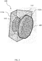
- FIG. 2 is a schematic illustrating an LED traffic signal 100 including an LED signal replaceable light source 110 (e.g., an LED array) that can be implemented within one or more embodiments of the present invention.
- the LED traffic signal 100 includes a housing 112 including a lower closed end 112a and an upper open end 112b connected with and closed by the outer refractive optical element 106.
- the housing 112 is formed of a different material from that of the outer refractive optical element 106.
- the housing can be formed of a plastic or other suitable material.
- the outer refractive optical element 106 is a transparent or clear plastic material.
- the outer refractive optical element 106 can include an inner facetted surface and an outer smooth surface similar to that disclosed within U.S. Patent No. 8,668,351 entitled "LED Traffic Signal and Optical Element therefor" by Eden Dubuc, hereby incorporated herein in its entirety.
- the LED signal replaceable light source 110 includes an electronic driver (e.g., a LED driver) 122, a light source 126 (e.g., an LED array) and other electronic components on a printed circuit board 124.
- the printed circuit board 124 is disposed at the base of the LED signal replaceable light source 110 and the light source 126 is centrally disposed on the printed circuit board 124.
- the LED signal replaceable light source 110 further includes an inner refractive optical element (lens) 128 connected to the printed circuit board 124 and encapsulating the electronic driver 122.
- the inner refractive optical element 128 can include an inner smooth surface and an outer facetted surface similar to that disclosed in U.S. Patent 8,666,351 mentioned above. Light generated by the light source 126 is reflected by the inner refractive optical element 128 and exits through the outer refractive optical element 106.
- the optical axis 102 is an imaginary line between the center region of the LED array 126 to the center region of the outer refractive optical element 106.
- the inner refractive optical element 128 is symmetrical with respect to the optical axis 102. According to alternative embodiments, the inner refractive optical element 114 can be asymmetrical with respect to the optical axis 102.
- the light source 126 is disposed on the printed circuit board 124 and situated between the inner refractive optical element 128 and the lower closed end 112a of the housing 112.
- the LED signal replaceable light source 110 can be suspended within the housing 112 by attaching means or seated in another component situated within housing 112.
- the LED signal replaceable light source 110 can be attached to the lower closed end 112a of the housing such that the printed circuit board 124 is secured to the lower closed end 112a of the housing 112 by connection portions (not shown).
- the electronic driver 122 and other components can be disposed on a side of the printed circuit board 124 opposite that of the light source 126 and connected via wires.
- the components can include a power supply, and other necessary electric components.
- the electronic driver 122 and other components generate heat, therefore it is desirable to dissipate the heat away from the light source 126 to avoid malfunction and unwanted damage to the LED traffic signal 100. Therefore, according to an embodiment of the present invention, electronic driver 122 and other components can be enclosed within a sealant 130 or resin (e.g., silicon) which is capable of dissipating heat.
- the light source 126, printed circuit board 124, the electronic driver 122 enclosed within a sealant 130 are manufactured together as a single unit.
- the LED signal replaceable light source 110 can be removed from the opening at the upper open end 112b of the housing 112 and the outer refractive optical element 106 can be reconnected with the housing 112 after the LED signal replaceable light source is repaired or replaced.
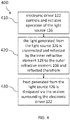
- FIG. 4 is a flow diagram illustrating a method 400 with reference to FIGS. 2 and 3 .
- electronic driver 122 controls and initiates operation of the light source 104.
- the process continues to operation 420 where the light generated from the light source 126 is transmitted and reflected by the inner refractive optical element 128 to the outer refractive optical element 106 and reflected therefrom.
- the process continues to operation 430, where heat generated from the light source 126 is dissipated via a sealant 130 surrounding the electronic driver 122.
- the method 400 further replacing the light source 126 by disconnecting the printed circuit board 124 from the housing 112 via any connecting portions if necessary and replacing the entire unit including the light source 126, the electronic driver 122 and other components, the printed circuit board 124, and the inner refractive optical element 128 (as a single unit).
- Embodiments of the present invention provide a replaceable light source for an LED traffic signal application that can be easily replaced and/or repaired without replace an outer lens of the LED traffic signal.
Landscapes
- Engineering & Computer Science (AREA)
- General Engineering & Computer Science (AREA)
- Physics & Mathematics (AREA)
- General Physics & Mathematics (AREA)
- Microelectronics & Electronic Packaging (AREA)
- Optics & Photonics (AREA)
- Traffic Control Systems (AREA)
- Non-Portable Lighting Devices Or Systems Thereof (AREA)
Abstract
Description
- The present invention relates generally to an LED (light emitting diode) traffic signal application. In particular, the present invention relates to a replaceable LED light source for an LED traffic signal application, having heat dissipation capabilities.
- An LED traffic signal is typically implemented at traffic intersections to control the flow of traffic. The LED traffic signals typically include a light source, a housing and at least one lens to reflect light transmitted from the light source in a direction visible for the drivers.
- As shown in
FIG. 1 , theLED traffic signal 50 is formed of a single unit that includes ahousing 1 having an open-end 2 that is covered by an outer lens or spreadingwindow 3, a plurality ofLEDs 4 located near acenter axis 6 of thehousing 1 and an inner lens 7 (e.g., a Fresnel lens) between the outer lens or spreadingwindow 3 and theLEDs 4. TheLEDs 4 are in a fixed position on the printedcircuit board 5 within thehousing 1. Therefore, when theLEDs 4 malfunction and need to be replaced, the entireLED traffic signal 50 typically needs to be replaced. It is desirable to have a replaceable light source for an LED traffic signal which can be easily replaced or repaired, thereby minimizing maintenance costs and time. - Given the aforementioned deficiencies, a need exists for a replaceable light source without having to replace an outer lens of the LED traffic signal.
- Under certain circumstances, embodiments of the present invention provides a lighting device that includes a housing having an open end and a closed end, a signal replaceable light source that includes a light source connected disposed near the closed end and configured to generate light, an inner refractive optical element encapsulating the light source configured to reflect the light towards the open end, and an electronic component configured to control operation of the light source; and outer refractive optical element disposed at the open end and configured to receive the light from the inner refractive optical element and reflect the light therefrom.
- An embodiment of the present invention includes a lighting device that includes a housing having an open end and a closed end, a lighting component as a single unit, that includes a light source disposed along an optical axis and connected to the closed end and configured to generate light, an electronic component configured to control operation of the light source, and an inner refractive optical element configured to reflect the light, and an outer refractive optical element configured to receive the light from the inner refractive optical element and reflect the light therefrom.
- According to yet another embodiment, a method for operating the lighting device is provided.
- The foregoing has broadly outlined some of the aspects and features of various embodiments, which should be construed to be merely illustrative of various potential applications of the disclosure. Other beneficial results can be obtained by applying the disclosed information in a different manner or by combining various aspects of the disclosed embodiments. Accordingly, other aspects and a more comprehensive understanding may be obtained by referring to the detailed description of the exemplary embodiments taken in conjunction with the accompanying drawings, in addition to the scope defined by the claims.
-
-
FIG. 1 is a schematic illustrating a conventional LED traffic signal. -
FIG. 2 is a schematic illustrating an LED traffic signal including a replaceable light source that can be implemented within one or more embodiments of the present invention. -
FIG. 3 is detailed schematic illustrating the replaceable light source ofFIG. 2 that can be implemented within one or more embodiments of the present invention. -
FIG. 4 is a flow diagram illustrating a method of replacing the replaceable light source that can be implemented within one or more embodiments of the present invention. - The drawings are only for purposes of illustrating preferred embodiments and are not to be construed as limiting the disclosure. Given the following enabling description of the drawings, the novel aspects of the present disclosure should become evident to a person of ordinary skill in the art. This detailed description uses numerical and letter designations to refer to features in the drawings. Like or similar designations in the drawings and description have been used to refer to like or similar parts of embodiments of the invention.
- As required, detailed embodiments are disclosed herein. It must be understood that the disclosed embodiments are merely exemplary of various and alternative forms. As used herein, the word "exemplary" is used expansively to refer to embodiments that serve as illustrations, specimens, models, or patterns. The figures are not necessarily to scale and some features may be exaggerated or minimized to show details of particular components.
- In other instances, well-known components, systems, materials, or methods that are known to those having ordinary skill in the art have not been described in detail in order to avoid obscuring the present disclosure. Therefore, specific structural and functional details disclosed herein are not to be interpreted as limiting, but merely as a basis for the claims and as a representative basis for teaching one skilled in the art.
- As noted above, the embodiments provide a replaceable light source that can be implemented within an LED traffic signal application. The replaceable light source is not limited to being implemented within an LED traffic signal application and can be implemented within any type of suitable lighting application. The replaceable light source can be easily replaced or repaired without having to replace the front or outer lens.
-
FIG. 2 is a schematic illustrating anLED traffic signal 100 including an LED signal replaceable light source 110 (e.g., an LED array) that can be implemented within one or more embodiments of the present invention. As shown inFIG. 2 , theLED traffic signal 100 includes ahousing 112 including a lower closedend 112a and an upperopen end 112b connected with and closed by the outer refractiveoptical element 106. Thehousing 112 is formed of a different material from that of the outer refractiveoptical element 106. The housing can be formed of a plastic or other suitable material. - According to embodiments of the present invention, the outer refractive
optical element 106 is a transparent or clear plastic material. The outer refractiveoptical element 106 can include an inner facetted surface and an outer smooth surface similar to that disclosed withinU.S. Patent No. 8,668,351 entitled "LED Traffic Signal and Optical Element therefor" by Eden Dubuc, hereby incorporated herein in its entirety. - Additional details regarding the LED signal
replaceable light source 110 will be discussed below with reference toFIG. 3 . As shown inFIG. 3 , the LED signalreplaceable light source 110 includes an electronic driver (e.g., a LED driver) 122, a light source 126 (e.g., an LED array) and other electronic components on a printedcircuit board 124. The printedcircuit board 124 is disposed at the base of the LED signalreplaceable light source 110 and thelight source 126 is centrally disposed on the printedcircuit board 124. - The LED signal
replaceable light source 110 further includes an inner refractive optical element (lens) 128 connected to the printedcircuit board 124 and encapsulating theelectronic driver 122. The inner refractiveoptical element 128 can include an inner smooth surface and an outer facetted surface similar to that disclosed inU.S. Patent 8,666,351 mentioned above. Light generated by thelight source 126 is reflected by the inner refractiveoptical element 128 and exits through the outer refractiveoptical element 106. - The
optical axis 102 is an imaginary line between the center region of theLED array 126 to the center region of the outer refractiveoptical element 106. - The inner refractive
optical element 128 is symmetrical with respect to theoptical axis 102. According to alternative embodiments, the inner refractive optical element 114 can be asymmetrical with respect to theoptical axis 102. - Further shown in
FIG. 3 , thelight source 126 is disposed on the printedcircuit board 124 and situated between the inner refractiveoptical element 128 and the lower closedend 112a of thehousing 112. The LED signalreplaceable light source 110 can be suspended within thehousing 112 by attaching means or seated in another component situated withinhousing 112. Alternatively, the LED signalreplaceable light source 110 can be attached to the lower closedend 112a of the housing such that the printedcircuit board 124 is secured to the lower closedend 112a of thehousing 112 by connection portions (not shown). - According to another embodiment, the
electronic driver 122 and other components can be disposed on a side of the printedcircuit board 124 opposite that of thelight source 126 and connected via wires. The components can include a power supply, and other necessary electric components. Theelectronic driver 122 and other components generate heat, therefore it is desirable to dissipate the heat away from thelight source 126 to avoid malfunction and unwanted damage to theLED traffic signal 100. Therefore, according to an embodiment of the present invention,electronic driver 122 and other components can be enclosed within asealant 130 or resin (e.g., silicon) which is capable of dissipating heat. According to an embodiment, thelight source 126, printedcircuit board 124, theelectronic driver 122 enclosed within asealant 130 are manufactured together as a single unit. - Therefore, according to an embodiment, to remove the LED signal replaceable light source is disconnected from the
housing 112 via any connection means, and removed without requiring replacement of the outer refractiveoptical element 106 shown inFIG. 2 . Instead, the LED signalreplaceable light source 110 can be removed from the opening at the upperopen end 112b of thehousing 112 and the outer refractiveoptical element 106 can be reconnected with thehousing 112 after the LED signal replaceable light source is repaired or replaced. -
FIG. 4 is a flow diagram illustrating amethod 400 with reference toFIGS. 2 and3 . As shown inFIG. 4 , atoperation 410,electronic driver 122 controls and initiates operation of the light source 104. Fromoperation 410, the process continues tooperation 420 where the light generated from thelight source 126 is transmitted and reflected by the inner refractiveoptical element 128 to the outer refractiveoptical element 106 and reflected therefrom. Fromoperation 420, the process continues tooperation 430, where heat generated from thelight source 126 is dissipated via asealant 130 surrounding theelectronic driver 122. - According to another embodiment, the
method 400 further replacing thelight source 126 by disconnecting the printedcircuit board 124 from thehousing 112 via any connecting portions if necessary and replacing the entire unit including thelight source 126, theelectronic driver 122 and other components, the printedcircuit board 124, and the inner refractive optical element 128 (as a single unit). - Embodiments of the present invention provide a replaceable light source for an LED traffic signal application that can be easily replaced and/or repaired without replace an outer lens of the LED traffic signal.
- This written description uses examples to disclose the invention including the best mode, and also to enable any person skilled in the art to practice the invention, including making and using any devices or systems and performing any incorporated methods. The patentable scope of the invention is defined by the claims, and may include other examples that occur to those skilled in the art. Such other examples are intended to be within the scope of the claims if they have structural elements that do not differ from the literal language of the claims, or if they include equivalent structural elements with insubstantial differences from the literal languages of the claims.
- Various aspects and embodiments of the present invention are defined by the following clauses:
- 1. A lighting device comprising:
- a housing having an open end and a closed end;
- a signal replaceable light source comprising:
- a light source connected disposed near the closed end and configured to generate light,
- an inner refractive optical element encapsulating the light source configured to reflect the light towards the open end, and
- an electronic component configured to control operation of the light source; and
- outer refractive optical element disposed at the open end and configured to receive the light from the inner refractive optical element and reflect the light therefrom.
- 2. The lighting device of
clause 1, wherein the lighting device is a LED traffic signal. - 3. The lighting device of
clause 2, wherein the outer refractive optical element is connected with and closes the open end of the housing. - 4. The lighting device of
clause 3, wherein the lighting device further comprises a printed circuit board including the light source and the electronic component disposed on a side thereof, and connected via wires. - 5. The lighting device of
clause 4, wherein the inner refractive optical element is connected with the printed circuit board. - 6. The lighting device of
clause 5, wherein the printed circuit board is connected with the closed end of the housing via connecting portions. - 7. The lighting device of
clause 6, wherein the light source, the printed circuit board, and the electronic component form a single unit, to be removable. - 8. The lighting device of
clause 7, wherein the single unit is removable from the lighting device without replacing the outer refractive optical element. - 9. A lighting device comprising:
- a housing having an open end and a closed end;
- a lighting component as a single unit, comprising:
a light source disposed along an optical axis and connected to the closed end and configured to generate light,- an electronic component configured to control operation of the light source, and
- an inner refractive optical element configured to reflect the light; and
- an outer refractive optical element configured to receive the light from the inner refractive optical element and reflect the light therefrom.
- 10. The lighting device of clause 9, wherein the inner refractive optical element is symmetrical with respect to the optical axis.
- 11. The lighting device of clause 10, wherein the lighting component is removable from the housing without replacing the outer refractive optical element.
- 12. The lighting device of clause 9, wherein the lighting device is a LED traffic signal.
- 13. The lighting device of clause 9, wherein the outer refractive optical element is connected with and closes the open end of the housing.
- 14. The lighting device of clause 9, wherein the lighting component further comprises a printed circuit board positioned on a support, and including the light source and the electronic component disposed thereon, and connected via wires.
- 15. The lighting device of clause 14, wherein the inner refractive optical element is connected with the printed circuit board.
- 16. The lighting device of clause 15, wherein the printed circuit board is connected with the closed end of the housing via connecting portions.
- 17. A method for operating a lighting device comprising a lighting component including a light source and an electronic component, the method comprising:
- initiating, via the electronic component, operation of the light source;
- transmitting and reflecting light from the light source, via an inner refractive optical element to an outer refractive optical element and reflecting the light therefrom; and
- dissipating heat generated from the light source and the electronic component, via a sealant encasing the electronic component.
- 18. The method of clause 17, wherein the light source and electronic module are disposed on a printed circuit board and formed of a single unit, wherein the method further comprises:
- replacing the light source by disconnecting the printed circuit board from the housing via connecting portions; and
- replacing the single unit without replacing the outer refractive optical element.
Claims (15)
- A lighting device (100) comprising:a housing (112) having an open end (112b) and a closed end (112a);a signal replaceable light source (110) comprising:a light source (126) connected disposed near the closed end (112a) and configured to generate light,an inner refractive optical element (128) encapsulating the light source (126) configured to reflect the light towards the open end (112b), andan electronic component (122) configured to control operation of the light source (126); andouter refractive optical element (106) disposed at the open end (112b) and configured to receive the light from the inner refractive optical element (128) and reflect the light therefrom.
- The lighting device (100) of claim 1, wherein the lighting device (100) is a LED traffic signal.
- The lighting device (100) of claim 1 or claim 2, wherein the outer refractive optical element (106) is connected with and closes the open end (112b) of the housing (112).
- The lighting device (100) of any preceding claims, wherein the lighting device (100) further comprises a printed circuit board (124) including the light source (126) and the electronic component (122) disposed on a side thereof, and connected via wires.
- The lighting device (100) of claim 4, wherein the inner refractive optical element (128) is connected with the printed circuit board (124).
- The lighting device (100) of claim 5, wherein the printed circuit board (124) is connected with the closed end (112a) of the housing (112) via connecting portions.
- The lighting device (100) of claim 6, wherein the light source (126), the printed circuit board (124), and the electronic component (122) form a single unit, to be removable.
- The lighting device (100) of claim 7, wherein the single unit is removable from the lighting device (100) without replacing the outer refractive optical element (106).
- A lighting device (100) comprising:a housing (112) having an open end (112b) and a closed end (112a);a lighting component as a single unit (110), comprising:a light source (126) disposed along an optical axis and connected to the closed end (112a) and configured to generate light,an electronic component (122) configured to control operation of the light source (126), andan inner refractive optical element (128) configured to reflect the light;an outer refractive optical element (106) configured to receive the light from the inner refractive optical element (128) and reflect the light therefrom.
- The lighting device (100) of claim 9, wherein the inner refractive optical element (128) is symmetrical with respect to the optical axis.
- The lighting device (100) of claim 9 or claim 10, wherein the lighting device (100) is a LED traffic signal.
- The lighting device (100) of any of claims 9 to 11, wherein the outer refractive optical element (106) is connected with and closes the open end (112b) of the housing (112).
- The lighting device (100) of any of claims 9 to 12, wherein the lighting component further comprises a printed circuit board (124) positioned on a support, and including the light source (126) and the electronic component (122) disposed thereon, and connected via wires.
- A method for operating a lighting device (100) comprising a lighting component including a light source (126) and an electronic component (122), the method comprising:initiating, via the electronic component (122), operation of the light source (126);transmitting and reflecting light from the light source (126), via an inner refractive optical element (128) to an outer refractive optical element (106) and reflecting the light therefrom; anddissipating heat generated from the light source (126) and the electronic component (122), via a sealant encasing the electronic component (122).
- The method of claim 14, wherein the light source (126) and electronic module are disposed on a printed circuit board (124) and formed of a single unit, wherein the method further comprises:replacing the light source (126) by disconnecting the printed circuit board (124) from the housing (112) via connecting portions; andreplacing the single unit without replacing the outer refractive optical element (106).
Applications Claiming Priority (1)
| Application Number | Priority Date | Filing Date | Title |
|---|---|---|---|
| US15/644,887 US10619829B2 (en) | 2017-07-10 | 2017-07-10 | Replaceable LED light source for an LED traffic signal application |
Publications (2)
| Publication Number | Publication Date |
|---|---|
| EP3428516A2 true EP3428516A2 (en) | 2019-01-16 |
| EP3428516A3 EP3428516A3 (en) | 2019-03-06 |
Family
ID=62909385
Family Applications (1)
| Application Number | Title | Priority Date | Filing Date |
|---|---|---|---|
| EP18182403.8A Withdrawn EP3428516A3 (en) | 2017-07-10 | 2018-07-09 | Replaceable led light source for an led traffic signal application |
Country Status (2)
| Country | Link |
|---|---|
| US (1) | US10619829B2 (en) |
| EP (1) | EP3428516A3 (en) |
Families Citing this family (1)
| Publication number | Priority date | Publication date | Assignee | Title |
|---|---|---|---|---|
| CZ309937B6 (en) | 2023-02-17 | 2024-02-14 | AŽD Praha s.r.o. | A flashlight, especially for light signaling intended for traffic control on roads |
Citations (2)
| Publication number | Priority date | Publication date | Assignee | Title |
|---|---|---|---|---|
| US8666351B2 (en) | 2010-06-03 | 2014-03-04 | Broadcom Corporation | Multiple band saw-less receiver including a frequency translated BPF |
| US8668351B2 (en) | 2008-09-04 | 2014-03-11 | GE Lighting Solutions, LLC | LED traffic signal and optical element therefor |
Family Cites Families (17)
| Publication number | Priority date | Publication date | Assignee | Title |
|---|---|---|---|---|
| US6796698B2 (en) * | 2002-04-01 | 2004-09-28 | Gelcore, Llc | Light emitting diode-based signal light |
| US6981784B2 (en) | 2002-05-30 | 2006-01-03 | Gelcore, Llc | Side projecting LED signal |
| US6911915B2 (en) | 2002-09-04 | 2005-06-28 | Leotek Electronics Corporation | Compact light emitting diode retrofit lamp and method for traffic signal lights |
| US6905227B2 (en) * | 2002-09-04 | 2005-06-14 | Leotek Electronics Corporation | Light emitting diode retrofit module for traffic signal lights |
| US7237924B2 (en) * | 2003-06-13 | 2007-07-03 | Lumination Llc | LED signal lamp |
| US7868903B2 (en) | 2004-10-14 | 2011-01-11 | Daktronics, Inc. | Flexible pixel element fabrication and sealing method |
| US7465075B2 (en) * | 2005-03-21 | 2008-12-16 | Visteon Global Technologies, Inc. | Lens assembly for an automobile light assembly having LED light source |
| US7434968B2 (en) | 2005-12-21 | 2008-10-14 | Leotek Electronics Corporation | Traffic signal lamp assembly and method of replacing same |
| WO2007106411A2 (en) * | 2006-03-10 | 2007-09-20 | Dialight Corporation | Light emitting diode module with improved light distribution uniformity |
| US7883226B2 (en) | 2007-03-05 | 2011-02-08 | Intematix Corporation | LED signal lamp |
| US8152334B2 (en) * | 2008-09-08 | 2012-04-10 | Lsi Industries, Inc. | LED lighting assembly with adjustment means |
| AU2009222549A1 (en) | 2009-10-02 | 2011-04-21 | Lumn Pty Ltd | Traffic Signal |
| GB2486236A (en) | 2010-12-08 | 2012-06-13 | Global Design Solutions Ltd | A Light Fitting |
| US8833978B2 (en) * | 2011-10-25 | 2014-09-16 | Leotek Electronics Corporation | Traffic signal light device |
| US8888316B2 (en) | 2011-12-20 | 2014-11-18 | Innovative Lighting, Inc. | Lenticular LED light source replacement for fluorescent in troffer |
| DE102012202353A1 (en) | 2012-02-16 | 2013-08-22 | Osram Gmbh | Light module circuit board |
| US10100984B2 (en) * | 2015-10-15 | 2018-10-16 | GE Lighting Solutions, LLC | Indirect light mixing LED module for point-source applications |
-
2017
- 2017-07-10 US US15/644,887 patent/US10619829B2/en active Active
-
2018
- 2018-07-09 EP EP18182403.8A patent/EP3428516A3/en not_active Withdrawn
Patent Citations (2)
| Publication number | Priority date | Publication date | Assignee | Title |
|---|---|---|---|---|
| US8668351B2 (en) | 2008-09-04 | 2014-03-11 | GE Lighting Solutions, LLC | LED traffic signal and optical element therefor |
| US8666351B2 (en) | 2010-06-03 | 2014-03-04 | Broadcom Corporation | Multiple band saw-less receiver including a frequency translated BPF |
Also Published As
| Publication number | Publication date |
|---|---|
| US10619829B2 (en) | 2020-04-14 |
| US20190011114A1 (en) | 2019-01-10 |
| EP3428516A3 (en) | 2019-03-06 |
Similar Documents
| Publication | Publication Date | Title |
|---|---|---|
| EP3199861B1 (en) | Led lamp and led light source module thereof | |
| US10401002B2 (en) | LED lamp and LED light source module thereof | |
| US20110122598A1 (en) | Led illuminator with improved beam quality | |
| JP6404363B2 (en) | Lighting device and display device | |
| EP3830479A1 (en) | Lighting device with adjustable light distribution | |
| CA2559514A1 (en) | Traffic signal lamp assembly and method of replacing same | |
| CN107023793A (en) | Automobile greeting lamp and the automobile with this greeting lamp | |
| CN102658790A (en) | Automobile vehicle lighting and/or signaling device | |
| EP3462083A1 (en) | A zoom led lamp | |
| KR101446063B1 (en) | Variable information Sign | |
| EP3179469B1 (en) | Mark and sign illuminating device | |
| US10619829B2 (en) | Replaceable LED light source for an LED traffic signal application | |
| KR101100328B1 (en) | LED signs using LED | |
| CN201259565Y (en) | Integrated type laser scanning head | |
| KR20100004149U (en) | Optical fiber condensing polygonal lens structure | |
| EP1507926A1 (en) | Device and method for sign illumination | |
| KR200400072Y1 (en) | Channel sign using plane lighting | |
| CN209418069U (en) | A kind of anti-LED display module smashed | |
| CN105334663A (en) | Side-entry backlight module with protection covers | |
| CN207250056U (en) | A kind of backlight type matrix group | |
| KR20220141424A (en) | High-brightness double-sided signage display device with improved cooling efficiency | |
| KR20190001478A (en) | Double surfaces emitting type advertisement apparatus and manufacturing method thereof | |
| EP2942258A1 (en) | Led traffic signal light module | |
| KR101208702B1 (en) | Back light unit for road information-image display system and road information-image display system including the same | |
| KR101656501B1 (en) | back plate for daytime running light module |
Legal Events
| Date | Code | Title | Description |
|---|---|---|---|
| PUAI | Public reference made under article 153(3) epc to a published international application that has entered the european phase |
Free format text: ORIGINAL CODE: 0009012 |
|
| STAA | Information on the status of an ep patent application or granted ep patent |
Free format text: STATUS: THE APPLICATION HAS BEEN PUBLISHED |
|
| AK | Designated contracting states |
Kind code of ref document: A2 Designated state(s): AL AT BE BG CH CY CZ DE DK EE ES FI FR GB GR HR HU IE IS IT LI LT LU LV MC MK MT NL NO PL PT RO RS SE SI SK SM TR |
|
| AX | Request for extension of the european patent |
Extension state: BA ME |
|
| PUAL | Search report despatched |
Free format text: ORIGINAL CODE: 0009013 |
|
| AK | Designated contracting states |
Kind code of ref document: A3 Designated state(s): AL AT BE BG CH CY CZ DE DK EE ES FI FR GB GR HR HU IE IS IT LI LT LU LV MC MK MT NL NO PL PT RO RS SE SI SK SM TR |
|
| AX | Request for extension of the european patent |
Extension state: BA ME |
|
| RIC1 | Information provided on ipc code assigned before grant |
Ipc: F21V 5/00 20180101AFI20190130BHEP Ipc: G08G 1/095 20060101ALN20190130BHEP Ipc: F21V 7/00 20060101ALI20190130BHEP Ipc: F21Y 115/10 20160101ALN20190130BHEP Ipc: F21K 9/00 20160101ALI20190130BHEP Ipc: F21V 19/04 20060101ALI20190130BHEP Ipc: F21V 29/503 20150101ALN20190130BHEP Ipc: F21V 17/00 20060101ALN20190130BHEP |
|
| STAA | Information on the status of an ep patent application or granted ep patent |
Free format text: STATUS: THE APPLICATION IS DEEMED TO BE WITHDRAWN |
|
| 18D | Application deemed to be withdrawn |
Effective date: 20190907 |