EP3428484A1 - Control device for continuously variable transmission and control method for continuously variable transmission - Google Patents
Control device for continuously variable transmission and control method for continuously variable transmission Download PDFInfo
- Publication number
- EP3428484A1 EP3428484A1 EP17762972.2A EP17762972A EP3428484A1 EP 3428484 A1 EP3428484 A1 EP 3428484A1 EP 17762972 A EP17762972 A EP 17762972A EP 3428484 A1 EP3428484 A1 EP 3428484A1
- Authority
- EP
- European Patent Office
- Prior art keywords
- continuously variable
- variable transmission
- shift control
- control value
- speed ratio
- Prior art date
- Legal status (The legal status is an assumption and is not a legal conclusion. Google has not performed a legal analysis and makes no representation as to the accuracy of the status listed.)
- Withdrawn
Links
- 230000005540 biological transmission Effects 0.000 title claims abstract description 93
- 238000000034 method Methods 0.000 title claims description 11
- 238000012545 processing Methods 0.000 claims description 14
- 101000655384 Mus musculus Testis-expressed protein 9 Proteins 0.000 description 6
- 238000010586 diagram Methods 0.000 description 6
- 239000003112 inhibitor Substances 0.000 description 2
- 230000000994 depressogenic effect Effects 0.000 description 1
- 230000000694 effects Effects 0.000 description 1
- 230000004043 responsiveness Effects 0.000 description 1
- 230000001052 transient effect Effects 0.000 description 1
Images


Classifications
-
- F—MECHANICAL ENGINEERING; LIGHTING; HEATING; WEAPONS; BLASTING
- F16—ENGINEERING ELEMENTS AND UNITS; GENERAL MEASURES FOR PRODUCING AND MAINTAINING EFFECTIVE FUNCTIONING OF MACHINES OR INSTALLATIONS; THERMAL INSULATION IN GENERAL
- F16H—GEARING
- F16H59/00—Control inputs to control units of change-speed- or reversing-gearings for conveying rotary motion
- F16H59/36—Inputs being a function of speed
- F16H59/38—Inputs being a function of speed of gearing elements
-
- F—MECHANICAL ENGINEERING; LIGHTING; HEATING; WEAPONS; BLASTING
- F16—ENGINEERING ELEMENTS AND UNITS; GENERAL MEASURES FOR PRODUCING AND MAINTAINING EFFECTIVE FUNCTIONING OF MACHINES OR INSTALLATIONS; THERMAL INSULATION IN GENERAL
- F16H—GEARING
- F16H61/00—Control functions within control units of change-speed- or reversing-gearings for conveying rotary motion ; Control of exclusively fluid gearing, friction gearing, gearings with endless flexible members or other particular types of gearing
- F16H61/66—Control functions within control units of change-speed- or reversing-gearings for conveying rotary motion ; Control of exclusively fluid gearing, friction gearing, gearings with endless flexible members or other particular types of gearing specially adapted for continuously variable gearings
- F16H61/662—Control functions within control units of change-speed- or reversing-gearings for conveying rotary motion ; Control of exclusively fluid gearing, friction gearing, gearings with endless flexible members or other particular types of gearing specially adapted for continuously variable gearings with endless flexible members
- F16H61/66254—Control functions within control units of change-speed- or reversing-gearings for conveying rotary motion ; Control of exclusively fluid gearing, friction gearing, gearings with endless flexible members or other particular types of gearing specially adapted for continuously variable gearings with endless flexible members controlling of shifting being influenced by a signal derived from the engine and the main coupling
- F16H61/66259—Control functions within control units of change-speed- or reversing-gearings for conveying rotary motion ; Control of exclusively fluid gearing, friction gearing, gearings with endless flexible members or other particular types of gearing specially adapted for continuously variable gearings with endless flexible members controlling of shifting being influenced by a signal derived from the engine and the main coupling using electrical or electronical sensing or control means
-
- B—PERFORMING OPERATIONS; TRANSPORTING
- B60—VEHICLES IN GENERAL
- B60W—CONJOINT CONTROL OF VEHICLE SUB-UNITS OF DIFFERENT TYPE OR DIFFERENT FUNCTION; CONTROL SYSTEMS SPECIALLY ADAPTED FOR HYBRID VEHICLES; ROAD VEHICLE DRIVE CONTROL SYSTEMS FOR PURPOSES NOT RELATED TO THE CONTROL OF A PARTICULAR SUB-UNIT
- B60W10/00—Conjoint control of vehicle sub-units of different type or different function
- B60W10/10—Conjoint control of vehicle sub-units of different type or different function including control of change-speed gearings
- B60W10/101—Infinitely variable gearings
- B60W10/107—Infinitely variable gearings with endless flexible members
-
- F—MECHANICAL ENGINEERING; LIGHTING; HEATING; WEAPONS; BLASTING
- F16—ENGINEERING ELEMENTS AND UNITS; GENERAL MEASURES FOR PRODUCING AND MAINTAINING EFFECTIVE FUNCTIONING OF MACHINES OR INSTALLATIONS; THERMAL INSULATION IN GENERAL
- F16H—GEARING
- F16H59/00—Control inputs to control units of change-speed- or reversing-gearings for conveying rotary motion
- F16H59/14—Inputs being a function of torque or torque demand
-
- F—MECHANICAL ENGINEERING; LIGHTING; HEATING; WEAPONS; BLASTING
- F16—ENGINEERING ELEMENTS AND UNITS; GENERAL MEASURES FOR PRODUCING AND MAINTAINING EFFECTIVE FUNCTIONING OF MACHINES OR INSTALLATIONS; THERMAL INSULATION IN GENERAL
- F16H—GEARING
- F16H59/00—Control inputs to control units of change-speed- or reversing-gearings for conveying rotary motion
- F16H59/36—Inputs being a function of speed
- F16H59/38—Inputs being a function of speed of gearing elements
- F16H59/40—Output shaft speed
-
- F—MECHANICAL ENGINEERING; LIGHTING; HEATING; WEAPONS; BLASTING
- F16—ENGINEERING ELEMENTS AND UNITS; GENERAL MEASURES FOR PRODUCING AND MAINTAINING EFFECTIVE FUNCTIONING OF MACHINES OR INSTALLATIONS; THERMAL INSULATION IN GENERAL
- F16H—GEARING
- F16H61/00—Control functions within control units of change-speed- or reversing-gearings for conveying rotary motion ; Control of exclusively fluid gearing, friction gearing, gearings with endless flexible members or other particular types of gearing
- F16H61/02—Control functions within control units of change-speed- or reversing-gearings for conveying rotary motion ; Control of exclusively fluid gearing, friction gearing, gearings with endless flexible members or other particular types of gearing characterised by the signals used
-
- F—MECHANICAL ENGINEERING; LIGHTING; HEATING; WEAPONS; BLASTING
- F16—ENGINEERING ELEMENTS AND UNITS; GENERAL MEASURES FOR PRODUCING AND MAINTAINING EFFECTIVE FUNCTIONING OF MACHINES OR INSTALLATIONS; THERMAL INSULATION IN GENERAL
- F16H—GEARING
- F16H61/00—Control functions within control units of change-speed- or reversing-gearings for conveying rotary motion ; Control of exclusively fluid gearing, friction gearing, gearings with endless flexible members or other particular types of gearing
- F16H61/66—Control functions within control units of change-speed- or reversing-gearings for conveying rotary motion ; Control of exclusively fluid gearing, friction gearing, gearings with endless flexible members or other particular types of gearing specially adapted for continuously variable gearings
-
- F—MECHANICAL ENGINEERING; LIGHTING; HEATING; WEAPONS; BLASTING
- F16—ENGINEERING ELEMENTS AND UNITS; GENERAL MEASURES FOR PRODUCING AND MAINTAINING EFFECTIVE FUNCTIONING OF MACHINES OR INSTALLATIONS; THERMAL INSULATION IN GENERAL
- F16H—GEARING
- F16H61/00—Control functions within control units of change-speed- or reversing-gearings for conveying rotary motion ; Control of exclusively fluid gearing, friction gearing, gearings with endless flexible members or other particular types of gearing
- F16H61/66—Control functions within control units of change-speed- or reversing-gearings for conveying rotary motion ; Control of exclusively fluid gearing, friction gearing, gearings with endless flexible members or other particular types of gearing specially adapted for continuously variable gearings
- F16H61/662—Control functions within control units of change-speed- or reversing-gearings for conveying rotary motion ; Control of exclusively fluid gearing, friction gearing, gearings with endless flexible members or other particular types of gearing specially adapted for continuously variable gearings with endless flexible members
- F16H61/66227—Control functions within control units of change-speed- or reversing-gearings for conveying rotary motion ; Control of exclusively fluid gearing, friction gearing, gearings with endless flexible members or other particular types of gearing specially adapted for continuously variable gearings with endless flexible members controlling shifting exclusively as a function of speed and torque
-
- F—MECHANICAL ENGINEERING; LIGHTING; HEATING; WEAPONS; BLASTING
- F16—ENGINEERING ELEMENTS AND UNITS; GENERAL MEASURES FOR PRODUCING AND MAINTAINING EFFECTIVE FUNCTIONING OF MACHINES OR INSTALLATIONS; THERMAL INSULATION IN GENERAL
- F16H—GEARING
- F16H61/00—Control functions within control units of change-speed- or reversing-gearings for conveying rotary motion ; Control of exclusively fluid gearing, friction gearing, gearings with endless flexible members or other particular types of gearing
- F16H61/70—Control functions within control units of change-speed- or reversing-gearings for conveying rotary motion ; Control of exclusively fluid gearing, friction gearing, gearings with endless flexible members or other particular types of gearing specially adapted for change-speed gearing in group arrangement, i.e. with separate change-speed gear trains arranged in series, e.g. range or overdrive-type gearing arrangements
- F16H61/702—Control functions within control units of change-speed- or reversing-gearings for conveying rotary motion ; Control of exclusively fluid gearing, friction gearing, gearings with endless flexible members or other particular types of gearing specially adapted for change-speed gearing in group arrangement, i.e. with separate change-speed gear trains arranged in series, e.g. range or overdrive-type gearing arrangements using electric or electrohydraulic control means
-
- F—MECHANICAL ENGINEERING; LIGHTING; HEATING; WEAPONS; BLASTING
- F16—ENGINEERING ELEMENTS AND UNITS; GENERAL MEASURES FOR PRODUCING AND MAINTAINING EFFECTIVE FUNCTIONING OF MACHINES OR INSTALLATIONS; THERMAL INSULATION IN GENERAL
- F16H—GEARING
- F16H59/00—Control inputs to control units of change-speed- or reversing-gearings for conveying rotary motion
- F16H59/14—Inputs being a function of torque or torque demand
- F16H2059/148—Transmission output torque, e.g. measured or estimated torque at output drive shaft
-
- F—MECHANICAL ENGINEERING; LIGHTING; HEATING; WEAPONS; BLASTING
- F16—ENGINEERING ELEMENTS AND UNITS; GENERAL MEASURES FOR PRODUCING AND MAINTAINING EFFECTIVE FUNCTIONING OF MACHINES OR INSTALLATIONS; THERMAL INSULATION IN GENERAL
- F16H—GEARING
- F16H59/00—Control inputs to control units of change-speed- or reversing-gearings for conveying rotary motion
- F16H59/36—Inputs being a function of speed
- F16H59/38—Inputs being a function of speed of gearing elements
- F16H59/42—Input shaft speed
Definitions
- JP11-194801A discloses a following technique. That is, as a technique of controlling a sliding mode of a continuously variable transmission, a technique which sets a switching surface on a phase space of the sliding mode control so as to have a phase advance/delay characteristic corresponding to an actual value of a hunting frequency is disclosed (see paragraph [0120]).
- Each of the pulleys 21 and 22 includes a fixed conical plate, a movable conical plate which is disposed in a state in which a sheave surface is opposite to the fixed conical plate and has a V-shaped groove between the fixed conical plate and the movable conical plate, and a hydraulic cylinder which is disposed on a rear surface of the movable conical plate to axially displace the movable conical plate.
- the pulley 21 includes a hydraulic cylinder 23a as a hydraulic cylinder and the pulley 22 includes a hydraulic cylinder 23b as a hydraulic cylinder.
- the sub-transmission mechanism 30 may be directly connected to an output shaft of the variator 20 as in the example or may be connected to the output shaft via a power transmission mechanism such as a shift or gear train. Alternately, the sub-transmission mechanism 30 may be connected to the input shaft of the variator 20.
- the hydraulic pressure control circuit 11 is configured by a plurality of flow passages and a plurality of hydraulic pressure control valves.
- the hydraulic pressure control circuit 11 controls the plurality of hydraulic pressure control valves based on a shift control signal from the transmission controller 12 to switch a hydraulic pressure supply passage. Further, the hydraulic pressure control circuit 11 adjusts a necessary hydraulic pressure from a hydraulic pressure generated by the oil supplied from the oil pump 10 and supplies the adjusted hydraulic pressure to individual parts of the transmission 4. By doing this, shift of the variator 20, change of a gear position of the sub-transmission mechanism 30, and engagement/disengagement of the LU clutch 2a are performed.
- a shift control program of the transmission 4 and various maps used for the shift control program are stored in the memory device 122.
- the CPU 121 reads and executes the shift control program stored in the memory device 122 and generates a shift control signal based on various signals input via the input interface 123.
- the CPU 121 outputs the generated shift control signal to the hydraulic pressure control circuit 11 via the output interface 124.
- Various values which are used for arithmetic processings of the CPU 121 and arithmetic results of the CPU 121 are appropriately stored in the memory device.
- a longitudinal vibration may be generated at a PT resonance frequency Fpt which is a resonance frequency of the power train PT.
- Fpt a resonance frequency of the power train PT.
- FIG. 3 is a functional block diagram of a controller 12 illustrating a main component of shift control.
- the controller 12 has a hydraulic pressure control FF control unit 131, a shift control FB control unit 132, a phase advance compensator 133, an operating region determining unit 134, a switch unit 135, and a filter unit 136.
- FF is an abbreviation of feedforward
- FB is an abbreviation of feedback.
- the target speed ratio Ratio_T of the variator 20 is input to the hydraulic pressure control FF control unit 131 and the shift control FB control unit 132.
- the target speed ratio Ratio_T is a final desired shift control value having the speed ratio Ratio as a shift control value and is set in advance in accordance with a driving condition of the vehicle in a shift map.
- the driving condition of the vehicle is a vehicle speed VSP and an accelerator pedal opening APO.
- the hydraulic pressure FF control unit 131 calculates an indicating pressure Psec_D for performing FF control on the secondary pressure Psec, based on the target speed ratio Ratio_T.
- the indicating pressure Psec_D is set to secure a fastening force of the belt 23.
- the hydraulic pressure control FF control unit 131 outputs the calculated indicating pressure Psec_D to the shift control FB control unit 132.
- the shift control FB control unit 132 calculates an indicating pressure Ppri_D for performing FB control on the primary pressure Ppri, based on the actual speed ratio Ratio_A and the target speed ratio Ratio_T of the variator 20, and the indicating pressure Psec_D.
- the indicating pressure Ppri_D is set as a transient desired primary pressure until the actual pressure Ppri_A of the primary pressure Ppri reaches a target primary pressure Ppri_T.
- the target primary pressure Ppri_T is a primary pressure Ppri corresponding to the target speed ratio Ratio_T.
- the shift control FB control unit 132 outputs the calculated indicating pressure Ppri_D to the phase advance compensator 133 and the switch unit 135.
- the phase advance compensator 133 performs phase advance compensation of the indicating pressure Ppri_D.
- the phase advance compensator 133 may be, for example, configured by a filter having a time constant C (s).
- the phase advance compensator 133 corresponds to a compensating unit.
- FIG. 4 is a view for explaining an advance compensation region R.
- the advance compensating region R is set in accordance with the rotation speed Npri and an input torque Tsec to the pulley 22.
- the input torque Tsec may be calculated, for example, as a value obtained by multiplying the engine torque Te by the speed ratio set between the engine 1 and the pulley 22, that is, a gear ratio of the first gear train 3 and the speed ratio Ratio of the variator 20 in this embodiment.
- the advance compensating region R includes a region R1 where the input torque Tsec is smaller than a predetermined torque Tsec1.
- the advance compensating region R further includes a region R2 where the input torque Tsec is equal to or larger than a predetermined torque Tsec1 and the rotation speed Npri is equal to or higher than a predetermined rotation speed Npri1.
- the predetermined rotation speed Npri1 is set to define a boundary B.
- the boundary B is a straight line in which the rotation speed Npri increases in proportion to the input torque Tsec.
- the region partitioned from the advance compensating region R at the boundary B is a rebound region RX.
- the rebound region RX will be described below.
- the advance compensating region R is further set in accordance with the speed ratio Ratio, the changing rate ⁇ , and the engagement state of the LU clutch 2a so that the advance compensating region R is further set in accordance therewith.
- the operating points M is the same as the above.
- the switch unit 135 selects the indicating pressure Ppri_D1 as the indicating pressure Ppri_D.
- the switch unit 135 configures a setting unit 139 which sets the indicating pressure Ppri_D2 as an indicating pressure Ppri_D, in accordance with the rotation speed Npri, the input torque Tsec, the speed ratio Ratio, and the changing rate ⁇ , together with the operation region determining unit 134.
- An actuator 111 controls the primary pressure Ppri and an actuator 112 controls the secondary pressure Psec.
- the actuator 111 and the actuator 112 are specifically hydraulic pressure control valves and provided in the hydraulic pressure control circuit 111.
- the indicating pressure Ppri_D which is selected from the switch unit 135 is input to the actuator 111 and the indicating pressure Psec_D from the hydraulic pressure control FF control unit 131 is input to the actuator 112.
- the actuator 111 controls the primary pressure Ppri such that an actual pressure Ppri_A of the primary pressure Ppri becomes the indicating pressure Ppri_D and the actuator 112 controls the secondary pressure Ppri such that an actual pressure Psec_A of the secondary pressure Psec becomes the indicating pressure Psec_D.
- the actual pressure Ppri_A configures an actual shift control value and the indicating pressure Ppri_D configures a desired shift control value.
- the speed ratio Ratio is controlled such that the actual speed ratio Ratio_A becomes a desired speed ratio Ratio_D.
- the actual shift control value and the desired shift control value may be configured by an actual speed ratio Ratio_A and a desired speed ratio Ratio_D which have the speed ratio Ratio as a shift control value.
- the fastening force of the belt 23 is secured by the actual pressure Psec_A. Therefore, even though the input torque Tpri to the pulley 21 corresponding to the engine torque Te is input to the variator 20, the slippage of the belt 23 is not caused.
- the actual speed ratio Ratio_A is input to the engine 1. Further, the actual speed ratio Ratio_A is input to the shift control FB control unit 132 via the filter unit 136. A value calculated by the controller 12 may be applied as the actual speed ratio Ratio_A, based on the outputs of the rotation speed sensor 4 and the rotation speed sensor 43.
- the filter unit 136 performs the filter processing of the actual speed ratio Ratio_A.
- the filter unit 136 configures a high-order low pass filter.
- the filter unit 136 for example, has a plurality of first-order low pass filters.
- step S1 the controller 12 determines whether the input torque Tsec is smaller than a predetermined torque Tsec1. When it is determined to be negative in step S1, the processing proceeds to step S2.
- step S3 the controller 12 determines whether the speed ratio Ratio is higher than a predetermined speed ratio Ratio 1.
- the operating region determining unit 134 specifically, determines whether the actual speed ratio Ratio_A or the desired speed ratio Ratio_D is higher than a predetermined speed ratio Ratio 1.
- Whether the speed ratio Ratio is higher than the predetermined speed ratio Ratio may be determined by determining whether OD switch 49 is off.
- the actual speed ratio Ratio_A and the desired speed ratio Ratio_D may be arithmetic values. When it is determined to be positive in step S3, the processing proceeds to step S4.
- step S4 the controller 12 determines whether the changing rate ⁇ is higher than a predetermined value ⁇ 1. It may be determined whether the changing rate ⁇ is higher than a predetermined value ⁇ 1 by determining whether the speed ratio Ratio is fixed by the driver's manipulation, for example, whether a manual range is selected by a select lever, based on the output of the inhibitor switch 47. When it is determined to be positive in step S4, the processing proceeds to step S5.
- step S5 the controller 12 determines whether the LU clutch 2a is engaged. It may be determined whether the LU clutch 12 is engaged, based on the output of the hydraulic pressure sensor 50.
- step S5 When it is determined to be positive in step S5, the processing proceeds to step S5 and the controller 12 determines that the operating point M is in the advance compensating region R.
- step S5 When it is determined to be negative in step S5, the processing proceeds to step S7 and the controller 12 determines that the operating point M is not in an advance compensating region R. When it is determined to be negative in steps S2 to S4, the same is applied.
- the controller 12 configures a control device of a continuously variable transmission which performs shift control of the transmission 4 such that the actual pressure Ppri_A becomes an indicating pressure Ppri_D.
- the controller 12 has a phase advance compensator 133 which performs advance compensation of the indicating pressure Ppri_D and a setting unit 139 which sets an indicating pressure Ppri_D2 at which the advance compensation is performed by the phase advance compensator 133 as an indicting pressure Ppri_D in accordance with the rotation speed Npri, the input torque Tsec, the speed ratio Ratio, and the changing rate ⁇ .
- the controller 12 With the above-described configuration, it is possible to set the indicating pressure Ppri_D2 in the region where the longitudinal vibration is generated, as the indicating pressure Ppri_D. Therefore, it is possible to improve the stability of the speed ratio Ratio by the phase advance compensation of the indicating pressure Ppri_D as necessary and thus it is possible to appropriately improve the longitudinal vibration of the transmission 4 by converging the longitudinal vibration.
- the stability of the speed ratio Ratio is increased by the phase advance compensation so that the control responsiveness of the speed ratio Ratio is also improved. Further, by the controller 12 with the above-described configuration, the stability of the speed ratio Ratio is increased as necessary so that when it is not necessary to increase the stability of the speed ratio Ratio, the vibration of the actual pressure Ppri_A may be suppressed.
- the controller 12 further includes a filter unit 136 which performs the filter processing of the actual speed ratio Ratio_A and configures a higher-order low pass filter.
- the controller 12 With the above-described configuration, as compared with a case when a slight delay occurs in a region below a frequency to be eliminated using the first-order low pass filter, the delay is improved and thus, the phase of the indicating pressure Ppri_D may be further advanced.
- the setting unit 139 in the controller 12 sets the indicating pressure Ppri_D2 as the indicating pressure Ppri_D.
- a region where the longitudinal vibration is generated is considered as an advance compensating region R and the stability of the speed ratio Ratio is increased so that the longitudinal vibration may be appropriately improved.
- the advance compensating region R includes a region R1 where the input torque Tsec is smaller than a predetermined torque Tsec1.
- the setting unit 139 sets the indicating pressure Ppri_D2 as the indicating pressure Ppri_D.
- the setting unit 139 sets the indicating pressure Ppri_D2 as the indicating pressure Ppri_D according to all of four parameters of the rotation speed Npri, the input torque Tsec, the speed ratio Ratio, and the change rate ⁇ .
- the setting unit 139 may be configured to set the indicating pressure Ppri_D2 as the indicating pressure Ppri_D in accordance with at least one parameter of the input torque Tsec, the speed ratio Ratio, or the change rate ⁇ . Also in this case, the longitudinal vibration may be appropriately improved by appropriately increasing the stability of the speed ratio Ratio in relation to the parameter.
- the controller 12 does not determine the speed ratio Ratio, the changing rate ⁇ , and the engagement state of the LU clutch 2a when it is determined whether the operating point M is in the advance compensating region, but may be separately determine the speed ratio Ratio, the changing rate ⁇ , and the engagement state of the LU clutch 2a.
- the operating region determining unit 134 and the switch unit 135 configure the setting unit 139.
- the setting unit 139 is configured by the switch unit 135 which selects the indicating pressure Ppri_D according to the determining result of the operating region determining unit 134.
- the controller 12 is configured as a control device of the continuously variable transmission.
- the control device of the continuously variable transmission may be implemented by a plurality of controllers.
Landscapes
- Engineering & Computer Science (AREA)
- General Engineering & Computer Science (AREA)
- Mechanical Engineering (AREA)
- Chemical & Material Sciences (AREA)
- Combustion & Propulsion (AREA)
- Transportation (AREA)
- Control Of Transmission Device (AREA)
Abstract
Description
- The present invention relates to a control device of a continuously variable transmission and a control method of a continuously variable transmission.
- Regarding shift control of a continuously variable transmission,
JP11-194801A - In the continuously variable transmission, longitudinal vibration which causes longitudinal rocking at a resonance frequency of a power train is generated. When a stability of a speed ratio of the continuously variable transmission with respect to a torque fluctuation of the power train is insufficient, it is considered that the torque fluctuation is coupled to the shift of the continuously variable transmission to generate the longitudinal vibration. When the longitudinal vibration is generated, there is a fear that a drivability of a vehicle mounted with a continuously variable transmission is deteriorated. Therefore, a technique for appropriately improving the longitudinal vibration of the continuously variable transmission is desired.
- The present invention has been made in an effort to provide a control device of a continuously variable transmission and a control method of a continuously variable transmission which are capable of appropriately improving a longitudinal vibration of the continuously variable transmission.
- In one aspect of the present invention, a control device of a continuously variable transmission which performs shift control of the continuously variable transmission such that an actual shift control value becomes a desired shift control value is provided. The control device in this aspect includes an advance compensating unit configured to perform advance compensation of the desired shift control value, and a setting unit configured to set a compensated desired shift control value on which the advance compensation is performed by the advance compensating unit as the desired shift control value, in accordance with at least one of an input-side rotation speed of the continuously variable transmission, an input torque to a driven-side rotation element of the continuously variable transmission, a speed ratio of the continuously variable transmission, or a changing rate of the speed ratio.
- In another aspect of the present invention, a control method of a continuously variable transmission which performs shift control of the continuously variable transmission such that an actual shift control value becomes a desired shift control value is provided. The control method in this aspect performs advance compensation of the desired shift control value, and sets a compensated desired shift control value on which the advance compensation is performed as the desired shift control value, in accordance with at least one of a rotation speed of an input side of the continuously variable transmission, an input torque to a driven-side rotation element of the continuously variable transmission, a speed ratio of the continuously variable transmission, or a changing rate of the speed ratio.
- According to the above aspects, in a region where the longitudinal vibration is generated, it is possible to set a compensated desired shift control value as a desired shift control value. Therefore, it is possible to improve the stability of the speed ratio of the continuously variable transmission by the advance compensation of the desired shift control value as necessary and thus the longitudinal vibration of the continuously variable transmission may be appropriately improved by converging the longitudinal vibration. Further, the stability of the speed ratio is increased by the phase advance compensation so that it is possible to improve the control responsibility of the speed ratio.
-
-
FIG. 1 is a schematic diagram of a vehicle including a transmission controller. -
FIG. 2 is a schematic diagram of a transmission controller. -
FIG. 3 is a functional block diagram of a transmission controller. -
FIG. 4 is a view for explaining an advance compensation region. -
FIG. 5 is a flowchart of an example of control performed by a transmission controller. - Hereinafter, an exemplary embodiment of the present invention will be described with reference to the accompanying drawings.
-
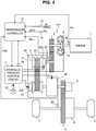
FIG. 1 is a schematic diagram of a vehicle including atransmission controller 12. A vehicle includes anengine 1 as a power source. The power of theengine 1 is transmitted to adriving wheel 7 via atorque converter 2, afirst gear train 3, atransmission 4, asecond gear train 5, and adifferential device 6 which configure a power train PT. Thesecond gear train 5 is equipped with aparking mechanism 8 for mechanically locking an output shaft of thetransmission 4 so as not to rotate at the time of parking. - The
torque converter 2 includes a lock-up clutch 2a. When the lock-up clutch 2a is engaged, slippage in thetorque converter 2 is eliminated so that a transmission efficiency of thetorque converter 2 is improved. Hereinafter, the lock-up clutch 2a is referred to as anLU clutch 2a. - The
transmission 4 is a continuously variable transmission including avariator 20. Thevariator 20 is a continuously variable transmission mechanism which includes aprimary pulley 21, asecondary pulley 22, and abelt 23 which is wound between thepulleys pulley 21 configures a driving side rotation element and thepulley 22 configures a driven side rotation element. - Each of the
pulleys pulley 21 includes ahydraulic cylinder 23a as a hydraulic cylinder and thepulley 22 includes ahydraulic cylinder 23b as a hydraulic cylinder. - When a hydraulic pressure which is supplied to the
hydraulic cylinders belt 23 and each of thepulleys variator 20 continuously changes. Thevariator 20 is a toroidal continuously variable transmission mechanism. - The
transmission 4 further includes a sub-transmission mechanism. Thesub-transmission mechanism 30 is a transmission mechanism of two forward gear positions and one reverse gear position and has a first speed and a second speed which has a low speed ratio than the first speed as forward gear positions. Thesub-transmission mechanism 30 is provided to be serial to thevariator 20 in a power transmission path from theengine 1 to thedriving wheel 7. - The
sub-transmission mechanism 30 may be directly connected to an output shaft of thevariator 20 as in the example or may be connected to the output shaft via a power transmission mechanism such as a shift or gear train. Alternately, thesub-transmission mechanism 30 may be connected to the input shaft of thevariator 20. - In the vehicle, an oil pump which is driven using a part of a power of the
engine 1, a hydraulicpressure control circuit 11 which adjusts a hydraulic pressure generated by the oil supplied from theoil pump 10 to supply the hydraulic pressure to individual parts of thetransmission 4, and atransmission controller 12 which controls the hydraulicpressure control circuit 11 are further provided. - The hydraulic
pressure control circuit 11 is configured by a plurality of flow passages and a plurality of hydraulic pressure control valves. The hydraulicpressure control circuit 11 controls the plurality of hydraulic pressure control valves based on a shift control signal from thetransmission controller 12 to switch a hydraulic pressure supply passage. Further, the hydraulicpressure control circuit 11 adjusts a necessary hydraulic pressure from a hydraulic pressure generated by the oil supplied from theoil pump 10 and supplies the adjusted hydraulic pressure to individual parts of thetransmission 4. By doing this, shift of thevariator 20, change of a gear position of thesub-transmission mechanism 30, and engagement/disengagement of theLU clutch 2a are performed. -
FIG. 2 is a schematic diagram of atransmission controller 12. Thetransmission controller 12 includes aCPU 121, amemory device 122 which is configured by an RAM and an ROM, aninput interface 123, anoutput interface 124, and abus 125 which connects the above-mentioned components. - For example, an output signal of an accelerator
pedal opening sensor 41 which detects an accelerator pedal opening APO representing an operation amount of an accelerator pedal, an output signal of arotation speed sensor 42 which detects an input-side rotation speed of thetransmission 4, an output signal of therotation speed sensor 43 which detects a rotation speed Nsec of thepulley 22, and an output signal of arotation speed sensor 44 which detects an output-side rotation speed of thetransmission 4 are input to theinput interface 123. - Specifically, the input-side rotation speed of the
transmission 4 is a rotation speed Npri of the input shaft of thetransmission 4, that is, a rotation speed Npri of thepulley 21. The output-side rotation speed of thetransmission 4 is specifically a rotation speed of the output shaft of the transmission, that is, a rotation speed of the output shaft of thesub-transmission mechanism 30. The input-side rotation speed of thetransmission 4 may be a rotation speed in a position where a gear train is sandwiched between thetransmission 4 and thetorque converter 2, such as a turbine rotation speed of thetorque converter 2. The output-side rotation speed of thetransmission 4 is the same as the above. - An output signal of a
vehicle speed sensor 45 which detects a vehicle speed VSP, an output signal of anoil temperature sensor 46 which detects an oil temperature TMP of thetransmission 4, an output signal of aninhibitor switch 47 which detects a position of a select lever, an output signal of arotation speed sensor 48 which detects a rotation speed Ne of theengine 1, an output signal of anOD switch 49 for increasing a shift coverage of thetransmission 4 to a speed ratio smaller than 1, an output signal of ahydraulic pressure sensor 50 which detects a hydraulic pressure supplied to theLU clutch 2a are input to theinput interface 123. A torque signal of an engine torque Te from anengine controller 51 which is provided in theengine 1 is also input to theinput interface 123. - A shift control program of the
transmission 4 and various maps used for the shift control program are stored in thememory device 122. TheCPU 121 reads and executes the shift control program stored in thememory device 122 and generates a shift control signal based on various signals input via the input interface 123.TheCPU 121 outputs the generated shift control signal to the hydraulicpressure control circuit 11 via theoutput interface 124. Various values which are used for arithmetic processings of theCPU 121 and arithmetic results of theCPU 121 are appropriately stored in the memory device. - However, in the
transmission 4, a longitudinal vibration may be generated at a PT resonance frequency Fpt which is a resonance frequency of the power train PT. When a stability of a speed ratio of thetransmission 4 with respect to a torque fluctuation of the power train is insufficient, it is considered that the torque fluctuation is coupled to the shift of thetransmission 4 to generate the longitudinal vibration. When the longitudinal vibration is generated, there is a fear that a drivability of a vehicle mounted with thetransmission 4 is deteriorated. - Therefore, the
transmission controller 12 performs the shift control which will be described below. Hereinafter, as the speed ratio of thetransmission 4, a speed ratio Ratio of thevariator 20 is used. The speed ratio Ratio is a generic name of the speed ratio of thevariator 20 including an actual speed ratio Ratio_A, a desired speed ratio Ratio_D, and a target speed ratio Ratio_T, which will be described below and includes at least any one of them. A primary pressure Ppri which is a hydraulic pressure supplied to thepulley 21 and a secondary pressure Psec which is a hydraulic pressure supplied to thepulley 22 are the same as the above. The speed ratio of thetransmission 4 may be a through speed ratio which is a total speed ratio of thevariator 20 and thesub-transmission mechanism 30. Hereinafter, thetransmission controller 12 is simply referred to as acontroller 12. -
FIG. 3 is a functional block diagram of acontroller 12 illustrating a main component of shift control. Thecontroller 12 has a hydraulic pressure controlFF control unit 131, a shift controlFB control unit 132, aphase advance compensator 133, an operatingregion determining unit 134, aswitch unit 135, and afilter unit 136. FF is an abbreviation of feedforward and FB is an abbreviation of feedback. - The target speed ratio Ratio_T of the
variator 20 is input to the hydraulic pressure controlFF control unit 131 and the shift controlFB control unit 132. The target speed ratio Ratio_T is a final desired shift control value having the speed ratio Ratio as a shift control value and is set in advance in accordance with a driving condition of the vehicle in a shift map. For example, the driving condition of the vehicle is a vehicle speed VSP and an accelerator pedal opening APO. - The hydraulic pressure
FF control unit 131 calculates an indicating pressure Psec_D for performing FF control on the secondary pressure Psec, based on the target speed ratio Ratio_T. The indicating pressure Psec_D is set to secure a fastening force of thebelt 23. The hydraulic pressure controlFF control unit 131 outputs the calculated indicating pressure Psec_D to the shift controlFB control unit 132. - The shift control
FB control unit 132 calculates an indicating pressure Ppri_D for performing FB control on the primary pressure Ppri, based on the actual speed ratio Ratio_A and the target speed ratio Ratio_T of thevariator 20, and the indicating pressure Psec_D. The indicating pressure Ppri_D is set as a transient desired primary pressure until the actual pressure Ppri_A of the primary pressure Ppri reaches a target primary pressure Ppri_T. The target primary pressure Ppri_T is a primary pressure Ppri corresponding to the target speed ratio Ratio_T. The shift controlFB control unit 132 outputs the calculated indicating pressure Ppri_D to thephase advance compensator 133 and theswitch unit 135. - The
phase advance compensator 133 performs phase advance compensation of the indicating pressure Ppri_D. Thephase advance compensator 133 may be, for example, configured by a filter having a time constant C (s). Thephase advance compensator 133 corresponds to a compensating unit. - The operating
region determining unit 134 determines whether an operating point M is in an advance compensating region R and outputs the determination result to theswitch unit 135. -
FIG. 4 is a view for explaining an advance compensation region R. InFIG. 4 , distribution of a plurality of operating points M is illustrated. The advance compensating region R is set in accordance with the rotation speed Npri and an input torque Tsec to thepulley 22. For example, the input torque Tsec may be calculated, for example, as a value obtained by multiplying the engine torque Te by the speed ratio set between theengine 1 and thepulley 22, that is, a gear ratio of thefirst gear train 3 and the speed ratio Ratio of the variator 20 in this embodiment. - The advance compensating region R includes a region R1 where the input torque Tsec is smaller than a predetermined torque Tsec1. The advance compensating region R further includes a region R2 where the input torque Tsec is equal to or larger than a predetermined torque Tsec1 and the rotation speed Npri is equal to or higher than a predetermined rotation speed Npri1.
- The larger the input torque Tsec is, the higher the predetermined rotation speed Npri1 is set. The predetermined rotation speed Npri1 is set to define a boundary B. The boundary B is a straight line in which the rotation speed Npri increases in proportion to the input torque Tsec.
- The predetermined torque Tsec1 and the predetermined rotation speed Npri1 are values for defining the input torque Tsec and the rotation speed Npri where the longitudinal vibration is generated and may be set in advance by experiments. The advance compensating region R includes an operating point in a case where the accelerator pedal is depressed with an opening corresponding to a road load, that is, a road load during coast traveling. The operating point M is not distributed in a region where the speed is lower than a rotation speed Npri corresponding to an idle rotation speed of the
engine 1. - The region partitioned from the advance compensating region R at the boundary B is a rebound region RX. The rebound region RX will be described below.
- However, when the speed ratio Ratio is higher than a predetermined
speed ratio Ratio 1, in other words, when the speed ratio Ratio is lower than the predeterminedspeed ratio Ratio 1, the advance compensating region R is set. The predeterminedspeed ratio Ratio 1 is a value for defining a speed ratio at which the longitudinal vibration is generated and, for example, is 1. The predeterminedspeed ratio Ratio 1 may be set in advance by experiments. - The advance compensating region R is further set for a case when a changing rate α of the speed ratio Ratio is smaller than a predetermined value α1. The predetermined value α1 is a value for determining a changing rate of the speed ratio Ratio at which the longitudinal vibration is generated and specifically, is set as a determining value for determining whether the speed ratio Ratio is in a normal state. The predetermined value α1 may be set in advance by experiments.
- The advance compensating region R is further set for a case when the LU clutch 2a is engaged.
- In the exemplary embodiment, the advance compensating region R is further set in accordance with the speed ratio Ratio, the changing rate α, and the engagement state of the LU clutch 2a so that the advance compensating region R is further set in accordance therewith. The operating points M is the same as the above.
- Therefore, as illustrated in
FIG. 3 , the operatingregion determining unit 134 determines whether the operating points M are in the advance compensating region R to also perform the determination. The processing performed by the operatingregion determining unit 134 will be described below with reference to a flowchart. - The
switch unit 135 selects any one of an indicatingpressure Ppri_D 1 which is an indicating pressure Ppri_D initially calculated by the shift controlFB control unit 132 and an indicating pressure Ppri_D2 which is an indicating pressure Ppri_D on which the phase advance compensation is performed by thephase advance compensator 133 as an indicating pressure Ppri_D in accordance with the determination result of the operatingregion determining unit 134. - When the operating point M is in the rebound region RX, that is, when the operating point M is not in the advance compensating region R, the
switch unit 135 selects the indicating pressure Ppri_D1 as the indicating pressure Ppri_D. - When the operating point M is in the advance compensating region R, the
switch unit 135 selects the indicating pressure Ppri_D2 as the indicating pressure Ppri_D. - The
switch unit 135 configures asetting unit 139 which sets the indicating pressure Ppri_D2 as an indicating pressure Ppri_D, in accordance with the rotation speed Npri, the input torque Tsec, the speed ratio Ratio, and the changing rate α, together with the operationregion determining unit 134. - An
actuator 111 controls the primary pressure Ppri and anactuator 112 controls the secondary pressure Psec. Theactuator 111 and theactuator 112 are specifically hydraulic pressure control valves and provided in the hydraulicpressure control circuit 111. - The indicating pressure Ppri_D which is selected from the
switch unit 135 is input to theactuator 111 and the indicating pressure Psec_D from the hydraulic pressure controlFF control unit 131 is input to theactuator 112. Theactuator 111 controls the primary pressure Ppri such that an actual pressure Ppri_A of the primary pressure Ppri becomes the indicating pressure Ppri_D and theactuator 112 controls the secondary pressure Ppri such that an actual pressure Psec_A of the secondary pressure Psec becomes the indicating pressure Psec_D. The actual pressure Ppri_A configures an actual shift control value and the indicating pressure Ppri_D configures a desired shift control value. - The actual pressure Ppri_A corresponding to the indicating pressure Ppri#D input to the variator 20 from the
actuator 111 and the actual pressure A corresponding to the indicating pressure Psec_D is input to the variator 20 from theactuator 112. As a result, the speed ratio Ratio is controlled such that the actual speed ratio Ratio_A becomes a desired speed ratio Ratio_D. The actual shift control value and the desired shift control value may be configured by an actual speed ratio Ratio_A and a desired speed ratio Ratio_D which have the speed ratio Ratio as a shift control value. - The fastening force of the
belt 23 is secured by the actual pressure Psec_A. Therefore, even though the input torque Tpri to thepulley 21 corresponding to the engine torque Te is input to thevariator 20, the slippage of thebelt 23 is not caused. - The actual speed ratio Ratio_A is input to the
engine 1. Further, the actual speed ratio Ratio_A is input to the shift controlFB control unit 132 via thefilter unit 136. A value calculated by thecontroller 12 may be applied as the actual speed ratio Ratio_A, based on the outputs of therotation speed sensor 4 and therotation speed sensor 43. - The
filter unit 136 performs the filter processing of the actual speed ratio Ratio_A. Thefilter unit 136 configures a high-order low pass filter. Thefilter unit 136, for example, has a plurality of first-order low pass filters. -
FIG. 5 is a flowchart of an example of a processing performed by thecontroller 12. Specifically, the processings of the flowchart are performed by the operatingregion determining unit 134. - In step S1, the
controller 12 determines whether the input torque Tsec is smaller than a predetermined torque Tsec1. When it is determined to be negative in step S1, the processing proceeds to step S2. - In step S2, the
controller 12 determines whether the rotation speed Npri is higher than a predetermined rotation speed Npri1. When it is determined to be positive in step S2, the processing proceeds to step S3. When it is determined to be positive in step S1, the processing also proceeds to step S3. - In step S3, the
controller 12 determines whether the speed ratio Ratio is higher than a predeterminedspeed ratio Ratio 1. The operatingregion determining unit 134, specifically, determines whether the actual speed ratio Ratio_A or the desired speed ratio Ratio_D is higher than a predeterminedspeed ratio Ratio 1. - Whether the speed ratio Ratio is higher than the predetermined speed ratio Ratio may be determined by determining whether OD switch 49 is off. The actual speed ratio Ratio_A and the desired speed ratio Ratio_D may be arithmetic values. When it is determined to be positive in step S3, the processing proceeds to step S4.
- In step S4, the
controller 12 determines whether the changing rate α is higher than a predetermined value α1. It may be determined whether the changing rate α is higher than a predetermined value α1 by determining whether the speed ratio Ratio is fixed by the driver's manipulation, for example, whether a manual range is selected by a select lever, based on the output of theinhibitor switch 47. When it is determined to be positive in step S4, the processing proceeds to step S5. - In step S5, the
controller 12 determines whether the LU clutch 2a is engaged. It may be determined whether theLU clutch 12 is engaged, based on the output of thehydraulic pressure sensor 50. - When it is determined to be positive in step S5, the processing proceeds to step S5 and the
controller 12 determines that the operating point M is in the advance compensating region R. - When it is determined to be negative in step S5, the processing proceeds to step S7 and the
controller 12 determines that the operating point M is not in an advance compensating region R. When it is determined to be negative in steps S2 to S4, the same is applied. - In other words, in step S7, it is determined that the operating point M is in the rebound region R. In the rebound region Rx, when the indicating pressure Ppri_D2 is set as an indicating pressure Ppri_D, the vibration of the actual pressure Ppri_A may be caused as a result of the vibration of the indicating pressure Ppri_D.
- Therefore, when the operating point M is not in the advance compensating region R, by setting the indicating pressure Ppri_D1 as the indicating pressure Ppri_D, not only the stability of the speed ratio Ratio is not unnecessarily increased, but also the vibration of the actual pressure Ppri_A is prevented.
- Next, a main operating effect of the
controller 12 will be described. - The
controller 12 configures a control device of a continuously variable transmission which performs shift control of thetransmission 4 such that the actual pressure Ppri_A becomes an indicating pressure Ppri_D. Thecontroller 12 has aphase advance compensator 133 which performs advance compensation of the indicating pressure Ppri_D and asetting unit 139 which sets an indicating pressure Ppri_D2 at which the advance compensation is performed by thephase advance compensator 133 as an indicting pressure Ppri_D in accordance with the rotation speed Npri, the input torque Tsec, the speed ratio Ratio, and the changing rate α. - By the
controller 12 with the above-described configuration, it is possible to set the indicating pressure Ppri_D2 in the region where the longitudinal vibration is generated, as the indicating pressure Ppri_D. Therefore, it is possible to improve the stability of the speed ratio Ratio by the phase advance compensation of the indicating pressure Ppri_D as necessary and thus it is possible to appropriately improve the longitudinal vibration of thetransmission 4 by converging the longitudinal vibration. - Further, by the
controller 12 with the above-described configuration, the stability of the speed ratio Ratio is increased by the phase advance compensation so that the control responsiveness of the speed ratio Ratio is also improved. Further, by thecontroller 12 with the above-described configuration, the stability of the speed ratio Ratio is increased as necessary so that when it is not necessary to increase the stability of the speed ratio Ratio, the vibration of the actual pressure Ppri_A may be suppressed. - The
controller 12 further includes afilter unit 136 which performs the filter processing of the actual speed ratio Ratio_A and configures a higher-order low pass filter. - By the
controller 12 with the above-described configuration, as compared with a case when a slight delay occurs in a region below a frequency to be eliminated using the first-order low pass filter, the delay is improved and thus, the phase of the indicating pressure Ppri_D may be further advanced. - When the operating point M is in the advance compensating region R, the
setting unit 139 in thecontroller 12 sets the indicating pressure Ppri_D2 as the indicating pressure Ppri_D. - By the
controller 12 with the above-described configuration, among regions in accordance with the rotation speed Npri and the input torque Tsec, a region where the longitudinal vibration is generated is considered as an advance compensating region R and the stability of the speed ratio Ratio is increased so that the longitudinal vibration may be appropriately improved. - In the
controller 12, the advance compensating region R includes a region R1 where the input torque Tsec is smaller than a predetermined torque Tsec1. By thecontroller 12 with the above-described configuration, it is possible to appropriately set the advance compensating region R. - In the
controller 12, the advance compensating region R further includes a region R2 where the input torque Tsec is equal to or larger than a predetermined torque Tsec1 and the rotation speed Npri is equal to or higher than a predetermined rotation speed Npri1. The larger the input torque Tsec is, the higher the predetermined rotation speed Npri1 is set. By thecontroller 12 with the above-described configuration, it is possible to further appropriately set the advance compensating region R. - In the
controller 12, when the speed ratio Ratio is higher than the predeterminedspeed ratio Ratio 1, thesetting unit 139 sets the indicating pressure Ppri_D2 as the indicating pressure Ppri_D. By thecontroller 12 with the above-described configuration, the longitudinal vibration may be appropriately improved in accordance with the speed ratio Ratio. - In the
controller 12, when the changing rate α is lower than the predetermined value α1, thesetting unit 139 sets the indicating pressure Ppri_D2 as the indicating pressure Ppri_D. By thecontroller 12 with the above-described configuration, the longitudinal vibration may be appropriately improved in accordance with the changing rate α. - In the exemplary embodiment, the
transmission 4 may input the power via atorque converter 2 with the LU clutch 2a. When the LU clutch 2a is engaged, thecontroller 12 further sets the indicating pressure Ppri_D2 as the indicating pressure Ppri_D. By thecontroller 12 with the above-described configuration, the longitudinal vibration may be appropriately improved in accordance with the state of the LU clutch 2a. - Although the embodiment of the present invention has been described above, the above-mentioned embodiment merely shows a part of the application example of the present invention, but the technical scope of the present invention is not limited to the specific configuration of the above embodiment.
- In the above-described embodiment, it has been described that the
setting unit 139 sets the indicating pressure Ppri_D2 as the indicating pressure Ppri_D according to all of four parameters of the rotation speed Npri, the input torque Tsec, the speed ratio Ratio, and the change rate α. - However, the
setting unit 139 may be configured to set the indicating pressure Ppri_D2 as the indicating pressure Ppri_D in accordance with at least one parameter of the input torque Tsec, the speed ratio Ratio, or the change rate α. Also in this case, the longitudinal vibration may be appropriately improved by appropriately increasing the stability of the speed ratio Ratio in relation to the parameter. - In the above-described exemplary embodiment, it has been described that the advance compensating region R is further set in accordance with the speed ratio Ratio, the changing rate α, and the engagement state of the LU clutch 2a so that the advance compensating region R is further set in accordance therewith.
- However, the
controller 12, for example, does not determine the speed ratio Ratio, the changing rate α, and the engagement state of the LU clutch 2a when it is determined whether the operating point M is in the advance compensating region, but may be separately determine the speed ratio Ratio, the changing rate α, and the engagement state of the LU clutch 2a. - In the above-described embodiment, it has been described that the operating
region determining unit 134 and theswitch unit 135 configure thesetting unit 139. However, it may be understood that thesetting unit 139 is configured by theswitch unit 135 which selects the indicating pressure Ppri_D according to the determining result of the operatingregion determining unit 134. - In the above-described embodiment, it has been described that the
controller 12 is configured as a control device of the continuously variable transmission. However, the control device of the continuously variable transmission may be implemented by a plurality of controllers. - This application claims the priority based on Japanese Patent Application No.
2016-045497
Claims (9)
- A control device of a continuously variable transmission which performs shift control of the continuously variable transmission such that an actual shift control value becomes a desired shift control value, the control device comprising:an advance compensating unit configured to perform advance compensation of the desired shift control value; anda setting unit configured to set a compensated desired shift control value on which the advance compensation is performed by the advance compensating unit as the desired shift control value, in accordance with at least one of an input-side rotation speed of the continuously variable transmission, an input torque to a driven-side rotation element of the continuously variable transmission, a speed ratio of the continuously variable transmission, or a changing rate of the speed ratio.
- The control device of a continuously variable transmission according to claim 1, further comprising a filter unit configured to perform a filter processing of the actual shift control value and form a higher-order low pass filter.
- The control device of a continuously variable transmission according to claim 1 or 2, wherein when an operating point in accordance with the input-side rotation speed and the input torque is in an advance compensating region set in accordance with the input-side rotation speed and the input torque, the setting unit sets the compensated desired shift control value as the desired shift control value.
- The control device of a continuously variable transmission according to claim 3, wherein the advance compensating region includes a region where the input torque is smaller than a predetermined torque.
- The control device of a continuously variable transmission according to claim 4, wherein the advance compensating region further includes a region where the input torque is equal to or higher than the predetermined torque and the input-side rotation speed is equal to or higher than a predetermined rotation speed, and the predetermined rotation speed is set to be higher as the input torque becomes higher.
- The control device of a continuously variable transmission according to claim 1 or 2, wherein when the speed ratio is higher than a predetermined speed ratio, the setting unit sets the compensated desired shift control value as the desired shift control value.
- The control device of a continuously variable transmission according to claim 1 or 2, wherein when the changing rate is lower than a predetermined value, the setting unit sets the compensated desired shift control value as the desired shift control value.
- The control device of a continuously variable transmission according to claim 1 or 2, wherein the continuously variable transmission receives a power input via a torque converter with a lock-up clutch, and when the lock-up clutch is engaged, the setting unit sets the compensated desired shift control value as the desired shift control value.
- A control method of a continuously variable transmission which performs shift control of the continuously variable transmission such that an actual shift control value becomes a desired shift control value, the control method comprising:performing advance compensation of the desired shift control value; andsetting a compensated desired shift control value on which the advance compensation is performed as the desired shift control value, in accordance with at least one of a rotation speed of an input side of the continuously variable transmission, an input torque to a driven-side rotation element of the continuously variable transmission, a speed ratio of the continuously variable transmission, or a changing rate of the speed ratio.
Applications Claiming Priority (2)
| Application Number | Priority Date | Filing Date | Title |
|---|---|---|---|
| JP2016045497A JP6666756B2 (en) | 2016-03-09 | 2016-03-09 | Control device for continuously variable transmission and control method for continuously variable transmission |
| PCT/JP2017/007380 WO2017154632A1 (en) | 2016-03-09 | 2017-02-27 | Control device for continuously variable transmission and control method for continuously variable transmission |
Publications (2)
| Publication Number | Publication Date |
|---|---|
| EP3428484A1 true EP3428484A1 (en) | 2019-01-16 |
| EP3428484A4 EP3428484A4 (en) | 2019-03-20 |
Family
ID=59790372
Family Applications (1)
| Application Number | Title | Priority Date | Filing Date |
|---|---|---|---|
| EP17762972.2A Withdrawn EP3428484A4 (en) | 2016-03-09 | 2017-02-27 | Control device for continuously variable transmission and control method for continuously variable transmission |
Country Status (6)
| Country | Link |
|---|---|
| US (1) | US10731757B2 (en) |
| EP (1) | EP3428484A4 (en) |
| JP (1) | JP6666756B2 (en) |
| KR (1) | KR102104066B1 (en) |
| CN (1) | CN108779846B (en) |
| WO (1) | WO2017154632A1 (en) |
Families Citing this family (8)
| Publication number | Priority date | Publication date | Assignee | Title |
|---|---|---|---|---|
| JP6772553B2 (en) * | 2016-05-25 | 2020-10-21 | 日産自動車株式会社 | Control method of continuously variable transmission |
| JP6887734B2 (en) * | 2017-09-15 | 2021-06-16 | ジヤトコ株式会社 | Control device for continuously variable transmission |
| CN111094804B (en) * | 2017-09-15 | 2021-08-17 | 加特可株式会社 | Control device and control method of continuously variable transmission |
| US11067171B2 (en) | 2017-09-15 | 2021-07-20 | Jatco Ltd. | Control device and control method for continuously variable transmission |
| JP6847537B2 (en) * | 2017-09-15 | 2021-03-24 | ジヤトコ株式会社 | Control device for continuously variable transmission |
| WO2019054354A1 (en) * | 2017-09-15 | 2019-03-21 | ジヤトコ株式会社 | Control device and control method for continuously variable transmission |
| JP6896343B2 (en) * | 2017-09-15 | 2021-06-30 | ジヤトコ株式会社 | Control device for continuously variable transmission |
| CN111094803B (en) * | 2017-09-15 | 2021-08-17 | 加特可株式会社 | Control device and control method of continuously variable transmission |
Family Cites Families (9)
| Publication number | Priority date | Publication date | Assignee | Title |
|---|---|---|---|---|
| JP3473363B2 (en) | 1997-02-27 | 2003-12-02 | 株式会社デンソー | System control unit |
| JP3942005B2 (en) * | 2000-09-29 | 2007-07-11 | ジヤトコ株式会社 | Shift control device for continuously variable transmission |
| JP2002124047A (en) | 2000-10-11 | 2002-04-26 | Sony Corp | Magnetic disk drive |
| JP2005069455A (en) * | 2003-08-28 | 2005-03-17 | Nissan Motor Co Ltd | Gear ratio control device for continuously variable transmission |
| JP4849870B2 (en) * | 2005-10-31 | 2012-01-11 | ジヤトコ株式会社 | Control device for continuously variable transmission for automobile |
| CN102165227B (en) * | 2008-09-26 | 2015-09-30 | 罗伯特·博世有限公司 | Control the method for the normal force in the rubbing contact of stepless speed variator |
| JP2011207240A (en) * | 2010-03-26 | 2011-10-20 | Toyota Motor Corp | Vehicle control system |
| WO2014010705A1 (en) | 2012-07-12 | 2014-01-16 | 日産自動車株式会社 | Control device for vehicle |
| WO2014129060A1 (en) * | 2013-02-21 | 2014-08-28 | 本田技研工業株式会社 | Gear change control device |
-
2016
- 2016-03-09 JP JP2016045497A patent/JP6666756B2/en active Active
-
2017
- 2017-02-27 WO PCT/JP2017/007380 patent/WO2017154632A1/en not_active Ceased
- 2017-02-27 EP EP17762972.2A patent/EP3428484A4/en not_active Withdrawn
- 2017-02-27 CN CN201780016082.0A patent/CN108779846B/en active Active
- 2017-02-27 US US16/083,431 patent/US10731757B2/en active Active
- 2017-02-27 KR KR1020187028483A patent/KR102104066B1/en not_active Expired - Fee Related
Also Published As
| Publication number | Publication date |
|---|---|
| US10731757B2 (en) | 2020-08-04 |
| US20190078685A1 (en) | 2019-03-14 |
| KR102104066B1 (en) | 2020-04-23 |
| CN108779846B (en) | 2020-04-28 |
| KR20180114213A (en) | 2018-10-17 |
| WO2017154632A1 (en) | 2017-09-14 |
| JP6666756B2 (en) | 2020-03-18 |
| JP2017160982A (en) | 2017-09-14 |
| CN108779846A (en) | 2018-11-09 |
| EP3428484A4 (en) | 2019-03-20 |
Similar Documents
| Publication | Publication Date | Title |
|---|---|---|
| US10731757B2 (en) | Control device of continuously variable transmission and control method of continuously variable transmission | |
| EP3348871A1 (en) | Device and method for hydraulically controlling continuously variable transmission for vehicle | |
| US10989301B2 (en) | Control device for continuously variable transmission and control method for continuously variable transmission | |
| US10837551B2 (en) | Control method of continuously variable transmissions | |
| US10871224B2 (en) | Control device for continuously variable transmission and control method for continuously variable transmission | |
| JP6772553B2 (en) | Control method of continuously variable transmission | |
| CN111094803B (en) | Control device and control method of continuously variable transmission | |
| US11067172B2 (en) | Control device and control method for continuously variable transmission | |
| US11067171B2 (en) | Control device and control method for continuously variable transmission | |
| WO2017159268A1 (en) | Control device for continuously variable transmission and control method for continuously variable transmission |
Legal Events
| Date | Code | Title | Description |
|---|---|---|---|
| STAA | Information on the status of an ep patent application or granted ep patent |
Free format text: STATUS: THE INTERNATIONAL PUBLICATION HAS BEEN MADE |
|
| PUAI | Public reference made under article 153(3) epc to a published international application that has entered the european phase |
Free format text: ORIGINAL CODE: 0009012 |
|
| STAA | Information on the status of an ep patent application or granted ep patent |
Free format text: STATUS: REQUEST FOR EXAMINATION WAS MADE |
|
| 17P | Request for examination filed |
Effective date: 20180911 |
|
| AK | Designated contracting states |
Kind code of ref document: A1 Designated state(s): AL AT BE BG CH CY CZ DE DK EE ES FI FR GB GR HR HU IE IS IT LI LT LU LV MC MK MT NL NO PL PT RO RS SE SI SK SM TR |
|
| AX | Request for extension of the european patent |
Extension state: BA ME |
|
| STAA | Information on the status of an ep patent application or granted ep patent |
Free format text: STATUS: THE APPLICATION HAS BEEN WITHDRAWN |
|
| A4 | Supplementary search report drawn up and despatched |
Effective date: 20190218 |
|
| RIC1 | Information provided on ipc code assigned before grant |
Ipc: F16H 61/70 20060101ALI20190212BHEP Ipc: F16H 61/66 20060101ALI20190212BHEP Ipc: F16H 61/662 20060101ALI20190212BHEP Ipc: F16H 59/38 20060101ALI20190212BHEP Ipc: F16H 61/02 20060101AFI20190212BHEP |
|
| 18W | Application withdrawn |
Effective date: 20190311 |