EP3428471A1 - Shock-absorbing stopper - Google Patents
Shock-absorbing stopper Download PDFInfo
- Publication number
- EP3428471A1 EP3428471A1 EP17763196.7A EP17763196A EP3428471A1 EP 3428471 A1 EP3428471 A1 EP 3428471A1 EP 17763196 A EP17763196 A EP 17763196A EP 3428471 A1 EP3428471 A1 EP 3428471A1
- Authority
- EP
- European Patent Office
- Prior art keywords
- movable
- diameter portion
- large diameter
- hollow
- fixed
- Prior art date
- Legal status (The legal status is an assumption and is not a legal conclusion. Google has not performed a legal analysis and makes no representation as to the accuracy of the status listed.)
- Granted
Links
Images

Classifications
-
- B—PERFORMING OPERATIONS; TRANSPORTING
- B62—LAND VEHICLES FOR TRAVELLING OTHERWISE THAN ON RAILS
- B62D—MOTOR VEHICLES; TRAILERS
- B62D1/00—Steering controls, i.e. means for initiating a change of direction of the vehicle
- B62D1/02—Steering controls, i.e. means for initiating a change of direction of the vehicle vehicle-mounted
- B62D1/16—Steering columns
- B62D1/18—Steering columns yieldable or adjustable, e.g. tiltable
- B62D1/19—Steering columns yieldable or adjustable, e.g. tiltable incorporating energy-absorbing arrangements, e.g. by being yieldable or collapsible
- B62D1/195—Yieldable supports for the steering column
-
- B—PERFORMING OPERATIONS; TRANSPORTING
- B62—LAND VEHICLES FOR TRAVELLING OTHERWISE THAN ON RAILS
- B62D—MOTOR VEHICLES; TRAILERS
- B62D3/00—Steering gears
- B62D3/02—Steering gears mechanical
- B62D3/12—Steering gears mechanical of rack-and-pinion type
-
- F—MECHANICAL ENGINEERING; LIGHTING; HEATING; WEAPONS; BLASTING
- F16—ENGINEERING ELEMENTS AND UNITS; GENERAL MEASURES FOR PRODUCING AND MAINTAINING EFFECTIVE FUNCTIONING OF MACHINES OR INSTALLATIONS; THERMAL INSULATION IN GENERAL
- F16F—SPRINGS; SHOCK-ABSORBERS; MEANS FOR DAMPING VIBRATION
- F16F1/00—Springs
- F16F1/36—Springs made of rubber or other material having high internal friction, e.g. thermoplastic elastomers
- F16F1/373—Springs made of rubber or other material having high internal friction, e.g. thermoplastic elastomers characterised by having a particular shape
- F16F1/3732—Springs made of rubber or other material having high internal friction, e.g. thermoplastic elastomers characterised by having a particular shape having an annular or the like shape, e.g. grommet-type resilient mountings
-
- F—MECHANICAL ENGINEERING; LIGHTING; HEATING; WEAPONS; BLASTING
- F16—ENGINEERING ELEMENTS AND UNITS; GENERAL MEASURES FOR PRODUCING AND MAINTAINING EFFECTIVE FUNCTIONING OF MACHINES OR INSTALLATIONS; THERMAL INSULATION IN GENERAL
- F16F—SPRINGS; SHOCK-ABSORBERS; MEANS FOR DAMPING VIBRATION
- F16F7/00—Vibration-dampers; Shock-absorbers
-
- F—MECHANICAL ENGINEERING; LIGHTING; HEATING; WEAPONS; BLASTING
- F16—ENGINEERING ELEMENTS AND UNITS; GENERAL MEASURES FOR PRODUCING AND MAINTAINING EFFECTIVE FUNCTIONING OF MACHINES OR INSTALLATIONS; THERMAL INSULATION IN GENERAL
- F16F—SPRINGS; SHOCK-ABSORBERS; MEANS FOR DAMPING VIBRATION
- F16F2234/00—Shape
- F16F2234/02—Shape cylindrical
-
- F—MECHANICAL ENGINEERING; LIGHTING; HEATING; WEAPONS; BLASTING
- F16—ENGINEERING ELEMENTS AND UNITS; GENERAL MEASURES FOR PRODUCING AND MAINTAINING EFFECTIVE FUNCTIONING OF MACHINES OR INSTALLATIONS; THERMAL INSULATION IN GENERAL
- F16F—SPRINGS; SHOCK-ABSORBERS; MEANS FOR DAMPING VIBRATION
- F16F2236/00—Mode of stressing of basic spring or damper elements or devices incorporating such elements
- F16F2236/04—Compression
Definitions
- the present invention relates to a shock-absorbing stopper having both a shock absorbing function and a stopper function.
- the shock-absorbing stopper of the present invention is installed in a steering device and the like in the field of automobile equipment, for example, or used in the field of industrial equipment and the like.
- the shock-absorbing stopper 51 has a cylindrical elastic body 52, in which a fixed-side metal fitting 53 is connected to one end portion (upper end portion in the figure) of the elastic body 52 and a movable-side metal fitting 54 is connected to the other end portion (lower end portion in the figure) thereof.
- the one end portion (hereinafter sometimes also referred to as a fixed-side end portion 55) to which the fixed-side metal fitting 53 is connected is fixed to a housing 61 which is a mating component.
- a shaft which is an actuating component collides with the other end portion (hereinafter sometimes also referred to as a movable-side end portion 56) to which the movable-side metal fitting 54 is connected, so that the other end portion is displaced together with the shaft.
- Patent Document 1 Japanese Patent No. 4620291
- the stopper 51 is sectioned into three portions of a small diameter portion 51A formed by the hollow 57, a fixed-side large diameter portion 51B located closer to the fixed side relative to the hollow 57, and a movable-side large diameter portion 51C located closer to the movable side relative to the hollow 57.
- an axial width w 4 of the elastic body 52 obtained by subtracting an axial width (thickness) w 3 of the movable-side metal fitting 54 from the axial width w 2 of the movable-side large diameter portion 51C is set considerably large.
- a shock-absorbing stopper capable of preventing an elastic body from contacting a mating component, such as a housing, to cause sliding wear as much as possible in a structure where a hollow is provided in the outer peripheral surface of the elastic body.
- a shock-absorbing stopper of the present invention has a cylindrical elastic body, to one end portion of which a fixed-side metal fitting is connected and to the other end portion of which a movable-side metal fitting is connected and which has an annular hollow in the outer peripheral surface of the cylindrical elastic body, in which the shock-absorbing stopper is sectioned into three portions by the hollow of a small diameter portion formed by the hollow, a fixed-side large diameter portion located closer to the fixed side relative to the hollow, and a movable-side large diameter portion located closer to the movable side relative to the hollow, the outer diameter dimension of the movable-side large diameter portion is set smaller than the outer diameter dimension of the fixed-side large diameter portion, and the axial width of the movable-side large diameter portion is set smaller than the axial width of the fixed-side large diameter portion.
- a portion where the sliding wear is likely to occur is the outer peripheral surface of the movable-side large diameter portion located closer to the movable side relative to the hollow among the sectioned three portions.
- the present invention is configured so that the outer diameter dimension of the movable-side large diameter portion is set smaller than the outer diameter dimension of the fixed-side large diameter portion, and thus a relatively large radial gap is set between the movable-side large diameter portion and the mating component, such as a housing.
- the axial width of the movable-side large diameter portion is set smaller than the axial width of the movable-side large diameter portion, and thus, even when the movable-side large diameter portion is swollen and deformed, the swollen and deformed amount is suppressed. Accordingly, the radial gap is set large by the former and the swollen and deformed amount is suppressed by the latter, and therefore the movable-side large diameter portion does not contact the housing even when the movable-side large diameter portion is swollen and deformed or, even when the movable-side large diameter portion contacts the housing, the contact surface pressure or the contact width can be reduced. Therefore, the sliding wear is hard to occur in the movable-side large diameter portion.
- the present invention can prevent an elastic body from contacting a mating component, such as a housing, to cause sliding wear as much as possible in a structure where a hollow is provided in the outer peripheral surface of the elastic body.
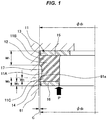
- a shock-absorbing stopper 11 has a cylindrical elastic body 12 containing a predetermined rubber-like elastic body, in which an annular fixed-side metal fitting 13 is connected to one axial end portion (upper end portion in the figure) of the cylindrical elastic body 12 and an annular movable-side metal fitting 14 is connected to the other axial end portion (lower end portion in the figure) thereof.
- the one end portion (hereinafter sometimes also referred to as a fixed-side end portion 15) to which the fixed-side metal fitting 13 is connected is fixed to the housing 61 which is a mating component.
- a shaft which is an actuating component collides with the other end portion (hereinafter sometimes also referred to as a movable-side end portion 16) to which the movable-side metal fitting 14 is connected, so that the other end portion is displaced together with the shaft.
- An annular hollow 17 is provided in the outer peripheral surface of the elastic body 12. Moreover, due to the fact that the annular hollow 17 is provided in the outer peripheral surface of the elastic body 12 as described above, the shock-absorbing stopper 11 is sectioned into three portions, that is, a small diameter portion 11A formed by the hollow 17, and having an outer peripheral surface of a relatively small diameter, a fixed-side large diameter portion 11B located closer to the fixed side relative to the hollow 17 and having an outer peripheral surface of a relatively large diameter, and a movable-side large diameter portion 11C located closer to the movable side relative to the hollow 17 and having an outer peripheral surface of a relatively large diameter.
- the outer diameter dimension ⁇ d 2 of the movable-side large diameter portion 11C is set smaller than the outer diameter dimension ⁇ d 1 of the fixed-side large diameter portion 11B ( ⁇ d 1 > ⁇ d 2 ) and the axial width w 2 of the movable-side large diameter portion 11C is set smaller than the axial width w 1 of the fixed-side large diameter portion 11B (w 1 > w 2 ) among the sectioned three portions.
- the outer diameter dimension ⁇ d 2 of the movable-side large diameter portion 11C is set smaller than the outer diameter dimension ⁇ d 1 of the fixed-side large diameter portion 11B ( ⁇ d 1 > ⁇ d 2 ) as described above, and therefore a relatively large radial gap c is set between the movable-side large diameter portion 11C and the inner peripheral surface 61a of the housing 61.
- the axial width w 2 of the movable-side large diameter portion 11C is set smaller than the axial width w 1 of the fixed-side large diameter portion 11B (w 1 > w 2 ) as described above, and therefore, even when the movable-side large diameter portion 11C is swollen and deformed, the swollen and deformed amount can be suppressed.
- the radial gap c is set large due to ⁇ d 1 > ⁇ d 2 of the former and the swollen and deformed amount is suppressed due to w 1 > w 2 of the latter, and therefore the movable-side large diameter portion 11C does not contact the housing 61 even when the movable-side large diameter portion 11C is swollen and deformed or, even when the movable-side large diameter portion 11C contacts the housing 61, the contact surface pressure and the contact width can be reduced. Therefore, the sliding wear is hard to occur in the movable-side large diameter portion 11C.
- the first embodiment described above is configured so that the axial width w 2 of the movable-side large diameter portion 11C is the sum of the axial width (thickness) w 3 of the movable-side metal fitting 14 and the axial width w 4 between the hollow 17 in the elastic body 12 and the movable-side metal fitting 14, and as the axial width w 2 of the movable-side large diameter portion 11C becomes small, the axial width w 4 between the hollow 17 in the elastic body 12 and the movable-side metal fitting 14 also becomes small in connection therewith.
- the axial width w 2 of the movable-side large diameter portion 11C may be set only by the axial width (thickness) w 3 of the movable-side metal fitting 14. In this case, the axial width w 4 between the hollow 17 in the elastic body 12 and the movable-side metal fitting 14 is set to zero.
- the axial width w 2 of the movable-side large diameter portion 11C is set only by the axial width (thickness) w 3 of the movable-side metal fitting 14 and the axial width between the hollow 17 in the elastic body 12 and the movable-side metal fitting 14 is set to zero from such a viewpoint.
- the position of the hollow 17 further shifts to the movable-side as compared with the first embodiment, and therefore the elastic body 12 does not contact the housing 61 even when the elastic body 12 is swollen and deformed or, even when the elastic body 12 contacts the housing 61, the contact surface pressure and the contact width can be further reduced. Therefore, the sliding wear is harder to occur in the elastic body 12.
- the shape of the fixed-side metal fitting 13 or the movable-side metal fitting 14 is not particularly limited and may be a ring having a rectangular cross section or a ring having an L-shaped cross section as illustrated in FIG. 2 or the like besides the plate-like ring as illustrated in FIG. 1
Landscapes
- Engineering & Computer Science (AREA)
- General Engineering & Computer Science (AREA)
- Mechanical Engineering (AREA)
- Chemical & Material Sciences (AREA)
- Combustion & Propulsion (AREA)
- Transportation (AREA)
- Vibration Dampers (AREA)
- Springs (AREA)
- Drawers Of Furniture (AREA)
- Braking Arrangements (AREA)
- Vibration Prevention Devices (AREA)
Abstract
Description
- The present invention relates to a shock-absorbing stopper having both a shock absorbing function and a stopper function. The shock-absorbing stopper of the present invention is installed in a steering device and the like in the field of automobile equipment, for example, or used in the field of industrial equipment and the like.
- Heretofore, a shock-
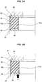
absorbing stopper 51 illustrated inFIG. 3A is known. The shock-absorbingstopper 51 has a cylindricalelastic body 52, in which a fixed-side metal fitting 53 is connected to one end portion (upper end portion in the figure) of theelastic body 52 and a movable-side metal fitting 54 is connected to the other end portion (lower end portion in the figure) thereof. The one end portion (hereinafter sometimes also referred to as a fixed-side end portion 55) to which the fixed-side metal fitting 53 is connected is fixed to ahousing 61 which is a mating component. A shaft (not illustrated) which is an actuating component collides with the other end portion (hereinafter sometimes also referred to as a movable-side end portion 56) to which the movable-side metal fitting 54 is connected, so that the other end portion is displaced together with the shaft. - Patent Document 1: Japanese Patent No.
4620291 - When the shaft collides with the movable-
side end portion 56, so that a load P is applied as illustrated inFIG. 3B , the movable-side end portion 56 is displaced in a direction approaching the fixed-side end portion 55, so that theelastic body 52 is compressed. Therefore, the shock absorbing function by the compression and deformation of theelastic body 52 is exhibited. An outerperipheral surface 52a of the compressedelastic body 52 is radially outward swollen and deformed to contact an innerperipheral surface 61a of thehousing 61. The movable-side end portion 56 is continuously displaced also after theelastic body 52 contacts thehousing 61, and therefore theelastic body 52 slides in a contact portion with thehousing 61. Therefore, wear due to the sliding occurs, so that the performance of thestopper 51 decreases. - In order to suppress the sliding wear of the
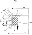
elastic body 52, it is considered to provide anannular hollow 57 in the outer peripheral surface of theelastic body 52 as illustrated in a reference example ofFIG. 4 to thereby reduce the swollen and deformed amount when compressed to reduce the contact surface pressure to thehousing 61. - However, when the hollow 57 is provided in the outer peripheral surface of the
elastic body 52 as described above, the following points need to be taken into consideration. - More specifically, when the hollow 57 is provided in the outer peripheral surface of the
elastic body 52 as described above, thestopper 51 is sectioned into three portions of asmall diameter portion 51A formed by the hollow 57, a fixed-sidelarge diameter portion 51B located closer to the fixed side relative to the hollow 57, and a movable-sidelarge diameter portion 51C located closer to the movable side relative to the hollow 57. - In this case, when an outer diameter dimension φd1 of the fixed-side
large diameter portion 51B and an outer diameter dimension φd2 of the movable-sidelarge diameter portion 51C are equally set (φd1 = φd2) and an axial width w1 of the fixed-sidelarge diameter portion 51B and an axial width w2 of the movable-sidelarge diameter portion 51C are equally set (w1 = w2) so as to equalize the dimensions, there is a possibility that the following inconvenience may occur. - More specifically, according to the above-described setting (φd1 = φd2 and w1 = w2), an axial width w4 of the
elastic body 52 obtained by subtracting an axial width (thickness) w3 of the movable-side metal fitting 54 from the axial width w2 of the movable-sidelarge diameter portion 51C is set considerably large. - Therefore, when the shaft collides with the movable-
side end portion 56, so that the load P is applied, whereby the movable-side end portion 56 is displaced in a direction approaching the fixed-side end portion 55, so that theelastic body 52 is compressed, the outer peripheral surface of theelastic body 52 is radially outward swollen and deformed in the movable-sidelarge diameter portion 51C to contact the innerperipheral surface 61a of thehousing 61. Then, the movable-side end portion 56 is continuously displaced also after theelastic body 52 contacts thehousing 61 as described above, and therefore theelastic body 52 slides in the movable-sidelarge diameter portion 51C, so that the wear due to the sliding occurs. This phenomenon is likely to occur particularly when the axial displacement amount of the movable-side end portion 56 to the fixed-side end portion 55 is excessively large (larger than expected). - In view of the above-described points, it is an object of the present invention to provide a shock-absorbing stopper capable of preventing an elastic body from contacting a mating component, such as a housing, to cause sliding wear as much as possible in a structure where a hollow is provided in the outer peripheral surface of the elastic body.
- In order to achieve the above-described object, a shock-absorbing stopper of the present invention has a cylindrical elastic body, to one end portion of which a fixed-side metal fitting is connected and to the other end portion of which a movable-side metal fitting is connected and which has an annular hollow in the outer peripheral surface of the cylindrical elastic body, in which the shock-absorbing stopper is sectioned into three portions by the hollow of a small diameter portion formed by the hollow, a fixed-side large diameter portion located closer to the fixed side relative to the hollow, and a movable-side large diameter portion located closer to the movable side relative to the hollow, the outer diameter dimension of the movable-side large diameter portion is set smaller than the outer diameter dimension of the fixed-side large diameter portion, and the axial width of the movable-side large diameter portion is set smaller than the axial width of the fixed-side large diameter portion.
- In the structure where the hollow is provided in the outer peripheral surface of the elastic body, a portion where the sliding wear is likely to occur is the outer peripheral surface of the movable-side large diameter portion located closer to the movable side relative to the hollow among the sectioned three portions. Then, the present invention is configured so that the outer diameter dimension of the movable-side large diameter portion is set smaller than the outer diameter dimension of the fixed-side large diameter portion, and thus a relatively large radial gap is set between the movable-side large diameter portion and the mating component, such as a housing. Moreover, the axial width of the movable-side large diameter portion is set smaller than the axial width of the movable-side large diameter portion, and thus, even when the movable-side large diameter portion is swollen and deformed, the swollen and deformed amount is suppressed. Accordingly, the radial gap is set large by the former and the swollen and deformed amount is suppressed by the latter, and therefore the movable-side large diameter portion does not contact the housing even when the movable-side large diameter portion is swollen and deformed or, even when the movable-side large diameter portion contacts the housing, the contact surface pressure or the contact width can be reduced. Therefore, the sliding wear is hard to occur in the movable-side large diameter portion.
- The present invention can prevent an elastic body from contacting a mating component, such as a housing, to cause sliding wear as much as possible in a structure where a hollow is provided in the outer peripheral surface of the elastic body.
-
-
FIG. 1 is a cross-sectional view of a principal portion of a shock-absorbing stopper according to a first embodiment of the present invention. -
FIG. 2 is a cross-sectional view of a principal portion of a shock-absorbing stopper according to a second embodiment of the present invention. -
FIGs. 3A and 3B are cross-sectional views of a principal portion of a shock-absorbing stopper according to a conventional example. -
FIG. 4 is a cross-sectional view of a principal portion of a shock-absorbing stopper according to a reference example. - Next, embodiments of the present invention are described with reference to the drawings.
- As illustrated in
FIG. 1 , a shock-absorbingstopper 11 according to this embodiment has a cylindricalelastic body 12 containing a predetermined rubber-like elastic body, in which an annular fixed-side metal fitting 13 is connected to one axial end portion (upper end portion in the figure) of the cylindricalelastic body 12 and an annular movable-side metal fitting 14 is connected to the other axial end portion (lower end portion in the figure) thereof. The one end portion (hereinafter sometimes also referred to as a fixed-side end portion 15) to which the fixed-side metal fitting 13 is connected is fixed to thehousing 61 which is a mating component. A shaft (not illustrated) which is an actuating component collides with the other end portion (hereinafter sometimes also referred to as a movable-side end portion 16) to which the movable-side metal fitting 14 is connected, so that the other end portion is displaced together with the shaft. - An
annular hollow 17 is provided in the outer peripheral surface of theelastic body 12. Moreover, due to the fact that theannular hollow 17 is provided in the outer peripheral surface of theelastic body 12 as described above, the shock-absorbingstopper 11 is sectioned into three portions, that is, asmall diameter portion 11A formed by the hollow 17, and having an outer peripheral surface of a relatively small diameter, a fixed-sidelarge diameter portion 11B located closer to the fixed side relative to the hollow 17 and having an outer peripheral surface of a relatively large diameter, and a movable-sidelarge diameter portion 11C located closer to the movable side relative to the hollow 17 and having an outer peripheral surface of a relatively large diameter. - Furthermore, in this embodiment, the outer diameter dimension φd2 of the movable-side
large diameter portion 11C is set smaller than the outer diameter dimension φd1 of the fixed-sidelarge diameter portion 11B (φd1 > φd2) and the axial width w2 of the movable-sidelarge diameter portion 11C is set smaller than the axial width w1 of the fixed-sidelarge diameter portion 11B (w1 > w2) among the sectioned three portions. - In the shock-absorbing
stopper 11 of the above-described configuration, when the shaft collides with the movable-side end portion 16, so that the load P is applied, whereby the movable-side end portion 16 is displaced in a direction approaching the fixed-side end portion 15, so that theelastic body 12 is compressed, the outer peripheral surface of theelastic body 12 tends to be radially outward swollen and deformed in the movable-sidelarge diameter portion 11C to contact the innerperipheral surface 61a of thehousing 61. However, the outer diameter dimension φd2 of the movable-sidelarge diameter portion 11C is set smaller than the outer diameter dimension φd1 of the fixed-sidelarge diameter portion 11B (φd1 > φd2) as described above, and therefore a relatively large radial gap c is set between the movable-sidelarge diameter portion 11C and the innerperipheral surface 61a of thehousing 61. - Moreover, the axial width w2 of the movable-side
large diameter portion 11C is set smaller than the axial width w1 of the fixed-sidelarge diameter portion 11B (w1 > w2) as described above, and therefore, even when the movable-sidelarge diameter portion 11C is swollen and deformed, the swollen and deformed amount can be suppressed. - Accordingly, the radial gap c is set large due to φd1 > φd2 of the former and the swollen and deformed amount is suppressed due to w1 > w2 of the latter, and therefore the movable-side
large diameter portion 11C does not contact thehousing 61 even when the movable-sidelarge diameter portion 11C is swollen and deformed or, even when the movable-sidelarge diameter portion 11C contacts thehousing 61, the contact surface pressure and the contact width can be reduced. Therefore, the sliding wear is hard to occur in the movable-sidelarge diameter portion 11C. - The first embodiment described above is configured so that the axial width w2 of the movable-side
large diameter portion 11C is the sum of the axial width (thickness) w3 of the movable-side metal fitting 14 and the axial width w4 between the hollow 17 in theelastic body 12 and the movable-side metal fitting 14, and as the axial width w2 of the movable-sidelarge diameter portion 11C becomes small, the axial width w4 between the hollow 17 in theelastic body 12 and the movable-side metal fitting 14 also becomes small in connection therewith. However, the axial width w2 of the movable-sidelarge diameter portion 11C may be set only by the axial width (thickness) w3 of the movable-side metal fitting 14. In this case, the axial width w4 between the hollow 17 in theelastic body 12 and the movable-side metal fitting 14 is set to zero. - In a shock-absorbing
stopper 11 illustrated inFIG. 2 as a second embodiment, the axial width w2 of the movable-sidelarge diameter portion 11C is set only by the axial width (thickness) w3 of the movable-side metal fitting 14 and the axial width between the hollow 17 in theelastic body 12 and the movable-side metal fitting 14 is set to zero from such a viewpoint. - According to this configuration, the position of the hollow 17 further shifts to the movable-side as compared with the first embodiment, and therefore the
elastic body 12 does not contact thehousing 61 even when theelastic body 12 is swollen and deformed or, even when theelastic body 12 contacts thehousing 61, the contact surface pressure and the contact width can be further reduced. Therefore, the sliding wear is harder to occur in theelastic body 12. - The shape of the fixed-side metal fitting 13 or the movable-
side metal fitting 14 is not particularly limited and may be a ring having a rectangular cross section or a ring having an L-shaped cross section as illustrated inFIG. 2 or the like besides the plate-like ring as illustrated inFIG. 1 -
- 11
- shock absorbing stopper
- 11A
- small diameter portion
- 11B
- fixed-side large diameter portion
- 11C
- movable-side large diameter portion
- 12
- elastic body
- 13
- fixed-side metal fitting
- 14
- movable-side metal fitting
- 15
- fixed-side end portion
- 16
- movable-side end portion
- 17
- hollow
- 61
- housing (mating component)
- 61a
- inner peripheral surface
Claims (1)
- A shock-absorbing stopper comprising:a cylindrical elastic body, to one end portion of which a fixed-side metal fitting is connected and to another end portion of which a movable-side metal fitting is connected and which has an annular hollow in an outer peripheral surface of the cylindrical elastic body, whereinthe shock-absorbing stopper is sectioned into three portions by the hollow of a small diameter portion formed by the hollow, a fixed-side large diameter portion located closer to a fixed side relative to the hollow, and a movable-side large diameter portion located closer to a movable side relative to the hollow,an outer diameter dimension of the movable-side large diameter portion is set smaller than an outer diameter dimension of the fixed-side large diameter portion, andan axial width of the movable-side large diameter portion is set smaller than an axial width of the fixed-side large diameter portion.
Applications Claiming Priority (2)
| Application Number | Priority Date | Filing Date | Title |
|---|---|---|---|
| JP2016046701 | 2016-03-10 | ||
| PCT/JP2017/008865 WO2017154856A1 (en) | 2016-03-10 | 2017-03-07 | Shock-absorbing stopper |
Publications (4)
| Publication Number | Publication Date |
|---|---|
| EP3428471A1 true EP3428471A1 (en) | 2019-01-16 |
| EP3428471A4 EP3428471A4 (en) | 2019-04-03 |
| EP3428471B1 EP3428471B1 (en) | 2024-09-18 |
| EP3428471C0 EP3428471C0 (en) | 2024-09-18 |
Family
ID=59790564
Family Applications (1)
| Application Number | Title | Priority Date | Filing Date |
|---|---|---|---|
| EP17763196.7A Active EP3428471B1 (en) | 2016-03-10 | 2017-03-07 | Shock-absorbing stopper |
Country Status (5)
| Country | Link |
|---|---|
| US (1) | US10822016B2 (en) |
| EP (1) | EP3428471B1 (en) |
| JP (1) | JP6567761B2 (en) |
| CN (1) | CN108603553B (en) |
| WO (1) | WO2017154856A1 (en) |
Families Citing this family (2)
| Publication number | Priority date | Publication date | Assignee | Title |
|---|---|---|---|---|
| US10988171B2 (en) * | 2019-04-04 | 2021-04-27 | Honda Motor Co., Ltd. | Steering rack stopper |
| JP2022001478A (en) * | 2020-06-22 | 2022-01-06 | 株式会社ブリヂストン | Cab mount |
Family Cites Families (20)
| Publication number | Priority date | Publication date | Assignee | Title |
|---|---|---|---|---|
| JPS4620291Y1 (en) | 1967-04-05 | 1971-07-14 | ||
| US4998997A (en) * | 1989-02-15 | 1991-03-12 | Miner Enterprises, Inc. | Side bearing unit for railroad car |
| JP2001280388A (en) * | 2000-03-31 | 2001-10-10 | Jidosha Denki Kogyo Co Ltd | Shock damper stopper |
| JP4620291B2 (en) | 2001-06-21 | 2011-01-26 | 株式会社ショーワ | Electric power steering device |
| JP2003312491A (en) * | 2002-04-25 | 2003-11-06 | Nsk Ltd | Electric power steering device |
| DE10222183A1 (en) * | 2002-05-18 | 2003-11-27 | Zf Lenksysteme Gmbh | Rack and pinion steering gear includes elastic element between stop and contact pressure element and enclosed by guide element to provide effective damping |
| DE10314533A1 (en) * | 2003-03-31 | 2004-10-21 | Busak + Shamban Gmbh | sealing arrangement |
| US7441637B2 (en) * | 2004-08-06 | 2008-10-28 | Kayaba Industry Co., Ltd. | Hydraulic shock absorber |
| DE102007016742A1 (en) * | 2007-04-07 | 2008-10-16 | Hübner GmbH | Spherical bearing, in particular on a swivel joint between a front end and rear end of a jointed bus |
| US20090039574A1 (en) | 2007-08-10 | 2009-02-12 | Paul William Cook | Spring assembly |
| US20110156327A1 (en) * | 2008-06-26 | 2011-06-30 | Kenji Nobusue | Bump stopper and manufacturing method therefor |
| DE102009019890A1 (en) * | 2009-05-04 | 2010-11-11 | Trw Automotive Gmbh | Rack and pinion steering |
| DE102009059817A1 (en) * | 2009-12-21 | 2011-06-22 | Knorr-Bremse Systeme für Nutzfahrzeuge GmbH, 80809 | disc brake |
| SE1251398A1 (en) * | 2012-12-10 | 2014-06-11 | Scania Cv Ab | Bushing with side stop |
| KR101787226B1 (en) * | 2013-04-24 | 2017-10-18 | 미쓰비시덴키 가부시키가이샤 | Brake device, elevator hoist using same, and method for adjusting damping reaction force of brake device |
| JP2016136027A (en) * | 2013-05-22 | 2016-07-28 | Nok株式会社 | Bump stopper |
| JP2015108414A (en) * | 2013-12-05 | 2015-06-11 | Nok株式会社 | Buffer body |
| JP6364186B2 (en) | 2013-12-10 | 2018-07-25 | 株式会社ショーワ | Steering device |
| JP5766836B1 (en) * | 2014-03-12 | 2015-08-19 | 住友理工株式会社 | Dust cover assembly for vehicle and method for manufacturing the same |
| JP2015186950A (en) * | 2014-03-26 | 2015-10-29 | 株式会社ジェイテクト | steering device |
-
2017
- 2017-03-07 JP JP2018504485A patent/JP6567761B2/en active Active
- 2017-03-07 EP EP17763196.7A patent/EP3428471B1/en active Active
- 2017-03-07 US US16/083,312 patent/US10822016B2/en active Active
- 2017-03-07 WO PCT/JP2017/008865 patent/WO2017154856A1/en not_active Ceased
- 2017-03-07 CN CN201780006991.6A patent/CN108603553B/en active Active
Also Published As
| Publication number | Publication date |
|---|---|
| CN108603553B (en) | 2021-06-01 |
| US10822016B2 (en) | 2020-11-03 |
| EP3428471B1 (en) | 2024-09-18 |
| WO2017154856A1 (en) | 2017-09-14 |
| JPWO2017154856A1 (en) | 2018-11-22 |
| EP3428471A4 (en) | 2019-04-03 |
| CN108603553A (en) | 2018-09-28 |
| JP6567761B2 (en) | 2019-08-28 |
| EP3428471C0 (en) | 2024-09-18 |
| US20190031227A1 (en) | 2019-01-31 |
Similar Documents
| Publication | Publication Date | Title |
|---|---|---|
| EP3412941B1 (en) | Gasket | |
| US7229303B2 (en) | Environmentally sealed connector with blind mating capability | |
| JP5081004B2 (en) | gasket | |
| US10431792B2 (en) | Housing comprising overpressure protection | |
| EP3392533B1 (en) | Sealing device | |
| US20170089465A1 (en) | Gasket | |
| JP5267761B2 (en) | Bump stopper | |
| EP3168509A1 (en) | Mechanical seal | |
| EP3428471B1 (en) | Shock-absorbing stopper | |
| EP2821661A2 (en) | Sealing device | |
| EP1950472B1 (en) | Sealing device | |
| EP1892444A1 (en) | Lip type seal | |
| US10520084B2 (en) | Metal bellows | |
| EP2295824A2 (en) | Ball-joint dust cover | |
| EP2908017B1 (en) | Dust cover for ball joint | |
| EP1950473B1 (en) | Carbon dioxide gas sealing enclosed device | |
| CN104718398A (en) | Rebound rubber | |
| EP2921748A1 (en) | Reciprocating sealing device | |
| EP3726091B1 (en) | Damping stopper | |
| EP3988821A1 (en) | Sealing device | |
| JP2017145852A (en) | Sealing device | |
| EP3428472B1 (en) | Damping stopper | |
| JP2018004027A (en) | Sealing device | |
| JP2009150454A (en) | Packing | |
| JP2008232283A (en) | Rolling bearing sealing device |
Legal Events
| Date | Code | Title | Description |
|---|---|---|---|
| STAA | Information on the status of an ep patent application or granted ep patent |
Free format text: STATUS: THE INTERNATIONAL PUBLICATION HAS BEEN MADE |
|
| PUAI | Public reference made under article 153(3) epc to a published international application that has entered the european phase |
Free format text: ORIGINAL CODE: 0009012 |
|
| STAA | Information on the status of an ep patent application or granted ep patent |
Free format text: STATUS: REQUEST FOR EXAMINATION WAS MADE |
|
| 17P | Request for examination filed |
Effective date: 20180716 |
|
| AK | Designated contracting states |
Kind code of ref document: A1 Designated state(s): AL AT BE BG CH CY CZ DE DK EE ES FI FR GB GR HR HU IE IS IT LI LT LU LV MC MK MT NL NO PL PT RO RS SE SI SK SM TR |
|
| AX | Request for extension of the european patent |
Extension state: BA ME |
|
| A4 | Supplementary search report drawn up and despatched |
Effective date: 20190228 |
|
| RIC1 | Information provided on ipc code assigned before grant |
Ipc: F16F 1/373 20060101ALI20190222BHEP Ipc: B62D 1/19 20060101ALI20190222BHEP Ipc: B62D 3/12 20060101ALI20190222BHEP Ipc: F16F 7/00 20060101AFI20190222BHEP |
|
| DAV | Request for validation of the european patent (deleted) | ||
| DAX | Request for extension of the european patent (deleted) | ||
| STAA | Information on the status of an ep patent application or granted ep patent |
Free format text: STATUS: EXAMINATION IS IN PROGRESS |
|
| 17Q | First examination report despatched |
Effective date: 20201009 |
|
| GRAP | Despatch of communication of intention to grant a patent |
Free format text: ORIGINAL CODE: EPIDOSNIGR1 |
|
| STAA | Information on the status of an ep patent application or granted ep patent |
Free format text: STATUS: GRANT OF PATENT IS INTENDED |
|
| INTG | Intention to grant announced |
Effective date: 20240517 |
|
| GRAS | Grant fee paid |
Free format text: ORIGINAL CODE: EPIDOSNIGR3 |
|
| GRAA | (expected) grant |
Free format text: ORIGINAL CODE: 0009210 |
|
| STAA | Information on the status of an ep patent application or granted ep patent |
Free format text: STATUS: THE PATENT HAS BEEN GRANTED |
|
| AK | Designated contracting states |
Kind code of ref document: B1 Designated state(s): AL AT BE BG CH CY CZ DE DK EE ES FI FR GB GR HR HU IE IS IT LI LT LU LV MC MK MT NL NO PL PT RO RS SE SI SK SM TR |
|
| REG | Reference to a national code |
Ref country code: GB Ref legal event code: FG4D |
|
| REG | Reference to a national code |
Ref country code: CH Ref legal event code: EP |
|
| REG | Reference to a national code |
Ref country code: IE Ref legal event code: FG4D |
|
| REG | Reference to a national code |
Ref country code: DE Ref legal event code: R096 Ref document number: 602017084927 Country of ref document: DE |
|
| U01 | Request for unitary effect filed |
Effective date: 20240920 |
|
| U07 | Unitary effect registered |
Designated state(s): AT BE BG DE DK EE FI FR IT LT LU LV MT NL PT RO SE SI Effective date: 20241014 |
|
| PG25 | Lapsed in a contracting state [announced via postgrant information from national office to epo] |
Ref country code: NO Free format text: LAPSE BECAUSE OF FAILURE TO SUBMIT A TRANSLATION OF THE DESCRIPTION OR TO PAY THE FEE WITHIN THE PRESCRIBED TIME-LIMIT Effective date: 20241218 |
|
| PG25 | Lapsed in a contracting state [announced via postgrant information from national office to epo] |
Ref country code: GR Free format text: LAPSE BECAUSE OF FAILURE TO SUBMIT A TRANSLATION OF THE DESCRIPTION OR TO PAY THE FEE WITHIN THE PRESCRIBED TIME-LIMIT Effective date: 20241219 |
|
| PG25 | Lapsed in a contracting state [announced via postgrant information from national office to epo] |
Ref country code: HR Free format text: LAPSE BECAUSE OF FAILURE TO SUBMIT A TRANSLATION OF THE DESCRIPTION OR TO PAY THE FEE WITHIN THE PRESCRIBED TIME-LIMIT Effective date: 20240918 |
|
| PG25 | Lapsed in a contracting state [announced via postgrant information from national office to epo] |
Ref country code: RS Free format text: LAPSE BECAUSE OF FAILURE TO SUBMIT A TRANSLATION OF THE DESCRIPTION OR TO PAY THE FEE WITHIN THE PRESCRIBED TIME-LIMIT Effective date: 20241218 |
|
| PG25 | Lapsed in a contracting state [announced via postgrant information from national office to epo] |
Ref country code: RS Free format text: LAPSE BECAUSE OF FAILURE TO SUBMIT A TRANSLATION OF THE DESCRIPTION OR TO PAY THE FEE WITHIN THE PRESCRIBED TIME-LIMIT Effective date: 20241218 Ref country code: NO Free format text: LAPSE BECAUSE OF FAILURE TO SUBMIT A TRANSLATION OF THE DESCRIPTION OR TO PAY THE FEE WITHIN THE PRESCRIBED TIME-LIMIT Effective date: 20241218 Ref country code: HR Free format text: LAPSE BECAUSE OF FAILURE TO SUBMIT A TRANSLATION OF THE DESCRIPTION OR TO PAY THE FEE WITHIN THE PRESCRIBED TIME-LIMIT Effective date: 20240918 Ref country code: GR Free format text: LAPSE BECAUSE OF FAILURE TO SUBMIT A TRANSLATION OF THE DESCRIPTION OR TO PAY THE FEE WITHIN THE PRESCRIBED TIME-LIMIT Effective date: 20241219 |
|
| U20 | Renewal fee for the european patent with unitary effect paid |
Year of fee payment: 9 Effective date: 20250205 |
|
| PG25 | Lapsed in a contracting state [announced via postgrant information from national office to epo] |
Ref country code: IS Free format text: LAPSE BECAUSE OF FAILURE TO SUBMIT A TRANSLATION OF THE DESCRIPTION OR TO PAY THE FEE WITHIN THE PRESCRIBED TIME-LIMIT Effective date: 20250118 |
|
| PG25 | Lapsed in a contracting state [announced via postgrant information from national office to epo] |
Ref country code: SM Free format text: LAPSE BECAUSE OF FAILURE TO SUBMIT A TRANSLATION OF THE DESCRIPTION OR TO PAY THE FEE WITHIN THE PRESCRIBED TIME-LIMIT Effective date: 20240918 |
|
| PG25 | Lapsed in a contracting state [announced via postgrant information from national office to epo] |
Ref country code: ES Free format text: LAPSE BECAUSE OF FAILURE TO SUBMIT A TRANSLATION OF THE DESCRIPTION OR TO PAY THE FEE WITHIN THE PRESCRIBED TIME-LIMIT Effective date: 20240918 |
|
| PG25 | Lapsed in a contracting state [announced via postgrant information from national office to epo] |
Ref country code: PL Free format text: LAPSE BECAUSE OF FAILURE TO SUBMIT A TRANSLATION OF THE DESCRIPTION OR TO PAY THE FEE WITHIN THE PRESCRIBED TIME-LIMIT Effective date: 20240918 Ref country code: CZ Free format text: LAPSE BECAUSE OF FAILURE TO SUBMIT A TRANSLATION OF THE DESCRIPTION OR TO PAY THE FEE WITHIN THE PRESCRIBED TIME-LIMIT Effective date: 20240918 |
|
| PG25 | Lapsed in a contracting state [announced via postgrant information from national office to epo] |
Ref country code: SK Free format text: LAPSE BECAUSE OF FAILURE TO SUBMIT A TRANSLATION OF THE DESCRIPTION OR TO PAY THE FEE WITHIN THE PRESCRIBED TIME-LIMIT Effective date: 20240918 |
|
| PLBE | No opposition filed within time limit |
Free format text: ORIGINAL CODE: 0009261 |
|
| STAA | Information on the status of an ep patent application or granted ep patent |
Free format text: STATUS: NO OPPOSITION FILED WITHIN TIME LIMIT |
|
| 26N | No opposition filed |
Effective date: 20250619 |
|
| PG25 | Lapsed in a contracting state [announced via postgrant information from national office to epo] |
Ref country code: MC Free format text: LAPSE BECAUSE OF FAILURE TO SUBMIT A TRANSLATION OF THE DESCRIPTION OR TO PAY THE FEE WITHIN THE PRESCRIBED TIME-LIMIT Effective date: 20240918 |
|
| REG | Reference to a national code |
Ref country code: CH Ref legal event code: H13 Free format text: ST27 STATUS EVENT CODE: U-0-0-H10-H13 (AS PROVIDED BY THE NATIONAL OFFICE) Effective date: 20251023 |
|
| PG25 | Lapsed in a contracting state [announced via postgrant information from national office to epo] |
Ref country code: CH Free format text: LAPSE BECAUSE OF NON-PAYMENT OF DUE FEES Effective date: 20250331 |
|
| PG25 | Lapsed in a contracting state [announced via postgrant information from national office to epo] |
Ref country code: IE Free format text: LAPSE BECAUSE OF NON-PAYMENT OF DUE FEES Effective date: 20250307 |
|
| U20 | Renewal fee for the european patent with unitary effect paid |
Year of fee payment: 10 Effective date: 20260209 |
|
| PGFP | Annual fee paid to national office [announced via postgrant information from national office to epo] |
Ref country code: GB Payment date: 20260202 Year of fee payment: 10 |