EP3428467A1 - Bearing ring manufacturing method - Google Patents
Bearing ring manufacturing method Download PDFInfo
- Publication number
- EP3428467A1 EP3428467A1 EP17763326.0A EP17763326A EP3428467A1 EP 3428467 A1 EP3428467 A1 EP 3428467A1 EP 17763326 A EP17763326 A EP 17763326A EP 3428467 A1 EP3428467 A1 EP 3428467A1
- Authority
- EP
- European Patent Office
- Prior art keywords
- rolling bearing
- bearing ring
- steel material
- coil material
- manufacturing
- Prior art date
- Legal status (The legal status is an assumption and is not a legal conclusion. Google has not performed a legal analysis and makes no representation as to the accuracy of the status listed.)
- Withdrawn
Links
Images






Classifications
-
- C—CHEMISTRY; METALLURGY
- C21—METALLURGY OF IRON
- C21D—MODIFYING THE PHYSICAL STRUCTURE OF FERROUS METALS; GENERAL DEVICES FOR HEAT TREATMENT OF FERROUS OR NON-FERROUS METALS OR ALLOYS; MAKING METAL MALLEABLE, e.g. BY DECARBURISATION OR TEMPERING
- C21D8/00—Modifying the physical properties of ferrous metals or ferrous alloys by deformation combined with, or followed by, heat treatment
-
- F—MECHANICAL ENGINEERING; LIGHTING; HEATING; WEAPONS; BLASTING
- F16—ENGINEERING ELEMENTS AND UNITS; GENERAL MEASURES FOR PRODUCING AND MAINTAINING EFFECTIVE FUNCTIONING OF MACHINES OR INSTALLATIONS; THERMAL INSULATION IN GENERAL
- F16C—SHAFTS; FLEXIBLE SHAFTS; ELEMENTS OR CRANKSHAFT MECHANISMS; ROTARY BODIES OTHER THAN GEARING ELEMENTS; BEARINGS
- F16C33/00—Parts of bearings; Special methods for making bearings or parts thereof
- F16C33/30—Parts of ball or roller bearings
- F16C33/58—Raceways; Race rings
- F16C33/64—Special methods of manufacture
-
- B—PERFORMING OPERATIONS; TRANSPORTING
- B21—MECHANICAL METAL-WORKING WITHOUT ESSENTIALLY REMOVING MATERIAL; PUNCHING METAL
- B21D—WORKING OR PROCESSING OF SHEET METAL OR METAL TUBES, RODS OR PROFILES WITHOUT ESSENTIALLY REMOVING MATERIAL; PUNCHING METAL
- B21D22/00—Shaping without cutting, by stamping, spinning, or deep-drawing
- B21D22/02—Stamping using rigid devices or tools
- B21D22/022—Stamping using rigid devices or tools by heating the blank or stamping associated with heat treatment
-
- B—PERFORMING OPERATIONS; TRANSPORTING
- B21—MECHANICAL METAL-WORKING WITHOUT ESSENTIALLY REMOVING MATERIAL; PUNCHING METAL
- B21D—WORKING OR PROCESSING OF SHEET METAL OR METAL TUBES, RODS OR PROFILES WITHOUT ESSENTIALLY REMOVING MATERIAL; PUNCHING METAL
- B21D22/00—Shaping without cutting, by stamping, spinning, or deep-drawing
- B21D22/20—Deep-drawing
-
- B—PERFORMING OPERATIONS; TRANSPORTING
- B21—MECHANICAL METAL-WORKING WITHOUT ESSENTIALLY REMOVING MATERIAL; PUNCHING METAL
- B21D—WORKING OR PROCESSING OF SHEET METAL OR METAL TUBES, RODS OR PROFILES WITHOUT ESSENTIALLY REMOVING MATERIAL; PUNCHING METAL
- B21D24/00—Special deep-drawing arrangements in, or in connection with, presses
- B21D24/16—Additional equipment in association with the tools, e.g. for shearing, for trimming
-
- B—PERFORMING OPERATIONS; TRANSPORTING
- B21—MECHANICAL METAL-WORKING WITHOUT ESSENTIALLY REMOVING MATERIAL; PUNCHING METAL
- B21D—WORKING OR PROCESSING OF SHEET METAL OR METAL TUBES, RODS OR PROFILES WITHOUT ESSENTIALLY REMOVING MATERIAL; PUNCHING METAL
- B21D28/00—Shaping by press-cutting; Perforating
- B21D28/02—Punching blanks or articles with or without obtaining scrap; Notching
-
- B—PERFORMING OPERATIONS; TRANSPORTING
- B21—MECHANICAL METAL-WORKING WITHOUT ESSENTIALLY REMOVING MATERIAL; PUNCHING METAL
- B21D—WORKING OR PROCESSING OF SHEET METAL OR METAL TUBES, RODS OR PROFILES WITHOUT ESSENTIALLY REMOVING MATERIAL; PUNCHING METAL
- B21D53/00—Making other particular articles
- B21D53/10—Making other particular articles parts of bearings; sleeves; valve seats or the like
-
- B—PERFORMING OPERATIONS; TRANSPORTING
- B21—MECHANICAL METAL-WORKING WITHOUT ESSENTIALLY REMOVING MATERIAL; PUNCHING METAL
- B21J—FORGING; HAMMERING; PRESSING METAL; RIVETING; FORGE FURNACES
- B21J1/00—Preparing metal stock or similar ancillary operations prior, during or post forging, e.g. heating or cooling
- B21J1/06—Heating or cooling methods or arrangements specially adapted for performing forging or pressing operations
-
- B—PERFORMING OPERATIONS; TRANSPORTING
- B21—MECHANICAL METAL-WORKING WITHOUT ESSENTIALLY REMOVING MATERIAL; PUNCHING METAL
- B21J—FORGING; HAMMERING; PRESSING METAL; RIVETING; FORGE FURNACES
- B21J5/00—Methods for forging, hammering, or pressing; Special equipment or accessories therefor
- B21J5/06—Methods for forging, hammering, or pressing; Special equipment or accessories therefor for performing particular operations
- B21J5/08—Upsetting
-
- C—CHEMISTRY; METALLURGY
- C21—METALLURGY OF IRON
- C21D—MODIFYING THE PHYSICAL STRUCTURE OF FERROUS METALS; GENERAL DEVICES FOR HEAT TREATMENT OF FERROUS OR NON-FERROUS METALS OR ALLOYS; MAKING METAL MALLEABLE, e.g. BY DECARBURISATION OR TEMPERING
- C21D1/00—General methods or devices for heat treatment, e.g. annealing, hardening, quenching or tempering
- C21D1/18—Hardening; Quenching with or without subsequent tempering
-
- C—CHEMISTRY; METALLURGY
- C21—METALLURGY OF IRON
- C21D—MODIFYING THE PHYSICAL STRUCTURE OF FERROUS METALS; GENERAL DEVICES FOR HEAT TREATMENT OF FERROUS OR NON-FERROUS METALS OR ALLOYS; MAKING METAL MALLEABLE, e.g. BY DECARBURISATION OR TEMPERING
- C21D1/00—General methods or devices for heat treatment, e.g. annealing, hardening, quenching or tempering
- C21D1/62—Quenching devices
- C21D1/673—Quenching devices for die quenching
-
- C—CHEMISTRY; METALLURGY
- C21—METALLURGY OF IRON
- C21D—MODIFYING THE PHYSICAL STRUCTURE OF FERROUS METALS; GENERAL DEVICES FOR HEAT TREATMENT OF FERROUS OR NON-FERROUS METALS OR ALLOYS; MAKING METAL MALLEABLE, e.g. BY DECARBURISATION OR TEMPERING
- C21D1/00—General methods or devices for heat treatment, e.g. annealing, hardening, quenching or tempering
- C21D1/74—Methods of treatment in inert gas, controlled atmosphere, vacuum or pulverulent material
- C21D1/76—Adjusting the composition of the atmosphere
-
- C—CHEMISTRY; METALLURGY
- C21—METALLURGY OF IRON
- C21D—MODIFYING THE PHYSICAL STRUCTURE OF FERROUS METALS; GENERAL DEVICES FOR HEAT TREATMENT OF FERROUS OR NON-FERROUS METALS OR ALLOYS; MAKING METAL MALLEABLE, e.g. BY DECARBURISATION OR TEMPERING
- C21D9/00—Heat treatment, e.g. annealing, hardening, quenching or tempering, adapted for particular articles; Furnaces therefor
- C21D9/40—Heat treatment, e.g. annealing, hardening, quenching or tempering, adapted for particular articles; Furnaces therefor for rings; for bearing races
-
- C—CHEMISTRY; METALLURGY
- C22—METALLURGY; FERROUS OR NON-FERROUS ALLOYS; TREATMENT OF ALLOYS OR NON-FERROUS METALS
- C22C—ALLOYS
- C22C38/00—Ferrous alloys, e.g. steel alloys
-
- F—MECHANICAL ENGINEERING; LIGHTING; HEATING; WEAPONS; BLASTING
- F16—ENGINEERING ELEMENTS AND UNITS; GENERAL MEASURES FOR PRODUCING AND MAINTAINING EFFECTIVE FUNCTIONING OF MACHINES OR INSTALLATIONS; THERMAL INSULATION IN GENERAL
- F16C—SHAFTS; FLEXIBLE SHAFTS; ELEMENTS OR CRANKSHAFT MECHANISMS; ROTARY BODIES OTHER THAN GEARING ELEMENTS; BEARINGS
- F16C19/00—Bearings with rolling contact, for exclusively rotary movement
- F16C19/22—Bearings with rolling contact, for exclusively rotary movement with bearing rollers essentially of the same size in one or more circular rows, e.g. needle bearings
- F16C19/30—Bearings with rolling contact, for exclusively rotary movement with bearing rollers essentially of the same size in one or more circular rows, e.g. needle bearings for axial load mainly
- F16C19/305—Bearings with rolling contact, for exclusively rotary movement with bearing rollers essentially of the same size in one or more circular rows, e.g. needle bearings for axial load mainly consisting of rollers held in a cage
-
- F—MECHANICAL ENGINEERING; LIGHTING; HEATING; WEAPONS; BLASTING
- F16—ENGINEERING ELEMENTS AND UNITS; GENERAL MEASURES FOR PRODUCING AND MAINTAINING EFFECTIVE FUNCTIONING OF MACHINES OR INSTALLATIONS; THERMAL INSULATION IN GENERAL
- F16C—SHAFTS; FLEXIBLE SHAFTS; ELEMENTS OR CRANKSHAFT MECHANISMS; ROTARY BODIES OTHER THAN GEARING ELEMENTS; BEARINGS
- F16C19/00—Bearings with rolling contact, for exclusively rotary movement
- F16C19/22—Bearings with rolling contact, for exclusively rotary movement with bearing rollers essentially of the same size in one or more circular rows, e.g. needle bearings
- F16C19/34—Bearings with rolling contact, for exclusively rotary movement with bearing rollers essentially of the same size in one or more circular rows, e.g. needle bearings for both radial and axial load
- F16C19/36—Bearings with rolling contact, for exclusively rotary movement with bearing rollers essentially of the same size in one or more circular rows, e.g. needle bearings for both radial and axial load with a single row of rollers
-
- F—MECHANICAL ENGINEERING; LIGHTING; HEATING; WEAPONS; BLASTING
- F16—ENGINEERING ELEMENTS AND UNITS; GENERAL MEASURES FOR PRODUCING AND MAINTAINING EFFECTIVE FUNCTIONING OF MACHINES OR INSTALLATIONS; THERMAL INSULATION IN GENERAL
- F16C—SHAFTS; FLEXIBLE SHAFTS; ELEMENTS OR CRANKSHAFT MECHANISMS; ROTARY BODIES OTHER THAN GEARING ELEMENTS; BEARINGS
- F16C19/00—Bearings with rolling contact, for exclusively rotary movement
- F16C19/22—Bearings with rolling contact, for exclusively rotary movement with bearing rollers essentially of the same size in one or more circular rows, e.g. needle bearings
- F16C19/44—Needle bearings
-
- F—MECHANICAL ENGINEERING; LIGHTING; HEATING; WEAPONS; BLASTING
- F16—ENGINEERING ELEMENTS AND UNITS; GENERAL MEASURES FOR PRODUCING AND MAINTAINING EFFECTIVE FUNCTIONING OF MACHINES OR INSTALLATIONS; THERMAL INSULATION IN GENERAL
- F16C—SHAFTS; FLEXIBLE SHAFTS; ELEMENTS OR CRANKSHAFT MECHANISMS; ROTARY BODIES OTHER THAN GEARING ELEMENTS; BEARINGS
- F16C19/00—Bearings with rolling contact, for exclusively rotary movement
- F16C19/22—Bearings with rolling contact, for exclusively rotary movement with bearing rollers essentially of the same size in one or more circular rows, e.g. needle bearings
- F16C19/44—Needle bearings
- F16C19/46—Needle bearings with one row or needles
- F16C19/463—Needle bearings with one row or needles consisting of needle rollers held in a cage, i.e. subunit without race rings
-
- C—CHEMISTRY; METALLURGY
- C21—METALLURGY OF IRON
- C21D—MODIFYING THE PHYSICAL STRUCTURE OF FERROUS METALS; GENERAL DEVICES FOR HEAT TREATMENT OF FERROUS OR NON-FERROUS METALS OR ALLOYS; MAKING METAL MALLEABLE, e.g. BY DECARBURISATION OR TEMPERING
- C21D2261/00—Machining or cutting being involved
-
- F—MECHANICAL ENGINEERING; LIGHTING; HEATING; WEAPONS; BLASTING
- F16—ENGINEERING ELEMENTS AND UNITS; GENERAL MEASURES FOR PRODUCING AND MAINTAINING EFFECTIVE FUNCTIONING OF MACHINES OR INSTALLATIONS; THERMAL INSULATION IN GENERAL
- F16C—SHAFTS; FLEXIBLE SHAFTS; ELEMENTS OR CRANKSHAFT MECHANISMS; ROTARY BODIES OTHER THAN GEARING ELEMENTS; BEARINGS
- F16C2202/00—Solid materials defined by their properties
- F16C2202/02—Mechanical properties
- F16C2202/04—Hardness
-
- F—MECHANICAL ENGINEERING; LIGHTING; HEATING; WEAPONS; BLASTING
- F16—ENGINEERING ELEMENTS AND UNITS; GENERAL MEASURES FOR PRODUCING AND MAINTAINING EFFECTIVE FUNCTIONING OF MACHINES OR INSTALLATIONS; THERMAL INSULATION IN GENERAL
- F16C—SHAFTS; FLEXIBLE SHAFTS; ELEMENTS OR CRANKSHAFT MECHANISMS; ROTARY BODIES OTHER THAN GEARING ELEMENTS; BEARINGS
- F16C2204/00—Metallic materials; Alloys
- F16C2204/60—Ferrous alloys, e.g. steel alloys
- F16C2204/64—Medium carbon steel, i.e. carbon content from 0.4 to 0,8 wt%
-
- F—MECHANICAL ENGINEERING; LIGHTING; HEATING; WEAPONS; BLASTING
- F16—ENGINEERING ELEMENTS AND UNITS; GENERAL MEASURES FOR PRODUCING AND MAINTAINING EFFECTIVE FUNCTIONING OF MACHINES OR INSTALLATIONS; THERMAL INSULATION IN GENERAL
- F16C—SHAFTS; FLEXIBLE SHAFTS; ELEMENTS OR CRANKSHAFT MECHANISMS; ROTARY BODIES OTHER THAN GEARING ELEMENTS; BEARINGS
- F16C2204/00—Metallic materials; Alloys
- F16C2204/60—Ferrous alloys, e.g. steel alloys
- F16C2204/66—High carbon steel, i.e. carbon content above 0.8 wt%, e.g. through-hardenable steel
-
- F—MECHANICAL ENGINEERING; LIGHTING; HEATING; WEAPONS; BLASTING
- F16—ENGINEERING ELEMENTS AND UNITS; GENERAL MEASURES FOR PRODUCING AND MAINTAINING EFFECTIVE FUNCTIONING OF MACHINES OR INSTALLATIONS; THERMAL INSULATION IN GENERAL
- F16C—SHAFTS; FLEXIBLE SHAFTS; ELEMENTS OR CRANKSHAFT MECHANISMS; ROTARY BODIES OTHER THAN GEARING ELEMENTS; BEARINGS
- F16C2220/00—Shaping
- F16C2220/80—Shaping by separating parts, e.g. by severing, cracking
- F16C2220/84—Shaping by separating parts, e.g. by severing, cracking by perforating; by punching; by stamping-out
Definitions
- the present invention relates to a method of manufacturing a rolling bearing ring.
- a rolling bearing ring of a thrust needle bearing has conventionally been manufactured in steps below. First, a rolled steel material formed in a thin plate is wound in a coiled shape to thereby prepare a coil material. Then, the thin-plate steel material unwound from the coil material is sequentially punched and formed. Thus, a formed object in a ring shape having an approximate shape of a rolling bearing ring is obtained. Then, a setup step before heat treatment is performed. Then, the formed object in a ring shape is subjected to heat treatment such as carburization. Thereafter, the formed object is cooled with air blast, thereby quenching the formed object. Finally, the quenched formed object is press-tempered (tempered), thereby shaping the formed object.
- a rolling bearing ring of a thrust needle bearing is manufactured.
- die quenching has been known as a technique for forming a steel material.
- Die quenching is a technique for press-forming a heated steel material and simultaneously quenching the steel material by rapidly cooling the steel material in a die (for example, Japanese Patent Laying-Open No. 2008-296262 (PTD 1)).
- an oxide film (oxide scale) is formed by heating on the surface of the pressed steel material. Due to the oxide film formed on the surface of the steel material, the surface roughness of the rolling bearing ring obtained by die-quenching the steel material may become higher than the surface roughness of the steel material before pressing.
- a main object of the present invention is to provide a method of manufacturing a rolling bearing ring in which an increase in surface roughness is suppressed as compared with a steel material.
- a method of manufacturing a rolling bearing ring according to the present invention includes: preparing a steel material and a forming table for obtaining the rolling bearing ring from the steel material; placing the steel material on the forming table; and obtaining the rolling bearing ring by heating the steel material on the forming table to a temperature equal to or higher than an A 1 transformation point, thereafter punching a part of the steel material into a ring shape, and thereafter quenching the steel material in a ring shape on the forming table.
- the heating and the punching are performed in a state where oxidation of the steel material is suppressed, and in a state where tensile force is applied between a first portion and a second portion in the steel material that are spaced apart from each other with the forming table interposed therebetween in at least one direction along a surface of the steel material.
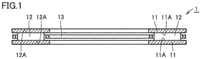
- Fig. 1 shows a structure in a cross-section along the axial direction of thrust needle roller bearing 1.
- thrust needle roller bearing 1 mainly has a pair of rolling bearing rings 11, a plurality of needle rollers 12, and a cage 13.
- Rolling bearing ring 11 is composed, for example, of steel with a carbon concentration equal to or greater than 0.4 mass %, and is formed in a disc shape. Rolling bearing ring 11 has, at its one main surface, a rolling bearing ring raceway surface 11A with which needle roller 12 is in contact. The pair of rolling bearing rings 11 is arranged such that rolling bearing ring raceway surfaces 11A face each other. Rolling bearing ring 11 has Vickers hardness equal to or greater than 700 HV. The flatness in rolling bearing ring raceway surface 11A of rolling bearing ring 11 is about 10 ⁇ m. Rolling bearing ring raceway surface 11A has a surface roughness Ra equal to or less than 0.15 ⁇ m.
- Needle roller 12 is composed of steel and has a roller rolling contact surface 12A at an outer circumferential surface. As shown in Fig. 1 , needle roller 12 is disposed between the pair of rolling bearing rings 11 such that roller rolling contact surface 12A is in contact with rolling bearing ring raceway surface 11A.
- Cage 13 is composed, for example, of a resin, and retains a plurality of needle rollers 12 at a prescribed pitch in the circumferential direction of rolling bearing ring 11. More specifically, cage 13 has a plurality of pockets formed in an annular shape and provided at equal intervals in the circumferential direction. Cage 13 accommodates needle roller 13 in the pocket.
- thrust needle roller bearing 1 is configured such that a pair of rolling bearing rings 11 can rotate relative to each other.
- Rolling bearing ring 11 is manufactured by a method of manufacturing a rolling bearing ring according to the present embodiment, which will be described below.
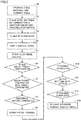
- Fig. 2 is a flowchart schematically showing the method of manufacturing a rolling bearing ring according to the present embodiment.
- Fig. 3 shows (A) change over time in current supplied to a steel material, (B) change over time in temperature of the steel material, (C) a stroke movement of a press machine, (D) an operation of a hydraulic chuck, and (E) operations of a first clamping portion and a second clamping portion, in the method of manufacturing a rolling bearing ring according to the present embodiment.
- the method of manufacturing a rolling bearing ring according to the present embodiment will be described below in the order of "S0 to S13" shown in Fig. 2 or Fig. 3 mainly with reference to the flowchart in Fig. 2 and the time chart in Fig. 3 .
- a steel material as a material for obtaining rolling bearing ring 11 is prepared (S0).
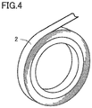
- a coil material 2 as a steel material is prepared.
- coil material 2 is formed in such a manner that a rolled steel material formed in a thin plate is wound in a coiled shape.
- the steel material wound to form coil material 2 has a main surface located on the inner circumferential side of coil material 2 in its circumferential direction and a main surface located on the outer circumferential side thereof.
- the steel material has a surface roughness Ra of 0.15 ⁇ m, for example.
- Coil material 2 is composed of steel containing 0.4 mass % or more of carbon, for example. More specifically, coil material 2 is composed, for example, of steel such as SAE1070 defined under SAE standards, S40C, S45C, S50C, S55C, and S60C defined under JIS as carbon steel for machine structural use, SUJ2 defined under JIS as high carbon chromium bearing steel, SK85 and SK95 defined under JIS as carbon tool steel, SCM440 and SCM445 defined under JIS as alloy steel for machine structural use, SKS5 defined under JIS as an alloy tool steel, SUP13 defined under JIS as a spring steel, or SUS440C defined under JIS as stainless steel.
- steel such as SAE1070 defined under SAE standards, S40C, S45C, S50C, S55C, and S60C defined under JIS as carbon steel for machine structural use
- SUJ2 defined under JIS as high carbon chromium bearing steel
- SK85 and SK95 defined under JIS as carbon tool
- Coil material 2 is a steel material in a shape of a thin plate having a thickness equal to or less than 2 mm. Coil material 2 has one main surface 21 (see Fig. 7 ) and the other main surface 22 (see Fig. 7 ) located on the opposite side of one main surface 21.
- machine part manufacturing apparatus 20 for obtaining rolling bearing ring 11 from coil material 2 is prepared (S0).
- machine part manufacturing apparatus 20 includes a forming table (work portion) 3, a heating portion 4, a tensile force applying portion 5, and a control portion 6 (which will be described later in detail).
- Work portion 3 is covered by a cover 7.
- a non-oxidizing atmosphere can be produced in the space inside cover 7.
- the non-oxidizing atmosphere is an atmosphere in which oxidation of a steel material can be suppressed, and the oxygen concentration is less than 0.01%.
- the non-oxidizing atmosphere only has to contain optional gas that is generally low in reactivity with a steel material, but this non-oxidizing atmosphere is a nitrogen atmosphere mainly containing nitrogen, for example.
- coil material 2 is placed on forming table (work portion) 3 (S2).
- Coil material 2 is placed, for example, such that main surface 21 is located on the press die 30 side in work portion 3.
- machine part manufacturing apparatus 20 will be described with reference to Fig. 7 .
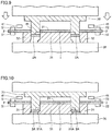
- Fig. 7 shows a cross-section along the up-down direction (the direction shown with a double-headed arrow in the figure) of work portion 3.
- Work portion 3 is formed as a press machine configured to punch a part of coil material 2 and rapidly cool the punched part of coil material 2 so as to be quenched.
- Work portion 3 mainly includes a press die 30, and forming dies 31 and 32.
- Press die 30 has a cylindrical pressing portion 35.
- Pressing portion 35 serves as a portion that is brought into contact with coil material 2 so as to punch coil material 2.
- Pressing portion 35 also has a tip end portion that is cut out to form a recess portion 35A.
- Press die 30 is disposed to face forming dies 31 and 32 in the up-down direction. By a drive mechanism (not shown), press die 30 can be caused to make a stroke movement so as to move closer to forming dies 31 and 32 or to move away from forming dies 31 and 32.
- Fig. 12 shows pressing portion 35 in a plan view. As shown by a dashed line in Fig. 12 , a water cooling circuit 35B serving as a passage for cooling water is provided inside pressing portion 35 along the circumferential direction. Fig. 12 shows an arrow showing the flow of cooling water. By circulating the cooling water so as to cool pressing portion 35 in this way, coil material 2 can rapidly be cooled (die quenched) when pressing portion 35 is brought into contact with coil material 2.
- forming dies 31 and 32 are arranged to face press die 30 in the up-down direction.
- forming die 31 has a columnar shape and also has an outer circumferential portion provided with a protruding portion 31A protruding radially outward.
- Forming die 32 is formed in a ring shape greater in diameter than forming die 31.
- Forming die 32 is arranged outside forming die 31 such that a gap is provided between forming dies 31 and 32 in the radial direction.
- pressing portion 35 is located in the gap between forming dies 31 and 32.
- Heating portion 4 serves to heat coil material 2 to the target temperature equal to or higher than an A 1 transformation point, which will be described later.
- Heating portion 4 is provided so as to be capable of heating coil material 2 by electrical heating, and mainly includes a power feed terminal 41 for feeding a direct current to coil material 2, and a DC stabilized power supply 42 connected to power feed terminal 41. Heating portion 4 can heat coil material 2 by causing a current to flow from DC stabilized power supply 42 through power feed terminal 41 into coil material 2.
- Power feed terminal 41 is located, for example, inside a first clamping portion 51 and a second clamping portion 52 which will be described later.
- power feed terminal 41 is provided such that it can be brought into contact with the portion of coil material 2 to which tensile force is applied by first clamping portion 51 and second clamping portion 52.
- the load regulation is equal to or less than 0.2% and the line regulation is equal to or less than 0.2%.
- the sampling period is equal to or less than 10 ms.
- the load regulation shows a voltage fluctuation obtained when the load current is changed while keeping the input constant, and can be measured by measuring the voltage under the unloaded condition.
- the load regulation is expressed by (E 0 - E L )/E 0 ⁇ 100% assuming that the voltage under the unloaded condition is defined as E 0 and that the rated voltage under the rated load condition is defined as E L .
- the line regulation shows an output voltage fluctuation obtained when the input voltage is changed, and can be measured by measuring the voltage of the load.
- the line regulation is expressed by (E R - E M )/E M ⁇ 100% assuming that the output voltage at the rated power supply voltage is defined as E R and that the output voltage at the upper limit or the lower limit of the rated power supply voltage is defined as E M .
- the sampling period is a reciprocal f[Hz] of a distance T[s] obtained by sampling by A-D conversion.
- Tensile force applying portion 5 serves to apply tensile force to coil material 2 in at least one direction that extends along the surface of coil material 2.
- Tensile force applying portion 5 mainly includes first clamping portion 51 and second clamping portion 52.
- First clamping portion 51 and second clamping portion 52 are provided so as to be capable of fixing coil material 2 that is punched by work portion 3, and applying tensile force to coil material 2.
- Each of first clamping portion 51 and second clamping portion 52 is configured so as to allow switching between: the state where coil material 2 is held in the up-down direction; and the state where coil material 2 is not held.
- First clamping portion 51 and second clamping portion 52 each may have any configuration and may be a hydraulic clamp or an air clamp, for example.
- First clamping portion 51 and second clamping portion 52 are positioned so as to face each other with press die 30 and forming dies 31 and 32 interposed therebetween in the extending direction of coil material 2.
- First clamping portion 51 is disposed on the side from which coil material 2 is supplied in the above-described extending direction.
- Second clamping portion 52 is disposed on the side from which coil material 2 is discharged in the above-described extending direction. In other words, at least a part of coil material 2 between the first portion held by first clamping portion 51 and the second portion held by second clamping portion 52 is disposed between press die 30 and forming dies 31, 32.
- First clamping portion 51 and second clamping portion 52 are provided so as to be movable relatively in the direction in which first clamping portion 51 and second clamping portion 52 face each other (in the extending direction of coil material 2).
- first clamping portion 51 and second clamping portion 52 each are a hydraulic clamp and include a hydraulic cylinder.
- first clamping portion 51 and second clamping portion 52 are provided so as to be movable to be away from each other by the hydraulic cylinder in the direction in which first clamping portion 51 and second clamping portion 52 face each other. Thereby, first clamping portion 51 and second clamping portion 52 can apply tensile force, in the extending direction of coil material 2, to coil material 2 disposed between press die 30 and forming dies 31, 32.
- first clamping portion 51 and second clamping portion 52 are moved to be relatively away from each other in the direction in which first clamping portion 51 and second clamping portion 52 face each other, so that tensile force is applied to a portion of coil material 2 located between the first portion held by first clamping portion 51 and the second portion held by second clamping portion 52.
- tensile force means the stress in the extending direction of coil material 2.
- First clamping portion 51 and second clamping portion 52 are provided, for example, so as to be capable of applying tensile force of 10 MPa to coil material 2.
- the tensile force applied to coil material 2 can be measured, for example, by using a load cell before the materials are set. Alternatively, the tensile force applied to coil material 2 can be measured by a load cell attached to the movable portion of the clamping device.
- Control portion 6 serves to control heating portion 4.
- Control portion 6 is provided so as to be capable of controlling the output from heating portion 4 (the value of the current supplied from DC stabilized power supply 42 through power feed terminal 41 to coil material 2).
- Control portion 6 can lower the output from heating portion 4 before the temperature of coil material 2 heated by heating portion 4 reaches the target temperature, which will be described later.
- Control portion 6 may include a temperature measuring portion (not shown) for measuring the temperature of coil material 2. In this case, control portion 6 can lower the output from heating portion 4 at the time when the temperature of coil material 2 measured by the temperature measuring portion reaches a prescribed temperature that is lower than the above-described target temperature.
- Control portion 6 lowers the output from heating portion 4, for example, when the temperature of coil material 2 reaches the temperature equal to or higher than 80 % and equal to or lower than 95% of the above-described target temperature.
- Control portion 6 may be provided so as to be capable of controlling work portion 3.
- Control portion 6 may be provided so as to be capable of controlling tensile force applying portion 5.
- Control portion 6 may be provided so as to be capable of controlling the tensile force applied to coil material 2 by tensile force applying portion 5 in accordance with the output from heating portion 4 or the temperature of coil material 2 that is measured by the above-described temperature measuring portion.
- Cover 7 includes a gas supply port 71 and a leak valve 72.
- Gas supply port 71 serves as a gas (for example, nitrogen gas) supply port through which a non-oxidizing atmosphere is produced in the space inside cover 7.
- Leak valve 72 is opened when the non-oxidizing atmosphere is changed into an air atmosphere.
- Machine part manufacturing apparatus 20 having the above-described configuration is prepared. The following steps (S3 to S13) performed in work portion 3 disposed inside cover 7 of machine part manufacturing apparatus 20 are performed under a non-oxidizing atmosphere. In other words, after coil material 2 is placed on forming table (work portion) 3, a non-oxidizing atmosphere is produced inside cover 7.
- coil material 2 is held by first clamping portion 51 and second clamping portion 52 in work portion 3 (S3).
- the pressure for holding coil material 2 is supplied to first clamping portion 51 and second clamping portion 52.
- first clamping portion 51 and second clamping portion 52 are relatively moved so as to be away from the other clamping portion in the extending direction of coil material 2.
- tensile force in accordance with the amount of relative movement of first clamping portion 51 and second clamping portion 52 (the amount of change in distance between first clamping portion 51 and second clamping portion 52) is applied to a region of coil material 2 that is located between respective portions held by first clamping portion 51 and second clamping portion 52.
- Tensile force applied to coil material 2 is greater than 0 MPa and less than 50 MPa, and preferably greater than 0 MPa and equal to or less than 30 MPa.
- the relative positional relation between first clamping portion 51 and second clamping portion 52 is maintained at least until press-forming (S9) ends. In other words, tensile force applied to coil material 2 is kept at least during a time period in which heating and press-forming are performed.
- the output from heating portion 4 is lowered (S6).
- control portion 6 lowers the value of the current supplied by DC stabilized power supply 42 to coil material 2.
- Lowered current value 12 can be set at a value at which the temperature of coil material 2 can be raised to the target temperature and kept at the target temperature, and is controlled by control portion 6.
- Such current value 12 is supplied to coil material 2, so that the temperature of coil material 2 reaches the target temperature and is kept at the target temperature for a prescribed time period (S7).
- the value of the current supplied to coil material 2 during a time period in which the temperature of coil material 2 is kept at the target temperature may be changed, and for example, is controlled to be gradually lowered as shown in Fig. 3 .
- electrical heating of coil material 2 is completed (S8).
- the heating temperature (target temperature) of coil material 2 is a temperature equal to or higher than an A 1 transformation point of steel that forms coil material 2, and for example, 1000 °C.
- the "A 1 transformation point” refers to a point corresponding to a temperature at which the structure of steel starts transformation from ferrite to austenite when steel is heated. Therefore, the structure of steel that forms coil material 2 transforms to austenite as a result of electrical heating.
- temperature T1 at the time when the output from heating portion 4 is lowered is preferably set such that the temperature of coil material 2 is equal to or higher than 80 % and equal to or lower than 95% of the above-described target temperature, and also, temperature T1 is preferably equal to or higher than 800 °C and equal to or lower than 950 °C, for example, when the target temperature is 1000 °C. Furthermore, it is preferable that the overshoot of the temperature of coil material 2 heated by heating portion 4 is suppressed to be equal to or lower than 1% of the above-described target temperature.
- the output from heating portion 4 from start to end of electrical heating may be feedback-controlled.
- machine part manufacturing apparatus 10 includes a temperature measuring portion capable of measuring the temperature of coil material 2.
- the output from heating portion 4 from start to end of electrical heating may be feedback-controlled based on the temperature of coil material 2 measured by the temperature measuring portion.
- control of the output from heating portion 4 from start to end of electrical heating is set in advance as an output pattern in accordance with coil material 2 as a workpiece.
- current value I1 supplied to coil material 2 from the start of power feed the time at which the temperature of coil material 2 reaches the temperature equal to or higher than 80% and equal to or lower than 95% of the target temperature when current value I1 is supplied, a current value I2 at which the temperature overshoot can be suppressed to be equal to or less than 1% of the target temperature, the time at which the temperature of coil material 2 reaches the target temperature when current value I2 is supplied, and the retention time period at the target temperature are calculated in advance, and set as output patterns from heating portion 4.
- the method of manufacturing a rolling bearing ring according to the present embodiment can reduce the manufacturing time period by the amount corresponding to the time period associated with feedback control (for example, several ms or more and several ten ms or less) as compared with the case where feedback control is performed, with the result that a high throughput can be achieved.
- press-forming of coil material 2 is started (S9).
- press die 30 makes a stroke movement toward forming dies 31 and 32.
- pressing portion 35 is brought into contact with coil material 2 and a part of coil material 2 is punched into a ring shape in the direction of thickness of coil material 2 (S10).
- a formed object 2A in a ring shape is thus obtained.
- formed object 2A is held for a certain period of time while it is in contact with work portion 3 (press die 30, forming die 31, and a base portion 36).
- cooling water is supplied to water cooling circuit 35B in press die 30 as described above (see Fig. 12 ).
- formed object 2A is rapidly cooled to a temperature equal to or lower than an Ms point, so that formed object 2A is quenched.
- Ms point martensite transformation point
- the method of manufacturing a rolling bearing ring includes: the step (S0) of preparing a steel material and a work portion 3 for obtaining a rolling bearing ring from the steel material; the step (S2) of placing the steel material on work portion 3; and the steps (S3 to S13) of obtaining the rolling bearing ring by heating the steel material on work portion 3 to a temperature equal to or higher than an A 1 transformation point, thereafter punching a part of the steel material into a ring shape, and thereafter quenching the steel material in a ring shape on work portion 3.
- the step of obtaining the rolling bearing ring is performed under a non-oxidizing atmosphere.
- heating and punching are performed in the state where tensile force is applied between the first portion and the second portion in the steel material that are spaced apart from each other with work portion 3 interposed therebetween in at least one direction along the main surface of the steel material.
- heating and punching are performed in the state where tensile force is applied between the first portion and the second portion in the steel material that are spaced apart from each other with work portion 3 interposed therebetween in at least one direction along the main surface of the steel material. Accordingly, as compared with the case where the above-described heating and punching are performed in the state where tensile force is not applied to the steel material in the step of obtaining the rolling bearing ring, deformation of coil material 2 caused by heating can be reduced or suppressed, so that the working quality of the rolling bearing ring to be obtained can be improved.
- rolling bearing ring 11 obtained by the method of manufacturing a rolling bearing ring according to the present embodiment is less in surface roughness than the rolling bearing ring obtained by punching coil material 2 under the air atmosphere in the state where tensile force is applied as described above.
- the detailed mechanism of this finding is uncertain but inferentially considered by the inventors of the present application as follows. Specifically, when coil material 2 is heated under the oxygen-containing atmosphere to the target temperature equal to or higher than the A 1 transformation point, an oxide film (oxide scale) is formed on the surface of this coil material 2. Then, coil material 2 is applied with tensile force and pulled thereby.
- the oxide film is broken to produce a fracture surface on this oxide film, on which an oxide film is also further formed, with the result that protrusions and recesses are formed on the oxide film.
- the protrusions and recesses on the oxide film are transferred onto the base material under the oxide film of rolling bearing ring 11, so that large protrusions and recesses are formed on the surface of rolling bearing ring 11 from which the oxide film has been removed.
- coil material 2 is heated and punched inside cover 7 placed in the non-oxidizing atmosphere.
- formation of a thick oxide film having large protrusions and recesses on the surface of coil material 2 is suppressed. Accordingly, it becomes possible to suppress an increase in surface roughness of rolling bearing ring 11 from which the oxide film has been removed, as compared with the steel material.
- the method of manufacturing a rolling bearing ring in the present embodiment since the steel material is heated under a non-oxidizing atmosphere to the temperature equal to or higher than the A 1 transformation point, formation of an oxide film by such heating is effectively suppressed.
- the method of manufacturing a rolling bearing ring according to the present embodiment does not need to include the step of removing an oxide film (oxide scale) formed on the surface of rolling bearing ring (formed object) 11. Consequently, it becomes possible to readily manufacture a rolling bearing ring in which an increase in surface roughness is suppressed as compared with a steel material.
- first clamping portion 51 and second clamping portion 52 apply tensile force to coil material 2, for example, so as to increase the distance between the first portion and the second portion in coil material 2 by the amount equal to or less than the thermal expansion amount between the first portion and the second portion therein.
- the thermal expansion amount between the first portion and the second portion in coil material 2 can be recognized as the amount obtained by multiplying the thermal expansion coefficient of coil material 2 (for example, 10 ⁇ 10 - 5/°C), a distance Lmm between the first portion and the second portion, and a temperature change ⁇ T °C after clamping of coil material 2.
- First clamping portion 51 and second clamping portion 52 are provided so as to be capable of applying tensile force, preferably, greater than 0 MPa and less than 50 MPa to coil material 2, and more preferably greater than 0 MPa and equal to or less than 30 MPa.
- the method of manufacturing a rolling bearing ring according to the present embodiment is not limited to the above-described configuration.
- the method of applying tensile force to coil material 2 is not limited to the method of using first clamping portion 51 and second clamping portion 52 provided in the vicinity of press die 30 and forming dies 31, 32 in work portion 3.
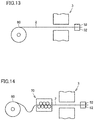
- a supply portion 60 (uncoiler) provided so as to be capable of supplying coil material 2 to work portion 3 as shown in Fig. 13 may be used, or a correction portion 70 (leveler) provided so as to be capable of correcting distortion of coil material 2 supplied from supply portion 60 to work portion 3 as shown in Fig. 14 may also be used.
- a supply portion 60 uncoiler
- a correction portion 70 leveler
- tensile force can be applied to coil material 2 located between second clamping portion 52 and both supply portion 60 and correction portion 70.
- tensile force can be applied between two points in the extending direction of coil material 2 that is held by supply portion 60 and second clamping portion 52. Furthermore, for example, by moving second clamping portion 52 so as to be away from correction portion 70 in the extending direction of coil material 2, tensile force can be applied between two points in the extending direction of coil material 2 held by correction portion 70 and second clamping portion 52.
- At least any method selected from the group consisting of electrical heating by an alternating current, indirect resistance heating, induction heating, contact heat transfer, and far-infrared heating can be adopted as the method of heating coil material 2, without being limited to electrical heating by a direct current. Each heating method will be described below in further detail.
- an object to be heated 100 (coil material 2) is heated with Joule's heat that is generated by causing a current to directly flow through object to be heated 100.
- Electrical heating by a direct current is implemented as described above.
- an alternating current is supplied from the AC power supply through power feed terminal 41 to coil material 2, to produce Joule's heat, thereby heating coil material 2.
- object to be heated 100 disposed in the vicinity of a heat generator 102 is heated indirectly with Joule's heat that is generated by causing a current to flow through heat generator 102 having a prescribed resistance.
- a direct current may be supplied to heat generator 102 or an alternating current may be supplied to heat generator 102.
- an alternating current is supplied from an AC power supply 104 to a coil 103, so that an alternating magnetic flux B is produced in object to be heated 100.
- An eddy current I is produced in object to be heated 100 in the direction cancelling alternating magnetic flux B.
- object to be heated 100 is heated by heat generation resulting from eddy current I and resistance R of object to be heated 100.
- object to be heated 100 is heated by heat transfer from an internal heating roll 105 and an external heating roll 106.
- far-infrared heating far-infrared rays are applied to an object to be heated, thereby applying far-infrared energy to the object to be heated.
- activation of vibration between atoms that form the object to be heated causes heat generation, thereby heating the object to be heated.
- the inner circumferential portion of formed object 2A is bent to be oriented in the direction of thickness of formed object 2A, so that formed object 2A is subjected to forming in work portion 3, without being limited thereto.
- the outer circumferential portion (instead of the inner circumferential portion) of formed object 2A in a ring shape may be subjected to forming.
- a protruding portion 32A protruding radially inward is formed on the inner circumferential surface of forming die 32.
- press die 30 makes a stroke movement as in the above-described embodiment
- the outer circumferential portion of formed object 2A in a ring shape is brought into contact with this protruding portion 32A. Then, press die 30 makes a stroke movement until it reaches the bottom dead center as in the above-described embodiment.
- the outer circumferential portion of formed object 2A is bent to be oriented in the direction of thickness of formed object 2A. Also in this way, formed object 2A can be subjected to forming in work portion 3 before quenching.
- the effect as that in the above-described embodiment can be achieved.
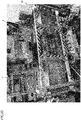
- the method of manufacturing a rolling bearing ring according to the present embodiment was executed using a coil material 2 made of steel material SAE1070 and a machine part manufacturing apparatus shown in Fig. 20 .
- the machine part manufacturing apparatus shown in Fig. 20 has the same configuration as that of machine part manufacturing apparatus 20 shown in Fig. 6 .
- a machine part manufacturing apparatus 20 including work portion 3 covered by cover 7 as shown in Fig. 5 was prepared.
- nitrogen gas (N 2 gas) was supplied to the space inside cover 7, to produce a non-oxidizing atmosphere inside cover 7 at an oxygen concentration of 0.01% or less.
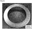
- coil material 2 was electrically heated to the temperature of 1000 °C that is equal to or higher than the A 1 transformation point, and thereafter, subjected to die-quenching. In this way, rolling bearing ring 11 in the example as shown in Fig. 21 was obtained.
- rolling bearing ring 11 high in hardness and working quality could be manufactured as a result of sufficient quenching.
- the method of manufacturing a rolling bearing ring according to the present invention may be particularly advantageously applicable to a method of manufacturing a rolling bearing ring, for which high working accuracy is required.
Landscapes
- Engineering & Computer Science (AREA)
- Chemical & Material Sciences (AREA)
- Mechanical Engineering (AREA)
- General Engineering & Computer Science (AREA)
- Thermal Sciences (AREA)
- Materials Engineering (AREA)
- Metallurgy (AREA)
- Organic Chemistry (AREA)
- Physics & Mathematics (AREA)
- Crystallography & Structural Chemistry (AREA)
- Manufacturing & Machinery (AREA)
- Heat Treatment Of Articles (AREA)
- Punching Or Piercing (AREA)
- Shaping Metal By Deep-Drawing, Or The Like (AREA)
- Rolling Contact Bearings (AREA)
Abstract
Description
- The present invention relates to a method of manufacturing a rolling bearing ring.
- A rolling bearing ring of a thrust needle bearing has conventionally been manufactured in steps below. First, a rolled steel material formed in a thin plate is wound in a coiled shape to thereby prepare a coil material. Then, the thin-plate steel material unwound from the coil material is sequentially punched and formed. Thus, a formed object in a ring shape having an approximate shape of a rolling bearing ring is obtained. Then, a setup step before heat treatment is performed. Then, the formed object in a ring shape is subjected to heat treatment such as carburization. Thereafter, the formed object is cooled with air blast, thereby quenching the formed object. Finally, the quenched formed object is press-tempered (tempered), thereby shaping the formed object. Through the steps as described above, a rolling bearing ring of a thrust needle bearing is manufactured.
- Also, die quenching has been known as a technique for forming a steel material. Die quenching is a technique for press-forming a heated steel material and simultaneously quenching the steel material by rapidly cooling the steel material in a die (for example, Japanese Patent Laying-Open No.
2008-296262 - PTD 1: Japanese Patent Laying-Open No.
2008-296262 - By die quenching as described above, however, an oxide film (oxide scale) is formed by heating on the surface of the pressed steel material. Due to the oxide film formed on the surface of the steel material, the surface roughness of the rolling bearing ring obtained by die-quenching the steel material may become higher than the surface roughness of the steel material before pressing.
- The present invention has been made to solve the above-described problems. A main object of the present invention is to provide a method of manufacturing a rolling bearing ring in which an increase in surface roughness is suppressed as compared with a steel material.
- A method of manufacturing a rolling bearing ring according to the present invention includes: preparing a steel material and a forming table for obtaining the rolling bearing ring from the steel material; placing the steel material on the forming table; and obtaining the rolling bearing ring by heating the steel material on the forming table to a temperature equal to or higher than an A1 transformation point, thereafter punching a part of the steel material into a ring shape, and thereafter quenching the steel material in a ring shape on the forming table. In the obtaining the rolling bearing ring, the heating and the punching are performed in a state where oxidation of the steel material is suppressed, and in a state where tensile force is applied between a first portion and a second portion in the steel material that are spaced apart from each other with the forming table interposed therebetween in at least one direction along a surface of the steel material.
- According to the present invention, it becomes possible to provide a method of manufacturing a rolling bearing ring in which an increase in surface roughness is suppressed as compared with a steel material.
-
-
Fig. 1 is a schematic cross-sectional view showing the configuration of a thrust needle roller bearing according to a present embodiment. -
Fig. 2 is a flowchart schematically showing a method of manufacturing a rolling bearing ring according to the present embodiment. -
Fig. 3 is a diagram showing (A) change over time in current supplied to a steel material, (B) change over time in temperature of the steel material, (C) a stroke movement of a press machine, (D) an operation of a hydraulic chuck or a pneumatic chuck, and (E) operations of a first clamping portion and a second clamping portion, in the method of manufacturing a rolling bearing ring according to the present embodiment. -
Fig. 4 is a schematic perspective view showing a coil material used in the method of manufacturing a rolling bearing ring according to the present embodiment. -
Fig. 5 is a schematic side view showing the configuration of a machine part manufacturing apparatus used in the method of manufacturing a rolling bearing ring according to the present embodiment. -
Fig. 6 is a block diagram showing the configuration of the machine part manufacturing apparatus used in the method of manufacturing a rolling bearing ring according to the present embodiment. -
Fig. 7 is a schematic cross-sectional view showing the state where a steel material is placed on a press machine in the method of manufacturing a rolling bearing ring according to the present embodiment. -
Fig. 8 is a schematic cross-sectional view showing the state where a current is supplied from a power feed terminal to the steel material in the method of manufacturing a rolling bearing ring according to the present embodiment. -
Fig. 9 is a schematic cross-sectional view showing the state where the steel material is punched by the press machine in the method of manufacturing a rolling bearing ring according to the present embodiment. -
Fig. 10 is a schematic cross-sectional view showing the state where the steel material punched into a ring shape is subjected to forming in the method of manufacturing a rolling bearing ring according to the present embodiment. -
Fig. 11 is a schematic cross-sectional view showing the state where the steel material punched into a ring shape is quenched in the method of manufacturing a rolling bearing ring according to the present embodiment. -
Fig. 12 is a schematic plan view showing a water cooling circuit provided in the press machine used in the method of manufacturing a rolling bearing ring according to the present embodiment. -
Fig. 13 is a schematic diagram for illustrating a method of applying tensile force to the steel material by using a portion for supplying the steel material. -
Fig. 14 is a schematic diagram for illustrating a method of applying tensile force to the steel material by using a portion for correcting the steel material. -
Fig. 15 is a schematic diagram for illustrating a heating method using electrical heating. -
Fig. 16 is a schematic diagram for illustrating a heating method using indirect resistance heating. -
Fig. 17 is a schematic diagram for illustrating a heating method using induction heating. -
Fig. 18 is a schematic diagram for illustrating a heating method using contact heat transfer. -
Fig. 19 is a schematic cross-sectional view for illustrating a modification of the method of manufacturing a rolling bearing ring according to the present embodiment. -
Fig. 20 shows a photograph of the machine part manufacturing apparatus used for manufacturing a rolling bearing ring according to an example. -
Fig. 21 shows a photograph of a rolling bearing ring according to the example. -
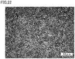
Fig. 22 shows a photograph of a steel structure in the rolling bearing ring according to the example. - Embodiments of the present invention will be hereinafter described with reference to the accompanying drawings, in which the same or corresponding components are designated by the same reference characters, and description thereof will not be repeated.
- The configuration of a thrust needle roller bearing 1 according to the present embodiment will be first described.
Fig. 1 shows a structure in a cross-section along the axial direction of thrust needle roller bearing 1. Referring toFig. 1 , thrust needle roller bearing 1 mainly has a pair of rollingbearing rings 11, a plurality ofneedle rollers 12, and acage 13. -
Rolling bearing ring 11 is composed, for example, of steel with a carbon concentration equal to or greater than 0.4 mass %, and is formed in a disc shape.Rolling bearing ring 11 has, at its one main surface, a rolling bearingring raceway surface 11A with whichneedle roller 12 is in contact. The pair of rollingbearing rings 11 is arranged such that rolling bearingring raceway surfaces 11A face each other.Rolling bearing ring 11 has Vickers hardness equal to or greater than 700 HV. The flatness in rolling bearingring raceway surface 11A of rollingbearing ring 11 is about 10 µm. Rolling bearingring raceway surface 11A has a surface roughness Ra equal to or less than 0.15 µm. -
Needle roller 12 is composed of steel and has a roller rollingcontact surface 12A at an outer circumferential surface. As shown inFig. 1 ,needle roller 12 is disposed between the pair of rollingbearing rings 11 such that roller rollingcontact surface 12A is in contact with rolling bearingring raceway surface 11A. - Cage 13 is composed, for example, of a resin, and retains a plurality of
needle rollers 12 at a prescribed pitch in the circumferential direction of rolling bearingring 11. More specifically,cage 13 has a plurality of pockets formed in an annular shape and provided at equal intervals in the circumferential direction.Cage 13 accommodatesneedle roller 13 in the pocket. - The plurality of
needle rollers 12 are rollably retained bycage 13 on an annular raceway surface along the circumferential direction of rollingbearing ring 11. With the configuration as described above, thrustneedle roller bearing 1 is configured such that a pair of rolling bearing rings 11 can rotate relative to each other.Rolling bearing ring 11 is manufactured by a method of manufacturing a rolling bearing ring according to the present embodiment, which will be described below. - Referring to
Figs. 2 to 13 , a method of manufacturing a rolling bearing ring according to the present embodiment will now be described.Fig. 2 is a flowchart schematically showing the method of manufacturing a rolling bearing ring according to the present embodiment.Fig. 3 shows (A) change over time in current supplied to a steel material, (B) change over time in temperature of the steel material, (C) a stroke movement of a press machine, (D) an operation of a hydraulic chuck, and (E) operations of a first clamping portion and a second clamping portion, in the method of manufacturing a rolling bearing ring according to the present embodiment. The method of manufacturing a rolling bearing ring according to the present embodiment will be described below in the order of "S0 to S13" shown inFig. 2 orFig. 3 mainly with reference to the flowchart inFig. 2 and the time chart inFig. 3 . - First, a steel material as a material for obtaining rolling
bearing ring 11 is prepared (S0). Specifically, referring toFig. 4 , acoil material 2 as a steel material is prepared. As shown inFig. 4 ,coil material 2 is formed in such a manner that a rolled steel material formed in a thin plate is wound in a coiled shape. The steel material wound to formcoil material 2 has a main surface located on the inner circumferential side ofcoil material 2 in its circumferential direction and a main surface located on the outer circumferential side thereof. The steel material has a surface roughness Ra of 0.15 µm, for example. -
Coil material 2 is composed of steel containing 0.4 mass % or more of carbon, for example. More specifically,coil material 2 is composed, for example, of steel such as SAE1070 defined under SAE standards, S40C, S45C, S50C, S55C, and S60C defined under JIS as carbon steel for machine structural use, SUJ2 defined under JIS as high carbon chromium bearing steel, SK85 and SK95 defined under JIS as carbon tool steel, SCM440 and SCM445 defined under JIS as alloy steel for machine structural use, SKS5 defined under JIS as an alloy tool steel, SUP13 defined under JIS as a spring steel, or SUS440C defined under JIS as stainless steel.Coil material 2 is a steel material in a shape of a thin plate having a thickness equal to or less than 2 mm.Coil material 2 has one main surface 21 (seeFig. 7 ) and the other main surface 22 (seeFig. 7 ) located on the opposite side of onemain surface 21. - Furthermore, a machine part manufacturing apparatus 20 (see
Fig. 6 ) for obtaining rollingbearing ring 11 fromcoil material 2 is prepared (S0). As shown inFigs. 5 and6 , machinepart manufacturing apparatus 20 includes a forming table (work portion) 3, aheating portion 4, a tensileforce applying portion 5, and a control portion 6 (which will be described later in detail).Work portion 3 is covered by acover 7. A non-oxidizing atmosphere can be produced in the space insidecover 7. In this case, the non-oxidizing atmosphere is an atmosphere in which oxidation of a steel material can be suppressed, and the oxygen concentration is less than 0.01%. As long as the oxygen concentration is less than 0.01%, the non-oxidizing atmosphere only has to contain optional gas that is generally low in reactivity with a steel material, but this non-oxidizing atmosphere is a nitrogen atmosphere mainly containing nitrogen, for example. - Then,
coil material 2 is placed on forming table (work portion) 3 (S2).Coil material 2 is placed, for example, such thatmain surface 21 is located on the press die 30 side inwork portion 3. Then, machinepart manufacturing apparatus 20 will be described with reference toFig. 7 . First, the configuration ofwork portion 3 will be described with reference toFig. 7. Fig. 7 shows a cross-section along the up-down direction (the direction shown with a double-headed arrow in the figure) ofwork portion 3.Work portion 3 is formed as a press machine configured to punch a part ofcoil material 2 and rapidly cool the punched part ofcoil material 2 so as to be quenched.Work portion 3 mainly includes apress die 30, and forming dies 31 and 32. - Press die 30 has a cylindrical pressing
portion 35. Pressingportion 35 serves as a portion that is brought into contact withcoil material 2 so as to punchcoil material 2. Pressingportion 35 also has a tip end portion that is cut out to form arecess portion 35A. Press die 30 is disposed to face forming dies 31 and 32 in the up-down direction. By a drive mechanism (not shown), press die 30 can be caused to make a stroke movement so as to move closer to forming dies 31 and 32 or to move away from forming dies 31 and 32. -
Fig. 12 shows pressing portion 35 in a plan view. As shown by a dashed line inFig. 12 , awater cooling circuit 35B serving as a passage for cooling water is provided inside pressingportion 35 along the circumferential direction.Fig. 12 shows an arrow showing the flow of cooling water. By circulating the cooling water so as to cool pressingportion 35 in this way,coil material 2 can rapidly be cooled (die quenched) when pressingportion 35 is brought into contact withcoil material 2. - Referring to
Fig. 7 , forming dies 31 and 32 are arranged to face press die 30 in the up-down direction. As shown inFig. 7 , formingdie 31 has a columnar shape and also has an outer circumferential portion provided with a protrudingportion 31A protruding radially outward. Forming die 32 is formed in a ring shape greater in diameter than formingdie 31. Forming die 32 is arranged outside forming die 31 such that a gap is provided between forming dies 31 and 32 in the radial direction. As shown inFig. 9 , when press die 30 makes a stroke movement toward forming dies 31 and 32, pressingportion 35 is located in the gap between forming dies 31 and 32. -
Heating portion 4 serves to heatcoil material 2 to the target temperature equal to or higher than an A1 transformation point, which will be described later.Heating portion 4 is provided so as to be capable ofheating coil material 2 by electrical heating, and mainly includes apower feed terminal 41 for feeding a direct current tocoil material 2, and a DC stabilizedpower supply 42 connected topower feed terminal 41.Heating portion 4 can heatcoil material 2 by causing a current to flow from DC stabilizedpower supply 42 throughpower feed terminal 41 intocoil material 2.Power feed terminal 41 is located, for example, inside afirst clamping portion 51 and asecond clamping portion 52 which will be described later. Also,power feed terminal 41 is provided such that it can be brought into contact with the portion ofcoil material 2 to which tensile force is applied by first clampingportion 51 and second clampingportion 52. In DC stabilizedpower supply 42, it is preferable that the load regulation is equal to or less than 0.2% and the line regulation is equal to or less than 0.2%. In DC stabilizedpower supply 42, it is preferable that the sampling period is equal to or less than 10 ms. In addition, the load regulation shows a voltage fluctuation obtained when the load current is changed while keeping the input constant, and can be measured by measuring the voltage under the unloaded condition. The load regulation is expressed by (E0 - EL)/E0 × 100% assuming that the voltage under the unloaded condition is defined as E0 and that the rated voltage under the rated load condition is defined as EL. The line regulation shows an output voltage fluctuation obtained when the input voltage is changed, and can be measured by measuring the voltage of the load. The line regulation is expressed by (ER - EM)/EM × 100% assuming that the output voltage at the rated power supply voltage is defined as ER and that the output voltage at the upper limit or the lower limit of the rated power supply voltage is defined as EM. The sampling period is a reciprocal f[Hz] of a distance T[s] obtained by sampling by A-D conversion. - Tensile
force applying portion 5 serves to apply tensile force tocoil material 2 in at least one direction that extends along the surface ofcoil material 2. Tensileforce applying portion 5 mainly includes first clampingportion 51 and second clampingportion 52. First clampingportion 51 and second clampingportion 52 are provided so as to be capable of fixingcoil material 2 that is punched bywork portion 3, and applying tensile force tocoil material 2. Each offirst clamping portion 51 and second clampingportion 52 is configured so as to allow switching between: the state wherecoil material 2 is held in the up-down direction; and the state wherecoil material 2 is not held. First clampingportion 51 and second clampingportion 52 each may have any configuration and may be a hydraulic clamp or an air clamp, for example. - First clamping
portion 51 and second clampingportion 52 are positioned so as to face each other with press die 30 and forming dies 31 and 32 interposed therebetween in the extending direction ofcoil material 2. First clampingportion 51 is disposed on the side from whichcoil material 2 is supplied in the above-described extending direction. Second clampingportion 52 is disposed on the side from whichcoil material 2 is discharged in the above-described extending direction. In other words, at least a part ofcoil material 2 between the first portion held by first clampingportion 51 and the second portion held by second clampingportion 52 is disposed between press die 30 and forming dies 31, 32. - First clamping
portion 51 and second clampingportion 52 are provided so as to be movable relatively in the direction in which first clampingportion 51 and second clampingportion 52 face each other (in the extending direction of coil material 2). For example, first clampingportion 51 and second clampingportion 52 each are a hydraulic clamp and include a hydraulic cylinder. Also, first clampingportion 51 and second clampingportion 52 are provided so as to be movable to be away from each other by the hydraulic cylinder in the direction in which first clampingportion 51 and second clampingportion 52 face each other. Thereby, first clampingportion 51 and second clampingportion 52 can apply tensile force, in the extending direction ofcoil material 2, tocoil material 2 disposed between press die 30 and forming dies 31, 32. In other words, first clampingportion 51 and second clampingportion 52 are moved to be relatively away from each other in the direction in which first clampingportion 51 and second clampingportion 52 face each other, so that tensile force is applied to a portion ofcoil material 2 located between the first portion held by first clampingportion 51 and the second portion held by second clampingportion 52. In this case, tensile force means the stress in the extending direction ofcoil material 2. - First clamping
portion 51 and second clampingportion 52 are provided, for example, so as to be capable of applying tensile force of 10 MPa tocoil material 2. The tensile force applied tocoil material 2 can be measured, for example, by using a load cell before the materials are set. Alternatively, the tensile force applied tocoil material 2 can be measured by a load cell attached to the movable portion of the clamping device. -
Control portion 6 serves to controlheating portion 4.Control portion 6 is provided so as to be capable of controlling the output from heating portion 4 (the value of the current supplied from DC stabilizedpower supply 42 throughpower feed terminal 41 to coil material 2).Control portion 6 can lower the output fromheating portion 4 before the temperature ofcoil material 2 heated byheating portion 4 reaches the target temperature, which will be described later.Control portion 6 may include a temperature measuring portion (not shown) for measuring the temperature ofcoil material 2. In this case,control portion 6 can lower the output fromheating portion 4 at the time when the temperature ofcoil material 2 measured by the temperature measuring portion reaches a prescribed temperature that is lower than the above-described target temperature.Control portion 6 lowers the output fromheating portion 4, for example, when the temperature ofcoil material 2 reaches the temperature equal to or higher than 80 % and equal to or lower than 95% of the above-described target temperature.Control portion 6 may be provided so as to be capable of controllingwork portion 3.Control portion 6 may be provided so as to be capable of controlling tensileforce applying portion 5.Control portion 6 may be provided so as to be capable of controlling the tensile force applied tocoil material 2 by tensileforce applying portion 5 in accordance with the output fromheating portion 4 or the temperature ofcoil material 2 that is measured by the above-described temperature measuring portion. -
Cover 7 includes agas supply port 71 and aleak valve 72.Gas supply port 71 serves as a gas (for example, nitrogen gas) supply port through which a non-oxidizing atmosphere is produced in the space insidecover 7.Leak valve 72 is opened when the non-oxidizing atmosphere is changed into an air atmosphere. Machinepart manufacturing apparatus 20 having the above-described configuration is prepared. The following steps (S3 to S13) performed inwork portion 3 disposed insidecover 7 of machinepart manufacturing apparatus 20 are performed under a non-oxidizing atmosphere. In other words, aftercoil material 2 is placed on forming table (work portion) 3, a non-oxidizing atmosphere is produced insidecover 7. - Then,
coil material 2 is held by first clampingportion 51 and second clampingportion 52 in work portion 3 (S3). The pressure for holdingcoil material 2 is supplied tofirst clamping portion 51 and second clampingportion 52. - Then, tensile force is applied to coil material 2 (S4). Specifically, at least one of
first clamping portion 51 and second clampingportion 52 is relatively moved so as to be away from the other clamping portion in the extending direction ofcoil material 2. Thereby, tensile force in accordance with the amount of relative movement offirst clamping portion 51 and second clamping portion 52 (the amount of change in distance between first clampingportion 51 and second clamping portion 52) is applied to a region ofcoil material 2 that is located between respective portions held by first clampingportion 51 and second clampingportion 52. Tensile force applied tocoil material 2 is greater than 0 MPa and less than 50 MPa, and preferably greater than 0 MPa and equal to or less than 30 MPa. The relative positional relation between first clampingportion 51 and second clampingportion 52 is maintained at least until press-forming (S9) ends. In other words, tensile force applied tocoil material 2 is kept at least during a time period in which heating and press-forming are performed. - Then, electrical heating is started (S5). Specifically, referring to
Fig. 8 ,power feed terminal 41 is first brought into contact withcoil material 2. Then, a current is supplied tocoil material 2 throughpower feed terminal 41. Thus,coil material 2 is heated by heat generation (Joule heat) resulting from supply of a current (electrical heating). At this time, a current value I1 (seeFig. 3 ) supplied tocoil material 2 by DC stabilizedpower supply 42 can be set at a value at whichcoil material 2 can be heated to the target temperature in a short time period. - Then, after electrical heating is started and before the temperature of
coil material 2 reaches the target temperature, the output fromheating portion 4 is lowered (S6). Preferably, when the temperature ofcoil material 2 reaches the temperature equal to or higher than 80% and equal to or lower than 95% of the target temperature,control portion 6 lowers the value of the current supplied by DC stabilizedpower supply 42 tocoil material 2. Lowered current value 12 (seeFig. 3 ) can be set at a value at which the temperature ofcoil material 2 can be raised to the target temperature and kept at the target temperature, and is controlled bycontrol portion 6. Suchcurrent value 12 is supplied tocoil material 2, so that the temperature ofcoil material 2 reaches the target temperature and is kept at the target temperature for a prescribed time period (S7). The value of the current supplied tocoil material 2 during a time period in which the temperature ofcoil material 2 is kept at the target temperature may be changed, and for example, is controlled to be gradually lowered as shown inFig. 3 . Thus, electrical heating ofcoil material 2 is completed (S8). - The heating temperature (target temperature) of
coil material 2 is a temperature equal to or higher than an A1 transformation point of steel that formscoil material 2, and for example, 1000 °C. The "A1 transformation point" refers to a point corresponding to a temperature at which the structure of steel starts transformation from ferrite to austenite when steel is heated. Therefore, the structure of steel that formscoil material 2 transforms to austenite as a result of electrical heating. Furthermore, temperature T1 at the time when the output fromheating portion 4 is lowered is preferably set such that the temperature ofcoil material 2 is equal to or higher than 80 % and equal to or lower than 95% of the above-described target temperature, and also, temperature T1 is preferably equal to or higher than 800 °C and equal to or lower than 950 °C, for example, when the target temperature is 1000 °C. Furthermore, it is preferable that the overshoot of the temperature ofcoil material 2 heated byheating portion 4 is suppressed to be equal to or lower than 1% of the above-described target temperature. - The output from
heating portion 4 from start to end of electrical heating may be feedback-controlled. For example, machinepart manufacturing apparatus 10 includes a temperature measuring portion capable of measuring the temperature ofcoil material 2. Also, the output fromheating portion 4 from start to end of electrical heating may be feedback-controlled based on the temperature ofcoil material 2 measured by the temperature measuring portion. Preferably, control of the output fromheating portion 4 from start to end of electrical heating is set in advance as an output pattern in accordance withcoil material 2 as a workpiece. For example, current value I1 supplied tocoil material 2 from the start of power feed, the time at which the temperature ofcoil material 2 reaches the temperature equal to or higher than 80% and equal to or lower than 95% of the target temperature when current value I1 is supplied, a current value I2 at which the temperature overshoot can be suppressed to be equal to or less than 1% of the target temperature, the time at which the temperature ofcoil material 2 reaches the target temperature when current value I2 is supplied, and the retention time period at the target temperature are calculated in advance, and set as output patterns fromheating portion 4. Thereby, the method of manufacturing a rolling bearing ring according to the present embodiment can reduce the manufacturing time period by the amount corresponding to the time period associated with feedback control (for example, several ms or more and several ten ms or less) as compared with the case where feedback control is performed, with the result that a high throughput can be achieved. - Then, press-forming of
coil material 2 is started (S9). Specifically, referring toFig. 9 , press die 30 makes a stroke movement toward forming dies 31 and 32. Thus, as shown inFig. 9 , pressingportion 35 is brought into contact withcoil material 2 and a part ofcoil material 2 is punched into a ring shape in the direction of thickness of coil material 2 (S10). A formedobject 2A in a ring shape is thus obtained. - Then, referring to
Fig. 10 , as press die 30 makes a further stroke movement toward forming dies 31 and 32, the inner circumferential portion of formedobject 2A is brought into contact with a protrudingportion 31A of formingdie 31. As press die 30 makes a stroke movement in this state, it reaches a bottom dead center (S11). Thus, referring toFig. 11 , the inner circumferential portion of formedobject 2A is bent to be oriented in the direction of thickness of formedobject 2A.Formed object 2A is thus subjected to forming inwork portion 3. - Then, referring to
Fig. 11 , formedobject 2A is held for a certain period of time while it is in contact with work portion 3 (press die 30, formingdie 31, and a base portion 36). Here, cooling water is supplied towater cooling circuit 35B in press die 30 as described above (seeFig. 12 ). Thus, formedobject 2A is rapidly cooled to a temperature equal to or lower than an Ms point, so that formedobject 2A is quenched. The "Ms point (martensite transformation point)" refers to a point corresponding to a temperature at which conversion to martensite is started when steel which was converted to austenite is cooled. Consequently, the structure of steel that constitutes formedobject 2A transforms into martensite. In this way, quenching (die-quenching) of formedobject 2A is completed (S12). Finally, the pressure supplied tofirst clamping portion 51 and second clampingportion 52 for holdingcoil material 2 is released (S13). Then,coil material 2 obtained as a refuse material and formedobject 2A of which quenching has been completed are taken out ofwork portion 3. At this time, tensile force applied tocoil material 2 is relaxed (S13) by relaxing the clamping force between first clampingportion 51 and second clampingportion 52. Through the steps as described above, rollingbearing ring 11 is manufactured and the method of manufacturing a rolling bearing ring according to the present embodiment is completed. - The method of manufacturing a rolling bearing ring according to the present embodiment includes: the step (S0) of preparing a steel material and a
work portion 3 for obtaining a rolling bearing ring from the steel material; the step (S2) of placing the steel material onwork portion 3; and the steps (S3 to S13) of obtaining the rolling bearing ring by heating the steel material onwork portion 3 to a temperature equal to or higher than an A1 transformation point, thereafter punching a part of the steel material into a ring shape, and thereafter quenching the steel material in a ring shape onwork portion 3. The step of obtaining the rolling bearing ring is performed under a non-oxidizing atmosphere. In the step of obtaining the rolling bearing ring, heating and punching are performed in the state where tensile force is applied between the first portion and the second portion in the steel material that are spaced apart from each other withwork portion 3 interposed therebetween in at least one direction along the main surface of the steel material. - In this way, the steps (S3 to S13) of obtaining the rolling bearing ring are carried out in the state where oxidation of the steel material is suppressed. Thus, according to the method of manufacturing a rolling bearing ring in the present embodiment, it becomes possible to obtain a rolling bearing ring in which formation of an oxide scale is suppressed.
- Furthermore, in the step of obtaining the rolling bearing ring, heating and punching are performed in the state where tensile force is applied between the first portion and the second portion in the steel material that are spaced apart from each other with
work portion 3 interposed therebetween in at least one direction along the main surface of the steel material. Accordingly, as compared with the case where the above-described heating and punching are performed in the state where tensile force is not applied to the steel material in the step of obtaining the rolling bearing ring, deformation ofcoil material 2 caused by heating can be reduced or suppressed, so that the working quality of the rolling bearing ring to be obtained can be improved. - Furthermore, the inventors of the present application have found that rolling
bearing ring 11 obtained by the method of manufacturing a rolling bearing ring according to the present embodiment is less in surface roughness than the rolling bearing ring obtained by punchingcoil material 2 under the air atmosphere in the state where tensile force is applied as described above. The detailed mechanism of this finding is uncertain but inferentially considered by the inventors of the present application as follows. Specifically, whencoil material 2 is heated under the oxygen-containing atmosphere to the target temperature equal to or higher than the A1 transformation point, an oxide film (oxide scale) is formed on the surface of thiscoil material 2. Then,coil material 2 is applied with tensile force and pulled thereby. In this case, when the amount of pullingcoil material 2 is greater than the thermal expansion amount ofcoil material 2, the oxide film is broken to produce a fracture surface on this oxide film, on which an oxide film is also further formed, with the result that protrusions and recesses are formed on the oxide film. Ascoil material 2 is punched in the state where such an oxide film is formed, the protrusions and recesses on the oxide film are transferred onto the base material under the oxide film of rollingbearing ring 11, so that large protrusions and recesses are formed on the surface of rollingbearing ring 11 from which the oxide film has been removed. - On the other hand, according to the method of manufacturing a rolling bearing ring in the present embodiment,
coil material 2 is heated and punched insidecover 7 placed in the non-oxidizing atmosphere. Thus, whencoil material 2 is punched, formation of a thick oxide film having large protrusions and recesses on the surface ofcoil material 2 is suppressed. Accordingly, it becomes possible to suppress an increase in surface roughness of rollingbearing ring 11 from which the oxide film has been removed, as compared with the steel material. - Furthermore, according to the method of manufacturing a rolling bearing ring in the present embodiment, since the steel material is heated under a non-oxidizing atmosphere to the temperature equal to or higher than the A1 transformation point, formation of an oxide film by such heating is effectively suppressed. Thus, the method of manufacturing a rolling bearing ring according to the present embodiment does not need to include the step of removing an oxide film (oxide scale) formed on the surface of rolling bearing ring (formed object) 11. Consequently, it becomes possible to readily manufacture a rolling bearing ring in which an increase in surface roughness is suppressed as compared with a steel material.
- In addition, it is preferable that, when
coil material 2 is heated to the target temperature as described later, first clampingportion 51 and second clampingportion 52 apply tensile force tocoil material 2, for example, so as to increase the distance between the first portion and the second portion incoil material 2 by the amount equal to or less than the thermal expansion amount between the first portion and the second portion therein. The thermal expansion amount between the first portion and the second portion incoil material 2 can be recognized as the amount obtained by multiplying the thermal expansion coefficient of coil material 2 (for example, 10 × 10 - 5/°C), a distance Lmm between the first portion and the second portion, and a temperature change ΔT °C after clamping ofcoil material 2. First clampingportion 51 and second clampingportion 52 are provided so as to be capable of applying tensile force, preferably, greater than 0 MPa and less than 50 MPa tocoil material 2, and more preferably greater than 0 MPa and equal to or less than 30 MPa. - The method of manufacturing a rolling bearing ring according to the present embodiment is not limited to the above-described configuration.
- The method of applying tensile force to
coil material 2 is not limited to the method of usingfirst clamping portion 51 and second clampingportion 52 provided in the vicinity of press die 30 and forming dies 31, 32 inwork portion 3. For example, in place offirst clamping portion 51 inFig. 7 , a supply portion 60 (uncoiler) provided so as to be capable of supplyingcoil material 2 to workportion 3 as shown inFig. 13 may be used, or a correction portion 70 (leveler) provided so as to be capable of correcting distortion ofcoil material 2 supplied fromsupply portion 60 to workportion 3 as shown inFig. 14 may also be used. Also in this way, by driving at least one ofsecond clamping portion 52 and bothsupply portion 60 andcorrection portion 70, tensile force can be applied tocoil material 2 located between second clampingportion 52 and bothsupply portion 60 andcorrection portion 70. - Furthermore, for example, by the rewinding operation of
supply portion 60, tensile force can be applied between two points in the extending direction ofcoil material 2 that is held bysupply portion 60 and second clampingportion 52. Furthermore, for example, by moving second clampingportion 52 so as to be away fromcorrection portion 70 in the extending direction ofcoil material 2, tensile force can be applied between two points in the extending direction ofcoil material 2 held bycorrection portion 70 and second clampingportion 52. - At least any method selected from the group consisting of electrical heating by an alternating current, indirect resistance heating, induction heating, contact heat transfer, and far-infrared heating can be adopted as the method of
heating coil material 2, without being limited to electrical heating by a direct current. Each heating method will be described below in further detail. - Referring to
Fig. 15 , in electrical heating, an object to be heated 100 (coil material 2) is heated with Joule's heat that is generated by causing a current to directly flow through object to be heated 100. Electrical heating by a direct current is implemented as described above. Meanwhile, in the case of electrical heating by an alternating current, an alternating current is supplied from the AC power supply throughpower feed terminal 41 tocoil material 2, to produce Joule's heat, therebyheating coil material 2. - Referring to
Fig. 16 , in indirect resistance heating, object to be heated 100 disposed in the vicinity of aheat generator 102 is heated indirectly with Joule's heat that is generated by causing a current to flow throughheat generator 102 having a prescribed resistance. In this case, a direct current may be supplied toheat generator 102 or an alternating current may be supplied toheat generator 102. - Referring to
Fig. 17 , in induction heating, an alternating current is supplied from anAC power supply 104 to acoil 103, so that an alternating magnetic flux B is produced in object to be heated 100. An eddy current I is produced in object to be heated 100 in the direction cancelling alternating magnetic flux B. Then, object to be heated 100 is heated by heat generation resulting from eddy current I and resistance R of object to be heated 100. - Referring to
Fig. 18 , in contact heat transfer, object to be heated 100 is heated by heat transfer from aninternal heating roll 105 and anexternal heating roll 106. In far-infrared heating, far-infrared rays are applied to an object to be heated, thereby applying far-infrared energy to the object to be heated. Thus, activation of vibration between atoms that form the object to be heated causes heat generation, thereby heating the object to be heated. - Also, in the method of manufacturing a rolling bearing ring according to the present embodiment, as shown in
Fig. 11 , the inner circumferential portion of formedobject 2A is bent to be oriented in the direction of thickness of formedobject 2A, so that formedobject 2A is subjected to forming inwork portion 3, without being limited thereto. Referring toFig. 19 , the outer circumferential portion (instead of the inner circumferential portion) of formedobject 2A in a ring shape may be subjected to forming. In this case, a protrudingportion 32A protruding radially inward is formed on the inner circumferential surface of formingdie 32. Therefore, when press die 30 makes a stroke movement as in the above-described embodiment, the outer circumferential portion of formedobject 2A in a ring shape is brought into contact with this protrudingportion 32A. Then, press die 30 makes a stroke movement until it reaches the bottom dead center as in the above-described embodiment. Thus, as shown inFig. 19 , the outer circumferential portion of formedobject 2A is bent to be oriented in the direction of thickness of formedobject 2A. Also in this way, formedobject 2A can be subjected to forming inwork portion 3 before quenching. Thus, the effect as that in the above-described embodiment can be achieved. - It could be confirmed that, in rolling
bearing ring 11 manufactured by the method of manufacturing a rolling bearing ring according to the present embodiment, an increase in surface roughness was suppressed and high working quality was achieved, as a result of evaluation as below. - In an example, the method of manufacturing a rolling bearing ring according to the present embodiment was executed using a
coil material 2 made of steel material SAE1070 and a machine part manufacturing apparatus shown inFig. 20 . The machine part manufacturing apparatus shown inFig. 20 has the same configuration as that of machinepart manufacturing apparatus 20 shown inFig. 6 . Specifically, a machinepart manufacturing apparatus 20 includingwork portion 3 covered bycover 7 as shown inFig. 5 was prepared. Then, nitrogen gas (N2 gas) was supplied to the space insidecover 7, to produce a non-oxidizing atmosphere insidecover 7 at an oxygen concentration of 0.01% or less. Then, under this non-oxidizing atmosphere, in the state where tensile force of 10 MPa was kept applied tocoil material 2 in the extending direction thereof,coil material 2 was electrically heated to the temperature of 1000 °C that is equal to or higher than the A1 transformation point, and thereafter, subjected to die-quenching. In this way, rollingbearing ring 11 in the example as shown inFig. 21 was obtained. - As a result of measuring the Vickers hardness of rolling bearing ring 11 (steel material: SAE1070) in the example manufactured in this way, the average hardness was approximately 790 HV. A part of rolling
bearing ring 11 was cut, a cross-section thereof was corroded with nital, and the microstructure in the cross-section was observed with an optical microscope. Then, a martensite structure as in a photograph inFig. 22 was observed. Also, surface roughness Ra of rollingbearing ring 11 was 0.13 µm. - Thus, it was confirmed that, according to the method of manufacturing a rolling bearing ring in the present embodiment, rolling
bearing ring 11 high in hardness and working quality could be manufactured as a result of sufficient quenching. - Although the embodiments and examples according to the present invention have been described as above, the above-descried embodiments may also be variously modified. Also, the scope of the present invention is not limited to the above-described embodiments. The scope of the present invention is defined by the terms of the claims, and is intended to include any modifications within the meaning and scope equivalent to the terms of the claims.
- The method of manufacturing a rolling bearing ring according to the present invention may be particularly advantageously applicable to a method of manufacturing a rolling bearing ring, for which high working accuracy is required.
- 1 bearing, 2 coil material, 2A formed object, 3 work portion, 4 heating portion, 5 tensile force applying portion, 6 control portion, 7 cover, 10, 20 machine part manufacturing apparatus, 11 rolling bearing ring, 11A surface, 12A rolling contact surface, 13 cage, 21, 22 main surface, 30 press die, 31, 32 forming die, 31A protruding portion, 35 pressing portion, 35A concave portion, 35B water cooling circuit, 36 base portion, 41 power feed terminal, 42 DC stabilized power supply, 51 first clamping portion, 52 second clamping portion, 60 supply portion, 70 correction portion, 71 gas supply port, 72 leak valve, 100 object to be heated, 102 heat generator, 103 coil, 104 AC power supply, 105 internal heating roll, 106 external heating roll.
Claims (7)
- A method of manufacturing a rolling bearing ring, the method comprising:preparing a steel material and a forming table for obtaining the rolling bearing ring from the steel material;placing the steel material on the forming table; andobtaining the rolling bearing ring by heating the steel material on the forming table to a temperature equal to or higher than an A1 transformation point, thereafter punching a part of the steel material into a ring shape, and thereafter quenching the steel material in a ring shape on the forming table,in the obtaining the rolling bearing ring, the heating and the punching being performed in a state where oxidation of the steel material is suppressed, and in a state where tensile force is applied between a first portion and a second portion in the steel material that are spaced apart from each other with the forming table interposed therebetween in at least one direction along a surface of the steel material.
- The method of manufacturing a rolling bearing ring according to claim 1, wherein,
in the obtaining the rolling bearing ring, the heating and the punching are performed under a non-oxidizing atmosphere in a state where tensile force is applied between the first portion and the second portion in the steel material that are spaced apart from each other with the forming table interposed therebetween in at least one direction along the surface of the steel material. - The method of manufacturing a rolling bearing ring according to claim 2, wherein, in the non-oxidizing atmosphere, an oxygen concentration is less than 0.1%.
- The method of manufacturing a rolling bearing ring according to any one of claims 1 to 3, wherein, after the obtaining the rolling bearing ring, the rolling bearing ring has a surface roughness Ra of 0.15 µm or less.
- The method of manufacturing a rolling bearing ring according to any one of claims 1 to 4, wherein the steel material contains 0.4 mass% or more of carbon and has a thickness of 2 mm or less.
- The method of manufacturing a rolling bearing ring according to any one of claims 1 to 5, wherein the rolling bearing ring having a hardness of 700 HV or more is obtained.
- The method of manufacturing a rolling bearing ring according to any one of claims 1 to 6, wherein
the steel material in a ring shape on the forming table is subjected to forming before the quenching, and
in the forming, an inner circumferential portion or an outer circumferential portion of the steel material in a ring shape is bent to be oriented in a direction of thickness of the steel material in a ring shape.
Applications Claiming Priority (2)
| Application Number | Priority Date | Filing Date | Title |
|---|---|---|---|
| JP2016048337A JP2017161046A (en) | 2016-03-11 | 2016-03-11 | Manufacturing method of bearing ring |
| PCT/JP2017/009282 WO2017154986A1 (en) | 2016-03-11 | 2017-03-08 | Bearing ring manufacturing method |
Publications (1)
| Publication Number | Publication Date |
|---|---|
| EP3428467A1 true EP3428467A1 (en) | 2019-01-16 |
Family
ID=59789591
Family Applications (1)
| Application Number | Title | Priority Date | Filing Date |
|---|---|---|---|
| EP17763326.0A Withdrawn EP3428467A1 (en) | 2016-03-11 | 2017-03-08 | Bearing ring manufacturing method |
Country Status (5)
| Country | Link |
|---|---|
| US (1) | US20200291999A1 (en) |
| EP (1) | EP3428467A1 (en) |
| JP (1) | JP2017161046A (en) |
| CN (1) | CN108779805A (en) |
| WO (1) | WO2017154986A1 (en) |
Families Citing this family (5)
| Publication number | Priority date | Publication date | Assignee | Title |
|---|---|---|---|---|
| JP6522444B2 (en) * | 2015-06-30 | 2019-05-29 | Ntn株式会社 | Bearing ring manufacturing method |
| EP3685933B1 (en) | 2019-01-25 | 2021-09-08 | Toyota Jidosha Kabushiki Kaisha | Method for processing steel plate |
| JP7052743B2 (en) * | 2019-01-25 | 2022-04-12 | トヨタ自動車株式会社 | Steel sheet forming method and punching machine |
| CN112522502B (en) * | 2020-11-11 | 2022-09-06 | 宁波江丰电子材料股份有限公司 | Treatment method for prolonging service life of ring piece |
| CN118159370A (en) * | 2021-09-01 | 2024-06-07 | 塔塔钢铁有限公司 | Press system and method for manufacturing hot stamped structural components |
Family Cites Families (10)
| Publication number | Priority date | Publication date | Assignee | Title |
|---|---|---|---|---|
| WO2005033346A1 (en) * | 2003-10-06 | 2005-04-14 | Ntn Corporation | Thin-walled part producing method, bearing raceway ring, thrust needle roller bearing, rolling bearing raceway ring producing method, rolling bearing raceway ring, and rolling bearing |
| JP4627981B2 (en) * | 2003-12-12 | 2011-02-09 | Ntn株式会社 | Manufacturing method of thin bearing race |
| JP4642490B2 (en) * | 2005-01-25 | 2011-03-02 | Ntn株式会社 | Manufacturing method of thin-walled bearing member for bearing |
| JP2006291249A (en) * | 2005-04-06 | 2006-10-26 | Ntn Corp | Equipment for producing steel-made member, thin member for bearing and thrust bearing |
| JP5121168B2 (en) * | 2006-06-01 | 2013-01-16 | Ntn株式会社 | Rolling member manufacturing method and rolling bearing manufacturing method |
| EP2163775B1 (en) * | 2007-06-27 | 2014-09-03 | NTN Corporation | Rolling member, rolling bearing and process for manufacturing rolling member |
| CN102356168A (en) * | 2009-03-19 | 2012-02-15 | Skf公司 | Method of manufacturing bearing ring |
| CN101811877A (en) * | 2009-10-30 | 2010-08-25 | 山东华夏特陶股份有限公司 | Method for rapidly sintering inner and outer rings of ceramic bearing |
| JP5927018B2 (en) * | 2011-04-26 | 2016-05-25 | Ntn株式会社 | Manufacturing method of machine parts |
| CN106488815B (en) * | 2014-07-10 | 2019-12-13 | Ntn株式会社 | Method for manufacturing bearing ring and bearing ring |
-
2016
- 2016-03-11 JP JP2016048337A patent/JP2017161046A/en active Pending
-
2017
- 2017-03-08 WO PCT/JP2017/009282 patent/WO2017154986A1/en not_active Ceased
- 2017-03-08 US US16/084,180 patent/US20200291999A1/en not_active Abandoned
- 2017-03-08 EP EP17763326.0A patent/EP3428467A1/en not_active Withdrawn
- 2017-03-08 CN CN201780016370.6A patent/CN108779805A/en active Pending
Also Published As
| Publication number | Publication date |
|---|---|
| US20200291999A1 (en) | 2020-09-17 |
| WO2017154986A1 (en) | 2017-09-14 |
| CN108779805A (en) | 2018-11-09 |
| JP2017161046A (en) | 2017-09-14 |
Similar Documents
| Publication | Publication Date | Title |
|---|---|---|
| EP3167970B1 (en) | Method of manufacturing a rolling bearing ring and rolling bearing ring | |
| US20200291999A1 (en) | Method of manufacturing rolling bearing ring | |
| CN105215160B (en) | A kind of multistation Continuous Heat stamping line and method | |
| EP3466557A1 (en) | Race production method | |
| US11786951B2 (en) | Manufacturing method for metal component and manufacturing apparatus for metal component | |
| US10730098B2 (en) | Method of manufacturing rolling bearing ring | |
| WO1996006194A1 (en) | Method and apparatus for correction tempering rolling part | |
| EP2695954B1 (en) | Annular workpiece quenching method and quenching apparatus used in the method | |
| JP6423740B2 (en) | Manufacturing method of bearing ring | |
| US12064800B2 (en) | Method for forming a sheet blank as a workpiece in a forming tool | |
| JP2017159354A (en) | Manufacturing method of raceway ring | |
| JP2017014560A (en) | Machine component production device | |
| JP2018167301A (en) | Machine component manufacturing method | |
| JP4627981B2 (en) | Manufacturing method of thin bearing race | |
| JP2016016443A (en) | Raceway manufacturing method and raceway | |
| JP6522444B2 (en) | Bearing ring manufacturing method | |
| US20250121423A1 (en) | Press system and method of manufacturing hot stamped structural component | |
| JP2007131903A (en) | Ring quenching method and apparatus for mold hardening | |
| JP2006089795A (en) | Rolling bearing race ring and its producing method, and rolling bearing |
Legal Events
| Date | Code | Title | Description |
|---|---|---|---|
| STAA | Information on the status of an ep patent application or granted ep patent |
Free format text: STATUS: THE INTERNATIONAL PUBLICATION HAS BEEN MADE |
|
| PUAI | Public reference made under article 153(3) epc to a published international application that has entered the european phase |
Free format text: ORIGINAL CODE: 0009012 |
|
| STAA | Information on the status of an ep patent application or granted ep patent |
Free format text: STATUS: REQUEST FOR EXAMINATION WAS MADE |
|
| 17P | Request for examination filed |
Effective date: 20180912 |
|
| AK | Designated contracting states |
Kind code of ref document: A1 Designated state(s): AL AT BE BG CH CY CZ DE DK EE ES FI FR GB GR HR HU IE IS IT LI LT LU LV MC MK MT NL NO PL PT RO RS SE SI SK SM TR |
|
| AX | Request for extension of the european patent |
Extension state: BA ME |
|
| DAV | Request for validation of the european patent (deleted) | ||
| DAX | Request for extension of the european patent (deleted) | ||
| STAA | Information on the status of an ep patent application or granted ep patent |
Free format text: STATUS: THE APPLICATION HAS BEEN WITHDRAWN |
|
| 18W | Application withdrawn |
Effective date: 20191227 |