EP3428446A1 - Wave power generation device - Google Patents
Wave power generation device Download PDFInfo
- Publication number
- EP3428446A1 EP3428446A1 EP17762671.0A EP17762671A EP3428446A1 EP 3428446 A1 EP3428446 A1 EP 3428446A1 EP 17762671 A EP17762671 A EP 17762671A EP 3428446 A1 EP3428446 A1 EP 3428446A1
- Authority
- EP
- European Patent Office
- Prior art keywords
- hydraulic
- hydraulic fluid
- accumulator
- discharged
- flow rate
- Prior art date
- Legal status (The legal status is an assumption and is not a legal conclusion. Google has not performed a legal analysis and makes no representation as to the accuracy of the status listed.)
- Withdrawn
Links
Images


Classifications
-
- F—MECHANICAL ENGINEERING; LIGHTING; HEATING; WEAPONS; BLASTING
- F03—MACHINES OR ENGINES FOR LIQUIDS; WIND, SPRING, OR WEIGHT MOTORS; PRODUCING MECHANICAL POWER OR A REACTIVE PROPULSIVE THRUST, NOT OTHERWISE PROVIDED FOR
- F03B—MACHINES OR ENGINES FOR LIQUIDS
- F03B13/00—Adaptations of machines or engines for special use; Combinations of machines or engines with driving or driven apparatus; Power stations or aggregates
- F03B13/12—Adaptations of machines or engines for special use; Combinations of machines or engines with driving or driven apparatus; Power stations or aggregates characterised by using wave or tide energy
- F03B13/14—Adaptations of machines or engines for special use; Combinations of machines or engines with driving or driven apparatus; Power stations or aggregates characterised by using wave or tide energy using wave energy
- F03B13/22—Adaptations of machines or engines for special use; Combinations of machines or engines with driving or driven apparatus; Power stations or aggregates characterised by using wave or tide energy using wave energy using the flow of water resulting from wave movements to drive a motor or turbine
-
- F—MECHANICAL ENGINEERING; LIGHTING; HEATING; WEAPONS; BLASTING
- F03—MACHINES OR ENGINES FOR LIQUIDS; WIND, SPRING, OR WEIGHT MOTORS; PRODUCING MECHANICAL POWER OR A REACTIVE PROPULSIVE THRUST, NOT OTHERWISE PROVIDED FOR
- F03B—MACHINES OR ENGINES FOR LIQUIDS
- F03B13/00—Adaptations of machines or engines for special use; Combinations of machines or engines with driving or driven apparatus; Power stations or aggregates
- F03B13/12—Adaptations of machines or engines for special use; Combinations of machines or engines with driving or driven apparatus; Power stations or aggregates characterised by using wave or tide energy
- F03B13/14—Adaptations of machines or engines for special use; Combinations of machines or engines with driving or driven apparatus; Power stations or aggregates characterised by using wave or tide energy using wave energy
- F03B13/16—Adaptations of machines or engines for special use; Combinations of machines or engines with driving or driven apparatus; Power stations or aggregates characterised by using wave or tide energy using wave energy using the relative movement between a wave-operated member, i.e. a "wom" and another member, i.e. a reaction member or "rem"
- F03B13/18—Adaptations of machines or engines for special use; Combinations of machines or engines with driving or driven apparatus; Power stations or aggregates characterised by using wave or tide energy using wave energy using the relative movement between a wave-operated member, i.e. a "wom" and another member, i.e. a reaction member or "rem" where the other member, i.e. rem is fixed, at least at one point, with respect to the sea bed or shore
- F03B13/1805—Adaptations of machines or engines for special use; Combinations of machines or engines with driving or driven apparatus; Power stations or aggregates characterised by using wave or tide energy using wave energy using the relative movement between a wave-operated member, i.e. a "wom" and another member, i.e. a reaction member or "rem" where the other member, i.e. rem is fixed, at least at one point, with respect to the sea bed or shore and the wom is hinged to the rem
- F03B13/1825—Adaptations of machines or engines for special use; Combinations of machines or engines with driving or driven apparatus; Power stations or aggregates characterised by using wave or tide energy using wave energy using the relative movement between a wave-operated member, i.e. a "wom" and another member, i.e. a reaction member or "rem" where the other member, i.e. rem is fixed, at least at one point, with respect to the sea bed or shore and the wom is hinged to the rem for 360° rotation
- F03B13/184—Adaptations of machines or engines for special use; Combinations of machines or engines with driving or driven apparatus; Power stations or aggregates characterised by using wave or tide energy using wave energy using the relative movement between a wave-operated member, i.e. a "wom" and another member, i.e. a reaction member or "rem" where the other member, i.e. rem is fixed, at least at one point, with respect to the sea bed or shore and the wom is hinged to the rem for 360° rotation of a water-wheel type wom
-
- F—MECHANICAL ENGINEERING; LIGHTING; HEATING; WEAPONS; BLASTING
- F03—MACHINES OR ENGINES FOR LIQUIDS; WIND, SPRING, OR WEIGHT MOTORS; PRODUCING MECHANICAL POWER OR A REACTIVE PROPULSIVE THRUST, NOT OTHERWISE PROVIDED FOR
- F03B—MACHINES OR ENGINES FOR LIQUIDS
- F03B13/00—Adaptations of machines or engines for special use; Combinations of machines or engines with driving or driven apparatus; Power stations or aggregates
- F03B13/12—Adaptations of machines or engines for special use; Combinations of machines or engines with driving or driven apparatus; Power stations or aggregates characterised by using wave or tide energy
- F03B13/14—Adaptations of machines or engines for special use; Combinations of machines or engines with driving or driven apparatus; Power stations or aggregates characterised by using wave or tide energy using wave energy
- F03B13/16—Adaptations of machines or engines for special use; Combinations of machines or engines with driving or driven apparatus; Power stations or aggregates characterised by using wave or tide energy using wave energy using the relative movement between a wave-operated member, i.e. a "wom" and another member, i.e. a reaction member or "rem"
- F03B13/18—Adaptations of machines or engines for special use; Combinations of machines or engines with driving or driven apparatus; Power stations or aggregates characterised by using wave or tide energy using wave energy using the relative movement between a wave-operated member, i.e. a "wom" and another member, i.e. a reaction member or "rem" where the other member, i.e. rem is fixed, at least at one point, with respect to the sea bed or shore
- F03B13/1805—Adaptations of machines or engines for special use; Combinations of machines or engines with driving or driven apparatus; Power stations or aggregates characterised by using wave or tide energy using wave energy using the relative movement between a wave-operated member, i.e. a "wom" and another member, i.e. a reaction member or "rem" where the other member, i.e. rem is fixed, at least at one point, with respect to the sea bed or shore and the wom is hinged to the rem
- F03B13/1825—Adaptations of machines or engines for special use; Combinations of machines or engines with driving or driven apparatus; Power stations or aggregates characterised by using wave or tide energy using wave energy using the relative movement between a wave-operated member, i.e. a "wom" and another member, i.e. a reaction member or "rem" where the other member, i.e. rem is fixed, at least at one point, with respect to the sea bed or shore and the wom is hinged to the rem for 360° rotation
- F03B13/183—Adaptations of machines or engines for special use; Combinations of machines or engines with driving or driven apparatus; Power stations or aggregates characterised by using wave or tide energy using wave energy using the relative movement between a wave-operated member, i.e. a "wom" and another member, i.e. a reaction member or "rem" where the other member, i.e. rem is fixed, at least at one point, with respect to the sea bed or shore and the wom is hinged to the rem for 360° rotation of a turbine-like wom
-
- F—MECHANICAL ENGINEERING; LIGHTING; HEATING; WEAPONS; BLASTING
- F05—INDEXING SCHEMES RELATING TO ENGINES OR PUMPS IN VARIOUS SUBCLASSES OF CLASSES F01-F04
- F05B—INDEXING SCHEME RELATING TO WIND, SPRING, WEIGHT, INERTIA OR LIKE MOTORS, TO MACHINES OR ENGINES FOR LIQUIDS COVERED BY SUBCLASSES F03B, F03D AND F03G
- F05B2260/00—Function
- F05B2260/40—Transmission of power
- F05B2260/406—Transmission of power through hydraulic systems
-
- Y—GENERAL TAGGING OF NEW TECHNOLOGICAL DEVELOPMENTS; GENERAL TAGGING OF CROSS-SECTIONAL TECHNOLOGIES SPANNING OVER SEVERAL SECTIONS OF THE IPC; TECHNICAL SUBJECTS COVERED BY FORMER USPC CROSS-REFERENCE ART COLLECTIONS [XRACs] AND DIGESTS
- Y02—TECHNOLOGIES OR APPLICATIONS FOR MITIGATION OR ADAPTATION AGAINST CLIMATE CHANGE
- Y02E—REDUCTION OF GREENHOUSE GAS [GHG] EMISSIONS, RELATED TO ENERGY GENERATION, TRANSMISSION OR DISTRIBUTION
- Y02E10/00—Energy generation through renewable energy sources
- Y02E10/30—Energy from the sea, e.g. using wave energy or salinity gradient
Definitions
- the present invention relates to a wave power generator.
- Patent Document 1 discloses a conventional wave power generator.
- the wave power generator includes a floating body swayed by waves, a large structure less swayed as compared with the floating body or not swayed by the waves, a nut and a ball screw shaft both serving as a power conversion mechanism converting relative displacement between the floating body and the large structure into rotational motion, and a generator unit which is driven by the ball screw shaft rotated by a rotative force given by the power conversion mechanism thereby to generate electric power.
- the generator unit includes a hydraulic pump which is driven by the ball screw shaft rotated about a central axis thereby to discharge a hydraulic fluid, an accumulator temporarily storing the hydraulic fluid discharged from the hydraulic pump, a hydraulic motor into which the hydraulic fluid discharged from the hydraulic pump and the hydraulic fluid temporarily stored in the accumulator flow, and a generator driven by the hydraulic motor to generate electric power.
- the floating body to which the ball screw shaft nut is coupled is moved in an up-down direction when subjected to waves. Then, the ball screw shaft is rotated about a central axis by the ball screw shaft nut moved in the up-down direction together with the floating body.
- the hydraulic pump is driven by the rotation of the ball screw shaft about the central axis thereby to discharge the hydraulic fluid. At this time, the pressure of the hydraulic fluid located between the hydraulic pump and the hydraulic motor is temporarily increased. As a result, the hydraulic fluid discharged from the hydraulic pump temporarily flows into the accumulator. In other words, the hydraulic fluid flows into the accumulator whereby the accumulator can temporarily store energy as pressure.
- the hydraulic motor is driven when the hydraulic fluid discharged from the hydraulic pump and the hydraulic fluid temporarily stored in the accumulator flow thereinto.
- the generator can successfully be driven to generate electric power in this wave power generator.
- Patent Document 1 Japanese Patent Application Publication No. JP 2013-181433
- a dimension by which the floating body is moved in the up-down direction changes with a change in the wave size.
- an amount of the hydraulic fluid discharged from the hydraulic pump per unit time (hereinafter, "flow rate") changes with the change in the dimension by which the floating body is moved in the up-down direction. That is, the flow rate of the hydraulic fluid flowing into the hydraulic motor changes in this wave power generator.
- a rotational speed of the hydraulic motor in this wave power generator.
- a generation efficiency of a generator changes with a change in a rotating speed per unit time. For example, the generation efficiency is reduced as the rotating speed per unit time is lowered. Accordingly, there is a possibility that electric power generated by the generator may fluctuate with changes in the wave size in this wave power generator.
- the present invention was made in view of the above-described circumstances in the conventional art and has an object to provide a wave power generator which can successfully generate electric power.
- a wave power generator in accordance with the invention includes a water wheel, a fluid pressure circuit and a generator.
- the water wheel is rotated when subjected to waves.
- the fluid pressure circuit includes a fluid pressure pump, a leveling circuit, a flow rate control valve and a fluid pressure motor.
- the fluid pressure pump is driven by rotation of the water wheel to discharge operating fluid.
- the leveling circuit includes an accumulator and a flow rate control valve .
- the accumulator stores the operating fluid discharged from the fluid pressure pump.
- the operating fluid discharged from the fluid pressure pump and the accumulator flows into the flow rate control valve, which discharges the operating fluid at a predetermined flow rate.
- the fluid pressure motor is driven by inflow of the operating fluid discharged from the flow rate control valve.
- the generator is driven by rotation of the fluid pressure motor to generate electric power.
- the wave power generator in accordance with the invention may further include an unloading relief valve configured to discharge the operating fluid stored in the accumulator toward the flow rate control valve when pressure of the operating fluid discharged from the fluid pressure pump becomes not more than a predetermined pressure.
- the fluid pressure motor may be driven while the operating fluid is being discharged from the accumulator, and the fluid pressure motor may be stopped when the operating fluid flows into the accumulator to be stored therein.
- a plurality of the water wheels and a plurality of the fluid pressure circuits may be provided in parallel so that the operating fluid is supplied and discharged through the respective fluid pressure circuits corresponding to the respective water wheels, and the fluid pressure circuits may include respective downstream sides which are joined together to communicate with the fluid pressure motor.
- a flow path at a downstream side of the fluid pressure pump may be divided into a plurality of leveling circuits provided in parallel, and the leveling circuits may include respective downstream sides which are joined together to communicate with the fluid pressure motor.
- a set pressure of a gas enclosed in the accumulator may be adjustable.
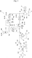
- a wave power generator of a first embodiment includes a plurality of water wheels 10, a hydraulic circuit 20 serving as a fluid pressure circuit, and an electric generator 11.
- the water wheels 10 can convert wave energy to kinetic energy.
- the water wheels 10 are installed in sea, river or a shore of lake.
- Each water wheel 10 has a rotating shaft and a rotor formed about the rotating shaft (neither of which is shown) .
- the rotating shaft extends in a vertical direction (not illustrated).
- the rotor has disc-shaped supports which spread radially about the rotating shaft from upper and lower positions of the rotating shaft and a plurality of vertically long rectangular blades which are provided between the upper and lower supports so as to radially extend in a fashion such that an angle made between the respective blades is uniform in a planar view as viewed from above (not illustrated) .
- the water wheels 10 are rotated in one direction about the respective rotating shafts with the respective rotors being subjected to waves.
- the hydraulic circuit 20 includes a reservoir 21, a plurality of hydraulic pumps 22 serving as fluid pressure pumps, a plurality of check valves 23, a relief valve 24, a leveling circuit 25, and a hydraulic motor 29 serving as a fluid pressure motor.
- the reservoir 21 reserve hydraulic fluid 21A serving as an operating fluid.
- the hydraulic pumps 22 have respective input shafts 22C to which respective upper ends of the rotating shafts of the water wheels 10 are coupled.
- the hydraulic pumps 22 are each provided with a first inflow port 22A and a first outflow port 22B.
- the first inflow ports 22A of the hydraulic pumps 22 communicate with the reservoirs 21.
- the check valves 23 are each provided with a first inflow port 23A and a second outflow port 23B.
- the respective second inflow ports 23A of the check valves 23 communicate with the respective first outflow ports 22B of the hydraulic pumps 22.
- the hydraulic fluid 21A discharged from the first outflow port 22B of the hydraulic pump 22 flows from the second inflow port 23A into the check valve 23 and flows from the second outflow port 23B out of the check valve 23.
- the hydraulic fluid 21A is not allowed to flow from the second outflow port 23B toward the second inflow port 23A.
- the check valve 23 prevents the hydraulic fluid 21A from flowing from the second outflow port 23B toward the second inflow port 23A.
- the second outflow ports 23B of the check valves 23 communicate with each other.
- the relief valve 24 is provided with a third inflow port 24A and a third outflow port 24B.
- the third inflow port 24A of the relief valve 24 communicates with the second outflow ports 23B which communicate with each other, of the check valves 23.
- the third outflow port 24B of the relief valve 24 communicates with the reservoir 21.
- the leveling circuit 25 includes an accumulator 26, an unloading relief valve 30 and a flow rate control valve 28.
- the accumulator 26 is provided with an inflow/outflow port 26A.
- the inflow/outflow port 26A communicates with the second outflow ports 23B of the check valves 23 and the third inflow port 24A of the relief valve 24.
- the hydraulic fluid 21A flows from the inflow/outflow port 26A into the accumulator 26 until the pressure of the hydraulic fluid 21A discharged from the hydraulic pumps 22 and then passing through the check valves 23 is increased to reach a predetermined pressure.
- the hydraulic fluid 21A discharged from the hydraulic pumps 22 is stored in the accumulator 26.
- the accumulator 26 has an internally provided gas enclosure region 26B in which a nitrogen gas can be enclosed.
- the accumulator 26 can adjust an amount of nitrogen gas enclosed in the gas enclosure region 26B according to the pressure of the hydraulic fluid 21A in the hydraulic circuit 20 with which the accumulator 26 communicates. In other words, a set pressure of the enclosed nitrogen gas is adjustable in the accumulator 26.
- the unloading relief valve 30 is provided with a fourth inflow port 30A and a fourth outflow port 30B.
- the fourth inflow port 30A communicates with the second outflow ports 23B of the check valves 23, the third inflow port 24A of the relief valve 24 and the inflow/outflow port 26A of the accumulator 26.
- the unloading relief valve 30 is opened to cause the hydraulic fluid 21A to flow from the fourth inflow port 30A to the fourth outlet port 30B.
- the unloading relief valve 30 is closed to stop flow of the hydraulic fluid 21A from the fourth inflow port 30A to the fourth outflow port 30B.
- the inner structure and operation of the unloading relief valve 30 will be described later.
- the flow rate control valve 28 is provided with a fifth inflow port 28A and a fifth outflow port 28B.
- the fifth inflow port 28A communicates with the fourth outflow port 30B of the unloading relief valve 30.
- the flow rate control valve 28 into which the hydraulic fluid 21A flows from the fifth inflow port adjusts the flow rate of the hydraulic fluid 21A and discharges the hydraulic fluid 21A from the fifth outflow port 28B.
- the flow rate of the hydraulic fluid 21A discharged from the fifth outflow port 28B is not changed by a change in the pressure of the hydraulic fluid 21A filling the fifth inflow port 28A.
- the flow rate control valve 28 is a pressure-compensated type.
- the hydraulic motor 29 is provided with a sixth inflow port 29A and a sixth outflow port 29B.
- the hydraulic motor 29 is further provided with an output shaft 29C.
- the sixth inflow port 29A communicates with the fifth outflow port 28B of the flow rate control valve 28.
- the sixth outflow port 29B of the hydraulic motor 29 communicates with the reservoir 21.
- the hydraulic motor 29 is driven by the hydraulic fluid 21A flowing thereinto from the sixth inflow port 29A, so that the output shaft 29C is rotated. In other words, the hydraulic motor 29 is driven by inflow of the hydraulic fluid 21A discharged from the flow rate control valve 28.
- the hydraulic fluid 21A flowing from the sixth inflow port 29A into the hydraulic motor 29 is discharged from the sixth outflow port 29B, returning to the reservoir 21.
- the hydraulic circuit 20 through which the hydraulic fluid 21A is circulated is constituted by the reservoir 21, the hydraulic motor 29, the check valves 23, the relief valve 24, the accumulator 26, the unloading relief valve 30, the flow rate control valve 28 and the hydraulic motor 29
- the output shaft 29C of the hydraulic motor 29 is coupled to the generator 11. Rotative force of the output shaft 29C of the hydraulic motor 29 which is driven and rotated by the hydraulic fluid 21A is transmitted to the generator 11, so that the generator 11 is driven to generate electric power. In other words, the generator 11 is driven by rotation of the hydraulic motor 29 to generate electric power.
- the water wheels 10 are subjected to waves thereby to be rotated about the respective rotation shafts.
- the rotative forces of the respective water wheels 10 are transmitted via the rotation shafts and the input shafts 22C to the respective hydraulic pumps 22, which are then driven.
- the hydraulic fluid 21A reserved in the reservoir 21 is caused to flow from the respective first inflow ports 22A into the hydraulic pumps 22 and then discharged from the respective first outflow ports 22B.
- the hydraulic fluid 21A discharged from the hydraulic pumps 22 and then passing through the respective check valves 23 flows into the accumulator 26.
- the hydraulic fluid 21A continuously flows into the accumulator until the pressure of the hydraulic fluid 21A discharged from the hydraulic pumps 22 and then passing through the check valves 23 is increased to reach the predetermined pressure, thereby being stored in the accumulator 26.
- the rotational speeds of the water wheels 10 are reduced, so that the flow rate of the hydraulic fluid 21A discharged from the hydraulic pumps 22 and then passing through the check valves 23 is reduced.
- the pressure of the hydraulic fluid 21A discharged from the hydraulic pumps 22 and then passing through the check valves 23 is not easily increased.
- the set pressure of the nitrogen gas enclosed in the accumulator 26 is adjusted to be reduced, so that the hydraulic fluid 21A is caused to reliably flow into the accumulator 26.
- inflow of the hydraulic fluid 21A into the accumulator 26 starts at time T 0 .
- the pressure of the hydraulic fluid 21A discharged from the hydraulic pumps 22 and then passing through the check valves 23 is increased and reaches a predetermined pressure P out at time T 1 .
- the unloading relief valve 30 is then opened. This operation is referred to as "cut-out".
- the accumulator 26 stores the hydraulic fluid 21A for a time period from time T 0 to time T 1 .
- the predetermined pressure P out has a value of 16 MPa.
- the hydraulic fluid 21A is discharged from the fourth outflow port 30B of the unloading relief valve 30, passes through the flow rate control valve 28, and flows from the sixth inflow port 29A into the hydraulic motor 29.
- the unloading relief valve 30 is configured so that the hydraulic fluid 21A stored in the accumulator 26 is discharged toward the flow rate control valve 28 when the pressure of the hydraulic fluid 21A discharged from the hydraulic pumps 22 becomes not more than the predetermined pressure P out .
- the output shaft 29C of the hydraulic motor 29 is rotated by the hydraulic fluid 21A flowing into the hydraulic motor 29. A rotational speed of the output shaft 29C per unit time at this case is designated as reference symbol "R 1 " (refer to Fig. 5(B) ).
- the hydraulic motor 29 is driven while the hydraulic fluid 21A is being discharged from the accumulator 26.
- the rotative force of the output shaft 29C of the hydraulic motor 29 is transmitted to the generator 11, which is then driven to generate electric power.
- the hydraulic fluid 21A is discharged from the sixth outflow port 29B of the hydraulic motor 29, returning to the reservoir 21.
- the hydraulic fluid 21A stored in the accumulator 26 flows through the flow rate control valve 28 into the hydraulic motor 29. Then, the pressure of the hydraulic fluid 21A discharged from the hydraulic pumps 22 and then passing through the check valves 23 is reduced and reaches a predetermined pressure P IN at time T 2 . The unloading relief valve 30 is then closed. This operation is referred to as "cut-in".
- the hydraulic fluid 21A is discharged by the accumulator 26 for the time period from the time T 1 to time T 2 .
- the predetermined pressure P IN has the value of 12.8 MPa.
- the value of P IN is 80% of the value of the predetermined pressure P OUT .
- the pressure of the hydraulic fluid 21A discharged from the hydraulic pumps 22 is repeatedly changed between P OUT and P IN , whereby the hydraulic fluid 21A intermittently flows into the hydraulic motor 29 so that the output shaft 29C is intermittently rotated so that the generator 11 is intermittently driven to generate electric power.
- the time during which rotation of the output shaft 29C of the hydraulic motor 29 is stopped becomes shorter, and the rotation time of the output shaft 29C becomes longer.
- the generator 11 to which the output shaft 29C is coupled is driven and generates electric power for a longer time.
- the output shaft 29C of the hydraulic motor 29 is continuously rotated.
- the generator 11 to which the output shaft 29C is coupled is continuously driven to generate electric power.
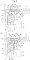
- the unloading relief valve 30 has a first cylinder 31, a plunger 32, a first compression coil spring 33, a second cylinder 34, a spool 35, a second compression coil spring 36, a piston 37, a first communication path 30C, a second communication path 30D and a third communication path 30E, in addition to the fourth inflow port 30A and the fourth outflow port 30B.
- the first cylinder 31 is cylindrical in shape and extends in the up-down direction.
- the first cylinder 31 has an upper end closed by a first closing part 31A.
- the first cylinder 31 has a lower end part formed with an inclined part 31B having an inner diameter that is reduced downward.
- One of ends of the fourth inflow port 30A communicates with a lower end of the inclined part 31B.
- One of ends of the fourth outflow port 30B communicates with an upper side surface of the inclined part 31B.
- the plunger 32 is cylindrical in shape and extends in the up-down direction.
- the plunger 32 has a lower end provided with a bottom 32A extending inward into a flat plate shape.
- the bottom 32A is formed with a through hole 32B extending therethrough in a thickness direction.
- the plunger 32 has an outer diameter that equals an inner diameter of the first cylinder 31.
- the plunger 32 has an up-down dimension that is smaller than a dimension of the first cylinder 31 from the first closing part 31A to an upper end of the inclined part 31B. The plunger 32 thus configured is inserted in the first cylinder 31 with the bottom 32A being located at a lower side.
- the first compression coil spring 33 extends in the up-down direction.
- the first compression coil spring 33 has a lower end in abutment against an upper surface of the bottom 32A and an upper end in abutment against an underside of the first closing part 31A of the first cylinder 31.
- the first compression coil spring 33 applies an elastic force to the plunger 32 in a downward direction.
- the lower end of the plunger 32 has an outer peripheral edge in abutment against an inside of the inclined part 31B of the first cylinder 31.
- the second cylinder 34 is cylindrical in shape and extends in a right-left direction.
- the second cylinder 34 has a left end closed by a second closing part 34A.
- the second cylinder 34 includes a left part having a larger inner diameter than a right part thereof.
- the second cylinder 34 is formed with a plurality of first grooves 34B extending rightward from a boundary between a left part and a right part of the inner periphery thereof.
- the second cylinder 34 is also formed with a plurality of second grooves 34C extending leftward from a right end of the right part of the inner periphery thereof.
- the spool 35 is cylindrical in shape and extends in the right-left direction.
- the spool 35 has a right end part closed by a third closing part 35A.
- the spool 35 has a right end formed with a first protrusion 35B protruding rightward.
- the spool 35 has an outer diameter that equals an inner diameter of the right part of the second cylinder 34.
- the spool 35 has a first recess 35C formed by recessing an outer diameter thereof from a right-left middle part of the outer periphery thereof to a left end.
- the spool 35 also has a second recess 35D formed by recessing an outer diameter thereof located on the right of the first recess 35C.
- the spool 35 is formed with a first communication hole 35E radially extending therethrough on the left of the third closing part 35A.
- the spool 35 is also formed with a second communication hole 35F radially extending therethrough on the left of the first recess 35C.
- the spool 35 thus formed is inserted in the right part of the second cylinder 34 with the third closing part 35A being directed rightward.
- a pressing member 38 has a left end surface formed with a second protrusion 38A protruding leftward.
- the second protrusion 38A is in abutment against the first protrusion 35B of the spool 35.
- the second compression coil spring 36 applies an elastic force to the spool 35 via the pressing member 38 leftward.
- the first recess 35C of the spool 35 has a left end overlapping and communicating with a right end of the first groove 34B of the second cylinder 34 (refer to Fig. 4(A) ).
- the first communication hole 35E of the spool 35 overlaps and communicates with the first groove 34B of the second cylinder 34 (refer to Fig. 4(A) ).
- the piston 37 has a columnar shape and extends in the right-left direction.
- the piston 37 has an outer diameter that equals an inner diameter of the left part of the second cylinder 34.
- the piston 37 has a right end formed with a third protrusion 37A protruding rightward.
- the piston 37 has a right-left dimension that is smaller than that of the left part of the second cylinder 34.
- the piston 37 thus configured is inserted in the left part of the cylinder 34 with the third protrusion 37A being directed rightward.
- a right end surface of the third protrusion 37A is in abutment against a left end surface of the spool 35.
- a left end surface of the piston 37 is spaced from the second closing part 34A of the second cylinder 34.
- the first communication path 30C has two ends one of which communicates with the fourth inflow port 30A further communicating with the lower end of the first cylinder 31.
- the other end of the first communication path 30C communicates with a part of the outer periphery of the left part of the second cylinder 34, which part is located just on the right of the second closing part 34A.
- the second communication path 30D has two ends one of which communicates with the first closing part 31A of the first cylinder 31.
- the other end of the second communication path 30D communicates with a right-left middle part of the outer periphery of the right part of the second cylinder 34. Furthermore, the other end of the second communication path 30D communicates with the first recess 35C of the spool 35.
- the third communication path 30E has two ends one of which communicates with the fourth outflow port 30B and is located near the first cylinder 31.
- the other end of the third communication path 30E communicates with the outer periphery of a right-left middle part of the right part of the second cylinder 34. Furthermore, the other end of the third communication path 30E communicates with the second recess 35D of the spool 35 (refer to Fig. 4(A) ).
- the hydraulic fluid 21A fills all of the first and second cylinders 31 and 34, the fourth inflow port 30A, the fourth outflow port 30B, and the first to third communication paths 30C-30E of the unloading relief valve 30.
- the pressure of the hydraulic fluid 21A discharged from the hydraulic pumps 22 and then passing through the check valves 23 is increased but has not reached the predetermined pressure P out (refer to Fig. 5(A) )
- the outer peripheral edge of the lower end of the plunger 32 is in abutment against the inside of the inclined part 31B of the first cylinder 31.
- the fourth inflow port 30A and the fourth outflow port 30B are separated from each other by the plunger 32 so that the unloading relief valve 30 is closed.
- the left end of the first recess 35C of the spool 35 overlaps and communicates with the right end of the first groove 34B of the second cylinder 34 (refer to Fig. 4(A) ). Furthermore, the first communication hole 35E of the spool 35 overlaps and communicates with the first groove 34B of the second cylinder 34 (refer to Fig. 4(A) ).
- the respective pressures of the hydraulic fluid 21A filling the first and second cylinders 31 and 34, the fourth inflow port 30A and the first and second communication paths 30C and 30D are the same.
- the fourth outflow port 30B and the third communication path 30E are not in communication with the first and second cylinders 31 and 34, the fourth inflow port 30A and the first and second communication paths 30C and 30D.
- the pressure of the hydraulic fluid 21A discharged from the hydraulic pumps 22 and then passing through the check valves 23 is increased to reach the predetermined pressure P out (refer to Fig. 5(A) ). Then, the respective pressures of the hydraulic fluid 21A filling the first and second cylinders 31 and 34, the fourth inflow port 30A and the first and second communication paths 30C and 30D are also increased to reach the predetermined pressure P out . As a result, the piston 37 is pushed rightward by the hydraulic fluid 21A filling the left part of the piston 37 in the second cylinder 34, so that the piston 37 and the spool 35 are moved rightward in the second cylinder 34.
- the first recess 35C of the spool 35 is also moved rightward, with the result that the left end of the first recess 35C no longer overlaps with the right end of the first groove 34B of the second cylinder 34 (refer to Fig. 4(B) ). Furthermore, the first communication hole 35E of the spool 35 overlaps and communicates with the second groove 34C of the second cylinder (refer to Fig. 4(B) ). Furthermore, the other end of the third communication path 30E communicates with the first recess 35C of the spool 35 (refer to Fig. 4(B) ).
- the third communication path 30E communicates with the second communication path 30D via the first recess 35C of the spool 35 (refer to Fig. 4(B) ).
- the pressures are reduced above the bottom 32A of the plunger 32 of the first cylinder 31, in the second communication path 30D and in the right part of the piston 37 in the second cylinder 34.
- the first cylinder 31 is partitioned into an upper part and a lower part by the bottom 32A of the plunger 32 provided with the through hole 32B.
- the upper part and the lower part of the first cylinder 31 across the bottom 32A of the plunger 32 communicate with each other via the through hole 32B. Accordingly, the pressure of the hydraulic fluid 21A filling the part below the bottom 32A of the plunger 32 is not reduced suddenly.
- the plunger 32 is pushed upward by the hydraulic fluid 21A filling the part below the bottom 32A thereby to be moved upward in the first cylinder 31.
- the fourth inflow port 30Aand the fourth outflow port 30B communicate with each other, so that the hydraulic fluid 21A flows from the fourth inflow port 30A to the fourth outflow port 30B. In other words, the unloading relief valve 30 is opened.
- the left end of the first recess 35C of the spool 35 again overlaps and communicates with the right end of the first groove 34B of the second cylinder 34 (refer to Fig. 4(A) ). Furthermore, the second communication hole 35F of the spool 35 no longer overlaps with the second groove 34C of the second cylinder 34 (refer to Fig. 4(A) ). Furthermore, the other end of the third communication path 30E again communicates with the second recess 35D of the spool 35 (refer to Fig. 4(A) ).
- the pressures of the hydraulic fluid 21A filling the part above the bottom 32A of the plunger 32 of the first cylinder 31, the second communication path 30D, and the right part of the piston 37 in the second cylinder 34 become the same as the pressures of the hydraulic fluid 21A filling the left part of the piston 37 in the second cylinder 34, the first communication path 30C and the fourth inflow port 30A.
- the plunger 32 is then moved downward in the first cylinder 31.
- the outer peripheral edge of the lower end of the plunger 32 again abuts against the inside of the inclined part 31B of the first cylinder 31, with the result that the fourth inflow port 30A and the fourth outflow port 30B are again separated from each other (refer to Fig. 4(A) ).
- the unloading relief valve 30 is closed again.
- the hydraulic fluid 21A discharged from the hydraulic pumps 22 and then passing through the check valves 23 again flows into the accumulator 26.
- the flow rate control valve 28 is provided between the accumulator 26 and the hydraulic motor 29 in this wave power generator. Accordingly, the flow rate of the hydraulic fluid flowing into the hydraulic motor 29 can be adjusted to the predetermined flow rate. As a result, the flow rate of the hydraulic fluid flowing into the hydraulic motor 29 can be suppressed to the predetermined flow rate even when the rotational speeds of the water wheels 10 are changed by the wave size and thereby the flow rate of the hydraulic fluid 21A discharged from the hydraulic pumps 22 is changed. Furthermore, when the flow rate of the hydraulic fluid 21A discharged from the hydraulic pumps 22 is over the flow rate at which the hydraulic fluid 21A can pass through the flow rate control valve 28, the hydraulic fluid 21A that cannot pass through the flow rate control valve 28 can be temporarily stored in the accumulator 26.
- the wave power generator in accordance with the invention can successfully generate electric power.
- the wave power generator is provided with the unloading relief valve 30 which discharges the hydraulic fluid 21A stored in the accumulator 26 toward the flow rate control valve 28 when the pressure of the hydraulic fluid 21A discharged from the hydraulic pumps 22 becomes not more than the predetermined pressure.
- the unloading relief valve 30 is opened.
- the hydraulic motor 29 is driven while the hydraulic fluid 21A is being discharged from the accumulator 26, and the hydraulic motor 29 is stopped when the hydraulic fluid 21A flows into the accumulator 26 to be stored therein. Accordingly, :the hydraulic motor 29 and the generator 11 can reliably be driven with respective efficient rotational speeds per unit time. As a result, the generating efficiency can be further improved even when the water wheels 10 are rotated while being subjected to small waves, with the result that an amount of generated power can be further increased.
- a set pressure of gas enclosed in the accumulator 26 is adjustable. Accordingly, the pressure to discharge the hydraulic fluid 21A stored in the accumulator 26 can be adjusted. In other words, the set pressure of nitrogen gas enclosed in the accumulator 26 is adjusted according to the wave size in the location where the wave power generator is installed. As a result, the hydraulic fluid 21A can successfully be caused to flow into and out of the accumulator 26 even when the hydraulic pumps 22 are driven by different waves in the installation location of the wave power generator and thereby discharge the hydraulic fluid 21A with different flow rates.
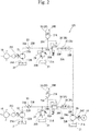
- the wave power generator of a second embodiment differs from that of the first embodiment in that the downstream sides of the hydraulic circuit 120 are joined together to communicate with the hydraulic motor 29 as illustrated in Fig. 2 .
- the other construction is the same as that of the first embodiment. Identical or similar parts are labeled by the same reference symbols as those in the first embodiment, and the detailed description of these parts will be eliminated.
- the water wheels 10 include respective rotating shafts having respective upper ends coupled to the respective input shafts 22C of the hydraulic pumps 22.
- the check valves 23 include the respective second inflow ports 23A communicating with the respective first outflow ports 22B of the hydraulic pumps 22.
- a plurality of the relief valves 24 includes the respective third inflow ports 24A communicating with the respective second discharge ports 23B of the check valves 23. Furthermore, a plurality of the accumulators 26 has the respective inflow/outflow ports 26A communicating with the respective second discharge ports 23B of the check valves 23 and the respective third inflow ports 24A of the relief valves 24.
- a plurality of the unloading relief valves 30 includes the respective fourth inflow ports 30A communicating with the respective second discharge ports 23B of the check valves 23, the respective third inflow ports 24A of the relief valves 24 and the respective inflow/outflow ports 26A of the accumulators 26.
- a plurality of the flow rate control valves 28 includes the respective fifth inflow ports 28A communicating with the respective fourth discharge ports 30B of the unloading relief valves 30. Furthermore, the fifth discharge ports 28B of the flow rate control valves 28 communicate with each other. The fifth discharge ports 28B communicating with each other further communicate with the sixth inflow port 29A of the hydraulic motor 29.
- the water wheels 10 and the hydraulic circuits 120 through which the operating fluid is supplied and discharged corresponding to the respective water wheels 10 are provided in parallel, and the downstream sides of the hydraulic circuits 120 are joined together to communicate with the hydraulic motor 29.
- the water wheels 10 are rotated about respective rotational shafts with the respective rotors being subjected to waves. Rotative forces of the water wheels 10 are transmitted to the respective hydraulic pumps 22 of the respective hydraulic circuits 120, so that the hydraulic pumps 22 are driven.
- the hydraulic fluid 21A reserved in the reservoir 21 flows from the respective first inflow ports 22A into the hydraulic pumps 22.
- the hydraulic fluid 21A discharged from the respective hydraulic pumps 22 and then passing through the respective check valves 23 flows into the respective accumulators 26.
- the respective unloading relief valves 30 When the pressures of the hydraulic fluid 21A discharged from the respective hydraulic pumps 22 and then passing through the respective check valves 23 are increased to reach the predetermined pressure, the respective unloading relief valves 30 are opened.
- the hydraulic fluid 21A discharged from the respective fourth discharge ports 30B of the unloading relief valves 30 passes through the respective flow rate control valves 28 to be joined together, and flows from the sixth inflow port 29A into the hydraulic motor 29.
- the output shaft 29C of the hydraulic motor 29 is rotated by the hydraulic fluid 21A flowing into the hydraulic motor 29.
- the rotative force of the output shaft 29C of the hydraulic motor 29 is transmitted to the generator 11, which is then driven to generate electric power.
- the flow rate control valves 28 are provided between the accumulators 26 and the hydraulic motor 29 also in the wave power generator of the second embodiment. Accordingly, the flow rate of the hydraulic fluid 21A flowing into the hydraulic motor 29 can be adjusted to the predetermined flow rate. As a result, the flow rate of the hydraulic fluid 21A flowing into the hydraulic motor 29 can be suppressed to the predetermined flow rate even when the rotational speeds of the water wheels 10 are changed by the wave size and thereby the flow rates of the hydraulic fluid 21A discharged from the hydraulic pumps 22 are changed.
- the hydraulic fluid 21A that cannot pass through the flow rate control valve 28 can be temporarily stored in the accumulator 26. Furthermore, when the flow rate of the hydraulic fluid 21A discharged from the hydraulic pump 22 is less than the flow rate at which the hydraulic fluid 21A can pass through the flow rate control valve 28, the hydraulic fluid 21A stored in the accumulator 26 can pass through the flow rate control valve 28 and flow into the hydraulic motor 29. As a result, the rotation of the hydraulic motor 29 can be leveled, so that the generator 11 can stably be driven to generate electric power.
- the wave power generator in accordance with the invention can successfully generate electric power.
- the wave power generator is provided with the unloading relief valves 30 each of which discharges the hydraulic fluid 21A stored in the accumulator 26 toward the flow rate control valve 28 when the pressure of the hydraulic fluid 21A discharged from the hydraulic pump 22 becomes not more than the predetermined pressure.
- the hydraulic fluid 21A discharged from the respective hydraulic pumps 22 is stored in the respective accumulators 26.
- the unloading relief valve 30 is opened.
- the hydraulic motor 29 is driven while the hydraulic fluid 21A is being discharged from the accumulators 26, and the hydraulic motor 29 is stopped when the hydraulic fluid 21A flows into the accumulators 26 to be stored therein. Accordingly, the hydraulic motor 29 and the generator 11 can reliably be driven with respective efficient rotational speeds per unit time. As a result, the generating efficiency can be further improved even when the water wheels 10 are rotated while being subjected to small waves, with the result that an amount of generated power can be further increased.
- the water wheels 10 and the hydraulic circuits 120 are provided in parallel so that the hydraulic fluid 21A is supplied and discharged through the respective hydraulic circuits corresponding to the respective water wheels 10, and the downstream sides of the hydraulic circuits 120 are joined together to communicate with the hydraulic motor 29.
- the water wheels 10 can receive a wider range of wave to be rotated.
- the water wheels 10 can receive various sizes of waves as compared with a case where a single water wheel is provided, with the result that the drive of the generator 11 can be leveled.
- this wave power generator can suppress fluctuation in the electric power generated by the generator 11.
- a set pressure of gas enclosed in the respective accumulators 26 is adjustable. Accordingly, the pressure to discharge the hydraulic fluid 21A stored in the respective accumulators 26 can be adjusted. In other words, the set pressure of nitrogen gas enclosed in the respective accumulators 26 is adjusted according to the wave size in the location where the wave power generator is installed. As a result, the hydraulic fluid 21A can successfully be caused to flow into and out of the respective accumulators 26 even when the hydraulic pumps 22 are driven by different waves in the installation location of the wave power generator and thereby discharge the hydraulic fluid 21A with different flow rates.
- the wave power generator of a third embodiment differs from those of the first and second embodiments in that leveling circuits 25 are provided in parallel each of which includes the accumulator 26, the unloading relief valve 30 and the flow rate control valve 28, and that the inflow/outflow ports 26A of the accumulators 26 communicate with each other.
- the other construction is the same as that of the first and second embodiments. Identical or similar parts are labeled by the same reference symbols as those in the first and second embodiments, and the detailed description of these parts will be eliminated.
- the respective fifth inflow ports 28A of the flow rate control valves 28 communicate with the respective inflow/outflow ports 26A of the accumulators 26. Furthermore, the respective fifth inflow ports 28A of the flow rate control valves 28 communicate with the respective fourth discharge ports 30B of the unloading relief valves 30.
- the respective leveling circuits 25 are thus configured. Furthermore, the respective inflow/outflow ports 26A of the accumulators 26 communicate with each other. The inflow/outflow ports 26A of the accumulators 26 communicate with the second discharge port 23B of the check valve 23 and the third inflow port 24A of the relief valve 24.
- the fifth discharge ports 28B of the flow rate control valves 28 communicate with each other.
- the fifth discharge ports 28B communicating with each other further communicate with the sixth inflow port 29A of the hydraulic motor 29.
- a flow path at the downstream side of the hydraulic pump 22 is divided into a plurality of leveling circuits 25 provided in parallel, and downstream sides of the leveling circuits 25 are joined together to communicate with the hydraulic motor 29.
- the water wheel 10 is rotated about the rotational shaft with the rotor being subjected to waves. Rotative force of the water wheel 10 is transmitted to the hydraulic pump 22, so that the hydraulic pump 22 is driven.
- the hydraulic fluid 21A reserved in the reservoir 21 flows from the first inflow port 22A into the hydraulic pump 22.
- the hydraulic fluid 21A discharged from the hydraulic pump 22 and then passing through the check valve 23 flows into the respective accumulators 26 of the respective leveling circuits 25.
- the unloading relief valves 30 When the pressure of the hydraulic fluid 21A discharged from the hydraulic pump 22 and then passing through the check valve 23 is increased to reach the predetermined pressure, the unloading relief valves 30 are opened.
- the hydraulic fluid 21A discharged from the fourth discharge ports 30B of the unloading relief valves 30 passes through the flow rate control valves 28 and flows from the sixth inflow port 29A into the hydraulic motor 29.
- the output shaft 29C of the hydraulic motor 29 is rotated by the hydraulic fluid 21A flowing into the hydraulic motor 29.
- the rotative force of the output shaft 29C of the hydraulic motor 29 is transmitted to the generator 11, which is then driven to generate electric power.
- the flow rate control valves 28 are provided between the accumulators 26 and the hydraulic motor 29 also in the wave power generator of the third embodiment. Accordingly, the flow rate of the hydraulic fluid 21A flowing into the hydraulic motor 29 can be adjusted to the predetermined flow rate. As a result, the flow rate of the hydraulic fluid 21A flowing into the hydraulic motor 29 can be suppressed to the predetermined flow rate even when the rotational speed of the water wheel 10 is changed by the wave size and thereby the flow rate of the hydraulic fluid 21A discharged from the hydraulic pump 22 is changed.
- the hydraulic fluid 21A that cannot pass through the respective flow rate control valves 28 can be temporarily stored in the respective accumulators 26. Furthermore, when the flow rate of the hydraulic fluid 21A discharged from the hydraulic pump 22 is less than the flow rate at which the hydraulic fluid 21A can pass through the respective flow rate control valves 28, the hydraulic fluid 21A stored in the respective accumulators 26 can pass through the respective flow rate control valves 28 and flow into the hydraulic motor 29. As a result, the rotation of the hydraulic motor 29 can be leveled, so that the generator 11 can stably be driven to generate electric power.
- the wave power generator in accordance with the invention can successfully generate electric power.
- the wave power generator is provided with the unloading relief valves 30 each of which discharges the hydraulic fluid 21A stored in the accumulator 26 toward the flow rate control valve 28 when the pressure of the hydraulic fluid 21A discharged from the hydraulic pump 22 becomes not more than the predetermined pressure.
- the hydraulic fluid 21A discharged from the hydraulic pump 22 is stored in the respective accumulators 26.
- the unloading relief valves 30 are opened.
- the hydraulic motor 29 is driven while the hydraulic fluid 21A is being discharged from the accumulators 26, and the hydraulic motor 29 is stopped when the hydraulic fluid 21A flows into the accumulators 26 to be stored therein. Accordingly, the hydraulic motor 29 and the generator 11 can reliably be driven with respective efficient rotational speeds per unit time. As a result, the generating efficiency can be further improved even when the water wheel 10 is rotated while being subjected to small waves, with the result that an amount of generated power can be further increased.
- the flow path at the downstream side of the hydraulic pump 22 is divided into a plurality of the leveling circuits 25 provided in parallel, and the downstream sides of the leveling circuits 25 are joined together thereby to communicate with the hydraulic motor 29.
- the hydraulic fluid 21A discharged from the hydraulic pump 22 flows into the respective leveling circuits 25, the accumulators 26 and the flow rate control valves 28 both of which are provided in the respective leveling circuits 25 can be rendered smaller in size.
- an amount of hydraulic fluid 21A that is discharged from the hydraulic pump 22 and allowed to flow into the respective accumulators 26 can easily be changed by changing the number of the leveling circuits 25.
- a set pressure of the gas enclosed in the respective accumulators 26 is adjustable. Accordingly, the pressure to discharge the hydraulic fluid 21A stored in the respective accumulators 26 can be adjusted. In other words, the set pressure of nitrogen gas enclosed in the respective accumulators 26 is adjusted according to the wave size in the installation location of the wave power generator. As a result, the hydraulic fluid 21A can successfully be caused to flow into and out of the respective accumulators 26 even when the hydraulic pump 22 is driven by different waves in the installation location of the wave power generator and thereby discharges the hydraulic fluid 21A with different flow rates.
Landscapes
- Engineering & Computer Science (AREA)
- Chemical & Material Sciences (AREA)
- Combustion & Propulsion (AREA)
- Mechanical Engineering (AREA)
- General Engineering & Computer Science (AREA)
- Other Liquid Machine Or Engine Such As Wave Power Use (AREA)
- Fluid-Pressure Circuits (AREA)
Abstract
Description
- The present invention relates to a wave power generator.
- Patent Document 1 discloses a conventional wave power generator. The wave power generator includes a floating body swayed by waves, a large structure less swayed as compared with the floating body or not swayed by the waves, a nut and a ball screw shaft both serving as a power conversion mechanism converting relative displacement between the floating body and the large structure into rotational motion, and a generator unit which is driven by the ball screw shaft rotated by a rotative force given by the power conversion mechanism thereby to generate electric power.
- The generator unit includes a hydraulic pump which is driven by the ball screw shaft rotated about a central axis thereby to discharge a hydraulic fluid, an accumulator temporarily storing the hydraulic fluid discharged from the hydraulic pump, a hydraulic motor into which the hydraulic fluid discharged from the hydraulic pump and the hydraulic fluid temporarily stored in the accumulator flow, and a generator driven by the hydraulic motor to generate electric power.
- In this wave power generator, the floating body to which the ball screw shaft nut is coupled is moved in an up-down direction when subjected to waves. Then, the ball screw shaft is rotated about a central axis by the ball screw shaft nut moved in the up-down direction together with the floating body. The hydraulic pump is driven by the rotation of the ball screw shaft about the central axis thereby to discharge the hydraulic fluid. At this time, the pressure of the hydraulic fluid located between the hydraulic pump and the hydraulic motor is temporarily increased. As a result, the hydraulic fluid discharged from the hydraulic pump temporarily flows into the accumulator. In other words, the hydraulic fluid flows into the accumulator whereby the accumulator can temporarily store energy as pressure. The hydraulic motor is driven when the hydraulic fluid discharged from the hydraulic pump and the hydraulic fluid temporarily stored in the accumulator flow thereinto. Thus, since the hydraulic fluid can reliably be supplied from the hydraulic pump to the hydraulic motor, the generator can successfully be driven to generate electric power in this wave power generator.
- Patent Document 1: Japanese Patent Application Publication No.
JP 2013-181433 - In the wave power generator of Patent Document 1, however, a dimension by which the floating body is moved in the up-down direction changes with a change in the wave size. In other words, an amount of the hydraulic fluid discharged from the hydraulic pump per unit time (hereinafter, "flow rate") changes with the change in the dimension by which the floating body is moved in the up-down direction. That is, the flow rate of the hydraulic fluid flowing into the hydraulic motor changes in this wave power generator. For this reason, there is a possibility that fluctuation may occur in a rotational speed of the hydraulic motor in this wave power generator. In general, a generation efficiency of a generator changes with a change in a rotating speed per unit time. For example, the generation efficiency is reduced as the rotating speed per unit time is lowered. Accordingly, there is a possibility that electric power generated by the generator may fluctuate with changes in the wave size in this wave power generator.
- The present invention was made in view of the above-described circumstances in the conventional art and has an object to provide a wave power generator which can successfully generate electric power.
- A wave power generator in accordance with the invention includes a water wheel, a fluid pressure circuit and a generator. The water wheel is rotated when subjected to waves. The fluid pressure circuit includes a fluid pressure pump, a leveling circuit, a flow rate control valve and a fluid pressure motor. The fluid pressure pump is driven by rotation of the water wheel to discharge operating fluid. The leveling circuit includes an accumulator and a flow rate control valve . The accumulator stores the operating fluid discharged from the fluid pressure pump. The operating fluid discharged from the fluid pressure pump and the accumulator flows into the flow rate control valve, which discharges the operating fluid at a predetermined flow rate. The fluid pressure motor is driven by inflow of the operating fluid discharged from the flow rate control valve. The generator is driven by rotation of the fluid pressure motor to generate electric power.
- The wave power generator in accordance with the invention may further include an unloading relief valve configured to discharge the operating fluid stored in the accumulator toward the flow rate control valve when pressure of the operating fluid discharged from the fluid pressure pump becomes not more than a predetermined pressure.
- In the wave power generator in accordance with the invention, the fluid pressure motor may be driven while the operating fluid is being discharged from the accumulator, and the fluid pressure motor may be stopped when the operating fluid flows into the accumulator to be stored therein.
- In the wave power generator in accordance with the invention, a plurality of the water wheels and a plurality of the fluid pressure circuits may be provided in parallel so that the operating fluid is supplied and discharged through the respective fluid pressure circuits corresponding to the respective water wheels, and the fluid pressure circuits may include respective downstream sides which are joined together to communicate with the fluid pressure motor.
- In the wave power generator in accordance with the invention, a flow path at a downstream side of the fluid pressure pump may be divided into a plurality of leveling circuits provided in parallel, and the leveling circuits may include respective downstream sides which are joined together to communicate with the fluid pressure motor.
- In the wave power generator in accordance with the invention, a set pressure of a gas enclosed in the accumulator may be adjustable.
-
-
Fig. 1 is a schematic view of the wave power generator of a first embodiment; -
Fig. 2 is a schematic view of the wave power generator of a second embodiment; -
Fig. 3 is a schematic view of the wave power generator of a third embodiment; -
Figs. 4 (A) and 4 (B) are schematic diagrams of an unloading relief valve (A) in a closed state and (B) in an open state, respectively; and -
Figs. 5(A) and 5(B) are graphs showing (A) changes in pressure of operating fluid discharged from a fluid pressure pump and then passed through a check valve and (B) changes in rotational speed of the fluid pressure motor per unit time, respectively. - Referring to
Fig. 1 , a wave power generator of a first embodiment includes a plurality ofwater wheels 10, ahydraulic circuit 20 serving as a fluid pressure circuit, and anelectric generator 11. Thewater wheels 10 can convert wave energy to kinetic energy. Thewater wheels 10 are installed in sea, river or a shore of lake. Eachwater wheel 10 has a rotating shaft and a rotor formed about the rotating shaft (neither of which is shown) . The rotating shaft extends in a vertical direction (not illustrated). The rotor has disc-shaped supports which spread radially about the rotating shaft from upper and lower positions of the rotating shaft and a plurality of vertically long rectangular blades which are provided between the upper and lower supports so as to radially extend in a fashion such that an angle made between the respective blades is uniform in a planar view as viewed from above (not illustrated) . Thewater wheels 10 are rotated in one direction about the respective rotating shafts with the respective rotors being subjected to waves. - The
hydraulic circuit 20 includes areservoir 21, a plurality ofhydraulic pumps 22 serving as fluid pressure pumps, a plurality ofcheck valves 23, arelief valve 24, aleveling circuit 25, and ahydraulic motor 29 serving as a fluid pressure motor. Thereservoir 21 reservehydraulic fluid 21A serving as an operating fluid. - The
hydraulic pumps 22 haverespective input shafts 22C to which respective upper ends of the rotating shafts of thewater wheels 10 are coupled. Thehydraulic pumps 22 are each provided with afirst inflow port 22A and afirst outflow port 22B. Thefirst inflow ports 22A of thehydraulic pumps 22 communicate with thereservoirs 21. When thewater wheel 10 is rotated about the rotating shaft with the rotor being subjected to waves, the rotative force is transmitted through the rotating shaft and theinput shaft 22C to thehydraulic pump 22 which is thereby driven, with the result that the hydraulic fluid flows from thefirst inflow port 22A into thehydraulic pump 10. Thehydraulic fluid 21A flowing from thefirst inflow port 22A into thehydraulic pump 22 is discharged from thefirst outflow port 22B. In other words, thehydraulic pumps 22 are driven by rotation of thewater wheels 10 to discharge thehydraulic fluid 21A. - The
check valves 23 are each provided with afirst inflow port 23A and asecond outflow port 23B. The respectivesecond inflow ports 23A of thecheck valves 23 communicate with the respectivefirst outflow ports 22B of thehydraulic pumps 22. Thehydraulic fluid 21A discharged from thefirst outflow port 22B of thehydraulic pump 22 flows from thesecond inflow port 23A into thecheck valve 23 and flows from thesecond outflow port 23B out of thecheck valve 23. In thecheck valve 23, thehydraulic fluid 21A is not allowed to flow from thesecond outflow port 23B toward thesecond inflow port 23A. In other words, thecheck valve 23 prevents thehydraulic fluid 21A from flowing from thesecond outflow port 23B toward thesecond inflow port 23A. Thesecond outflow ports 23B of thecheck valves 23 communicate with each other. - The
relief valve 24 is provided with athird inflow port 24A and athird outflow port 24B. Thethird inflow port 24A of therelief valve 24 communicates with thesecond outflow ports 23B which communicate with each other, of thecheck valves 23. Thethird outflow port 24B of therelief valve 24 communicates with thereservoir 21. When pressure of thehydraulic fluid 21A at thethird inflow port 24A side exceeds a predetermined pressure, therelief valve 24 causes thehydraulic fluid 21A to flow from thethird inflow port 24A to thethird outflow port 24B. - The leveling
circuit 25 includes anaccumulator 26, an unloadingrelief valve 30 and a flowrate control valve 28. Theaccumulator 26 is provided with an inflow/outflow port 26A. The inflow/outflow port 26A communicates with thesecond outflow ports 23B of thecheck valves 23 and thethird inflow port 24A of therelief valve 24. Thehydraulic fluid 21A flows from the inflow/outflow port 26A into theaccumulator 26 until the pressure of thehydraulic fluid 21A discharged from thehydraulic pumps 22 and then passing through thecheck valves 23 is increased to reach a predetermined pressure. In other words, thehydraulic fluid 21A discharged from thehydraulic pumps 22 is stored in theaccumulator 26. Furthermore, theaccumulator 26 has an internally providedgas enclosure region 26B in which a nitrogen gas can be enclosed. Theaccumulator 26 can adjust an amount of nitrogen gas enclosed in thegas enclosure region 26B according to the pressure of thehydraulic fluid 21A in thehydraulic circuit 20 with which theaccumulator 26 communicates. In other words, a set pressure of the enclosed nitrogen gas is adjustable in theaccumulator 26. - The unloading
relief valve 30 is provided with afourth inflow port 30A and afourth outflow port 30B. Thefourth inflow port 30A communicates with thesecond outflow ports 23B of thecheck valves 23, thethird inflow port 24A of therelief valve 24 and the inflow/outflow port 26A of theaccumulator 26. When the pressure of the hydraulic fluid discharged from thehydraulic pumps 22 and then passing through thecheck valves 23 becomes not less than the predetermined pressure, the unloadingrelief valve 30 is opened to cause thehydraulic fluid 21A to flow from thefourth inflow port 30A to thefourth outlet port 30B. Furthermore, when the pressure of the hydraulic fluid discharged from thehydraulic pumps 22 and then passing through thecheck valves 23 becomes not more than a predetermined pressure, the unloadingrelief valve 30 is closed to stop flow of thehydraulic fluid 21A from thefourth inflow port 30A to thefourth outflow port 30B. The inner structure and operation of the unloadingrelief valve 30 will be described later. - The flow
rate control valve 28 is provided with afifth inflow port 28A and afifth outflow port 28B. Thefifth inflow port 28A communicates with thefourth outflow port 30B of the unloadingrelief valve 30. The flowrate control valve 28 into which thehydraulic fluid 21A flows from the fifth inflow port adjusts the flow rate of thehydraulic fluid 21A and discharges thehydraulic fluid 21A from thefifth outflow port 28B. In the flowrate control valve 28, the flow rate of thehydraulic fluid 21A discharged from thefifth outflow port 28B is not changed by a change in the pressure of thehydraulic fluid 21A filling thefifth inflow port 28A. In other words, the flowrate control valve 28 is a pressure-compensated type. - The
hydraulic motor 29 is provided with asixth inflow port 29A and asixth outflow port 29B. Thehydraulic motor 29 is further provided with anoutput shaft 29C. Thesixth inflow port 29A communicates with thefifth outflow port 28B of the flowrate control valve 28. Thesixth outflow port 29B of thehydraulic motor 29 communicates with thereservoir 21. Thehydraulic motor 29 is driven by thehydraulic fluid 21A flowing thereinto from thesixth inflow port 29A, so that theoutput shaft 29C is rotated. In other words, thehydraulic motor 29 is driven by inflow of thehydraulic fluid 21A discharged from the flowrate control valve 28. Thehydraulic fluid 21A flowing from thesixth inflow port 29A into thehydraulic motor 29 is discharged from thesixth outflow port 29B, returning to thereservoir 21. Thus, thehydraulic circuit 20 through which thehydraulic fluid 21A is circulated is constituted by thereservoir 21, thehydraulic motor 29, thecheck valves 23, therelief valve 24, theaccumulator 26, the unloadingrelief valve 30, the flowrate control valve 28 and thehydraulic motor 29. - The
output shaft 29C of thehydraulic motor 29 is coupled to thegenerator 11. Rotative force of theoutput shaft 29C of thehydraulic motor 29 which is driven and rotated by thehydraulic fluid 21A is transmitted to thegenerator 11, so that thegenerator 11 is driven to generate electric power. In other words, thegenerator 11 is driven by rotation of thehydraulic motor 29 to generate electric power. - Next, the operation of the wave power generator will be described with reference to
Fig. 1 . - First, the
water wheels 10 are subjected to waves thereby to be rotated about the respective rotation shafts. The rotative forces of therespective water wheels 10 are transmitted via the rotation shafts and theinput shafts 22C to the respectivehydraulic pumps 22, which are then driven. Then, thehydraulic fluid 21A reserved in thereservoir 21 is caused to flow from the respectivefirst inflow ports 22A into thehydraulic pumps 22 and then discharged from the respectivefirst outflow ports 22B. Thehydraulic fluid 21A discharged from thehydraulic pumps 22 and then passing through therespective check valves 23 flows into theaccumulator 26. In this case, thehydraulic fluid 21A continuously flows into the accumulator until the pressure of thehydraulic fluid 21A discharged from thehydraulic pumps 22 and then passing through thecheck valves 23 is increased to reach the predetermined pressure, thereby being stored in theaccumulator 26. - When the rotors of the
water wheels 10 receive large waves, rotational speeds of thewater wheels 10 are increased, so that the flow rate of thehydraulic fluid 21A discharged from thehydraulic pumps 22 and then passing through thecheck valves 23 is increased. As a result, the pressure of thehydraulic fluid 21A discharged from thehydraulic pumps 22 and then passing through thecheck valves 23 tends to be easily increased. In this case, a set pressure of the nitrogen gas enclosed in theaccumulator 26 is adjusted to be increased, so that thehydraulic fluid 21A stored in theaccumulator 26 is reliably discharged. - Furthermore, when the rotors of the
water wheels 10 receive small waves, the rotational speeds of thewater wheels 10 are reduced, so that the flow rate of thehydraulic fluid 21A discharged from thehydraulic pumps 22 and then passing through thecheck valves 23 is reduced. As a result, the pressure of thehydraulic fluid 21A discharged from thehydraulic pumps 22 and then passing through thecheck valves 23 is not easily increased. In this case, the set pressure of the nitrogen gas enclosed in theaccumulator 26 is adjusted to be reduced, so that thehydraulic fluid 21A is caused to reliably flow into theaccumulator 26. - As illustrated in
Fig. 5 (A) , inflow of thehydraulic fluid 21A into theaccumulator 26 starts at time T0. The pressure of thehydraulic fluid 21A discharged from thehydraulic pumps 22 and then passing through thecheck valves 23 is increased and reaches a predetermined pressure Pout at time T1. The unloadingrelief valve 30 is then opened. This operation is referred to as "cut-out". Theaccumulator 26 stores thehydraulic fluid 21A for a time period from time T0 to time T1. The predetermined pressure Pout has a value of 16 MPa. Thehydraulic fluid 21A is discharged from thefourth outflow port 30B of the unloadingrelief valve 30, passes through the flowrate control valve 28, and flows from thesixth inflow port 29A into thehydraulic motor 29. Then, the pressure of thehydraulic fluid 21A discharged from thehydraulic pumps 22 and then passing through thecheck valves 23 is reduced from the value of Pout. Then, thehydraulic fluid 21A stored in theaccumulator 26 flows toward the flowrate control valve 28. In other words, the unloadingrelief valve 30 is configured so that thehydraulic fluid 21A stored in theaccumulator 26 is discharged toward the flowrate control valve 28 when the pressure of thehydraulic fluid 21A discharged from thehydraulic pumps 22 becomes not more than the predetermined pressure Pout. Theoutput shaft 29C of thehydraulic motor 29 is rotated by thehydraulic fluid 21A flowing into thehydraulic motor 29. A rotational speed of theoutput shaft 29C per unit time at this case is designated as reference symbol "R1" (refer toFig. 5(B) ). In other words, thehydraulic motor 29 is driven while thehydraulic fluid 21A is being discharged from theaccumulator 26. The rotative force of theoutput shaft 29C of thehydraulic motor 29 is transmitted to thegenerator 11, which is then driven to generate electric power. Thehydraulic fluid 21A is discharged from thesixth outflow port 29B of thehydraulic motor 29, returning to thereservoir 21. - Furthermore, when the unloading
relief valve 30 is cut out at time T1, thehydraulic fluid 21A stored in theaccumulator 26 flows through the flowrate control valve 28 into thehydraulic motor 29. Then, the pressure of thehydraulic fluid 21A discharged from thehydraulic pumps 22 and then passing through thecheck valves 23 is reduced and reaches a predetermined pressure PIN at time T2. The unloadingrelief valve 30 is then closed. This operation is referred to as "cut-in". Thehydraulic fluid 21A is discharged by theaccumulator 26 for the time period from the time T1 to time T2. The predetermined pressure PIN has the value of 12.8 MPa. The value of PIN is 80% of the value of the predetermined pressure POUT. When the unloadingrelief valve 30 is cut in at time T2, inflow of thehydraulic fluid 21A into thehydraulic motor 29 is stopped, so that rotation of theoutput shaft 29C of thehydraulic motor 29 rotated at the rotational speed R1 per unit time is stopped (refer toFig. 5(B) ). Then, thehydraulic fluid 21A discharged from thehydraulic pumps 22 and then passing through thecheck valves 23 flows into theaccumulator 26 again. In other words, when thehydraulic fluid 21A flows into theaccumulator 26 to be stored therein, drive of thehydraulic motor 29 is stopped. Thus, in the wave power generator, the pressure of thehydraulic fluid 21A discharged from thehydraulic pumps 22 is repeatedly changed between POUT and PIN, whereby thehydraulic fluid 21A intermittently flows into thehydraulic motor 29 so that theoutput shaft 29C is intermittently rotated so that thegenerator 11 is intermittently driven to generate electric power. - When the rotors of the
water wheels 10 receive large waves, the rotational speeds of thewater wheels 10 are increased, so that the flow rate of thehydraulic fluid 21A discharged from thehydraulic pumps 22 and then passing through thecheck valves 23 is increased. As a result, the pressure of thehydraulic fluid 21A discharged from thehydraulic pumps 22 and then passing through thecheck valves 23 is less likely to be reduced and thereby less likely to reach the predetermined pressure PIN. In this case, once having been cut out, the unloadingrelief valve 30 becomes less likely to be cut in. In other words, when the rotors of thewater wheels 10 receive large waves, the time during which thehydraulic fluid 21A flows into thehydraulic motor 20 becomes longer. As a result, the time during which rotation of theoutput shaft 29C of thehydraulic motor 29 is stopped becomes shorter, and the rotation time of theoutput shaft 29C becomes longer. As a result, thegenerator 11 to which theoutput shaft 29C is coupled is driven and generates electric power for a longer time. Furthermore, when the rotors of thewater wheels 10 receive further larger waves, theoutput shaft 29C of thehydraulic motor 29 is continuously rotated. As a result, thegenerator 11 to which theoutput shaft 29C is coupled is continuously driven to generate electric power. - An inner structure of the unloading
relief valve 30 will be described with reference toFigs. 4(A) and 4(B) . The unloadingrelief valve 30 has afirst cylinder 31, aplunger 32, a firstcompression coil spring 33, asecond cylinder 34, aspool 35, a secondcompression coil spring 36, apiston 37, afirst communication path 30C, asecond communication path 30D and athird communication path 30E, in addition to thefourth inflow port 30A and thefourth outflow port 30B. - The
first cylinder 31 is cylindrical in shape and extends in the up-down direction. Thefirst cylinder 31 has an upper end closed by afirst closing part 31A. Thefirst cylinder 31 has a lower end part formed with aninclined part 31B having an inner diameter that is reduced downward. One of ends of thefourth inflow port 30A communicates with a lower end of theinclined part 31B. One of ends of thefourth outflow port 30B communicates with an upper side surface of theinclined part 31B. - The
plunger 32 is cylindrical in shape and extends in the up-down direction. Theplunger 32 has a lower end provided with a bottom 32A extending inward into a flat plate shape. The bottom 32A is formed with a throughhole 32B extending therethrough in a thickness direction. Theplunger 32 has an outer diameter that equals an inner diameter of thefirst cylinder 31. Theplunger 32 has an up-down dimension that is smaller than a dimension of thefirst cylinder 31 from thefirst closing part 31A to an upper end of theinclined part 31B. Theplunger 32 thus configured is inserted in thefirst cylinder 31 with the bottom 32A being located at a lower side. - The first
compression coil spring 33 extends in the up-down direction. The firstcompression coil spring 33 has a lower end in abutment against an upper surface of the bottom 32A and an upper end in abutment against an underside of thefirst closing part 31A of thefirst cylinder 31. The firstcompression coil spring 33 applies an elastic force to theplunger 32 in a downward direction. The lower end of theplunger 32 has an outer peripheral edge in abutment against an inside of theinclined part 31B of thefirst cylinder 31. - The
second cylinder 34 is cylindrical in shape and extends in a right-left direction. Thesecond cylinder 34 has a left end closed by asecond closing part 34A. Thesecond cylinder 34 includes a left part having a larger inner diameter than a right part thereof. Thesecond cylinder 34 is formed with a plurality offirst grooves 34B extending rightward from a boundary between a left part and a right part of the inner periphery thereof. Thesecond cylinder 34 is also formed with a plurality ofsecond grooves 34C extending leftward from a right end of the right part of the inner periphery thereof. - The
spool 35 is cylindrical in shape and extends in the right-left direction. Thespool 35 has a right end part closed by athird closing part 35A. Thespool 35 has a right end formed with afirst protrusion 35B protruding rightward. Thespool 35 has an outer diameter that equals an inner diameter of the right part of thesecond cylinder 34. Thespool 35 has afirst recess 35C formed by recessing an outer diameter thereof from a right-left middle part of the outer periphery thereof to a left end. Thespool 35 also has asecond recess 35D formed by recessing an outer diameter thereof located on the right of thefirst recess 35C. Thespool 35 is formed with afirst communication hole 35E radially extending therethrough on the left of thethird closing part 35A. Thespool 35 is also formed with asecond communication hole 35F radially extending therethrough on the left of thefirst recess 35C. - The
spool 35 thus formed is inserted in the right part of thesecond cylinder 34 with thethird closing part 35A being directed rightward. A pressingmember 38 has a left end surface formed with asecond protrusion 38A protruding leftward. Thesecond protrusion 38A is in abutment against thefirst protrusion 35B of thespool 35. The secondcompression coil spring 36 applies an elastic force to thespool 35 via the pressingmember 38 leftward. Furthermore, thefirst recess 35C of thespool 35 has a left end overlapping and communicating with a right end of thefirst groove 34B of the second cylinder 34 (refer toFig. 4(A) ). Furthermore, thefirst communication hole 35E of thespool 35 overlaps and communicates with thefirst groove 34B of the second cylinder 34 (refer toFig. 4(A) ). - The
piston 37 has a columnar shape and extends in the right-left direction. Thepiston 37 has an outer diameter that equals an inner diameter of the left part of thesecond cylinder 34. Thepiston 37 has a right end formed with athird protrusion 37A protruding rightward. Thepiston 37 has a right-left dimension that is smaller than that of the left part of thesecond cylinder 34. Thepiston 37 thus configured is inserted in the left part of thecylinder 34 with thethird protrusion 37A being directed rightward. In this case, a right end surface of thethird protrusion 37A is in abutment against a left end surface of thespool 35. Furthermore, a left end surface of thepiston 37 is spaced from thesecond closing part 34A of thesecond cylinder 34. - The
first communication path 30C has two ends one of which communicates with thefourth inflow port 30A further communicating with the lower end of thefirst cylinder 31. The other end of thefirst communication path 30C communicates with a part of the outer periphery of the left part of thesecond cylinder 34, which part is located just on the right of thesecond closing part 34A. - The
second communication path 30D has two ends one of which communicates with thefirst closing part 31A of thefirst cylinder 31. The other end of thesecond communication path 30D communicates with a right-left middle part of the outer periphery of the right part of thesecond cylinder 34. Furthermore, the other end of thesecond communication path 30D communicates with thefirst recess 35C of thespool 35. - The
third communication path 30E has two ends one of which communicates with thefourth outflow port 30B and is located near thefirst cylinder 31. The other end of thethird communication path 30E communicates with the outer periphery of a right-left middle part of the right part of thesecond cylinder 34. Furthermore, the other end of thethird communication path 30E communicates with thesecond recess 35D of the spool 35 (refer toFig. 4(A) ). - Next, the operation of the unloading
relief valve 30 will be described. - The
hydraulic fluid 21A fills all of the first andsecond cylinders fourth inflow port 30A, thefourth outflow port 30B, and the first tothird communication paths 30C-30E of the unloadingrelief valve 30. When the pressure of thehydraulic fluid 21A discharged from thehydraulic pumps 22 and then passing through thecheck valves 23 is increased but has not reached the predetermined pressure Pout (refer toFig. 5(A) ), the outer peripheral edge of the lower end of theplunger 32 is in abutment against the inside of theinclined part 31B of thefirst cylinder 31. In other words, thefourth inflow port 30A and thefourth outflow port 30B are separated from each other by theplunger 32 so that the unloadingrelief valve 30 is closed. Furthermore, the left end of thefirst recess 35C of thespool 35 overlaps and communicates with the right end of thefirst groove 34B of the second cylinder 34 (refer toFig. 4(A) ). Furthermore, thefirst communication hole 35E of thespool 35 overlaps and communicates with thefirst groove 34B of the second cylinder 34 (refer toFig. 4(A) ). At this time, the respective pressures of thehydraulic fluid 21A filling the first andsecond cylinders fourth inflow port 30A and the first andsecond communication paths fourth outflow port 30B and thethird communication path 30E are not in communication with the first andsecond cylinders fourth inflow port 30A and the first andsecond communication paths - Subsequently, the pressure of the
hydraulic fluid 21A discharged from thehydraulic pumps 22 and then passing through thecheck valves 23 is gradually increased. Then, the respective pressures of thehydraulic fluid 21A filling the first andsecond cylinders fourth inflow port 30A and the first andsecond communication paths hydraulic fluid 21A filling thefourth outflow port 30B and thethird communication path 30E are not increased. - The pressure of the
hydraulic fluid 21A discharged from thehydraulic pumps 22 and then passing through thecheck valves 23 is increased to reach the predetermined pressure Pout (refer toFig. 5(A) ). Then, the respective pressures of thehydraulic fluid 21A filling the first andsecond cylinders fourth inflow port 30A and the first andsecond communication paths piston 37 is pushed rightward by thehydraulic fluid 21A filling the left part of thepiston 37 in thesecond cylinder 34, so that thepiston 37 and thespool 35 are moved rightward in thesecond cylinder 34. Then, thefirst recess 35C of thespool 35 is also moved rightward, with the result that the left end of thefirst recess 35C no longer overlaps with the right end of thefirst groove 34B of the second cylinder 34 (refer toFig. 4(B) ). Furthermore, thefirst communication hole 35E of thespool 35 overlaps and communicates with thesecond groove 34C of the second cylinder (refer toFig. 4(B) ). Furthermore, the other end of thethird communication path 30E communicates with thefirst recess 35C of the spool 35 (refer toFig. 4(B) ). Accordingly, thethird communication path 30E communicates with thesecond communication path 30D via thefirst recess 35C of the spool 35 (refer toFig. 4(B) ). As a result, the pressures are reduced above the bottom 32A of theplunger 32 of thefirst cylinder 31, in thesecond communication path 30D and in the right part of thepiston 37 in thesecond cylinder 34. - The
first cylinder 31 is partitioned into an upper part and a lower part by the bottom 32A of theplunger 32 provided with the throughhole 32B. In other words, the upper part and the lower part of thefirst cylinder 31 across the bottom 32A of theplunger 32 communicate with each other via the throughhole 32B. Accordingly, the pressure of thehydraulic fluid 21A filling the part below the bottom 32A of theplunger 32 is not reduced suddenly. As a result, theplunger 32 is pushed upward by thehydraulic fluid 21A filling the part below the bottom 32A thereby to be moved upward in thefirst cylinder 31. Thus, the fourth inflow port 30Aand thefourth outflow port 30B communicate with each other, so that thehydraulic fluid 21A flows from thefourth inflow port 30A to thefourth outflow port 30B. In other words, the unloadingrelief valve 30 is opened. - When the
hydraulic fluid 21A flows from thefourth inflow port 30A to thefourth outflow port 30B, the pressures of thehydraulic fluid 21A filling the part below the bottom 32A of theplunger 32 of thefirst cylinder 31, the left part of thepiston 37 of thesecond cylinder 37, thefourth inflow port 30A and thefirst communication path 30C are gradually reduced thereby to reach the predetermined pressure PIN (refer toFig. 5(A) ). As a result, thespool 35 is pushed leftward via the pressingmember 38 by the secondcompression coil spring 36, so that thepiston 37 and thespool 35 are moved leftward in the second cylinder 34 (refer toFig. 4(A) ). Since thefirst recess 35C of thespool 35 is also moved leftward, the left end of thefirst recess 35C again overlaps and communicates with the right end of thefirst groove 34B of the second cylinder 34 (refer toFig. 4(A) ). Furthermore, thesecond communication hole 35F of thespool 35 no longer overlaps with thesecond groove 34C of the second cylinder 34 (refer toFig. 4(A) ). Furthermore, the other end of thethird communication path 30E again communicates with thesecond recess 35D of the spool 35 (refer toFig. 4(A) ). As a result, the pressures of thehydraulic fluid 21A filling the part above the bottom 32A of theplunger 32 of thefirst cylinder 31, thesecond communication path 30D, and the right part of thepiston 37 in thesecond cylinder 34 become the same as the pressures of thehydraulic fluid 21A filling the left part of thepiston 37 in thesecond cylinder 34, thefirst communication path 30C and thefourth inflow port 30A. Theplunger 32 is then moved downward in thefirst cylinder 31. Thus, the outer peripheral edge of the lower end of theplunger 32 again abuts against the inside of theinclined part 31B of thefirst cylinder 31, with the result that thefourth inflow port 30A and thefourth outflow port 30B are again separated from each other (refer toFig. 4(A) ). In other words, the unloadingrelief valve 30 is closed again. Then, thehydraulic fluid 21A discharged from thehydraulic pumps 22 and then passing through thecheck valves 23 again flows into theaccumulator 26. - Thus, the flow
rate control valve 28 is provided between theaccumulator 26 and thehydraulic motor 29 in this wave power generator. Accordingly, the flow rate of the hydraulic fluid flowing into thehydraulic motor 29 can be adjusted to the predetermined flow rate. As a result, the flow rate of the hydraulic fluid flowing into thehydraulic motor 29 can be suppressed to the predetermined flow rate even when the rotational speeds of thewater wheels 10 are changed by the wave size and thereby the flow rate of thehydraulic fluid 21A discharged from thehydraulic pumps 22 is changed. Furthermore, when the flow rate of thehydraulic fluid 21A discharged from thehydraulic pumps 22 is over the flow rate at which thehydraulic fluid 21A can pass through the flowrate control valve 28, thehydraulic fluid 21A that cannot pass through the flowrate control valve 28 can be temporarily stored in theaccumulator 26. Furthermore, when the flow rate of thehydraulic fluid 21A discharged from thehydraulic pumps 22 is less than the flow rate at which thehydraulic fluid 21A can pass through the flowrate control valve 28, thehydraulic fluid 21A stored in theaccumulator 26 can pass through the flowrate control valve 28 and flow into thehydraulic motor 29. As a result, the rotation of thehydraulic motor 29 can be leveled, so that thegenerator 11 can stably be driven to generate electric power. - Accordingly, the wave power generator in accordance with the invention can successfully generate electric power.
- Furthermore, the wave power generator is provided with the unloading
relief valve 30 which discharges thehydraulic fluid 21A stored in theaccumulator 26 toward the flowrate control valve 28 when the pressure of thehydraulic fluid 21A discharged from thehydraulic pumps 22 becomes not more than the predetermined pressure. In this wave power generator, when thewater wheels 10 are subjected to waves thereby to be rotated, thehydraulic fluid 21A discharged from thehydraulic pumps 22 is stored in theaccumulator 26. When the pressure of thehydraulic fluid 21A discharged from thehydraulic pumps 22 becomes not less than the predetermined pressure with progress of storing of thehydraulic fluid 21A into theaccumulator 26, the unloadingrelief valve 30 is opened. When thehydraulic fluid 21A discharged from thehydraulic pumps 22 flows toward thehydraulic motor 29, the pressure of thehydraulic fluid 21A discharged from thehydraulic pumps 22 is reduced. Then, thehydraulic fluid 21A stored in theaccumulator 26 flows toward the flowrate control valve 28, with the result that thehydraulic motor 29 can reliably be driven. Thus, even when thewater wheels 10 are rotated while being subjected to small waves, an amount ofhydraulic fluid 21A by which thehydraulic motor 29 can be rotated can be stored in theaccumulator 26, so that thegenerator 11 can be driven to generate electric power. - Furthermore, the
hydraulic motor 29 is driven while thehydraulic fluid 21A is being discharged from theaccumulator 26, and thehydraulic motor 29 is stopped when thehydraulic fluid 21A flows into theaccumulator 26 to be stored therein. Accordingly, :thehydraulic motor 29 and thegenerator 11 can reliably be driven with respective efficient rotational speeds per unit time. As a result, the generating efficiency can be further improved even when thewater wheels 10 are rotated while being subjected to small waves, with the result that an amount of generated power can be further increased. - Furthermore, a set pressure of gas enclosed in the
accumulator 26 is adjustable. Accordingly, the pressure to discharge thehydraulic fluid 21A stored in theaccumulator 26 can be adjusted. In other words, the set pressure of nitrogen gas enclosed in theaccumulator 26 is adjusted according to the wave size in the location where the wave power generator is installed. As a result, thehydraulic fluid 21A can successfully be caused to flow into and out of theaccumulator 26 even when thehydraulic pumps 22 are driven by different waves in the installation location of the wave power generator and thereby discharge thehydraulic fluid 21A with different flow rates. - The wave power generator of a second embodiment differs from that of the first embodiment in that the downstream sides of the
hydraulic circuit 120 are joined together to communicate with thehydraulic motor 29 as illustrated inFig. 2 . The other construction is the same as that of the first embodiment. Identical or similar parts are labeled by the same reference symbols as those in the first embodiment, and the detailed description of these parts will be eliminated. - The
water wheels 10 include respective rotating shafts having respective upper ends coupled to therespective input shafts 22C of the hydraulic pumps 22. Thecheck valves 23 include the respectivesecond inflow ports 23A communicating with the respectivefirst outflow ports 22B of the hydraulic pumps 22. - A plurality of the
relief valves 24 includes the respectivethird inflow ports 24A communicating with the respectivesecond discharge ports 23B of thecheck valves 23. Furthermore, a plurality of theaccumulators 26 has the respective inflow/outflow ports 26A communicating with the respectivesecond discharge ports 23B of thecheck valves 23 and the respectivethird inflow ports 24A of therelief valves 24. - A plurality of the unloading
relief valves 30 includes the respectivefourth inflow ports 30A communicating with the respectivesecond discharge ports 23B of thecheck valves 23, the respectivethird inflow ports 24A of therelief valves 24 and the respective inflow/outflow ports 26A of theaccumulators 26. - A plurality of the flow
rate control valves 28 includes the respectivefifth inflow ports 28A communicating with the respectivefourth discharge ports 30B of the unloadingrelief valves 30. Furthermore, thefifth discharge ports 28B of the flowrate control valves 28 communicate with each other. Thefifth discharge ports 28B communicating with each other further communicate with thesixth inflow port 29A of thehydraulic motor 29. In other words, in this wave power generator, thewater wheels 10 and thehydraulic circuits 120 through which the operating fluid is supplied and discharged corresponding to therespective water wheels 10 are provided in parallel, and the downstream sides of thehydraulic circuits 120 are joined together to communicate with thehydraulic motor 29. - The operation of the wave power generator will now be described with reference to
Fig. 2 . - First, the
water wheels 10 are rotated about respective rotational shafts with the respective rotors being subjected to waves. Rotative forces of thewater wheels 10 are transmitted to the respectivehydraulic pumps 22 of the respectivehydraulic circuits 120, so that thehydraulic pumps 22 are driven. Thehydraulic fluid 21A reserved in thereservoir 21 flows from the respectivefirst inflow ports 22A into the hydraulic pumps 22. Thehydraulic fluid 21A discharged from the respectivehydraulic pumps 22 and then passing through therespective check valves 23 flows into therespective accumulators 26. - When the pressures of the
hydraulic fluid 21A discharged from the respectivehydraulic pumps 22 and then passing through therespective check valves 23 are increased to reach the predetermined pressure, the respectiveunloading relief valves 30 are opened. Thehydraulic fluid 21A discharged from the respectivefourth discharge ports 30B of the unloadingrelief valves 30 passes through the respective flowrate control valves 28 to be joined together, and flows from thesixth inflow port 29A into thehydraulic motor 29. Theoutput shaft 29C of thehydraulic motor 29 is rotated by thehydraulic fluid 21A flowing into thehydraulic motor 29. The rotative force of theoutput shaft 29C of thehydraulic motor 29 is transmitted to thegenerator 11, which is then driven to generate electric power. - In this way, the flow
rate control valves 28 are provided between theaccumulators 26 and thehydraulic motor 29 also in the wave power generator of the second embodiment. Accordingly, the flow rate of thehydraulic fluid 21A flowing into thehydraulic motor 29 can be adjusted to the predetermined flow rate. As a result, the flow rate of thehydraulic fluid 21A flowing into thehydraulic motor 29 can be suppressed to the predetermined flow rate even when the rotational speeds of thewater wheels 10 are changed by the wave size and thereby the flow rates of thehydraulic fluid 21A discharged from thehydraulic pumps 22 are changed. Furthermore, when the flow rate of thehydraulic fluid 21A discharged from thehydraulic pump 22 is over the flow rate at which thehydraulic fluid 21A can pass through the flowrate control valve 28, thehydraulic fluid 21A that cannot pass through the flowrate control valve 28 can be temporarily stored in theaccumulator 26. Furthermore, when the flow rate of thehydraulic fluid 21A discharged from thehydraulic pump 22 is less than the flow rate at which thehydraulic fluid 21A can pass through the flowrate control valve 28, thehydraulic fluid 21A stored in theaccumulator 26 can pass through the flowrate control valve 28 and flow into thehydraulic motor 29. As a result, the rotation of thehydraulic motor 29 can be leveled, so that thegenerator 11 can stably be driven to generate electric power. - Accordingly, the wave power generator in accordance with the invention can successfully generate electric power.
- Furthermore, the wave power generator is provided with the unloading
relief valves 30 each of which discharges thehydraulic fluid 21A stored in theaccumulator 26 toward the flowrate control valve 28 when the pressure of thehydraulic fluid 21A discharged from thehydraulic pump 22 becomes not more than the predetermined pressure. In this wave power generator, when thewater wheels 10 are subjected to waves thereby to be rotated, thehydraulic fluid 21A discharged from the respectivehydraulic pumps 22 is stored in therespective accumulators 26. When the pressure of thehydraulic fluid 21A discharged from thehydraulic pump 22 becomes not less than the predetermined pressure with progress of storing of thehydraulic fluid 21A into theaccumulator 26, the unloadingrelief valve 30 is opened. When thehydraulic fluid 21A discharged from thehydraulic pump 22 flows toward thehydraulic motor 29, the pressure of thehydraulic fluid 21A discharged from thehydraulic pump 22 is reduced. Then, thehydraulic fluid 21A stored in theaccumulator 26 flows toward the flowrate control valve 28, with the result that thehydraulic motor 29 can reliably be driven. Thus, even when thewater wheels 10 are rotated while being subjected to small waves, an amount ofhydraulic fluid 21A by which thehydraulic motor 29 can be rotated can be stored in theaccumulators 26, so that thegenerator 11 can be driven to generate electric power. - Furthermore, the
hydraulic motor 29 is driven while thehydraulic fluid 21A is being discharged from theaccumulators 26, and thehydraulic motor 29 is stopped when thehydraulic fluid 21A flows into theaccumulators 26 to be stored therein. Accordingly, thehydraulic motor 29 and thegenerator 11 can reliably be driven with respective efficient rotational speeds per unit time. As a result, the generating efficiency can be further improved even when thewater wheels 10 are rotated while being subjected to small waves, with the result that an amount of generated power can be further increased. - Furthermore, in this wave power generator, the
water wheels 10 and thehydraulic circuits 120 are provided in parallel so that thehydraulic fluid 21A is supplied and discharged through the respective hydraulic circuits corresponding to therespective water wheels 10, and the downstream sides of thehydraulic circuits 120 are joined together to communicate with thehydraulic motor 29. As a result, thewater wheels 10 can receive a wider range of wave to be rotated. In other words, thewater wheels 10 can receive various sizes of waves as compared with a case where a single water wheel is provided, with the result that the drive of thegenerator 11 can be leveled. As a result, this wave power generator can suppress fluctuation in the electric power generated by thegenerator 11. - Furthermore, a set pressure of gas enclosed in the
respective accumulators 26 is adjustable. Accordingly, the pressure to discharge thehydraulic fluid 21A stored in therespective accumulators 26 can be adjusted. In other words, the set pressure of nitrogen gas enclosed in therespective accumulators 26 is adjusted according to the wave size in the location where the wave power generator is installed. As a result, thehydraulic fluid 21A can successfully be caused to flow into and out of therespective accumulators 26 even when thehydraulic pumps 22 are driven by different waves in the installation location of the wave power generator and thereby discharge thehydraulic fluid 21A with different flow rates. - The wave power generator of a third embodiment differs from those of the first and second embodiments in that leveling
circuits 25 are provided in parallel each of which includes theaccumulator 26, the unloadingrelief valve 30 and the flowrate control valve 28, and that the inflow/outflow ports 26A of theaccumulators 26 communicate with each other. The other construction is the same as that of the first and second embodiments. Identical or similar parts are labeled by the same reference symbols as those in the first and second embodiments, and the detailed description of these parts will be eliminated. - In the plurality of the leveling
circuits 25, the respectivefifth inflow ports 28A of the flowrate control valves 28 communicate with the respective inflow/outflow ports 26A of theaccumulators 26. Furthermore, the respectivefifth inflow ports 28A of the flowrate control valves 28 communicate with the respectivefourth discharge ports 30B of the unloadingrelief valves 30. Therespective leveling circuits 25 are thus configured. Furthermore, the respective inflow/outflow ports 26A of theaccumulators 26 communicate with each other. The inflow/outflow ports 26A of theaccumulators 26 communicate with thesecond discharge port 23B of thecheck valve 23 and thethird inflow port 24A of therelief valve 24. - The
fifth discharge ports 28B of the flowrate control valves 28 communicate with each other. Thefifth discharge ports 28B communicating with each other further communicate with thesixth inflow port 29A of thehydraulic motor 29. In other words, in thehydraulic circuit 220 of this wave power generator, a flow path at the downstream side of thehydraulic pump 22 is divided into a plurality of levelingcircuits 25 provided in parallel, and downstream sides of the levelingcircuits 25 are joined together to communicate with thehydraulic motor 29. - The operation of the wave power generator will be described with reference to
Fig. 3 . - First, the
water wheel 10 is rotated about the rotational shaft with the rotor being subjected to waves. Rotative force of thewater wheel 10 is transmitted to thehydraulic pump 22, so that thehydraulic pump 22 is driven. Thehydraulic fluid 21A reserved in thereservoir 21 flows from thefirst inflow port 22A into thehydraulic pump 22. Thehydraulic fluid 21A discharged from thehydraulic pump 22 and then passing through thecheck valve 23 flows into therespective accumulators 26 of therespective leveling circuits 25. - When the pressure of the
hydraulic fluid 21A discharged from thehydraulic pump 22 and then passing through thecheck valve 23 is increased to reach the predetermined pressure, the unloadingrelief valves 30 are opened. Thehydraulic fluid 21A discharged from thefourth discharge ports 30B of the unloadingrelief valves 30 passes through the flowrate control valves 28 and flows from thesixth inflow port 29A into thehydraulic motor 29. Theoutput shaft 29C of thehydraulic motor 29 is rotated by thehydraulic fluid 21A flowing into thehydraulic motor 29. The rotative force of theoutput shaft 29C of thehydraulic motor 29 is transmitted to thegenerator 11, which is then driven to generate electric power. - In this way, the flow
rate control valves 28 are provided between theaccumulators 26 and thehydraulic motor 29 also in the wave power generator of the third embodiment. Accordingly, the flow rate of thehydraulic fluid 21A flowing into thehydraulic motor 29 can be adjusted to the predetermined flow rate. As a result, the flow rate of thehydraulic fluid 21A flowing into thehydraulic motor 29 can be suppressed to the predetermined flow rate even when the rotational speed of thewater wheel 10 is changed by the wave size and thereby the flow rate of thehydraulic fluid 21A discharged from thehydraulic pump 22 is changed. Furthermore, when the flow rate of thehydraulic fluid 21A discharged from thehydraulic pump 22 is over the flow rate at which thehydraulic fluid 21A can pass through the respective flowrate control valves 28, thehydraulic fluid 21A that cannot pass through the respective flowrate control valves 28 can be temporarily stored in therespective accumulators 26. Furthermore, when the flow rate of thehydraulic fluid 21A discharged from thehydraulic pump 22 is less than the flow rate at which thehydraulic fluid 21A can pass through the respective flowrate control valves 28, thehydraulic fluid 21A stored in therespective accumulators 26 can pass through the respective flowrate control valves 28 and flow into thehydraulic motor 29. As a result, the rotation of thehydraulic motor 29 can be leveled, so that thegenerator 11 can stably be driven to generate electric power. - Accordingly, the wave power generator in accordance with the invention can successfully generate electric power.
- Furthermore, the wave power generator is provided with the unloading
relief valves 30 each of which discharges thehydraulic fluid 21A stored in theaccumulator 26 toward the flowrate control valve 28 when the pressure of thehydraulic fluid 21A discharged from thehydraulic pump 22 becomes not more than the predetermined pressure. In this wave power generator, when thewater wheel 10 is subjected to waves thereby to be rotated, thehydraulic fluid 21A discharged from thehydraulic pump 22 is stored in therespective accumulators 26. When the pressure of thehydraulic fluid 21A discharged from thehydraulic pump 22 becomes not less than the predetermined pressure with progress of storing of thehydraulic fluid 21A into theaccumulators 26, the unloadingrelief valves 30 are opened. When thehydraulic fluid 21A discharged from thehydraulic pump 22 flows toward thehydraulic motor 29, the pressure of thehydraulic fluid 21A discharged from thehydraulic pump 22 is reduced. Then, thehydraulic fluid 21A stored in theaccumulators 26 flows toward the respective flowrate control valves 28, with the result that thehydraulic motor 29 can reliably be driven. Thus, even when thewater wheel 10 is rotated while being subjected to small waves, an amount ofhydraulic fluid 21A by which thehydraulic motor 29 can be rotated can be stored in theaccumulators 26, so that thegenerator 11 can be driven to generate electric power. - Furthermore, the
hydraulic motor 29 is driven while thehydraulic fluid 21A is being discharged from theaccumulators 26, and thehydraulic motor 29 is stopped when thehydraulic fluid 21A flows into theaccumulators 26 to be stored therein. Accordingly, thehydraulic motor 29 and thegenerator 11 can reliably be driven with respective efficient rotational speeds per unit time. As a result, the generating efficiency can be further improved even when thewater wheel 10 is rotated while being subjected to small waves, with the result that an amount of generated power can be further increased. - Furthermore, in this wave power generator, the flow path at the downstream side of the
hydraulic pump 22 is divided into a plurality of the levelingcircuits 25 provided in parallel, and the downstream sides of the levelingcircuits 25 are joined together thereby to communicate with thehydraulic motor 29. As a result, since thehydraulic fluid 21A discharged from thehydraulic pump 22 flows into therespective leveling circuits 25, theaccumulators 26 and the flowrate control valves 28 both of which are provided in therespective leveling circuits 25 can be rendered smaller in size. Furthermore, an amount ofhydraulic fluid 21A that is discharged from thehydraulic pump 22 and allowed to flow into therespective accumulators 26 can easily be changed by changing the number of the levelingcircuits 25. - Furthermore, a set pressure of the gas enclosed in the
respective accumulators 26 is adjustable. Accordingly, the pressure to discharge thehydraulic fluid 21A stored in therespective accumulators 26 can be adjusted. In other words, the set pressure of nitrogen gas enclosed in therespective accumulators 26 is adjusted according to the wave size in the installation location of the wave power generator. As a result, thehydraulic fluid 21A can successfully be caused to flow into and out of therespective accumulators 26 even when thehydraulic pump 22 is driven by different waves in the installation location of the wave power generator and thereby discharges thehydraulic fluid 21A with different flow rates. - The present invention should not be limited to the embodiments described above with reference to the drawings, but the technical scope of the invention encompasses the following embodiments, for example.
- (1) Although the hydraulic fluid is used in each of the first to third embodiments, another type of liquid or gas may be used.
- (2) Although the cut-out pressure is set at 16 MPa in the first embodiment, it may be less than or above 16 MPa.
- (3) Although the cut-in pressure is set at 12.8 MPa in the first embodiment, it may be less than or above 12.8 MPa.
- (4) Although a plurality of the water wheels, a plurality of the plural hydraulic motors and a plurality of the plural check valves are used in the first embodiment, a single water wheel, a single hydraulic motor and a single check valve may be used.
- (5) Although a single water wheel, a single hydraulic motor and a single check valve are used in the third embodiment, a plurality of water wheels, a plurality of hydraulic motors and a plurality of check valves may be used.
- (6) Although the set pressure of the nitrogen gas enclosed in the accumulator is adjusted in the first embodiment, another method such as a spring may be used.
- (7) Although the leveling circuits are provided in parallel in the third embodiment, a single leveling circuit may be provided.
- (8) Although the unloading relief valve is used in each of the first to third embodiments, it may not be used. When no unloading relief valve is used, an electromagnetic valve or the like is used instead of the unloading relief valve. The pressure of the hydraulic fluid passing through the check valve is monitored by a pressure gauge. With this, the electromagnetic valve can be opened when the pressure of the hydraulic fluid passing through the check valve is increased to a predetermined pressure. Furthermore, the electromagnetic valve is closed when the pressure of the hydraulic fluid passing through the check valve is reduced to the predetermined pressure.
- (9) Although the nitrogen gas is enclosed in the gas enclosure region of the accumulator in the first embodiment, a gas such as carbon dioxide or atmosphere may be enclosed.
- (10) Although two hydraulic circuits to which the respective water wheels are connected are provided in the second embodiment, three or more hydraulic circuits to which respective water wheels are connected may be provided.
- 10 ... water wheel; 11 ... generator; 20, 120, 220 ... hydraulic circuit (fluid pressure circuit); 21A ... hydraulic fluid (operating fluid) ; 22 ... hydraulic pump (fluid pressure pump), 25 ... leveling circuit; 26 ... accumulator; 28 ... flow rate control valve; 29 ... hydraulic motor (fluid pressure motor).
Claims (8)
- A wave power generator comprising:a water wheel rotated when subjected to waves;a fluid pressure pump driven by rotation of the water wheel to discharge an operating fluid;a fluid pressure circuit including a leveling circuit including an accumulator storing the operating fluid discharged from the fluid pressure pump and a flow rate control valve into which the operating fluid discharged from the fluid pressure pump and the accumulator flows and which discharge the operating fluid at a predetermined flow rate, the fluid pressure circuit further including a fluid pressure motor driven by inflow of the operating fluid discharged from the flow rate control valve; anda generator driven by rotation of the fluid pressure motor to generate electric power.
- The wave power generator according to claim 2, further comprising an unloading relief valve configured to discharge the operating fluid stored in the accumulator toward the flow rate control valve when pressure of the operating fluid discharged from the hydraulic pump becomes not more than a predetermined pressure.
- The wave power generator according to claim 1, wherein the hydraulic motor is driven while the operating fluid is being discharged from the accumulator, and the hydraulic motor is stopped when the operating fluid flows into the accumulator to be stored therein.
- The wave power generator according to any one of claims 1 to 3, wherein a plurality of the water wheels and a plurality of the hydraulic circuits are provided in parallel so that the operating fluid is supplied and discharged through the respective hydraulic circuits corresponding to the respective water wheels, and the hydraulic circuits include respective downstream sides which are joined together to communicate with the hydraulic motor.
- The wave power generator according to claim 1 or 2, wherein a flow path at a downstream side of the hydraulic pump is divided into a plurality of leveling circuits, and the hydraulic circuits include respective downstream sides which are joined together to communicate with the hydraulic motor.
- The wave power generator according to claim 1, wherein a set pressure of a gas enclosed in the accumulator is adjustable.
- The wave power generator according to claim 4, wherein a set pressure of a gas enclosed in the accumulator is adjustable.
- The wave power generator according to claim 5, wherein a set pressure of a gas enclosed in the accumulator is adjustable.
Applications Claiming Priority (2)
| Application Number | Priority Date | Filing Date | Title |
|---|---|---|---|
| JP2016048010A JP2017160884A (en) | 2016-03-11 | 2016-03-11 | Wave power generation device |
| PCT/JP2017/000225 WO2017154324A1 (en) | 2016-03-11 | 2017-01-06 | Wave power generation device |
Publications (1)
| Publication Number | Publication Date |
|---|---|
| EP3428446A1 true EP3428446A1 (en) | 2019-01-16 |
Family
ID=59789081
Family Applications (1)
| Application Number | Title | Priority Date | Filing Date |
|---|---|---|---|
| EP17762671.0A Withdrawn EP3428446A1 (en) | 2016-03-11 | 2017-01-06 | Wave power generation device |
Country Status (5)
| Country | Link |
|---|---|
| EP (1) | EP3428446A1 (en) |
| JP (1) | JP2017160884A (en) |
| KR (1) | KR20180041163A (en) |
| CN (1) | CN108026893A (en) |
| WO (1) | WO2017154324A1 (en) |
Families Citing this family (6)
| Publication number | Priority date | Publication date | Assignee | Title |
|---|---|---|---|---|
| JP2019035362A (en) * | 2017-08-14 | 2019-03-07 | Kyb株式会社 | Power generator |
| CN109882361A (en) * | 2018-07-04 | 2019-06-14 | 林志贺 | A kind of efforts of everyone fluid power generation device and its energy storage device |
| CN110195677B (en) * | 2019-05-21 | 2020-11-10 | 西安交通大学 | Parallel distributed ocean current energy hydraulic transmission generator set and control method thereof |
| CN110886676B (en) * | 2019-12-09 | 2025-08-29 | 邝伟华 | Wave rectification and filtering system |
| CN112879211B (en) * | 2021-03-22 | 2021-11-19 | 西安交通大学 | Hydraulic power generation self-adaptive dynamic pressure compensation system of deep sea ocean current energy water turbine |
| JP7852051B2 (en) * | 2021-12-03 | 2026-04-27 | パワーエイト テック インコーポレイテッド | Energy storage system and method using a dissimilar pressure medium interaction module |
Family Cites Families (3)
| Publication number | Priority date | Publication date | Assignee | Title |
|---|---|---|---|---|
| FR2458691A1 (en) * | 1979-06-11 | 1981-01-02 | Liautaud Jean | Tidal power electricity generating installation - has adjustable platform to ensure operation in deep water far off shore |
| GB2467011B (en) * | 2009-01-20 | 2011-09-28 | Aquamarine Power Ltd | Power capture system and method |
| JP6125212B2 (en) * | 2012-02-29 | 2017-05-10 | Kyb株式会社 | Wave power generator |
-
2016
- 2016-03-11 JP JP2016048010A patent/JP2017160884A/en not_active Withdrawn
-
2017
- 2017-01-06 CN CN201780003211.2A patent/CN108026893A/en not_active Withdrawn
- 2017-01-06 EP EP17762671.0A patent/EP3428446A1/en not_active Withdrawn
- 2017-01-06 WO PCT/JP2017/000225 patent/WO2017154324A1/en not_active Ceased
- 2017-01-06 KR KR1020187007052A patent/KR20180041163A/en not_active Withdrawn
Also Published As
| Publication number | Publication date |
|---|---|
| JP2017160884A (en) | 2017-09-14 |
| CN108026893A (en) | 2018-05-11 |
| KR20180041163A (en) | 2018-04-23 |
| WO2017154324A1 (en) | 2017-09-14 |
Similar Documents
| Publication | Publication Date | Title |
|---|---|---|
| WO2017154324A1 (en) | Wave power generation device | |
| US9850921B2 (en) | Control device for hydrostatic drives | |
| JP6732077B2 (en) | Pumping equipment for motor vehicles | |
| JP2008249024A (en) | Hydraulic actuator | |
| EP3115602B1 (en) | Hydraulic transmission, power generating apparatus of renewable-energy type, and method of operating the same | |
| US20220010792A1 (en) | Hydraulic system | |
| JP6125212B2 (en) | Wave power generator | |
| EP2933485A1 (en) | A variable fluid flow hydraulic pump | |
| KR20160013016A (en) | Rudder driving system and method | |
| KR20100121375A (en) | Spool valve with reduced cavitation damage | |
| US11199171B2 (en) | Flow controller | |
| CN106662103A (en) | Pump device | |
| CN108138768A (en) | Vane pump | |
| US20110225962A1 (en) | Variable Speed Hydraulic Pump Apparatus and Method | |
| JP2015127558A (en) | Hydraulic transmission, regenerative energy power generator, and operation methods therefor | |
| CN105370642A (en) | Hydrostatic drive and valve device for same | |
| CN106103999B (en) | Pump installation | |
| US20200095997A1 (en) | Brushless motor integrated pump | |
| KR101491179B1 (en) | Variable Oil Pump | |
| JP6294813B2 (en) | Hydraulic transmission, wind power generator, and hydraulic transmission operating method | |
| KR101491175B1 (en) | Variable oil pump | |
| JP2018193889A (en) | Pneumatic pressure double-acting type pump | |
| Semeda et al. | Performance investigation of axial piston pumps of constant power regulation | |
| JP6577227B2 (en) | Variable displacement vane pump | |
| Truong et al. | Development of a mathematic model for a variable displacement vane pump for engine oil |
Legal Events
| Date | Code | Title | Description |
|---|---|---|---|
| STAA | Information on the status of an ep patent application or granted ep patent |
Free format text: STATUS: THE INTERNATIONAL PUBLICATION HAS BEEN MADE |
|
| PUAI | Public reference made under article 153(3) epc to a published international application that has entered the european phase |
Free format text: ORIGINAL CODE: 0009012 |
|
| STAA | Information on the status of an ep patent application or granted ep patent |
Free format text: STATUS: REQUEST FOR EXAMINATION WAS MADE |
|
| STAA | Information on the status of an ep patent application or granted ep patent |
Free format text: STATUS: THE APPLICATION HAS BEEN WITHDRAWN |
|
| 17P | Request for examination filed |
Effective date: 20180906 |
|
| AK | Designated contracting states |
Kind code of ref document: A1 Designated state(s): AL AT BE BG CH CY CZ DE DK EE ES FI FR GB GR HR HU IE IS IT LI LT LU LV MC MK MT NL NO PL PT RO RS SE SI SK SM TR |
|
| AX | Request for extension of the european patent |
Extension state: BA ME |
|
| 18W | Application withdrawn |
Effective date: 20181227 |