EP3428411A1 - Gas turbine engine, method of cooling and debris strainer - Google Patents
Gas turbine engine, method of cooling and debris strainer Download PDFInfo
- Publication number
- EP3428411A1 EP3428411A1 EP18178792.0A EP18178792A EP3428411A1 EP 3428411 A1 EP3428411 A1 EP 3428411A1 EP 18178792 A EP18178792 A EP 18178792A EP 3428411 A1 EP3428411 A1 EP 3428411A1
- Authority
- EP
- European Patent Office
- Prior art keywords
- strainer
- gas turbine
- cup
- turbine engine
- flange
- Prior art date
- Legal status (The legal status is an assumption and is not a legal conclusion. Google has not performed a legal analysis and makes no representation as to the accuracy of the status listed.)
- Granted
Links
Images

Classifications
-
- B—PERFORMING OPERATIONS; TRANSPORTING
- B01—PHYSICAL OR CHEMICAL PROCESSES OR APPARATUS IN GENERAL
- B01D—SEPARATION
- B01D35/00—Filtering devices having features not specifically covered by groups B01D24/00 - B01D33/00, or for applications not specifically covered by groups B01D24/00 - B01D33/00; Auxiliary devices for filtration; Filter housing constructions
- B01D35/28—Strainers not provided for elsewhere
-
- B—PERFORMING OPERATIONS; TRANSPORTING
- B01—PHYSICAL OR CHEMICAL PROCESSES OR APPARATUS IN GENERAL
- B01D—SEPARATION
- B01D35/00—Filtering devices having features not specifically covered by groups B01D24/00 - B01D33/00, or for applications not specifically covered by groups B01D24/00 - B01D33/00; Auxiliary devices for filtration; Filter housing constructions
- B01D35/02—Filters adapted for location in special places, e.g. pipe-lines, pumps, stop-cocks
-
- B—PERFORMING OPERATIONS; TRANSPORTING
- B01—PHYSICAL OR CHEMICAL PROCESSES OR APPARATUS IN GENERAL
- B01D—SEPARATION
- B01D46/00—Filters or filtering processes specially modified for separating dispersed particles from gases or vapours
- B01D46/24—Particle separators, e.g. dust precipitators, using rigid hollow filter bodies
- B01D46/2403—Particle separators, e.g. dust precipitators, using rigid hollow filter bodies characterised by the physical shape or structure of the filtering element
-
- F—MECHANICAL ENGINEERING; LIGHTING; HEATING; WEAPONS; BLASTING
- F01—MACHINES OR ENGINES IN GENERAL; ENGINE PLANTS IN GENERAL; STEAM ENGINES
- F01D—NON-POSITIVE DISPLACEMENT MACHINES OR ENGINES, e.g. STEAM TURBINES
- F01D25/00—Component parts, details, or accessories, not provided for in, or of interest apart from, other groups
- F01D25/32—Collecting of condensation water; Drainage ; Removing solid particles
-
- F—MECHANICAL ENGINEERING; LIGHTING; HEATING; WEAPONS; BLASTING
- F02—COMBUSTION ENGINES; HOT-GAS OR COMBUSTION-PRODUCT ENGINE PLANTS
- F02C—GAS-TURBINE PLANTS; AIR INTAKES FOR JET-PROPULSION PLANTS; CONTROLLING FUEL SUPPLY IN AIR-BREATHING JET-PROPULSION PLANTS
- F02C7/00—Features, components parts, details or accessories, not provided for in, or of interest apart form groups F02C1/00 - F02C6/00; Air intakes for jet-propulsion plants
- F02C7/04—Air intakes for gas-turbine plants or jet-propulsion plants
- F02C7/05—Air intakes for gas-turbine plants or jet-propulsion plants having provisions for obviating the penetration of damaging objects or particles
- F02C7/055—Air intakes for gas-turbine plants or jet-propulsion plants having provisions for obviating the penetration of damaging objects or particles with intake grids, screens or guards
-
- F—MECHANICAL ENGINEERING; LIGHTING; HEATING; WEAPONS; BLASTING
- F03—MACHINES OR ENGINES FOR LIQUIDS; WIND, SPRING, OR WEIGHT MOTORS; PRODUCING MECHANICAL POWER OR A REACTIVE PROPULSIVE THRUST, NOT OTHERWISE PROVIDED FOR
- F03B—MACHINES OR ENGINES FOR LIQUIDS
- F03B11/00—Parts or details not provided for in, or of interest apart from, the preceding groups, e.g. wear-protection couplings, between turbine and generator
-
- F—MECHANICAL ENGINEERING; LIGHTING; HEATING; WEAPONS; BLASTING
- F02—COMBUSTION ENGINES; HOT-GAS OR COMBUSTION-PRODUCT ENGINE PLANTS
- F02C—GAS-TURBINE PLANTS; AIR INTAKES FOR JET-PROPULSION PLANTS; CONTROLLING FUEL SUPPLY IN AIR-BREATHING JET-PROPULSION PLANTS
- F02C7/00—Features, components parts, details or accessories, not provided for in, or of interest apart form groups F02C1/00 - F02C6/00; Air intakes for jet-propulsion plants
- F02C7/04—Air intakes for gas-turbine plants or jet-propulsion plants
- F02C7/05—Air intakes for gas-turbine plants or jet-propulsion plants having provisions for obviating the penetration of damaging objects or particles
-
- F—MECHANICAL ENGINEERING; LIGHTING; HEATING; WEAPONS; BLASTING
- F05—INDEXING SCHEMES RELATING TO ENGINES OR PUMPS IN VARIOUS SUBCLASSES OF CLASSES F01-F04
- F05D—INDEXING SCHEME FOR ASPECTS RELATING TO NON-POSITIVE-DISPLACEMENT MACHINES OR ENGINES, GAS-TURBINES OR JET-PROPULSION PLANTS
- F05D2260/00—Function
- F05D2260/60—Fluid transfer
- F05D2260/607—Preventing clogging or obstruction of flow paths by dirt, dust, or foreign particles
-
- Y—GENERAL TAGGING OF NEW TECHNOLOGICAL DEVELOPMENTS; GENERAL TAGGING OF CROSS-SECTIONAL TECHNOLOGIES SPANNING OVER SEVERAL SECTIONS OF THE IPC; TECHNICAL SUBJECTS COVERED BY FORMER USPC CROSS-REFERENCE ART COLLECTIONS [XRACs] AND DIGESTS
- Y02—TECHNOLOGIES OR APPLICATIONS FOR MITIGATION OR ADAPTATION AGAINST CLIMATE CHANGE
- Y02E—REDUCTION OF GREENHOUSE GAS [GHG] EMISSIONS, RELATED TO ENERGY GENERATION, TRANSMISSION OR DISTRIBUTION
- Y02E10/00—Energy generation through renewable energy sources
- Y02E10/20—Hydro energy
-
- Y—GENERAL TAGGING OF NEW TECHNOLOGICAL DEVELOPMENTS; GENERAL TAGGING OF CROSS-SECTIONAL TECHNOLOGIES SPANNING OVER SEVERAL SECTIONS OF THE IPC; TECHNICAL SUBJECTS COVERED BY FORMER USPC CROSS-REFERENCE ART COLLECTIONS [XRACs] AND DIGESTS
- Y02—TECHNOLOGIES OR APPLICATIONS FOR MITIGATION OR ADAPTATION AGAINST CLIMATE CHANGE
- Y02T—CLIMATE CHANGE MITIGATION TECHNOLOGIES RELATED TO TRANSPORTATION
- Y02T50/00—Aeronautics or air transport
- Y02T50/60—Efficient propulsion technologies, e.g. for aircraft
Definitions
- This disclosure relates to a component and configuration for removing debris from a cooling flow in a gas turbine engine.
- a gas turbine engine typically includes a fan section, a compressor section, a combustor section and a turbine section. Air entering the compressor section is compressed and delivered into the combustor section where it is mixed with fuel and ignited to generate a high-speed exhaust gas flow. The high-speed exhaust gas flow expands through the turbine section to drive the compressor and the fan section.
- the compressor section typically includes low and high pressure compressors, and the turbine section includes low and high pressure turbines.
- Typical compressor and turbine sections include fixed vanes and rotating blades that seal with respect to blade outer air seals (BOAS).
- BOAS blade outer air seals
- a secondary flow system is provided between the BOAS and vanes and the high pressure turbine case structure. This flow is used to cool various components within the very hot high pressure turbine section during engine operation. Some of the cooling passages in components within the high pressure turbine are relatively small and are fed by the secondary cooling flow. Debris carried by the secondary flow can clog these passages.
- An erosion energy dissipater has been used in the secondary flow path to choke the flow and reduce the velocity of any debris carried by the secondary flow.
- One end of the dissipater has a large diameter outlet orifice, and the other end has multiple inlet orifices, which have a total area that is much smaller than a large diameter outlet orifice. The relative total areas of the inlet and outlet orifices reduce the energy of the debris in the secondary flow when passing through the dissipater.
- a gas turbine engine includes an engine static structure that provides a flow path.
- a metering hole is provided in the engine static structure.
- a strainer is arranged over the metering hole. The strainer includes multiple holes that have a total area that is greater than a metering hole area.
- a turbine section provides a secondary flow path corresponding the flow path.
- the secondary flow path is provided between a case structure and a vane and a blade outer air seal.
- one of the vane, the case structure and the blade outer air seal provide the metering hole.
- the case structure includes a vane support to which the vane is mounted.
- the vane support provides the metering hole.
- the vane includes an aft rail.
- a seal is provided between the vane support and the aft rail to provide a first cavity.
- the strainer is provided within the first cavity.
- the vane support includes a radially extending planar annular wall.
- the metering hole is provided in the wall.
- a second seal is provided between the aft rail and a blade outer air seal support to which the blade outer air seal is mounted.
- a second cavity is provided between the case structure and the first and second seals.
- the strainer is fluidly arranged between the first and second cavities.
- the strainer is secured to the wall.
- the strainer includes a flange that has an opening.
- a cup extends from the flange and provides a pocket. The holes are provided in the cup.
- the flange is planar and is secured to the engine static structure by brazing or welding.
- the total area of the holes is greater than the opening.
- the cup is cylindrical and the holes are provided about a periphery of the cup.
- a method cooling a gas turbine engine includes flowing fluid through a strainer that has inlet holes with a larger total area than a metering hole over which the strainer is secured.
- the flowing step includes providing a secondary flow to a high pressure turbine between a case structure and a vane and a blade outer air seal.
- the strainer extends in an axial direction along which the second flow travels.
- the flange has an opening and a cup extends from the flange and provides a pocket.
- the holes are provided in a periphery of the cup and the total area is greater than and opening area.
- the flange is planar and annular in shape. An end of the cup is closed.
- a flow strainer for a gas turbine engine includes a flange that has an opening.
- a cup extends from the flange and provides a pocket. Multiple holes are provided in the cup and have a total area that is greater than and opening area.
- the flange is planar and annular in shape.
- the cup is cylindrical and the holes are provided about a periphery of the cup.
- an end of the cup is closed.
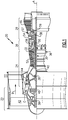
- FIG. 1 schematically illustrates a gas turbine engine 20.
- the gas turbine engine 20 is disclosed herein as a two-spool turbofan that generally incorporates a fan section 22, a compressor section 24, a combustor section 26 and a turbine section 28.
- Alternative engines might include an augmentor section (not shown) among other systems or features.
- the fan section 22 drives air along a bypass flow path B in a bypass duct defined within a nacelle 15, and also drives air along a core flow path C for compression and communication into the combustor section 26 then expansion through the turbine section 28.
- the exemplary engine 20 generally includes a low speed spool 30 and a high speed spool 32 mounted for rotation about an engine central longitudinal axis A relative to an engine static structure 36 via several bearing systems 38. It should be understood that various bearing systems 38 at various locations may alternatively or additionally be provided, and the location of bearing systems 38 may be varied as appropriate to the application.
- the low speed spool 30 generally includes an inner shaft 40 that interconnects a fan 42, a first (or low) pressure compressor 44 and a first (or low) pressure turbine 46.
- the inner shaft 40 is connected to the fan 42 through a speed change mechanism, which in exemplary gas turbine engine 20 is illustrated as a geared architecture 48 to drive the fan 42 at a lower speed than the low speed spool 30.
- the high speed spool 32 includes an outer shaft 50 that interconnects a second (or high) pressure compressor 52 and a second (or high) pressure turbine 54.
- a combustor 56 is arranged in exemplary gas turbine 20 between the high pressure compressor 52 and the high pressure turbine 54.
- a mid-turbine frame 57 of the engine static structure 36 is arranged generally between the high pressure turbine 54 and the low pressure turbine 46.
- the mid-turbine frame 57 further supports bearing systems 38 in the turbine section 28.
- the inner shaft 40 and the outer shaft 50 are concentric and rotate via bearing systems 38 about the engine central longitudinal axis A which is collinear with their longitudinal axes.
- the core airflow is compressed by the low pressure compressor 44 then the high pressure compressor 52, mixed and burned with fuel in the combustor 56, then expanded over the high pressure turbine 54 and low pressure turbine 46.
- the mid-turbine frame 57 includes airfoils 59 which are in the core airflow path C.
- the turbines 46, 54 rotationally drive the respective low speed spool 30 and high speed spool 32 in response to the expansion.
- gear system 48 may be located aft of combustor section 26 or even aft of turbine section 28, and fan section 22 may be positioned forward or aft of the location of gear system 48.
- the engine 20 in one example is a high-bypass geared aircraft engine.
- the engine 20 bypass ratio is greater than about six, with an example embodiment being greater than about ten
- the geared architecture 48 is an epicyclic gear train, such as a planetary gear system or other gear system, with a gear reduction ratio of greater than about 2.3 and the low pressure turbine 46 has a pressure ratio that is greater than about five.
- the engine 20 bypass ratio is greater than about ten
- the fan diameter is significantly larger than that of the low pressure compressor 44
- the low pressure turbine 46 has a pressure ratio that is greater than about five.
- Low pressure turbine 46 pressure ratio is pressure measured prior to inlet of low pressure turbine 46 as related to the pressure at the outlet of the low pressure turbine 46 prior to an exhaust nozzle.
- the geared architecture 48 may be an epicycle gear train, such as a planetary gear system or other gear system, with a gear reduction ratio of greater than about 2.3:1. It should be understood, however, that the above parameters are only exemplary of one embodiment of a geared architecture engine and that the present invention is applicable to other gas turbine engines including direct drive turbofans.
- the fan section 22 of the engine 20 is designed for a particular flight condition -- typically cruise at about 0.8 Mach and about 35,000 feet (10,668 meters).
- the flight condition of 0.8 Mach and 35,000 ft (10,668 meters), with the engine at its best fuel consumption - also known as "bucket cruise Thrust Specific Fuel Consumption ('TSFC')" - is the industry standard parameter of lbm of fuel being burned divided by lbf of thrust the engine produces at that minimum point.
- "Low fan pressure ratio” is the pressure ratio across the fan blade alone, without a Fan Exit Guide Vane (“FEGV”) system.
- the low fan pressure ratio as disclosed herein according to one non-limiting embodiment is less than about 1.45.
- the "Low corrected fan tip speed” as disclosed herein according to one non-limiting embodiment is less than about 1150 ft / second (350.5 meters/second).
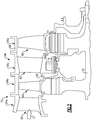
- first and second arrays 54a, 54c of circumferentially spaced fixed vanes 60, 62 are axially spaced apart from one another.
- a first stage array 54b of circumferentially spaced turbine blades 64 is arranged axially between the first and second fixed vane arrays 54a, 54c.
- a second stage array 54d of circumferentially spaced turbine blades 66 is arranged aft of the second array 54c of fixed vanes 62.
- the turbine blades each include a tip adjacent to a blade outer air seal 68 of a case structure 70, which is part of the engine static structure 36.
- the first and second stage arrays 54a, 54c of turbine vanes and first and second stage arrays 54b, 54d of turbine blades are arranged within the core flow path C and are operatively connected to the high speed spool 32.
- Figure 3 illustrates a secondary flow F from a cooling source 71, which may be provided by a stage of the compressor section 24, through the high pressure turbine section 54. It should be understood that the disclosed cooling configuration may be used in other sections of the engine.
- the vane 60 is supported with respect to the case structure 70 via a vane support 76 attached to the case structure 70.
- the vane 60 includes forward and aft rails 72, 74 between forming a first cavity 88 that is enclosed by a first seal 80 provided between the vane support 76 and the aft rail 74.
- the case structure 70 includes a BOAS support 78 to which the BOAS 68 is mounted.
- a second seal 82 is provided between the BOAS support 78 and the aft rail 74.
- a second cavity 92 is provided between the case structure 70 and the first and second seal 80, 82.
- a third cavity 93 is provided between case structure 70 and the BOAS support 78, and a fourth cavity 94 is provided between the BOAS support 78 and the BOAS 68.
- Third and fourth seals 84, 86 are respectively provided between the second vane 62 and the case structure 70 and the BOAS 68 to provide a fifth cavity 98. More or few components may be used that shown, and the components may be configured differently than illustrated.
- the secondary flow F provided from the cooling source 71 flows through the first cavity 88 through a metering hole 90 in the vane support 76 to the second cavity 92.
- the secondary flow F then flows through the BOAS support 78 into the third cavity 93 and through an aperture 95 in the BOAS support 78 to the fourth cavity 94.
- a gap 96 fluidly interconnects the fourth cavity 94 to the fifth cavity 98.
- the metering hole 90 may be provided elsewhere along the secondary flow path.
- the secondary flow F may be fed from the various cavities to passages in components within the high pressure turbine section 54, for example, impingement holes and feed holes in vane 60, BOAS 68, vane 62 and/or other components. These passages are relatively small in size and are susceptible to becoming plugged with debris over time, which can result in burning of the component.
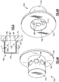
- a strainer 100 is arranged over the metering hole 90 to strain large debris from the secondary flow F, which may accumulate within the secondary flow path or clog the passages.
- the strainer 100 includes a flange 102, which is annular in shape in the example, providing an outlet opening 106.
- a cup 104 is provided by a cylinder that is closed at one end extends from the flange 102 and provides a pocket 110 that is in fluid communication with the opening 106. Other shapes may be used to provide the strainer.
- multiple inlet holes 108 are provided about a periphery of the cup 104 and are directed at one another. Individual hole size is selected based upon debris size to be strained.
- the holes 108 provide a total area that is larger than wither of the opening 106 and the metering hole 90 such that the metering hole 90 provides the fluid metering downstream from the first cavity 88 along secondary flow path rather than the holes 108.
- the strainer 100 reduces the collection of particles by reducing the impingement velocity as well as physically straining any debris with the holes 108.
- the strainer 100 is mounted to a surface where the debris will collect in an acceptable area, for example, the first cavity 88.
- the vane support 76 provides a radially extending annular wall providing a planar surface to which the flange 102 of the strainer 100 is mounted in the axial direction. Debris can safely collect near the aft rail 74 beneath the first spring 80 and/or along the vane support 76 at the bottom of the annulus.
- the flange 102 is also planar and is secured to the vane support 76 over the metering hole 90 by brazing or welding, for example.
Landscapes
- Engineering & Computer Science (AREA)
- Chemical & Material Sciences (AREA)
- Combustion & Propulsion (AREA)
- Chemical Kinetics & Catalysis (AREA)
- Mechanical Engineering (AREA)
- General Engineering & Computer Science (AREA)
- Physics & Mathematics (AREA)
- Geometry (AREA)
- Turbine Rotor Nozzle Sealing (AREA)
Abstract
Description
- This disclosure relates to a component and configuration for removing debris from a cooling flow in a gas turbine engine.
- A gas turbine engine typically includes a fan section, a compressor section, a combustor section and a turbine section. Air entering the compressor section is compressed and delivered into the combustor section where it is mixed with fuel and ignited to generate a high-speed exhaust gas flow. The high-speed exhaust gas flow expands through the turbine section to drive the compressor and the fan section. The compressor section typically includes low and high pressure compressors, and the turbine section includes low and high pressure turbines.
- Typical compressor and turbine sections include fixed vanes and rotating blades that seal with respect to blade outer air seals (BOAS). A secondary flow system is provided between the BOAS and vanes and the high pressure turbine case structure. This flow is used to cool various components within the very hot high pressure turbine section during engine operation. Some of the cooling passages in components within the high pressure turbine are relatively small and are fed by the secondary cooling flow. Debris carried by the secondary flow can clog these passages.
- An erosion energy dissipater has been used in the secondary flow path to choke the flow and reduce the velocity of any debris carried by the secondary flow. One end of the dissipater has a large diameter outlet orifice, and the other end has multiple inlet orifices, which have a total area that is much smaller than a large diameter outlet orifice. The relative total areas of the inlet and outlet orifices reduce the energy of the debris in the secondary flow when passing through the dissipater.
- A gas turbine engine according to one disclosed non-limiting embodiment includes an engine static structure that provides a flow path. A metering hole is provided in the engine static structure. A strainer is arranged over the metering hole. The strainer includes multiple holes that have a total area that is greater than a metering hole area.
- In an embodiment of any of the above, a turbine section provides a secondary flow path corresponding the flow path. The secondary flow path is provided between a case structure and a vane and a blade outer air seal.
- In a further embodiment of any of the above, one of the vane, the case structure and the blade outer air seal provide the metering hole.
- In a further embodiment of any of the above, the case structure includes a vane support to which the vane is mounted. The vane support provides the metering hole.
- In a further embodiment of any of the above, the vane includes an aft rail. A seal is provided between the vane support and the aft rail to provide a first cavity. The strainer is provided within the first cavity.
- In a further embodiment of any of the above, the vane support includes a radially extending planar annular wall. The metering hole is provided in the wall.
- In a further embodiment of any of the above, a second seal is provided between the aft rail and a blade outer air seal support to which the blade outer air seal is mounted. A second cavity is provided between the case structure and the first and second seals. The strainer is fluidly arranged between the first and second cavities.
- In a further embodiment of any of the above, the strainer is secured to the wall.
- In a further embodiment of any of the above, the strainer includes a flange that has an opening. A cup extends from the flange and provides a pocket. The holes are provided in the cup.
- In a further embodiment of any of the above, the flange is planar and is secured to the engine static structure by brazing or welding.
- In a further embodiment of any of the above, the total area of the holes is greater than the opening.
- In a further embodiment of any of the above, the cup is cylindrical and the holes are provided about a periphery of the cup.
- In another exemplary embodiment, a method cooling a gas turbine engine includes flowing fluid through a strainer that has inlet holes with a larger total area than a metering hole over which the strainer is secured.
- In a further embodiment of any of the above, the flowing step includes providing a secondary flow to a high pressure turbine between a case structure and a vane and a blade outer air seal.
- In a further embodiment of any of the above, the strainer extends in an axial direction along which the second flow travels.
- In a further embodiment of any of the above, the flange has an opening and a cup extends from the flange and provides a pocket. The holes are provided in a periphery of the cup and the total area is greater than and opening area. The flange is planar and annular in shape. An end of the cup is closed.
- A flow strainer for a gas turbine engine according to another disclosed non-limiting embodiment includes a flange that has an opening. A cup extends from the flange and provides a pocket. Multiple holes are provided in the cup and have a total area that is greater than and opening area.
- In an embodiment of any of the above, the flange is planar and annular in shape.
- In a further embodiment of any of the above, the cup is cylindrical and the holes are provided about a periphery of the cup.
- In a further embodiment of any of the above, an end of the cup is closed.
- The disclosure can be further understood by reference to the following detailed description when considered in connection with the accompanying drawings wherein:
-
Figure 1 schematically illustrates a gas turbine engine embodiment. -
Figure 2 is a schematic view of one example high pressure turbine section. -
Figure 3 is an enlarged view of the high pressure turbine section illustrating a secondary flow there through. -
Figures 4A and 4B are perspective views of a strainer used to filter large debris in the secondary flow. -
Figure 5 is a cross-sectional view through the strainer shown inFigures 4A and 4B . - The embodiments, examples and alternatives of the preceding paragraphs, the claims, or the following description and drawings, including any of their various aspects or respective individual features, may be taken independently or in any combination. Features described in connection with one embodiment are applicable to all embodiments, unless such features are incompatible.
-
Figure 1 schematically illustrates agas turbine engine 20. Thegas turbine engine 20 is disclosed herein as a two-spool turbofan that generally incorporates afan section 22, acompressor section 24, acombustor section 26 and aturbine section 28. Alternative engines might include an augmentor section (not shown) among other systems or features. Thefan section 22 drives air along a bypass flow path B in a bypass duct defined within a nacelle 15, and also drives air along a core flow path C for compression and communication into thecombustor section 26 then expansion through theturbine section 28. Although depicted as a two-spool turbofan gas turbine engine in the disclosed non-limiting embodiment, it should be understood that the concepts described herein are not limited to use with two-spool turbofans as the teachings may be applied to other types of turbine engines including three-spool architectures. - The
exemplary engine 20 generally includes alow speed spool 30 and ahigh speed spool 32 mounted for rotation about an engine central longitudinal axis A relative to an enginestatic structure 36 viaseveral bearing systems 38. It should be understood that various bearingsystems 38 at various locations may alternatively or additionally be provided, and the location of bearingsystems 38 may be varied as appropriate to the application. - The
low speed spool 30 generally includes aninner shaft 40 that interconnects afan 42, a first (or low)pressure compressor 44 and a first (or low)pressure turbine 46. Theinner shaft 40 is connected to thefan 42 through a speed change mechanism, which in exemplarygas turbine engine 20 is illustrated as a gearedarchitecture 48 to drive thefan 42 at a lower speed than thelow speed spool 30. Thehigh speed spool 32 includes anouter shaft 50 that interconnects a second (or high)pressure compressor 52 and a second (or high)pressure turbine 54. Acombustor 56 is arranged inexemplary gas turbine 20 between thehigh pressure compressor 52 and thehigh pressure turbine 54. A mid-turbine frame 57 of the enginestatic structure 36 is arranged generally between thehigh pressure turbine 54 and thelow pressure turbine 46. The mid-turbine frame 57 furthersupports bearing systems 38 in theturbine section 28. Theinner shaft 40 and theouter shaft 50 are concentric and rotate via bearingsystems 38 about the engine central longitudinal axis A which is collinear with their longitudinal axes. - The core airflow is compressed by the
low pressure compressor 44 then thehigh pressure compressor 52, mixed and burned with fuel in thecombustor 56, then expanded over thehigh pressure turbine 54 andlow pressure turbine 46. The mid-turbine frame 57 includesairfoils 59 which are in the core airflow path C. Theturbines low speed spool 30 andhigh speed spool 32 in response to the expansion. It will be appreciated that each of the positions of thefan section 22,compressor section 24,combustor section 26,turbine section 28, and fandrive gear system 48 may be varied. For example,gear system 48 may be located aft ofcombustor section 26 or even aft ofturbine section 28, andfan section 22 may be positioned forward or aft of the location ofgear system 48. - The
engine 20 in one example is a high-bypass geared aircraft engine. In a further example, theengine 20 bypass ratio is greater than about six, with an example embodiment being greater than about ten, the gearedarchitecture 48 is an epicyclic gear train, such as a planetary gear system or other gear system, with a gear reduction ratio of greater than about 2.3 and thelow pressure turbine 46 has a pressure ratio that is greater than about five. In one disclosed embodiment, theengine 20 bypass ratio is greater than about ten, the fan diameter is significantly larger than that of thelow pressure compressor 44, and thelow pressure turbine 46 has a pressure ratio that is greater than about five.Low pressure turbine 46 pressure ratio is pressure measured prior to inlet oflow pressure turbine 46 as related to the pressure at the outlet of thelow pressure turbine 46 prior to an exhaust nozzle. The gearedarchitecture 48 may be an epicycle gear train, such as a planetary gear system or other gear system, with a gear reduction ratio of greater than about 2.3:1. It should be understood, however, that the above parameters are only exemplary of one embodiment of a geared architecture engine and that the present invention is applicable to other gas turbine engines including direct drive turbofans. - A significant amount of thrust is provided by the bypass flow B due to the high bypass ratio. The
fan section 22 of theengine 20 is designed for a particular flight condition -- typically cruise at about 0.8 Mach and about 35,000 feet (10,668 meters). The flight condition of 0.8 Mach and 35,000 ft (10,668 meters), with the engine at its best fuel consumption - also known as "bucket cruise Thrust Specific Fuel Consumption ('TSFC')" - is the industry standard parameter of lbm of fuel being burned divided by lbf of thrust the engine produces at that minimum point. "Low fan pressure ratio" is the pressure ratio across the fan blade alone, without a Fan Exit Guide Vane ("FEGV") system. The low fan pressure ratio as disclosed herein according to one non-limiting embodiment is less than about 1.45. "Low corrected fan tip speed" is the actual fan tip speed in ft/sec divided by an industry standard temperature correction of [(Tram °R) / (518.7 °R)]0.5 (where °R = K x 9/5). The "Low corrected fan tip speed" as disclosed herein according to one non-limiting embodiment is less than about 1150 ft / second (350.5 meters/second). - Referring to
Figure 2 , a cross-sectional view through the highpressure turbine section 54 is illustrated. In the example highpressure turbine section 54, first andsecond arrays vanes first stage array 54b of circumferentially spacedturbine blades 64 is arranged axially between the first and second fixedvane arrays second stage array 54d of circumferentially spacedturbine blades 66 is arranged aft of thesecond array 54c of fixedvanes 62. - The turbine blades each include a tip adjacent to a blade
outer air seal 68 of acase structure 70, which is part of the enginestatic structure 36. The first andsecond stage arrays second stage arrays high speed spool 32. -
Figure 3 illustrates a secondary flow F from a coolingsource 71, which may be provided by a stage of thecompressor section 24, through the highpressure turbine section 54. It should be understood that the disclosed cooling configuration may be used in other sections of the engine. In the example, thevane 60 is supported with respect to thecase structure 70 via avane support 76 attached to thecase structure 70. Thevane 60 includes forward andaft rails first cavity 88 that is enclosed by afirst seal 80 provided between thevane support 76 and theaft rail 74. Thecase structure 70 includes aBOAS support 78 to which theBOAS 68 is mounted. Asecond seal 82 is provided between theBOAS support 78 and theaft rail 74. Asecond cavity 92 is provided between thecase structure 70 and the first andsecond seal - A
third cavity 93 is provided betweencase structure 70 and theBOAS support 78, and afourth cavity 94 is provided between theBOAS support 78 and theBOAS 68. Third andfourth seals second vane 62 and thecase structure 70 and theBOAS 68 to provide afifth cavity 98. More or few components may be used that shown, and the components may be configured differently than illustrated. - In operation, the secondary flow F provided from the cooling
source 71 flows through thefirst cavity 88 through ametering hole 90 in thevane support 76 to thesecond cavity 92. The secondary flow F then flows through theBOAS support 78 into thethird cavity 93 and through anaperture 95 in theBOAS support 78 to thefourth cavity 94. Agap 96 fluidly interconnects thefourth cavity 94 to thefifth cavity 98. Themetering hole 90 may be provided elsewhere along the secondary flow path. - The secondary flow F may be fed from the various cavities to passages in components within the high
pressure turbine section 54, for example, impingement holes and feed holes invane 60,BOAS 68,vane 62 and/or other components. These passages are relatively small in size and are susceptible to becoming plugged with debris over time, which can result in burning of the component. - A
strainer 100 is arranged over themetering hole 90 to strain large debris from the secondary flow F, which may accumulate within the secondary flow path or clog the passages. Referring toFigures 4A-5 , thestrainer 100 includes aflange 102, which is annular in shape in the example, providing anoutlet opening 106. Acup 104 is provided by a cylinder that is closed at one end extends from theflange 102 and provides apocket 110 that is in fluid communication with theopening 106. Other shapes may be used to provide the strainer. In the example, multiple inlet holes 108 are provided about a periphery of thecup 104 and are directed at one another. Individual hole size is selected based upon debris size to be strained. In one example, theholes 108 provide a total area that is larger than wither of theopening 106 and themetering hole 90 such that themetering hole 90 provides the fluid metering downstream from thefirst cavity 88 along secondary flow path rather than theholes 108. Thestrainer 100 reduces the collection of particles by reducing the impingement velocity as well as physically straining any debris with theholes 108. - The
strainer 100 is mounted to a surface where the debris will collect in an acceptable area, for example, thefirst cavity 88. In the example, thevane support 76 provides a radially extending annular wall providing a planar surface to which theflange 102 of thestrainer 100 is mounted in the axial direction. Debris can safely collect near theaft rail 74 beneath thefirst spring 80 and/or along thevane support 76 at the bottom of the annulus. Theflange 102 is also planar and is secured to thevane support 76 over themetering hole 90 by brazing or welding, for example. - It should also be understood that although a particular component arrangement is disclosed in the illustrated embodiment, other arrangements will benefit herefrom. Although particular step sequences are shown, described, and claimed, it should be understood that steps may be performed in any order, separated or combined unless otherwise indicated and will still benefit from the present invention.
- Although the different examples have specific components shown in the illustrations, embodiments of this invention are not limited to those particular combinations. It is possible to use some of the components or features from one of the examples in combination with features or components from another one of the examples.
- Although an example embodiment has been disclosed, a worker of ordinary skill in this art would recognize that certain modifications would come within the scope of the claims. For that reason, the following claims should be studied to determine their true scope and content.
Claims (15)
- A gas turbine engine (20) comprising:an engine static structure (36) providing a flow path;a metering hole (90) provided in the engine static structure (36); anda strainer (100) arranged over the metering hole (90), the strainer (100) including multiple holes (108) having a total area that is greater than a metering hole (90) area.
- The gas turbine engine (20) of claim 1, comprising a turbine section (54) that provides a secondary flow path (F) between a case structure (70), and a vane (60, 62) and a blade outer air seal (68).
- The gas turbine engine (20) of claim 2, wherein one of the vane (60, 62), the case structure (70) and the blade outer air seal (68) provide the metering hole (90).
- The gas turbine engine (20) of claim 2 or 3, wherein the case structure (70) includes a vane support (76) to which the vane is mounted, and the vane support (76) provides the metering hole (90).
- The gas turbine engine (20) of any of claims 2 to 4, wherein the vane (60, 62) includes an aft rail (74), a first seal (80) is provided between the vane support (76) and the aft rail (74) to provide a first cavity (88), and the strainer (100) is provided within the first cavity (88).
- The gas turbine engine (20) of claim 5, wherein a second seal (82) is provided between the aft rail (74) and a blade outer air seal support (78) to which the blade outer air seal (68) is mounted, a second cavity (92) is provided between the case structure (70) and the first (80) and second (82) seals, and the strainer (100) is fluidly arranged between the first (88) and second (92) cavities.
- The gas turbine engine (20) of claim 4, 5 or 6, wherein the vane support (76) includes a radially extending planar annular wall, and the metering hole (90) is provided in the wall, optionally wherein the strainer (100) is secured to the wall.
- The gas turbine engine (20) of any preceding claim, wherein the strainer (100) includes a flange (102) having an opening (106), a cup (104) extends from the flange (102) and provides a pocket (110), and the holes (108) are provided in the cup (104), optionally wherein the cup (104) is cylindrical and the holes (108) are provided about a periphery of the cup (104).
- The gas turbine engine (20) of claim 8, wherein the flange (102) is planar and secured to the engine static structure (36) by brazing or welding.
- The gas turbine engine (20) of claim 8 or 9, wherein the total area of the holes (108) is greater than the opening (106).
- A method cooling a gas turbine engine (20), comprising flowing fluid through a strainer (100) having inlet holes (108) with a larger total area than a metering hole (90) over which the strainer (100) is secured, optionally wherein the flowing step includes providing a secondary flow (F) to a high pressure turbine (54) between a case structure (70) and a vane (60, 62) and a blade outer air seal (68).
- The method of claim 11, wherein the strainer (100) extends in an axial direction along which the second flow (F) travels, optionally wherein a flange (102) has an opening (106), a cup (104) extends from the flange (102) and provides a pocket (110), the inlet holes (108) are provided in a periphery of the cup (104), the total area of the inlet holes (108) is greater than an area of the opening (106), the flange (102) is planar and annular in shape, and an end of the cup (104) is closed.
- A flow strainer (100) for a gas turbine engine (20) comprising:a flange (102) having an opening (106); anda cup (104) extending from the flange (102) and providing a pocket (110), wherein multiple holes (108) are provided in the cup (104) and have a total area that is greater than an opening (106) area.
- The strainer (100) of claim 13, wherein the flange (102) is planar and annular in shape.
- The strainer (100) of claim 13 or 14, wherein the cup (104) is cylindrical and the holes (108) are provided about a periphery of the cup (104), optionally wherein an end of the cup (104) is closed.
Applications Claiming Priority (1)
| Application Number | Priority Date | Filing Date | Title |
|---|---|---|---|
| US15/627,809 US10427075B2 (en) | 2017-06-20 | 2017-06-20 | Debris strainer for gas turbine engine cooling flow |
Publications (2)
| Publication Number | Publication Date |
|---|---|
| EP3428411A1 true EP3428411A1 (en) | 2019-01-16 |
| EP3428411B1 EP3428411B1 (en) | 2021-06-02 |
Family
ID=62715919
Family Applications (1)
| Application Number | Title | Priority Date | Filing Date |
|---|---|---|---|
| EP18178792.0A Active EP3428411B1 (en) | 2017-06-20 | 2018-06-20 | Gas turbine engine and corresponding method of cooling |
Country Status (2)
| Country | Link |
|---|---|
| US (1) | US10427075B2 (en) |
| EP (1) | EP3428411B1 (en) |
Cited By (3)
| Publication number | Priority date | Publication date | Assignee | Title |
|---|---|---|---|---|
| EP3597875A1 (en) * | 2018-07-18 | 2020-01-22 | United Technologies Corporation | Debris separator for a gas turbine engine |
| WO2021001615A1 (en) * | 2019-07-04 | 2021-01-07 | Safran Aircraft Engines | Improved aircraft turbine shroud cooling device |
| EP4556690A1 (en) * | 2023-11-20 | 2025-05-21 | RTX Corporation | Cyclonic separator for a gas turbine seal support |
Families Citing this family (2)
| Publication number | Priority date | Publication date | Assignee | Title |
|---|---|---|---|---|
| JP6563312B2 (en) * | 2015-11-05 | 2019-08-21 | 川崎重工業株式会社 | Extraction structure of gas turbine engine |
| US11415001B1 (en) * | 2021-03-11 | 2022-08-16 | General Electric Company | Cooling hole filter configuration |
Citations (4)
| Publication number | Priority date | Publication date | Assignee | Title |
|---|---|---|---|---|
| US20040221720A1 (en) * | 2001-10-23 | 2004-11-11 | Gordon Anderson | Device for filtering particles out of a coolant flow in a turbo machine |
| US20070048122A1 (en) * | 2005-08-30 | 2007-03-01 | United Technologies Corporation | Debris-filtering technique for gas turbine engine component air cooling system |
| EP2093384A2 (en) * | 2008-02-24 | 2009-08-26 | United Technologies Corporation | Filter system for blade outer air seal |
| US20130192257A1 (en) * | 2010-03-18 | 2013-08-01 | General Electric Company | Turbine shroud hanger with debris filter |
Family Cites Families (3)
| Publication number | Priority date | Publication date | Assignee | Title |
|---|---|---|---|---|
| US4668164A (en) * | 1984-12-21 | 1987-05-26 | United Technologies Corporation | Coolable stator assembly for a gas turbine engine |
| US6019575A (en) | 1997-09-12 | 2000-02-01 | United Technologies Corporation | Erosion energy dissipater |
| US7770375B2 (en) | 2006-02-09 | 2010-08-10 | United Technologies Corporation | Particle collector for gas turbine engine |
-
2017
- 2017-06-20 US US15/627,809 patent/US10427075B2/en active Active
-
2018
- 2018-06-20 EP EP18178792.0A patent/EP3428411B1/en active Active
Patent Citations (4)
| Publication number | Priority date | Publication date | Assignee | Title |
|---|---|---|---|---|
| US20040221720A1 (en) * | 2001-10-23 | 2004-11-11 | Gordon Anderson | Device for filtering particles out of a coolant flow in a turbo machine |
| US20070048122A1 (en) * | 2005-08-30 | 2007-03-01 | United Technologies Corporation | Debris-filtering technique for gas turbine engine component air cooling system |
| EP2093384A2 (en) * | 2008-02-24 | 2009-08-26 | United Technologies Corporation | Filter system for blade outer air seal |
| US20130192257A1 (en) * | 2010-03-18 | 2013-08-01 | General Electric Company | Turbine shroud hanger with debris filter |
Cited By (6)
| Publication number | Priority date | Publication date | Assignee | Title |
|---|---|---|---|---|
| EP3597875A1 (en) * | 2018-07-18 | 2020-01-22 | United Technologies Corporation | Debris separator for a gas turbine engine |
| US10584613B2 (en) | 2018-07-18 | 2020-03-10 | United Technologies Corporation | Necked debris separator for a gas turbine engine |
| WO2021001615A1 (en) * | 2019-07-04 | 2021-01-07 | Safran Aircraft Engines | Improved aircraft turbine shroud cooling device |
| FR3098238A1 (en) * | 2019-07-04 | 2021-01-08 | Safran Aircraft Engines | improved aircraft turbine ring cooling system |
| US11795838B2 (en) | 2019-07-04 | 2023-10-24 | Safran Aircraft Engines | Aircraft turbine shroud cooling device |
| EP4556690A1 (en) * | 2023-11-20 | 2025-05-21 | RTX Corporation | Cyclonic separator for a gas turbine seal support |
Also Published As
| Publication number | Publication date |
|---|---|
| US20180361284A1 (en) | 2018-12-20 |
| EP3428411B1 (en) | 2021-06-02 |
| US10427075B2 (en) | 2019-10-01 |
Similar Documents
| Publication | Publication Date | Title |
|---|---|---|
| US11092025B2 (en) | Gas turbine engine with dove-tailed TOBI vane | |
| EP3734018A1 (en) | Seal for a gas turbine engine | |
| EP3428411B1 (en) | Gas turbine engine and corresponding method of cooling | |
| EP3543464B1 (en) | Dual cavity baffle | |
| EP3039264B1 (en) | Gas turbine engine diffuser cooling and mixing arrangement | |
| EP3502440B1 (en) | Gas turbine engine component assembly | |
| EP3246523B1 (en) | Cooled blade outer air seal | |
| EP3061910B1 (en) | Gas turbine engine airfoil and corresponding method of forming | |
| US10465542B2 (en) | Gas turbine engine turbine vane baffle and serpentine cooling passage | |
| EP3190266B1 (en) | Gas turbine engine comprising a rotor hub seal | |
| EP3514332A1 (en) | Dual-wall impingement cavity for components of gas turbine engines | |
| EP3708794B1 (en) | Dual radial scoop oil delivery system | |
| US11976566B2 (en) | Fatigue resistant blade outer air seal | |
| EP3045666B1 (en) | Airfoil platform with cooling feed orifices | |
| EP3495613B1 (en) | Cooled gas turbine engine component | |
| US20180038236A1 (en) | Gas turbine engine stator vane baffle arrangement | |
| EP3748133B1 (en) | Fatigue resistant blade outer air seal | |
| US11199104B2 (en) | Seal anti-rotation | |
| US12516610B2 (en) | Oil passage built into bearing compartment spring | |
| US20160160652A1 (en) | Cooled pocket in a turbine vane platform | |
| EP3581762B1 (en) | Platform cooling arrangement for a gas turbine engine |
Legal Events
| Date | Code | Title | Description |
|---|---|---|---|
| PUAI | Public reference made under article 153(3) epc to a published international application that has entered the european phase |
Free format text: ORIGINAL CODE: 0009012 |
|
| STAA | Information on the status of an ep patent application or granted ep patent |
Free format text: STATUS: THE APPLICATION HAS BEEN PUBLISHED |
|
| AK | Designated contracting states |
Kind code of ref document: A1 Designated state(s): AL AT BE BG CH CY CZ DE DK EE ES FI FR GB GR HR HU IE IS IT LI LT LU LV MC MK MT NL NO PL PT RO RS SE SI SK SM TR |
|
| AX | Request for extension of the european patent |
Extension state: BA ME |
|
| STAA | Information on the status of an ep patent application or granted ep patent |
Free format text: STATUS: REQUEST FOR EXAMINATION WAS MADE |
|
| 17P | Request for examination filed |
Effective date: 20190716 |
|
| RBV | Designated contracting states (corrected) |
Designated state(s): AL AT BE BG CH CY CZ DE DK EE ES FI FR GB GR HR HU IE IS IT LI LT LU LV MC MK MT NL NO PL PT RO RS SE SI SK SM TR |
|
| STAA | Information on the status of an ep patent application or granted ep patent |
Free format text: STATUS: EXAMINATION IS IN PROGRESS |
|
| 17Q | First examination report despatched |
Effective date: 20200430 |
|
| GRAP | Despatch of communication of intention to grant a patent |
Free format text: ORIGINAL CODE: EPIDOSNIGR1 |
|
| STAA | Information on the status of an ep patent application or granted ep patent |
Free format text: STATUS: GRANT OF PATENT IS INTENDED |
|
| INTG | Intention to grant announced |
Effective date: 20201215 |
|
| RAP1 | Party data changed (applicant data changed or rights of an application transferred) |
Owner name: RAYTHEON TECHNOLOGIES CORPORATION |
|
| GRAS | Grant fee paid |
Free format text: ORIGINAL CODE: EPIDOSNIGR3 |
|
| GRAA | (expected) grant |
Free format text: ORIGINAL CODE: 0009210 |
|
| STAA | Information on the status of an ep patent application or granted ep patent |
Free format text: STATUS: THE PATENT HAS BEEN GRANTED |
|
| REG | Reference to a national code |
Ref country code: CH Ref legal event code: EP |
|
| AK | Designated contracting states |
Kind code of ref document: B1 Designated state(s): AL AT BE BG CH CY CZ DE DK EE ES FI FR GB GR HR HU IE IS IT LI LT LU LV MC MK MT NL NO PL PT RO RS SE SI SK SM TR |
|
| REG | Reference to a national code |
Ref country code: GB Ref legal event code: FG4D |
|
| REG | Reference to a national code |
Ref country code: AT Ref legal event code: REF Ref document number: 1398628 Country of ref document: AT Kind code of ref document: T Effective date: 20210615 |
|
| REG | Reference to a national code |
Ref country code: IE Ref legal event code: FG4D |
|
| REG | Reference to a national code |
Ref country code: DE Ref legal event code: R096 Ref document number: 602018017901 Country of ref document: DE |
|
| REG | Reference to a national code |
Ref country code: LT Ref legal event code: MG9D |
|
| PG25 | Lapsed in a contracting state [announced via postgrant information from national office to epo] |
Ref country code: FI Free format text: LAPSE BECAUSE OF FAILURE TO SUBMIT A TRANSLATION OF THE DESCRIPTION OR TO PAY THE FEE WITHIN THE PRESCRIBED TIME-LIMIT Effective date: 20210602 Ref country code: HR Free format text: LAPSE BECAUSE OF FAILURE TO SUBMIT A TRANSLATION OF THE DESCRIPTION OR TO PAY THE FEE WITHIN THE PRESCRIBED TIME-LIMIT Effective date: 20210602 Ref country code: LT Free format text: LAPSE BECAUSE OF FAILURE TO SUBMIT A TRANSLATION OF THE DESCRIPTION OR TO PAY THE FEE WITHIN THE PRESCRIBED TIME-LIMIT Effective date: 20210602 Ref country code: BG Free format text: LAPSE BECAUSE OF FAILURE TO SUBMIT A TRANSLATION OF THE DESCRIPTION OR TO PAY THE FEE WITHIN THE PRESCRIBED TIME-LIMIT Effective date: 20210902 |
|
| REG | Reference to a national code |
Ref country code: NL Ref legal event code: MP Effective date: 20210602 |
|
| REG | Reference to a national code |
Ref country code: AT Ref legal event code: MK05 Ref document number: 1398628 Country of ref document: AT Kind code of ref document: T Effective date: 20210602 |
|
| PG25 | Lapsed in a contracting state [announced via postgrant information from national office to epo] |
Ref country code: GR Free format text: LAPSE BECAUSE OF FAILURE TO SUBMIT A TRANSLATION OF THE DESCRIPTION OR TO PAY THE FEE WITHIN THE PRESCRIBED TIME-LIMIT Effective date: 20210903 Ref country code: RS Free format text: LAPSE BECAUSE OF FAILURE TO SUBMIT A TRANSLATION OF THE DESCRIPTION OR TO PAY THE FEE WITHIN THE PRESCRIBED TIME-LIMIT Effective date: 20210602 Ref country code: SE Free format text: LAPSE BECAUSE OF FAILURE TO SUBMIT A TRANSLATION OF THE DESCRIPTION OR TO PAY THE FEE WITHIN THE PRESCRIBED TIME-LIMIT Effective date: 20210602 Ref country code: LV Free format text: LAPSE BECAUSE OF FAILURE TO SUBMIT A TRANSLATION OF THE DESCRIPTION OR TO PAY THE FEE WITHIN THE PRESCRIBED TIME-LIMIT Effective date: 20210602 Ref country code: NO Free format text: LAPSE BECAUSE OF FAILURE TO SUBMIT A TRANSLATION OF THE DESCRIPTION OR TO PAY THE FEE WITHIN THE PRESCRIBED TIME-LIMIT Effective date: 20210902 Ref country code: PL Free format text: LAPSE BECAUSE OF FAILURE TO SUBMIT A TRANSLATION OF THE DESCRIPTION OR TO PAY THE FEE WITHIN THE PRESCRIBED TIME-LIMIT Effective date: 20210602 |
|
| PG25 | Lapsed in a contracting state [announced via postgrant information from national office to epo] |
Ref country code: SK Free format text: LAPSE BECAUSE OF FAILURE TO SUBMIT A TRANSLATION OF THE DESCRIPTION OR TO PAY THE FEE WITHIN THE PRESCRIBED TIME-LIMIT Effective date: 20210602 Ref country code: SM Free format text: LAPSE BECAUSE OF FAILURE TO SUBMIT A TRANSLATION OF THE DESCRIPTION OR TO PAY THE FEE WITHIN THE PRESCRIBED TIME-LIMIT Effective date: 20210602 Ref country code: EE Free format text: LAPSE BECAUSE OF FAILURE TO SUBMIT A TRANSLATION OF THE DESCRIPTION OR TO PAY THE FEE WITHIN THE PRESCRIBED TIME-LIMIT Effective date: 20210602 Ref country code: ES Free format text: LAPSE BECAUSE OF FAILURE TO SUBMIT A TRANSLATION OF THE DESCRIPTION OR TO PAY THE FEE WITHIN THE PRESCRIBED TIME-LIMIT Effective date: 20210602 Ref country code: PT Free format text: LAPSE BECAUSE OF FAILURE TO SUBMIT A TRANSLATION OF THE DESCRIPTION OR TO PAY THE FEE WITHIN THE PRESCRIBED TIME-LIMIT Effective date: 20211004 Ref country code: RO Free format text: LAPSE BECAUSE OF FAILURE TO SUBMIT A TRANSLATION OF THE DESCRIPTION OR TO PAY THE FEE WITHIN THE PRESCRIBED TIME-LIMIT Effective date: 20210602 Ref country code: NL Free format text: LAPSE BECAUSE OF FAILURE TO SUBMIT A TRANSLATION OF THE DESCRIPTION OR TO PAY THE FEE WITHIN THE PRESCRIBED TIME-LIMIT Effective date: 20210602 Ref country code: CZ Free format text: LAPSE BECAUSE OF FAILURE TO SUBMIT A TRANSLATION OF THE DESCRIPTION OR TO PAY THE FEE WITHIN THE PRESCRIBED TIME-LIMIT Effective date: 20210602 Ref country code: AT Free format text: LAPSE BECAUSE OF FAILURE TO SUBMIT A TRANSLATION OF THE DESCRIPTION OR TO PAY THE FEE WITHIN THE PRESCRIBED TIME-LIMIT Effective date: 20210602 |
|
| REG | Reference to a national code |
Ref country code: CH Ref legal event code: PL |
|
| REG | Reference to a national code |
Ref country code: DE Ref legal event code: R097 Ref document number: 602018017901 Country of ref document: DE |
|
| REG | Reference to a national code |
Ref country code: BE Ref legal event code: MM Effective date: 20210630 |
|
| PG25 | Lapsed in a contracting state [announced via postgrant information from national office to epo] |
Ref country code: MC Free format text: LAPSE BECAUSE OF FAILURE TO SUBMIT A TRANSLATION OF THE DESCRIPTION OR TO PAY THE FEE WITHIN THE PRESCRIBED TIME-LIMIT Effective date: 20210602 Ref country code: LU Free format text: LAPSE BECAUSE OF NON-PAYMENT OF DUE FEES Effective date: 20210620 |
|
| PLBE | No opposition filed within time limit |
Free format text: ORIGINAL CODE: 0009261 |
|
| STAA | Information on the status of an ep patent application or granted ep patent |
Free format text: STATUS: NO OPPOSITION FILED WITHIN TIME LIMIT |
|
| PG25 | Lapsed in a contracting state [announced via postgrant information from national office to epo] |
Ref country code: LI Free format text: LAPSE BECAUSE OF NON-PAYMENT OF DUE FEES Effective date: 20210630 Ref country code: IE Free format text: LAPSE BECAUSE OF NON-PAYMENT OF DUE FEES Effective date: 20210620 Ref country code: DK Free format text: LAPSE BECAUSE OF FAILURE TO SUBMIT A TRANSLATION OF THE DESCRIPTION OR TO PAY THE FEE WITHIN THE PRESCRIBED TIME-LIMIT Effective date: 20210602 Ref country code: CH Free format text: LAPSE BECAUSE OF NON-PAYMENT OF DUE FEES Effective date: 20210630 |
|
| 26N | No opposition filed |
Effective date: 20220303 |
|
| PG25 | Lapsed in a contracting state [announced via postgrant information from national office to epo] |
Ref country code: AL Free format text: LAPSE BECAUSE OF FAILURE TO SUBMIT A TRANSLATION OF THE DESCRIPTION OR TO PAY THE FEE WITHIN THE PRESCRIBED TIME-LIMIT Effective date: 20210602 |
|
| PG25 | Lapsed in a contracting state [announced via postgrant information from national office to epo] |
Ref country code: IT Free format text: LAPSE BECAUSE OF FAILURE TO SUBMIT A TRANSLATION OF THE DESCRIPTION OR TO PAY THE FEE WITHIN THE PRESCRIBED TIME-LIMIT Effective date: 20210602 Ref country code: BE Free format text: LAPSE BECAUSE OF NON-PAYMENT OF DUE FEES Effective date: 20210630 |
|
| P01 | Opt-out of the competence of the unified patent court (upc) registered |
Effective date: 20230521 |
|
| PG25 | Lapsed in a contracting state [announced via postgrant information from national office to epo] |
Ref country code: CY Free format text: LAPSE BECAUSE OF FAILURE TO SUBMIT A TRANSLATION OF THE DESCRIPTION OR TO PAY THE FEE WITHIN THE PRESCRIBED TIME-LIMIT Effective date: 20210602 |
|
| PG25 | Lapsed in a contracting state [announced via postgrant information from national office to epo] |
Ref country code: HU Free format text: LAPSE BECAUSE OF FAILURE TO SUBMIT A TRANSLATION OF THE DESCRIPTION OR TO PAY THE FEE WITHIN THE PRESCRIBED TIME-LIMIT; INVALID AB INITIO Effective date: 20180620 |
|
| PG25 | Lapsed in a contracting state [announced via postgrant information from national office to epo] |
Ref country code: MK Free format text: LAPSE BECAUSE OF FAILURE TO SUBMIT A TRANSLATION OF THE DESCRIPTION OR TO PAY THE FEE WITHIN THE PRESCRIBED TIME-LIMIT Effective date: 20210602 |
|
| PG25 | Lapsed in a contracting state [announced via postgrant information from national office to epo] |
Ref country code: MT Free format text: LAPSE BECAUSE OF FAILURE TO SUBMIT A TRANSLATION OF THE DESCRIPTION OR TO PAY THE FEE WITHIN THE PRESCRIBED TIME-LIMIT Effective date: 20210602 |
|
| PGFP | Annual fee paid to national office [announced via postgrant information from national office to epo] |
Ref country code: DE Payment date: 20250520 Year of fee payment: 8 |
|
| PGFP | Annual fee paid to national office [announced via postgrant information from national office to epo] |
Ref country code: GB Payment date: 20250520 Year of fee payment: 8 |
|
| PGFP | Annual fee paid to national office [announced via postgrant information from national office to epo] |
Ref country code: FR Payment date: 20250520 Year of fee payment: 8 |
|
| REG | Reference to a national code |
Ref country code: DE Ref legal event code: R081 Ref document number: 602018017901 Country of ref document: DE Owner name: RTX CORPORATION (N.D.GES.D. STAATES DELAWARE),, US Free format text: FORMER OWNER: RAYTHEON TECHNOLOGIES CORPORATION, FARMINGTON, CT, US |
|
| PG25 | Lapsed in a contracting state [announced via postgrant information from national office to epo] |
Ref country code: TR Free format text: LAPSE BECAUSE OF FAILURE TO SUBMIT A TRANSLATION OF THE DESCRIPTION OR TO PAY THE FEE WITHIN THE PRESCRIBED TIME-LIMIT Effective date: 20210602 |