EP3428401A1 - Turbine nozzle - Google Patents
Turbine nozzle Download PDFInfo
- Publication number
- EP3428401A1 EP3428401A1 EP16893581.5A EP16893581A EP3428401A1 EP 3428401 A1 EP3428401 A1 EP 3428401A1 EP 16893581 A EP16893581 A EP 16893581A EP 3428401 A1 EP3428401 A1 EP 3428401A1
- Authority
- EP
- European Patent Office
- Prior art keywords
- turbine
- band section
- turbine stator
- section
- stator vane
- Prior art date
- Legal status (The legal status is an assumption and is not a legal conclusion. Google has not performed a legal analysis and makes no representation as to the accuracy of the status listed.)
- Granted
Links
Images


Classifications
-
- F—MECHANICAL ENGINEERING; LIGHTING; HEATING; WEAPONS; BLASTING
- F01—MACHINES OR ENGINES IN GENERAL; ENGINE PLANTS IN GENERAL; STEAM ENGINES
- F01D—NON-POSITIVE DISPLACEMENT MACHINES OR ENGINES, e.g. STEAM TURBINES
- F01D9/00—Stators
- F01D9/02—Nozzles; Nozzle boxes; Stator blades; Guide conduits, e.g. individual nozzles
- F01D9/04—Nozzles; Nozzle boxes; Stator blades; Guide conduits, e.g. individual nozzles forming ring or sector
- F01D9/041—Nozzles; Nozzle boxes; Stator blades; Guide conduits, e.g. individual nozzles forming ring or sector using blades
-
- F—MECHANICAL ENGINEERING; LIGHTING; HEATING; WEAPONS; BLASTING
- F01—MACHINES OR ENGINES IN GENERAL; ENGINE PLANTS IN GENERAL; STEAM ENGINES
- F01D—NON-POSITIVE DISPLACEMENT MACHINES OR ENGINES, e.g. STEAM TURBINES
- F01D11/00—Preventing or minimising internal leakage of working-fluid, e.g. between stages
- F01D11/005—Sealing means between non relatively rotating elements
-
- F—MECHANICAL ENGINEERING; LIGHTING; HEATING; WEAPONS; BLASTING
- F01—MACHINES OR ENGINES IN GENERAL; ENGINE PLANTS IN GENERAL; STEAM ENGINES
- F01D—NON-POSITIVE DISPLACEMENT MACHINES OR ENGINES, e.g. STEAM TURBINES
- F01D25/00—Component parts, details, or accessories, not provided for in, or of interest apart from, other groups
- F01D25/24—Casings; Casing parts, e.g. diaphragms, casing fastenings
-
- F—MECHANICAL ENGINEERING; LIGHTING; HEATING; WEAPONS; BLASTING
- F01—MACHINES OR ENGINES IN GENERAL; ENGINE PLANTS IN GENERAL; STEAM ENGINES
- F01D—NON-POSITIVE DISPLACEMENT MACHINES OR ENGINES, e.g. STEAM TURBINES
- F01D9/00—Stators
- F01D9/02—Nozzles; Nozzle boxes; Stator blades; Guide conduits, e.g. individual nozzles
- F01D9/04—Nozzles; Nozzle boxes; Stator blades; Guide conduits, e.g. individual nozzles forming ring or sector
-
- F—MECHANICAL ENGINEERING; LIGHTING; HEATING; WEAPONS; BLASTING
- F02—COMBUSTION ENGINES; HOT-GAS OR COMBUSTION-PRODUCT ENGINE PLANTS
- F02C—GAS-TURBINE PLANTS; AIR INTAKES FOR JET-PROPULSION PLANTS; CONTROLLING FUEL SUPPLY IN AIR-BREATHING JET-PROPULSION PLANTS
- F02C7/00—Features, components parts, details or accessories, not provided for in, or of interest apart form groups F02C1/00 - F02C6/00; Air intakes for jet-propulsion plants
- F02C7/28—Arrangement of seals
-
- F—MECHANICAL ENGINEERING; LIGHTING; HEATING; WEAPONS; BLASTING
- F05—INDEXING SCHEMES RELATING TO ENGINES OR PUMPS IN VARIOUS SUBCLASSES OF CLASSES F01-F04
- F05D—INDEXING SCHEME FOR ASPECTS RELATING TO NON-POSITIVE-DISPLACEMENT MACHINES OR ENGINES, GAS-TURBINES OR JET-PROPULSION PLANTS
- F05D2240/00—Components
- F05D2240/10—Stators
- F05D2240/12—Fluid guiding means, e.g. vanes
- F05D2240/128—Nozzles
-
- F—MECHANICAL ENGINEERING; LIGHTING; HEATING; WEAPONS; BLASTING
- F05—INDEXING SCHEMES RELATING TO ENGINES OR PUMPS IN VARIOUS SUBCLASSES OF CLASSES F01-F04
- F05D—INDEXING SCHEME FOR ASPECTS RELATING TO NON-POSITIVE-DISPLACEMENT MACHINES OR ENGINES, GAS-TURBINES OR JET-PROPULSION PLANTS
- F05D2300/00—Materials; Properties thereof
- F05D2300/60—Properties or characteristics given to material by treatment or manufacturing
- F05D2300/603—Composites; e.g. fibre-reinforced
- F05D2300/6033—Ceramic matrix composites [CMC]
-
- Y—GENERAL TAGGING OF NEW TECHNOLOGICAL DEVELOPMENTS; GENERAL TAGGING OF CROSS-SECTIONAL TECHNOLOGIES SPANNING OVER SEVERAL SECTIONS OF THE IPC; TECHNICAL SUBJECTS COVERED BY FORMER USPC CROSS-REFERENCE ART COLLECTIONS [XRACs] AND DIGESTS
- Y02—TECHNOLOGIES OR APPLICATIONS FOR MITIGATION OR ADAPTATION AGAINST CLIMATE CHANGE
- Y02T—CLIMATE CHANGE MITIGATION TECHNOLOGIES RELATED TO TRANSPORTATION
- Y02T50/00—Aeronautics or air transport
- Y02T50/60—Efficient propulsion technologies, e.g. for aircraft
Definitions
- the present disclosure relates to a turbine nozzle of a gas turbine.
- An axial-flow gas turbine includes turbine blades constituted of rotor blades (blades) and turbine nozzles constituted of stator vanes (vanes).
- the turbine blades and the turbine nozzles are disposed alternately in the axial direction of a rotary shaft.
- the turbine nozzle is formed from a plurality of stator vane segments (vane segments) circularly disposed, and each vane segment includes a plurality of turbine stator vanes.
- Each vane segment includes a band section which is the base member of an end wall.
- a seal member is installed between adjacent two vane segments, in other words between adjacent two band sections (see Patent Literature 1). The seal member prevents the main flow of gas from leaking from between adjacent two band sections.
- Patent Literature 1 Japanese Patent Application Laid-Open Publication No. 2009-203947
- a gas turbine is used under high-temperature environments. Therefore, a metal having a high heat-resistance has been conventionally used for a turbine blade and a turbine nozzle. Recently, the use of a ceramic matrix composite (hereinafter, referred to as a "CMC") has been studied. This is because the CMC has a high heat resistance and is lighter than metal. In particular, even when a planar CMC is bent to form a turbine stator vane, a fiber formed of a CMC will not be cut off. Accordingly, a high strength can be assured although the planar CMC is light.
- CMC ceramic matrix composite
- the present disclosure has been made in view of the above-described circumstances.
- the purpose of the present disclosure is to provide a turbine nozzle capable of appropriately plugging a space between the band sections of adjacent two turbine stator vanes without cutting off the fiber formed of a CMC when a turbine stator vane of a turbine nozzle in a gas turbine is formed of the CMC.
- An aspect of the present disclosure is a turbine nozzle including: a plurality of turbine stator vanes each being formed by combining ceramics with a fiber fabric, an end of the turbine stator vane being bent and being integrally molded into a shape corresponding to an airfoil portion and to a band section connecting to the airfoil portion; and a flow path of gas between airfoil portions of adjacent two turbine stator vanes; a seal member extending across a bent section connecting to the airfoil portion of the band section of one turbine stator vane of the adjacent two turbine stator vanes, and a tip part of the band section, which is spaced from the bent section of the one turbine stator vane, of the other turbine stator vane of the adjacent two turbine stator vanes; and a thin-walled part formed in an inner surface facing the flow path of the band section of the other turbine stator vane, wherein a thickness between the inner surface of the band section and an outer surface opposite to the inner surface is, at a tip, thinner than the bent section
- a locking piece of the seal member may be swelled and formed in the outer surfaces of the both band sections, respectively, and the seal member may be abutted against the outer surfaces of the both band sections by inserting the seal member into a locking groove formed from the locking piece of the each band section and the outer surface, respectively.
- the thin-walled part may be formed in a part corresponding to the blade width of the airfoil portion in the inner surface.
- the thin-walled part may be formed from a tapered surface which approaches the outer-surface side as extending toward the tip of the band section.
- the adjacent two turbine stator vanes may be two turbine stator vanes disposed adjacent to each other with the space therebetween among a plurality of turbine stator vanes of each of the two stator vane segments disposed adjacent to each other with the space therebetween, among a plurality of stator vane segments obtained by dividing the turbine nozzle into a plurality of parts.
- a space between the band sections of adjacent two turbine stator vanes can be appropriately plugged without cutting off the fiber formed of the CMC.
- Fig. 1 is a perspective view of a stator vane segment (vane segment) constituting a turbine nozzle according to an embodiment of the present disclosure.
- an upstream side of gas along the axial-center direction of the jet engine is referred to as forward and a downstream side of gas is referred to as rearward
- the direction around the axial center is referred to as the circumferential direction
- the direction perpendicular to the axial center is referred to as the radial direction
- the axial-center side in this radial direction is referred to as the inner side
- the opposite side of the axial-center side is referred to as the outer side.
- a vane segment 10 illustrated in Fig. 1 is obtained by dividing a turbine nozzle (stator vane) used for a low pressure turbine of a jet engine into a plurality of parts in the rotation direction (circumferential direction) of a non-illustrated turbine shaft.
- a plurality of vane segments 10 are circularly connected, thereby forming a low pressure turbine of a jet engine.
- the vane segment 10 mainly includes a plurality of (in the present embodiment, three) turbine stator vanes 11, a hanger 12 (support member), and a plurality of seal members 13. Between the adjacent two turbine stator vanes 11, a flow path 14 through which gas passes is formed.
- the turbine stator vane 11 is formed of a ceramic matrix composite (CMC).
- a fiber (reinforcing fiber) used for the CMC is , for example, a silicon carbide fiber, a carbon fiber, a silicon nitride fiber, an alumina fiber, or a boron nitride fiber. But the fiber may be a fiber formed of other appropriate ceramics, or of a mixture of two or more thereof.
- a three-dimensional fabric is used, which is a fiber three-dimensionally woven in accordance with the thickness required for securing strength.
- a fabric formed by stacking a plurality of two-dimensional fabrics, or a fabric formed by stacking a plurality of two-dimensional fabrics and sewing together the same with a fiber may be used.
- the direction of fabrics is selected in consideration of the direction of a stress on the turbine stator vane 11.
- the turbine stator vane 11 is manufactured by provisionally molding a sheet of fabric formed of a fiber, forming ceramics using the steps of impregnation, sintering, or the like, combining the ceramics with the fabric, and thereafter machining this combined one.
- Fig. 2 is a plan view schematically illustrating an expanded state of a fiber fabric used for the turbine stator vane 11 of Fig. 1 .
- the fiber fabric 40 is firstly cut into a shape corresponding to an original mold of the turbine stator vane 11. Cutting may be before forming ceramics, or may be thereafter.
- the fiber fabric 40 used for the turbine stator vane 11 is generally cut out so as to include a portion 41 to serve as an airfoil portion, a portion 43 to serve as an outer band section, and a portion 45 to serve as an inner band section.
- the portion 43 is to expand in the width direction from one end of the portion 41, while the portion 45 is to expand in the width direction from the other end of the part 41.
- an appropriate margin from a minimum required shape in the view, indicated by a dashed-dotted line
- the fiber is continuous across the entire fiber fabric 40.
- the fiber fabric 40 is provisionally molded, by bending, into a shape approximate to the turbine stator vane 11. Bending the fiber fabric 40 may be performed by fitting the fiber fabric 40 into a die and pressing the same, or may be performed using another method.
- the portion 41 to serve as the airfoil portion results in a curve section 51 which is almost straight in the longitudinal direction thereof and gently curved in the width direction thereof.
- a curve section 51 is approximated to the so-called airfoil shape, one surface 51a thereof being a convexly curved suction surface and another surface 51b thereof being a concavely curved pressure surface.
- the portion 43 to serve as the outer band section is bent substantially perpendicular to the curve section 51 to form as an outer bent section 53.
- the bending direction corresponds to the circumferential direction in the turbine nozzle.
- the curve section 51 is bent upward, respectively (to the radially outward of the turbine nozzle).
- the upwardly-bent end 53a is a portion to serve as a fore hook of the outer band section.
- the upwardly-bent end 53b is a portion to serve as an aft hook of the outer band section.
- the portion 45 to serve as the inner band section is bent substantially perpendicular to the curve section 51 to form as an inner-side bent section 55.
- the bending direction corresponds to the circumferential direction in the turbine nozzle.
- the portion 45 is bent downward (radially inward of the turbine nozzle).
- the downwardly bent end 55a is a portion to serve as a flange of the inner band section.
- the fiber fabric 40 provisionally molded as described above is combined with a matrix formed of ceramics.
- a known method can be employed.
- the matrix can be impregnated into a fiber utilizing a chemical reaction with gas, or solid powder which is a precursor of ceramics may be formed into a slurry, this slurry may be impregnated into a fiber by pouring, and next the resulting fiber may be pyrolytically decomposed or sintered. Through such steps, a matrix formed of ceramics is produced and combined with the fiber fabric 40.
- the ceramics combined with the fiber fabric 40 are machined into the turbine stator vane 11 as described below.
- the curve section 51 is machined into an airfoil portion 20 with the so-called airfoil shape which includes a suction surface 20a and pressure surface 20b as illustrated in a perspective view of Fig. 4 .
- outer bent section 53 of Fig. 3 is machined into a base 21a of an outer band section 21 as illustrated in Fig. 4 . Both ends 53a and 53b of the outer bent section 53 of Fig. 3 are also machined into a fore hook 21b and an aft hook 21c, respectively.
- the inner-side bent section 55 of Fig. 3 is machined into a base 22a of an inner band section 22 as illustrated in Fig. 4 .
- the end 55a of the inner-side bent section 55 of Fig. 3 is machined into a flange 22b.
- a single turbine stator vane 11 exhibits a substantially U-shape as a whole, as illustrated in Fig. 4 .
- the turbine stator vane 11 will include: the airfoil portion 20 extending in the radial direction in the circumferential direction of a non-illustrated turbine shaft; the outer band section 21 bending from an outer edge in the radial direction of the airfoil portion 20 toward the pressure surface 20b side of the airfoil portion 20 and extending toward a one side in the circumferential direction; and the inner band section 22 bending from an inner end in the radial direction of the airfoil portion 20 toward the pressure surface 20b side of the airfoil portion 20 and extending toward the one side in the circumferential direction.
- the above-described outer band section 21 has a structure, in which the fore hook 21b at a front end extends tilting toward the outer side in the radial direction with respect to the base 21a forming a gas passage. Moreover, the aft hook 21c at a rear end of the outer band section 21 tilts toward the outer side in the radial direction with respect to the base 21a, and a tip part thereof projects toward the axial-center direction and an end face thereof is substantially S-shaped.
- the inner band section 22 has a structure, in which the flange 22b at a front end extends bending toward the inner side in the radial direction and a rear part 22c slightly projects toward the inner side in the radial direction, with respect to the base 22a forming the gas passage.
- the end face 21d and 22d on the one side in the circumferential direction in the outer band section 21 and inner band section 22 have circular shapes fitted to the shape of the suction surface 20a of the airfoil portion 20.
- the turbine stator vane 11 in combining a plurality of turbine stator vanes 11 as the vane segment 10, the turbine stator vane 11 will closely contact to the outer band section 21 or inner band section 22 in the adjacent turbine stator vane 11 from the bent section side connecting to the airfoil portion 20. Then, brazening is applied to portions where the outer band sections 21 contact each other and the inner band sections 22 contact each other.
- the hanger 12 illustrated in Fig. 1 is formed of a metallic material (e.g., a nickel alloy). As illustrated in Fig. 5 , the hanger 12 is located on the outer side in the radial direction of the vane segment 10, and fixes the vane segment 10 to a non-illustrated turbine casing.
- a metallic material e.g., a nickel alloy
- the hanger 12 includes a base 12a which covers the outer circumferential surface of the vane segment 10 while being spaced therefrom.
- a front lock 12b which locks the fore hook 21b of the outer band section 21 of each turbine stator vane 11 is formed on a fore side of the base 12a.
- a rear lock 12c which locks the aft hook 21c of the outer band section 21 of each turbine stator vane 11 is formed on a rear side of the base 12a.
- the rear lock 12b and fore hook 12c each have a groove shape which is opened toward the center in the axial-center direction on the inner surface side of the hanger 12, and are capable of locking the outer band section 21 to the hanger 12 by sliding, in the circumferential direction, the fore hook 21b of the outer band section 21 to the groove portion of the front lock 12b, and sliding, in the circumferential direction, the aft hook 21c of the outer band section 21 to the groove portion of the rear lock 12c.
- a front rim 12d extending diagonally-forward further from the front lock 12b and a rear rim 12e extended outward in the radial direction from the center portion in the axial-center direction are formed.
- a plurality of through-holes are formed in the rear rim 12e.
- the hanger 12 configured in this manner is attached to a turbine casing by abutting the tip part of the rear rim 12e against an attaching rib (not illustrated) of the turbine casing, superimposing a through-hole (not illustrated) formed in the attaching rib of the turbine casing onto a through-hole (not illustrated) of the rear rim 12e, and inserting a fixing pin (not illustrated) extending across both the through-holes into both the through-holes.
- a bifurcated cutout 22e formed at a tip of the flange 22b in the inner band section 22 of one (in Fig. 1 , the turbine stator vane on the leftmost) of a plurality of turbine stator vanes 11 is used for fixing the vane segment 10.
- the flange 22b of the inner band section 22 is engaged with an engagement part of a support (not illustrated) on the axial-center side provided in a turbine casing (not illustrated), and then the cutout 22e of the flange 22b is fitted into a pin (not illustrated) extending through the engagement part.
- a support not illustrated
- the cutout 22e of the flange 22b is fitted into a pin (not illustrated) extending through the engagement part.
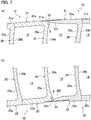
- the turbine nozzle can be configured basically by circularly interlinking one round of vane segments 10 described above. Accordingly, a space (space S illustrated in Fig. 7(a) and Fig. 7(b) ) is produced between the adjacent two vane segments 10.
- a seal member 13 for plugging this space is provided extending between the adjacent vane segments 10.
- the seal member 13 includes a hook seal 30 illustrated in Fig. 5 , and a hanger seal 31, outer seal 32, and inner seal 33 illustrated in an exploded perspective view of Fig. 6 .
- the hook seal 30 is interposed between the outer band section 21 and the hanger 12 of the turbine stator vane 11.
- the hook seal 30 seals a portion between the fore hook 21b and aft hook 21c of the outer band section 21 and the front lock 12b and rear locks 12c of the hanger 12.
- a base 30a of the hook seal 30 includes four sides and a crisscross framework, where a fore side 30b and a rear side 30c are bent corresponding to the groove shape of the front lock 12b and rear lock 12c of the hanger 12, respectively.
- a cutout 30d is formed at two places in the rear side 30c of the hook seal 30. Moreover, corresponding to the cutout 30d, a through-hole (not illustrated) is formed in the upper surface of the rear lock 12c of the hanger 12, and a cutout 21e is formed in the aft hook 21c of the outer band sections 21 of some (in Fig. 5 , the turbine stator vanes 11 of both ends) of the turbine stator vanes 11. In each turbine stator vane 11 and the hook seal 30 of the vane segment 10, movement in the circumferential direction of the turbine shaft with respect to the hanger 12 is restricted by pins (not illustrated) inserted into these cutouts 30d, 21e and into the through-hole (not illustrated) of the hanger 12.
- the space between the fore hook 21b and aft hook 21c of the outer band section 21 and the fore lock 12b and rear lock 12c of the hanger 12, the thickness of the hook seal 30, and the like are set, taking into consideration a difference in the thermal expansion between the turbine stator vane 11 formed of a CMC and the hanger 12 formed of a metallic material, so as to suppress a thermal stress on the turbine stator vane 11 and also prevent the leakage of gas in a high temperature state during operation of a jet engine.
- the hanger seal 31, outer seal 32, and inner seal 33 illustrated in Fig. 6 seal a space between adjacent two vane segments 10.
- the hanger seal 31 is provided in a sealing groove formed in the end surface in the circumferential direction of the hanger 12.
- an auxiliary seal 31a is stacked on a bent portion of the hanger seal 31.
- the outer seal 32 is provided between the base 30a of the hook seal 30 and the outer surface in the radial direction of the outer band section 21, and provided in the sealing groove formed in the end surface in the circumferential direction of the aft hook 21c of the outer band section 21.
- the inner seal 33 is provided in the inner surface in the radial direction of the inner band section 22 and is provided in a groove formed in the end surface in the circumferential direction of the flange 22b of the inner band section 22.
- the outer seal 32 and inner seal 33 extends between the turbine stator vanes 11 of two vane segments 10 which are disposed adjacent to each other with a space therebetween, and are abutted to the outer surface of the base 21a in the outer band section 21 and the outer surface of the base 22a in the inner band section 22 of each turbine stator vane 11, respectively.
- the outer seal 32 and inner seal 33 closely contacts to the outer surface of the base 21a of the outer band section 21 and the outer surface of the base 22a of the inner band section 22 respectively, due to a differential pressure between the inner side (flow path 14) and outer side of the turbine nozzle.
- the leakage of gas from a space between the outer band section 21 side and the inner band section 22 side is prevented.
- the turbine stator vane 11 of the vane segment 10 includes the outer band section 21 and inner band section 22 constituting the flow path 14 which is the gas passage, and has a continuous U-shape as a whole, so that the turbine stator vane 11 can have a simple structure which can be formed using one sheet of fabric, and most of the gas passage can be formed of a CMC.
- effluence of gas from the flow path 14 can be prevented by providing the hook seal 30 in a space between the lock 12b and lock 12c of the hanger 12 and the fore hook 21b and aft hook 21c of the outer band section 21 and by proving the hanger seal 31, outer seal 32, and inner seal 33 illustrated in Fig. 6 between the vane segments 10.
- the bent section sides connecting to the airfoil portion 20 of the outer band section 21 and the inner band section 22 of the turbine stator vane (one of the turbine stator vanes) 11 located on the left side of the space S and the tip sides (i.e., end surfaces 21d and 22d) of the outer band section 21 and the inner band section 22 of the turbine stator vane (other turbine stator vane) 11 located on the right side of the space S are closely disposed without contacting each other.
- a dead space connecting to the flow path 14 which is produced by plugging the space S between the adjacent vane segments 10 with the outer seal 32 or inner seal 33, has a depth corresponding to the thickness of the base 21a or 22a of the outer band section 21 or inner band section 22 of the turbine stator vane 11.
- a tapered surface section (thin-walled part or tapered surface) 21f or 22f is formed in the inner surface facing the flow path 14 in the base 21a or 22a of the outer band section 21 or inner band section 22 of the turbine stator vane 11 located on the right side of the space S.
- This tapered surface section 21f or 22f is formed from a tapered surface which approaches outer surfaces as extending toward the tip (i.e., the end face 21d or 22d) of the base 21a or 22a.
- the thickness of the base 21a or 22a of the outer band section 21 or inner band section 22 can be made thinner, in the end surface 21d or 22d, than the thickness of the bent section side connecting to the airfoil portion 20 so as to reduce the depth of the dead space connecting to the flow path 14, thereby preventing turbulence in the gas passing through the flow path 14 and suppressing a decrease in the turbine efficiency.
- a non-illustrated groove into which a part of the outer seal 32 or inner seals 33 for plugging the space S is inserted, is formed in a portion closer to the inner surface of the outer band section 21 or inner band section 22, so that the depth of the dead space can be reduced even without bringing the outer seal 32 or inner seal 33 closer to the flow path 14.
- the outer seal 32 or inner seal 33 is abutted against the outer surface of the portion where the tapered surface section 21f or 22f is formed in the inner surface of the base 21a or 22a. Therefore, this portion can be reinforced with the outer seal 32 or inner seal 33 even if the thickness of the base 21a or 22a decreases. Accordingly, the portion where the tapered surface section 21f or 22f of the base 21a or 22a is formed will not cause a problem in strength.
- the outer band section 21 or inner band section 22 is formed with a size larger in the blade width direction than that of the airfoil portion 20. Therefore, if the tapered surface section 21f is formed in the base 21a of the outer band section 21 across the entire length in the blade width direction of the airfoil portion 20, then a gap at a position of the inner surface due to the presence or absence of the tapered surface section 21f is produced on the fore hook 21b side or on aft hook 21c side of the outer band section 21.
- a range, in which the tapered surface section 21f or 22f is formed in the inner surface facing the flow path 14 of the base 21a or 22a of the outer band section 21 or inner band section 22, may be limited to a portion indicated by a range W in the view corresponding to the blade width of the airfoil portion 20, as illustrated by an enlarged main portion in the side views of Fig. 8(a) and Fig. 8(b) .
- the tapered surface section 21f or 22f will not be formed in the inner surface of the base 21a or 22a of the outer band section 21 or inner band section 22, so the position of the inner surface of the base 21a or 22a in the outer band section 21 or inner band section 22 is aligned with each other between the turbine stator vanes 11, which are disposed adjacent to each other with a space S therebetween. Accordingly, a decrease in the turbine efficiency due to the turbulence of gas when the gas passes through the flow path 14 can be suppressed.
- the inner seal 33 or outer seal 32 is abutted against the outer surface of the base 21a or 22a of the outer band section 21 or inner band section 22, but a locking groove locked by the end of the outer seal 32 or inner seal 33 may be formed in the outer surface of the base 21a or 22a of the outer band section 21 or inner band section 22.
- a locking piece 21g or 21h is provided in the outer surface of the base 21a of the outer band section 21 of the turbine stator vane 11 located on the both sides of the space S, and a locking piece 22g or 22h is provided also in the outer surface of the base 22a of the inner band section 22 of each turbine stator vane 11.
- both ends of the outer seal 32 or inner seal 33 are inserted into a locking groove 21i or 21j formed from the outer surface of the base 21a of the outer band section 21 and the locking piece 21g or 21h and into a locking piece 22i or 22j formed from the outer surface of the base 22a of the inner band section 22 and the locking piece 22g or 22h.
- the space S between the adjacent vane segments 10 can be appropriately plugged with the outer seal 32 or inner seal 33 by abutting the outer seal 32 or inner seal 33 against the outer surface of the base 21a or 22a of the outer band section 21 or inner band section 22 without depending on a suppress strength of the above-described hook seal 30 or a centrifugal force by the rotation of a turbine nozzle.
- the base 21a or 22a of the outer band section 21 or inner band section 22 constituting the flow path 14 can have a structure having the strength obtained by a CMC.
- a range, in which the tapered surface section 21f or 22f is formed in the inner surface facing the flow path 14 of the base 21a or 22a of the outer band section 21 or inner band section 22, may be limited to a portion indicated by the range W in the view corresponding to the blade width of the airfoil portion 20, as illustrated by an enlarged main portion in the side views of Fig. 10(a) and Fig. 10(b) .
- a seal member attached across the outer surfaces of the band sections of adjacent two turbine stator vanes secures the airtightness of a flow path between the blades of the adjacent two turbine stator vanes, and excellently has the compression efficiency of gas obtained using a turbine nozzle.
- the space between the both band sections plugged with a seal member from the outer surface results in a dead space communicating with the flow path.
- the depth from the flow path of the space plugged with the seal member becomes thinner than the depth when the thin-walled part is not formed, i.e., than the thickness of a portion of the band section where the thin-walled part is not formed.
- the dead space communicated with a flow path produced on the inner side of the seal member can be reduced to suppress a decrease in the compression efficiency of gas passing through the flow path.
- a space between the band sections of two adjacent turbine stator vanes can be appropriately plugged without cutting off the fiber formed of the CMC.
- a seal member for sealing a space between both band sections into a locking groove of each band section, a seal member can be held in a state being abutted against the outer surface of each band section even without separately providing the configuration for pressing a seal member onto a band section from the outer side.
- a thin-walled part will not be formed in the inner surface of the band section to the outer side in the blade width direction from the airfoil portion, so that on the upstream side or downstream side of the flow of gas passing through the flow path, the positions of the inner surfaces of the adjacent two band sections will be aligned with each other.
- a decrease in the compression efficiency of gas passing through the flow path can be suppressed on the upstream side or downstream side of the flow of gas passing through the flow path, while avoiding the generation of a gap at a position in the blade-length direction between the inner surfaces of the adjacent two band sections of the turbine nozzle and thus avoiding the generation of a turbulent flow due to the diffraction of a gas stream or the like.
- the tapered surface section 21f or 22f which approaches the outer surface as extending toward a tip (i.e., toward the end face 21d or 22d) is formed as a thin-walled part.
- the thickness between the outer surface and inner surface of the outer band section 21 or inner band section 22 is, at the tip of the outer band section 21 or inner band section 22, i.e., at the end surface 21d or 22d, thinner than the bent section side connecting to the airfoil portion 20, a structure other than the tapered surface section 21f or 22f, e.g., a depressed portion or the like, may be formed as the thin-walled part.
- the turbine nozzle of a low pressure turbine of a jet engine has been taken as an example and described, but the present disclosure can be applied without being limited to the form and the like as long as a turbine nozzle is the one including a plurality of turbine stator vanes each formed of a CMC.
Landscapes
- Engineering & Computer Science (AREA)
- Mechanical Engineering (AREA)
- General Engineering & Computer Science (AREA)
- Chemical & Material Sciences (AREA)
- Combustion & Propulsion (AREA)
- Turbine Rotor Nozzle Sealing (AREA)
Abstract
Description
- The present disclosure relates to a turbine nozzle of a gas turbine.
- An axial-flow gas turbine includes turbine blades constituted of rotor blades (blades) and turbine nozzles constituted of stator vanes (vanes). The turbine blades and the turbine nozzles are disposed alternately in the axial direction of a rotary shaft. The turbine nozzle is formed from a plurality of stator vane segments (vane segments) circularly disposed, and each vane segment includes a plurality of turbine stator vanes.
- Each vane segment includes a band section which is the base member of an end wall. A seal member is installed between adjacent two vane segments, in other words between adjacent two band sections (see Patent Literature 1). The seal member prevents the main flow of gas from leaking from between adjacent two band sections.
- Patent Literature 1: Japanese Patent Application Laid-Open Publication No.
2009-203947 - A gas turbine is used under high-temperature environments. Therefore, a metal having a high heat-resistance has been conventionally used for a turbine blade and a turbine nozzle. Recently, the use of a ceramic matrix composite (hereinafter, referred to as a "CMC") has been studied. This is because the CMC has a high heat resistance and is lighter than metal. In particular, even when a planar CMC is bent to form a turbine stator vane, a fiber formed of a CMC will not be cut off. Accordingly, a high strength can be assured although the planar CMC is light.
- On the other hand, in a case where a turbine stator vane is formed of a CMC, the strength expected for a turbine stator vane formed of the CMC needs to be maintained by preventing the fiber from being cut off and the continuity from being lost, in plugging a space between band sections with a seal member.
- The present disclosure has been made in view of the above-described circumstances. The purpose of the present disclosure is to provide a turbine nozzle capable of appropriately plugging a space between the band sections of adjacent two turbine stator vanes without cutting off the fiber formed of a CMC when a turbine stator vane of a turbine nozzle in a gas turbine is formed of the CMC.
- An aspect of the present disclosure is a turbine nozzle including: a plurality of turbine stator vanes each being formed by combining ceramics with a fiber fabric, an end of the turbine stator vane being bent and being integrally molded into a shape corresponding to an airfoil portion and to a band section connecting to the airfoil portion; and a flow path of gas between airfoil portions of adjacent two turbine stator vanes; a seal member extending across a bent section connecting to the airfoil portion of the band section of one turbine stator vane of the adjacent two turbine stator vanes, and a tip part of the band section, which is spaced from the bent section of the one turbine stator vane, of the other turbine stator vane of the adjacent two turbine stator vanes; and a thin-walled part formed in an inner surface facing the flow path of the band section of the other turbine stator vane, wherein a thickness between the inner surface of the band section and an outer surface opposite to the inner surface is, at a tip, thinner than the bent section.
- A locking piece of the seal member may be swelled and formed in the outer surfaces of the both band sections, respectively, and the seal member may be abutted against the outer surfaces of the both band sections by inserting the seal member into a locking groove formed from the locking piece of the each band section and the outer surface, respectively.
- The thin-walled part may be formed in a part corresponding to the blade width of the airfoil portion in the inner surface.
- The thin-walled part may be formed from a tapered surface which approaches the outer-surface side as extending toward the tip of the band section.
- The adjacent two turbine stator vanes may be two turbine stator vanes disposed adjacent to each other with the space therebetween among a plurality of turbine stator vanes of each of the two stator vane segments disposed adjacent to each other with the space therebetween, among a plurality of stator vane segments obtained by dividing the turbine nozzle into a plurality of parts.
- According to the present disclosure, when a turbine stator vane of a turbine nozzle in a gas turbine is formed of a CMC, a space between the band sections of adjacent two turbine stator vanes can be appropriately plugged without cutting off the fiber formed of the CMC.
-
-
Fig. 1 is a perspective view of a vane segment constituting a turbine nozzle according to an embodiment of the present disclosure. -
Fig. 2 is a plan view schematically illustrating an expanded state of a fiber fabric used for the turbine stator vane ofFig. 1 . -
Fig. 3 is a perspective view illustrating a state in which the fiber fabric ofFig. 2 is bent and provisionally molded corresponding to the shape of the turbine stator vane. -
Fig. 4 is a perspective view of the turbine stator vane ofFig. 1 formed of a ceramic matrix composite which is formed by combining the temporarily-formed fiber fabric ofFig. 3 with ceramics. -
Fig. 5 is an exploded perspective view of the vane segment ofFig. 1 using the turbine stator vane ofFig. 4 . -
Fig. 6 is an exploded perspective view illustrating the components of a sealing section between the vane segments ofFig. 1 . -
Fig. 7(a) and Fig. 7(b) illustrate an enlarged main portion of the sealing section between the vane segments ofFig. 1 , whereFig. 7 (a) is a cross sectional view of an outer band section andFig. 7(b) is a cross sectional view of an inner band section. -
Fig. 8(a) and Fig. 8(b) illustrate an enlarged main portion of a turbine stator vane having a tapered surface section ofFig. 7(a) and Fig. 7(b) provided in a band section, whereFig. 8 (a) is a front view of the outer band section andFig. 8(b) is a side view of the inner band section. -
Fig. 9(a) and Fig. 9(b) illustrate an enlarged main portion of a sealing section between the vane segments constituting a turbine nozzle according to another embodiment of the present disclosure, whereFig. 9 (a) is a cross sectional view of the outer band section andFig. 9(b) is a cross sectional view of the inner band section. -
Fig. 10 (a) and Fig. 10 (b) illustrate an enlarged main portion of a turbine stator vane having the tapered surface section ofFig. 9 provided in the band section, whereFig. 10(a) is a front view of the outer band section andFig. 10 (b) is a side view of the inner band section. - Hereinafter, the embodiments of the present disclosure will be described with reference to the accompanying drawings.
Fig. 1 is a perspective view of a stator vane segment (vane segment) constituting a turbine nozzle according to an embodiment of the present disclosure. - Note that, in the present embodiment, a case will be taken as an example and described, in which the turbine nozzle is applied to a low pressure turbine constituting a jet engine. Moreover, in the following description, an upstream side of gas along the axial-center direction of the jet engine is referred to as forward and a downstream side of gas is referred to as rearward, the direction around the axial center is referred to as the circumferential direction, the direction perpendicular to the axial center is referred to as the radial direction, the axial-center side in this radial direction is referred to as the inner side, and the opposite side of the axial-center side is referred to as the outer side.
- A
vane segment 10 illustrated inFig. 1 is obtained by dividing a turbine nozzle (stator vane) used for a low pressure turbine of a jet engine into a plurality of parts in the rotation direction (circumferential direction) of a non-illustrated turbine shaft. A plurality ofvane segments 10 are circularly connected, thereby forming a low pressure turbine of a jet engine. - The
vane segment 10 mainly includes a plurality of (in the present embodiment, three)turbine stator vanes 11, a hanger 12 (support member), and a plurality ofseal members 13. Between the adjacent two turbine stator vanes 11, aflow path 14 through which gas passes is formed. - The
turbine stator vane 11 is formed of a ceramic matrix composite (CMC). A fiber (reinforcing fiber) used for the CMC is , for example, a silicon carbide fiber, a carbon fiber, a silicon nitride fiber, an alumina fiber, or a boron nitride fiber. But the fiber may be a fiber formed of other appropriate ceramics, or of a mixture of two or more thereof. - For the
turbine stator vane 11, a three-dimensional fabric is used, which is a fiber three-dimensionally woven in accordance with the thickness required for securing strength. For theturbine stator vane 11, a fabric formed by stacking a plurality of two-dimensional fabrics, or a fabric formed by stacking a plurality of two-dimensional fabrics and sewing together the same with a fiber may be used. The direction of fabrics is selected in consideration of the direction of a stress on theturbine stator vane 11. - The
turbine stator vane 11 is manufactured by provisionally molding a sheet of fabric formed of a fiber, forming ceramics using the steps of impregnation, sintering, or the like, combining the ceramics with the fabric, and thereafter machining this combined one. -
Fig. 2 is a plan view schematically illustrating an expanded state of a fiber fabric used for theturbine stator vane 11 ofFig. 1 . As illustrated inFig. 2 , thefiber fabric 40 is firstly cut into a shape corresponding to an original mold of theturbine stator vane 11. Cutting may be before forming ceramics, or may be thereafter. - That is, the
fiber fabric 40 used for theturbine stator vane 11 is generally cut out so as to include aportion 41 to serve as an airfoil portion, aportion 43 to serve as an outer band section, and aportion 45 to serve as an inner band section. Theportion 43 is to expand in the width direction from one end of theportion 41, while theportion 45 is to expand in the width direction from the other end of thepart 41. However, based on deformation caused by bending the fabric or on a portion to be lost by machining in a subsequent step, an appropriate margin from a minimum required shape (in the view, indicated by a dashed-dotted line) is secured. Not to mention, the fiber is continuous across theentire fiber fabric 40. - As illustrated in a perspective view of
Fig. 3 , thefiber fabric 40 is provisionally molded, by bending, into a shape approximate to theturbine stator vane 11. Bending thefiber fabric 40 may be performed by fitting thefiber fabric 40 into a die and pressing the same, or may be performed using another method. - By bending and provisionally molding the
fiber fabric 40 into a shape approximate to theturbine stator vane 11, theportion 41 to serve as the airfoil portion results in acurve section 51 which is almost straight in the longitudinal direction thereof and gently curved in the width direction thereof. Such acurve section 51 is approximated to the so-called airfoil shape, onesurface 51a thereof being a convexly curved suction surface and anothersurface 51b thereof being a concavely curved pressure surface. - Moreover, the
portion 43 to serve as the outer band section is bent substantially perpendicular to thecurve section 51 to form as an outerbent section 53. The bending direction corresponds to the circumferential direction in the turbine nozzle. Furthermore, at oneend 53a corresponding to a fore side in the axial direction and at anotherend 53b corresponding to a rear side in the axial direction, thecurve section 51 is bent upward, respectively (to the radially outward of the turbine nozzle). The upwardly-bent end 53a is a portion to serve as a fore hook of the outer band section. The upwardly-bent end 53b is a portion to serve as an aft hook of the outer band section. - Similarly, the
portion 45 to serve as the inner band section is bent substantially perpendicular to thecurve section 51 to form as an inner-sidebent section 55. The bending direction corresponds to the circumferential direction in the turbine nozzle. Furthermore, at anend 55a corresponding to the fore side in the axial direction, theportion 45 is bent downward (radially inward of the turbine nozzle). The downwardlybent end 55a is a portion to serve as a flange of the inner band section. - The
fiber fabric 40 provisionally molded as described above is combined with a matrix formed of ceramics. As the method for forming the matrix, a known method can be employed. For example, the matrix can be impregnated into a fiber utilizing a chemical reaction with gas, or solid powder which is a precursor of ceramics may be formed into a slurry, this slurry may be impregnated into a fiber by pouring, and next the resulting fiber may be pyrolytically decomposed or sintered. Through such steps, a matrix formed of ceramics is produced and combined with thefiber fabric 40. - The ceramics combined with the
fiber fabric 40 are machined into theturbine stator vane 11 as described below. - First, the
curve section 51 is machined into anairfoil portion 20 with the so-called airfoil shape which includes asuction surface 20a andpressure surface 20b as illustrated in a perspective view ofFig. 4 . - Moreover, the outer
bent section 53 ofFig. 3 is machined into abase 21a of anouter band section 21 as illustrated inFig. 4 . Both ends 53a and 53b of the outerbent section 53 ofFig. 3 are also machined into afore hook 21b and anaft hook 21c, respectively. - Furthermore, the inner-side
bent section 55 ofFig. 3 is machined into abase 22a of aninner band section 22 as illustrated inFig. 4 . Theend 55a of the inner-sidebent section 55 ofFig. 3 is machined into aflange 22b. - After the above-described machining, a single
turbine stator vane 11 exhibits a substantially U-shape as a whole, as illustrated inFig. 4 . Then, theturbine stator vane 11 will include: the airfoilportion 20 extending in the radial direction in the circumferential direction of a non-illustrated turbine shaft; theouter band section 21 bending from an outer edge in the radial direction of theairfoil portion 20 toward thepressure surface 20b side of theairfoil portion 20 and extending toward a one side in the circumferential direction; and theinner band section 22 bending from an inner end in the radial direction of theairfoil portion 20 toward thepressure surface 20b side of theairfoil portion 20 and extending toward the one side in the circumferential direction. - The above-described
outer band section 21 has a structure, in which thefore hook 21b at a front end extends tilting toward the outer side in the radial direction with respect to thebase 21a forming a gas passage. Moreover, theaft hook 21c at a rear end of theouter band section 21 tilts toward the outer side in the radial direction with respect to thebase 21a, and a tip part thereof projects toward the axial-center direction and an end face thereof is substantially S-shaped. - Moreover, the
inner band section 22 has a structure, in which theflange 22b at a front end extends bending toward the inner side in the radial direction and arear part 22c slightly projects toward the inner side in the radial direction, with respect to thebase 22a forming the gas passage. - The
end face outer band section 21 andinner band section 22 have circular shapes fitted to the shape of thesuction surface 20a of theairfoil portion 20. Thus, as illustrated inFig. 1 , in combining a plurality ofturbine stator vanes 11 as thevane segment 10, theturbine stator vane 11 will closely contact to theouter band section 21 orinner band section 22 in the adjacentturbine stator vane 11 from the bent section side connecting to theairfoil portion 20. Then, brazening is applied to portions where theouter band sections 21 contact each other and theinner band sections 22 contact each other. - The
hanger 12 illustrated inFig. 1 is formed of a metallic material (e.g., a nickel alloy). As illustrated inFig. 5 , thehanger 12 is located on the outer side in the radial direction of thevane segment 10, and fixes thevane segment 10 to a non-illustrated turbine casing. - The
hanger 12 includes abase 12a which covers the outer circumferential surface of thevane segment 10 while being spaced therefrom. Afront lock 12b which locks thefore hook 21b of theouter band section 21 of eachturbine stator vane 11 is formed on a fore side of thebase 12a. Moreover, arear lock 12c which locks theaft hook 21c of theouter band section 21 of eachturbine stator vane 11 is formed on a rear side of thebase 12a. - The
rear lock 12b andfore hook 12c each have a groove shape which is opened toward the center in the axial-center direction on the inner surface side of thehanger 12, and are capable of locking theouter band section 21 to thehanger 12 by sliding, in the circumferential direction, thefore hook 21b of theouter band section 21 to the groove portion of thefront lock 12b, and sliding, in the circumferential direction, theaft hook 21c of theouter band section 21 to the groove portion of therear lock 12c. - Moreover, on the outer-surface side of the
hanger 12, afront rim 12d extending diagonally-forward further from thefront lock 12b and arear rim 12e extended outward in the radial direction from the center portion in the axial-center direction are formed. A plurality of through-holes (not illustrated) are formed in therear rim 12e. - The
hanger 12 configured in this manner is attached to a turbine casing by abutting the tip part of therear rim 12e against an attaching rib (not illustrated) of the turbine casing, superimposing a through-hole (not illustrated) formed in the attaching rib of the turbine casing onto a through-hole (not illustrated) of therear rim 12e, and inserting a fixing pin (not illustrated) extending across both the through-holes into both the through-holes. - On the other hand, regarding the inner side in the radial direction of the
vane segment 10, for example as illustrated inFig. 1 abifurcated cutout 22e formed at a tip of theflange 22b in theinner band section 22 of one (inFig. 1 , the turbine stator vane on the leftmost) of a plurality ofturbine stator vanes 11 is used for fixing thevane segment 10. - That is, the
flange 22b of theinner band section 22 is engaged with an engagement part of a support (not illustrated) on the axial-center side provided in a turbine casing (not illustrated), and then thecutout 22e of theflange 22b is fitted into a pin (not illustrated) extending through the engagement part. Thus, movement of theinner band section 22 in the circumferential direction of thevane segment 10 is restricted, and also movement of theinner band section 22 in the axial-center direction of thevane segment 10 is restricted by the pin (not illustrated) having thecutout 22e fitted thereinto. - The turbine nozzle can be configured basically by circularly interlinking one round of
vane segments 10 described above. Accordingly, a space (space S illustrated inFig. 7(a) and Fig. 7(b) ) is produced between the adjacent twovane segments 10. - Then, in order to prevent the airtightness of the
flow path 14 from being damaged by the space provided between bothvane segments 10, a seal member 13 (seeFig. 1 ) for plugging this space is provided extending between theadjacent vane segments 10. - The
seal member 13 according to the present embodiment includes ahook seal 30 illustrated inFig. 5 , and ahanger seal 31,outer seal 32, andinner seal 33 illustrated in an exploded perspective view ofFig. 6 . - The
hook seal 30 is interposed between theouter band section 21 and thehanger 12 of theturbine stator vane 11. Thehook seal 30 seals a portion between thefore hook 21b andaft hook 21c of theouter band section 21 and thefront lock 12b andrear locks 12c of thehanger 12. - A
base 30a of thehook seal 30 includes four sides and a crisscross framework, where afore side 30b and arear side 30c are bent corresponding to the groove shape of thefront lock 12b andrear lock 12c of thehanger 12, respectively. - A
cutout 30d is formed at two places in therear side 30c of thehook seal 30. Moreover, corresponding to thecutout 30d, a through-hole (not illustrated) is formed in the upper surface of therear lock 12c of thehanger 12, and acutout 21e is formed in theaft hook 21c of theouter band sections 21 of some (inFig. 5 , theturbine stator vanes 11 of both ends) of the turbine stator vanes 11. In eachturbine stator vane 11 and thehook seal 30 of thevane segment 10, movement in the circumferential direction of the turbine shaft with respect to thehanger 12 is restricted by pins (not illustrated) inserted into thesecutouts hanger 12. - Note that, the space between the
fore hook 21b andaft hook 21c of theouter band section 21 and thefore lock 12b andrear lock 12c of thehanger 12, the thickness of thehook seal 30, and the like are set, taking into consideration a difference in the thermal expansion between theturbine stator vane 11 formed of a CMC and thehanger 12 formed of a metallic material, so as to suppress a thermal stress on theturbine stator vane 11 and also prevent the leakage of gas in a high temperature state during operation of a jet engine. - The
hanger seal 31,outer seal 32, andinner seal 33 illustrated inFig. 6 seal a space between adjacent twovane segments 10. Thehanger seal 31 is provided in a sealing groove formed in the end surface in the circumferential direction of thehanger 12. Moreover, anauxiliary seal 31a is stacked on a bent portion of thehanger seal 31. - The
outer seal 32 is provided between the base 30a of thehook seal 30 and the outer surface in the radial direction of theouter band section 21, and provided in the sealing groove formed in the end surface in the circumferential direction of theaft hook 21c of theouter band section 21. Theinner seal 33 is provided in the inner surface in the radial direction of theinner band section 22 and is provided in a groove formed in the end surface in the circumferential direction of theflange 22b of theinner band section 22. - The
outer seal 32 andinner seal 33 extends between theturbine stator vanes 11 of twovane segments 10 which are disposed adjacent to each other with a space therebetween, and are abutted to the outer surface of thebase 21a in theouter band section 21 and the outer surface of thebase 22a in theinner band section 22 of eachturbine stator vane 11, respectively. - Then, the
outer seal 32 andinner seal 33 closely contacts to the outer surface of thebase 21a of theouter band section 21 and the outer surface of thebase 22a of theinner band section 22 respectively, due to a differential pressure between the inner side (flow path 14) and outer side of the turbine nozzle. Thus, the leakage of gas from a space between theouter band section 21 side and theinner band section 22 side is prevented. - In this manner, in the turbine nozzle in the present embodiment, the
turbine stator vane 11 of thevane segment 10 includes theouter band section 21 andinner band section 22 constituting theflow path 14 which is the gas passage, and has a continuous U-shape as a whole, so that theturbine stator vane 11 can have a simple structure which can be formed using one sheet of fabric, and most of the gas passage can be formed of a CMC. - Furthermore, as illustrated in
Fig. 5 , effluence of gas from theflow path 14 can be prevented by providing thehook seal 30 in a space between thelock 12b and lock 12c of thehanger 12 and thefore hook 21b andaft hook 21c of theouter band section 21 and by proving thehanger seal 31,outer seal 32, andinner seal 33 illustrated inFig. 6 between thevane segments 10. - It is not required to form locking grooves in the
base 21a of theouter band section 21 and thebase 22a of theinner band section 22, into which each of thehook seal 30,hanger seal 31,outer seal 32, orinner seal 33 of theseal member 13 is inserted and disposed therein. Therefore, the continuity of the fiber formed of a CMC in thebase base 21a of theouter band section 21 and thebase 22a of theinner band section 22, which constitute theflow path 14, can have a structure having the strength obtained by the CMC. - Incidentally, when the space provided between the
adjacent vane segments 10 is plugged with the above-describedouter seal 32 orinner seal 33, a dead space communicating with theflow path 14 is produced inside theouter seal 32 orinner seal 33. The main-flow gas passing through this dead space cannot obtain a designed speed at a nozzle exit, and causes a reduction in the efficiency of extracting a work (rotational force) at a rear rotor blade. - Then, in the turbine nozzle according to the present embodiment, as illustrated in the cross sectional views of
Fig. 7 (a) and Fig. 7(b) , a new design for reducing the above-described dead space has been applied to theouter band section 21 andinner band section 22 of one of theturbine stator vanes 11 of twovane segments 10 which are disposed adjacent to each other with the space S therebetween. - Here, when the space S is provided between the adjacent two
vane segments 10, the bent section sides connecting to theairfoil portion 20 of theouter band section 21 and theinner band section 22 of the turbine stator vane (one of the turbine stator vanes) 11 located on the left side of the space S and the tip sides (i.e., end surfaces 21d and 22d) of theouter band section 21 and theinner band section 22 of the turbine stator vane (other turbine stator vane) 11 located on the right side of the space S are closely disposed without contacting each other. - Accordingly, a dead space connecting to the
flow path 14 which is produced by plugging the space S between theadjacent vane segments 10 with theouter seal 32 orinner seal 33, has a depth corresponding to the thickness of thebase outer band section 21 orinner band section 22 of theturbine stator vane 11. - Then, in the present embodiment, a tapered surface section (thin-walled part or tapered surface) 21f or 22f is formed in the inner surface facing the
flow path 14 in thebase outer band section 21 orinner band section 22 of theturbine stator vane 11 located on the right side of the space S. Thistapered surface section end face base - Thus, the thickness of the
base outer band section 21 orinner band section 22 can be made thinner, in theend surface airfoil portion 20 so as to reduce the depth of the dead space connecting to theflow path 14, thereby preventing turbulence in the gas passing through theflow path 14 and suppressing a decrease in the turbine efficiency. - Moreover, a non-illustrated groove, into which a part of the
outer seal 32 orinner seals 33 for plugging the space S is inserted, is formed in a portion closer to the inner surface of theouter band section 21 orinner band section 22, so that the depth of the dead space can be reduced even without bringing theouter seal 32 orinner seal 33 closer to theflow path 14. - Therefore, it is possible to prevent a fiber from being cut off due to forming a groove, into which the
outer seal 32 orinner seal 33 is inserted, in theouter band section 21 orinner band section 22, and thus prevent the strength of theouter band section 21 orinner band section 22 from decreasing. - Incidentally, the
outer seal 32 orinner seal 33 is abutted against the outer surface of the portion where the taperedsurface section base outer seal 32 orinner seal 33 even if the thickness of thebase surface section base - Note that, in the
turbine stator vane 11 according to the present embodiment, theouter band section 21 orinner band section 22 is formed with a size larger in the blade width direction than that of theairfoil portion 20. Therefore, if the taperedsurface section 21f is formed in thebase 21a of theouter band section 21 across the entire length in the blade width direction of theairfoil portion 20, then a gap at a position of the inner surface due to the presence or absence of the taperedsurface section 21f is produced on thefore hook 21b side or onaft hook 21c side of theouter band section 21. Even if the taperedsurface section 22f is formed in thebase 22a of theinner band section 22 across the entire length in the blade width direction of theairfoil portion 20, a gap is similarly produced at a position of the inner surface of theinner band section 22 due to the presence or absence of the taperedsurface section 22f. - As described above, on the upstream side or downstream side of the flow of gas passing through the
flow path 14, if a gap at a position in the blade-length direction (radial direction of the turbine shaft) of theairfoil portion 20 is produced in the inner surface of thebase 21a in theouter band section 21 or in the inner surface of thebase 22a in theinner band section 22 between the adjacent twoturbine stator vanes 11, turbulence, such as whirlpool, due to the diffraction of a gas stream will be produced. - Then, a range, in which the tapered
surface section flow path 14 of thebase outer band section 21 orinner band section 22, may be limited to a portion indicated by a range W in the view corresponding to the blade width of theairfoil portion 20, as illustrated by an enlarged main portion in the side views ofFig. 8(a) and Fig. 8(b) . - Thus, on the upstream side or downstream side of the flow of gas passing through the
flow path 14, the taperedsurface section base outer band section 21 orinner band section 22, so the position of the inner surface of thebase outer band section 21 orinner band section 22 is aligned with each other between theturbine stator vanes 11, which are disposed adjacent to each other with a space S therebetween. Accordingly, a decrease in the turbine efficiency due to the turbulence of gas when the gas passes through theflow path 14 can be suppressed. - Moreover, in the embodiment described above, the
inner seal 33 orouter seal 32 is abutted against the outer surface of thebase outer band section 21 orinner band section 22, but a locking groove locked by the end of theouter seal 32 orinner seal 33 may be formed in the outer surface of thebase outer band section 21 orinner band section 22. - Specifically, for example as illustrated in the cross sectional views of
Fig. 9(a) and Fig. 9(b) , alocking piece base 21a of theouter band section 21 of theturbine stator vane 11 located on the both sides of the space S, and alocking piece base 22a of theinner band section 22 of eachturbine stator vane 11. - Then, both ends of the
outer seal 32 orinner seal 33 are inserted into a lockinggroove 21i or 21j formed from the outer surface of thebase 21a of theouter band section 21 and thelocking piece locking piece base 22a of theinner band section 22 and thelocking piece - Thus, the space S between the
adjacent vane segments 10 can be appropriately plugged with theouter seal 32 orinner seal 33 by abutting theouter seal 32 orinner seal 33 against the outer surface of thebase outer band section 21 orinner band section 22 without depending on a suppress strength of the above-describedhook seal 30 or a centrifugal force by the rotation of a turbine nozzle. - Moreover, a place, where the fiber formed of a CMC is cut off by the locking
groove base outer band section 21 orinner band section 22. Therefore, the continuity of the fiber formed of a CMC in thebase locking piece - Accordingly, as with the turbine nozzle of the embodiment previously described, the
base outer band section 21 orinner band section 22 constituting theflow path 14 can have a structure having the strength obtained by a CMC. - Note that, also in the present embodiment, a range, in which the tapered
surface section flow path 14 of thebase outer band section 21 orinner band section 22, may be limited to a portion indicated by the range W in the view corresponding to the blade width of theairfoil portion 20, as illustrated by an enlarged main portion in the side views ofFig. 10(a) and Fig. 10(b) . - According to the present embodiment, a seal member attached across the outer surfaces of the band sections of adjacent two turbine stator vanes secures the airtightness of a flow path between the blades of the adjacent two turbine stator vanes, and excellently has the compression efficiency of gas obtained using a turbine nozzle.
- Here, the space between the both band sections plugged with a seal member from the outer surface results in a dead space communicating with the flow path. However, by forming a thin-walled part in the inner surface of the one band section, the depth from the flow path of the space plugged with the seal member becomes thinner than the depth when the thin-walled part is not formed, i.e., than the thickness of a portion of the band section where the thin-walled part is not formed.
- Accordingly, even without cutting off a fiber formed of a CMC in a portion close to the inner surface in the band sections of the adjacent two turbine stator vanes so as to form a depressed portion and without disposing a seal member for plugging the space between the band sections in a portion close to the inner surface of the band section, the dead space communicated with a flow path produced on the inner side of the seal member can be reduced to suppress a decrease in the compression efficiency of gas passing through the flow path.
- Thus, when a turbine stator vane of a turbine nozzle of a gas turbine is formed of a CMC, a space between the band sections of two adjacent turbine stator vanes can be appropriately plugged without cutting off the fiber formed of the CMC.
- Moreover, by inserting a seal member for sealing a space between both band sections into a locking groove of each band section, a seal member can be held in a state being abutted against the outer surface of each band section even without separately providing the configuration for pressing a seal member onto a band section from the outer side.
- Furthermore, when a band section has a shape larger in the blade width direction than an airfoil portion, a thin-walled part will not be formed in the inner surface of the band section to the outer side in the blade width direction from the airfoil portion, so that on the upstream side or downstream side of the flow of gas passing through the flow path, the positions of the inner surfaces of the adjacent two band sections will be aligned with each other.
- Therefore, a decrease in the compression efficiency of gas passing through the flow path can be suppressed on the upstream side or downstream side of the flow of gas passing through the flow path, while avoiding the generation of a gap at a position in the blade-length direction between the inner surfaces of the adjacent two band sections of the turbine nozzle and thus avoiding the generation of a turbulent flow due to the diffraction of a gas stream or the like.
- This is the end of the description about the turbine nozzle according to the present disclosure, but the present disclosure is not limited to the above-described embodiments.
- For example, in the above-described respective embodiments, in the inner surface facing the
flow path 14 of theouter band section 21 orinner band section 22 of theturbine stator vane 11 located on the right side of the space S, the taperedsurface section end face - However, if the thickness between the outer surface and inner surface of the
outer band section 21 orinner band section 22 is, at the tip of theouter band section 21 orinner band section 22, i.e., at theend surface airfoil portion 20, a structure other than the taperedsurface section - Moreover, in the above-described respective embodiments, a case, where the
vane segments 10 including a plurality ofturbine stator vanes 11 are connected to each other with the space S interposed therebetween, has been taken as an example and described. However, the present disclosure can be widely applicable, regardless of whether or not thevane segment 10 includes a plurality ofturbine stator vanes 11, to the cases where at least some of a plurality ofturbine stator vanes 11 are connected to each other with the space S interposed therebetween. - Furthermore, in the above-described respective embodiments, the turbine nozzle of a low pressure turbine of a jet engine has been taken as an example and described, but the present disclosure can be applied without being limited to the form and the like as long as a turbine nozzle is the one including a plurality of turbine stator vanes each formed of a CMC.
Claims (5)
- A turbine nozzle comprising:a plurality of turbine stator vanes each being formed by combining ceramics with a fiber fabric, an end of the turbine stator vane being bent and being integrally molded into a shape corresponding to an airfoil portion and to a band section connecting to the airfoil portion;a flow path of gas between airfoil portions of adjacent two turbine stator vanes;a seal member extending across a bent section connecting to the airfoil portion of the band section of one turbine stator vane of the adjacent two turbine stator vanes, and a tip part of the band section, which is spaced from the bent section of the one turbine stator vane, of the other turbine stator vane of the adjacent two turbine stator vanes; anda thin-walled part formed in an inner surface facing the flow path of the band section of the other turbine stator vane, wherein a thickness between the inner surface of the band section and an outer surface opposite to the inner surface is, at a tip, thinner than the bent section.
- The turbine nozzle according to claim 1, wherein
a locking piece of the seal member is provided in the outer surfaces of the both band sections, respectively, and wherein the seal member is abutted against the outer surfaces of the both band sections by inserting the seal member into a locking groove formed from the locking piece of the each band section and the outer surface. - The turbine nozzle according to claim 1 or 2, wherein
the thin-walled part is formed in a portion corresponding to a blade width of the airfoil portion in the inner surface. - The turbine nozzle according to any one of claims 1 to 3, wherein
the thin-walled part is formed from a tapered surface which approaches the outer-surface side as extending toward the tip of the band section. - The turbine nozzle according to any one of claims 1 to 4, wherein
the adjacent two turbine stator vanes are two turbine stator vanes disposed adjacent to each other with the space therebetween among a plurality of turbine stator vanes of each of the two stator vane segments disposed adjacent to each other with the space therebetween, among a plurality of stator vane segments obtained by dividing the turbine nozzle into a plurality of parts.
Applications Claiming Priority (2)
| Application Number | Priority Date | Filing Date | Title |
|---|---|---|---|
| JP2016048157A JP6763157B2 (en) | 2016-03-11 | 2016-03-11 | Turbine nozzle |
| PCT/JP2016/080707 WO2017154257A1 (en) | 2016-03-11 | 2016-10-17 | Turbine nozzle |
Publications (3)
| Publication Number | Publication Date |
|---|---|
| EP3428401A1 true EP3428401A1 (en) | 2019-01-16 |
| EP3428401A4 EP3428401A4 (en) | 2019-12-04 |
| EP3428401B1 EP3428401B1 (en) | 2024-05-29 |
Family
ID=59790241
Family Applications (1)
| Application Number | Title | Priority Date | Filing Date |
|---|---|---|---|
| EP16893581.5A Active EP3428401B1 (en) | 2016-03-11 | 2016-10-17 | Turbine nozzle |
Country Status (7)
| Country | Link |
|---|---|
| US (1) | US10815801B2 (en) |
| EP (1) | EP3428401B1 (en) |
| JP (1) | JP6763157B2 (en) |
| CN (1) | CN108779681B (en) |
| CA (1) | CA3016682C (en) |
| RU (1) | RU2708931C1 (en) |
| WO (1) | WO2017154257A1 (en) |
Families Citing this family (12)
| Publication number | Priority date | Publication date | Assignee | Title |
|---|---|---|---|---|
| PL431184A1 (en) * | 2019-09-17 | 2021-03-22 | General Electric Company Polska Spółka Z Ograniczoną Odpowiedzialnością | Turboshaft engine set |
| US11187096B2 (en) | 2019-11-07 | 2021-11-30 | Raytheon Technologies Corporation | Platform seal |
| JP7284737B2 (en) | 2020-08-06 | 2023-05-31 | 三菱重工業株式会社 | gas turbine vane |
| US11603765B1 (en) * | 2021-07-16 | 2023-03-14 | Raytheon Technologies Corporation | Airfoil assembly with fiber-reinforced composite rings and toothed exit slot |
| CN116537889B (en) * | 2022-01-25 | 2025-10-28 | 中国航发商用航空发动机有限责任公司 | Turbine outer ring sealing assembly, turbine outer ring and aircraft engine |
| CN117207639B (en) * | 2022-06-02 | 2025-10-24 | 中国航发商用航空发动机有限责任公司 | Blade laying method and CMC blade manufacturing method |
| US12000306B2 (en) * | 2022-06-03 | 2024-06-04 | Rtx Corporation | Vane arc segment with single-sided platforms |
| US12359574B2 (en) | 2022-06-03 | 2025-07-15 | Rtx Corporation | Vane arc segment with single-sided platform |
| US11952917B2 (en) | 2022-08-05 | 2024-04-09 | Rtx Corporation | Vane multiplet with conjoined singlet vanes |
| US11802487B1 (en) | 2022-08-15 | 2023-10-31 | Rtx Corporation | Gas turbine engine stator vane formed of ceramic matrix composites and having attachment flanges |
| US11866820B1 (en) | 2022-11-21 | 2024-01-09 | Rtx Corporation | Method of processing a CMC airfoil |
| US12078083B2 (en) | 2022-12-20 | 2024-09-03 | Rtx Corporation | Contour weaves for interwoven vanes |
Family Cites Families (23)
| Publication number | Priority date | Publication date | Assignee | Title |
|---|---|---|---|---|
| JPH0612049B2 (en) * | 1989-06-30 | 1994-02-16 | 株式会社東芝 | Turbine nozzle vanes and nozzles |
| CA2031085A1 (en) | 1990-01-16 | 1991-07-17 | Michael P. Hagle | Arrangement for sealing gaps between adjacent circumferential segments of turbine nozzles and shrouds |
| FR2664647B1 (en) * | 1990-07-12 | 1994-08-26 | Europ Propulsion | DISPENSER, PARTICULARLY FOR TURBINE, WITH FIXED BLADES OF THERMOSTRUCTURAL COMPOSITE MATERIAL, AND MANUFACTURING METHOD. |
| JPH09133664A (en) | 1995-11-07 | 1997-05-20 | Toyota Motor Corp | Ultrasonic flaw detection method |
| DE29715180U1 (en) | 1997-08-23 | 1997-10-16 | MTU Motoren- und Turbinen-Union München GmbH, 80995 München | Guide blade for a gas turbine |
| JP3034522B1 (en) | 1999-07-08 | 2000-04-17 | 川崎重工業株式会社 | Gas turbine with improved turbine nozzle |
| JP2002213207A (en) | 2001-01-15 | 2002-07-31 | Mitsubishi Heavy Ind Ltd | Gas turbine segment |
| US6503051B2 (en) * | 2001-06-06 | 2003-01-07 | General Electric Company | Overlapping interference seal and methods for forming the seal |
| JP2005179106A (en) | 2003-12-18 | 2005-07-07 | Honda Motor Co Ltd | High pressure hydrogen production equipment |
| US7140835B2 (en) * | 2004-10-01 | 2006-11-28 | General Electric Company | Corner cooled turbine nozzle |
| US7811054B2 (en) | 2007-05-30 | 2010-10-12 | General Electric Company | Shroud configuration having sloped seal |
| JP5311766B2 (en) | 2007-06-13 | 2013-10-09 | 三菱電機株式会社 | Interface inspection apparatus and interface inspection method |
| JP2009203947A (en) | 2008-02-29 | 2009-09-10 | Hitachi Ltd | Seal device, gas turbine having seal device and operation method of gas turbine |
| GB0814018D0 (en) | 2008-08-01 | 2008-09-10 | Rolls Royce Plc | Vibration damper |
| EP2211023A1 (en) | 2009-01-21 | 2010-07-28 | Siemens Aktiengesellschaft | Guide vane system for a turbomachine with segmented guide vane carrier |
| FR2943942B1 (en) * | 2009-04-06 | 2016-01-29 | Snecma | PROCESS FOR MANUFACTURING A TURBOMACHINE BLADE OF COMPOSITE MATERIAL |
| JP2012078322A (en) | 2010-10-06 | 2012-04-19 | Mitsubishi Heavy Ind Ltd | Ultrasonic test jig |
| JP2012211826A (en) | 2011-03-31 | 2012-11-01 | Aisin Seiki Co Ltd | Ultrasonic inspection device and method |
| FR2978197B1 (en) * | 2011-07-22 | 2015-12-25 | Snecma | TURBINE AND TURBINE TURBINE TURBINE DISPENSER HAVING SUCH A DISPENSER |
| FR2981423B1 (en) | 2011-10-14 | 2013-12-06 | Snecma | ARRANGEMENT OF A CONICAL CONTACT SEAL SEAL IN A TRAPEZOIDAL GRIP |
| US9022728B2 (en) * | 2011-10-28 | 2015-05-05 | United Technologies Corporation | Feather seal slot |
| JP6147482B2 (en) | 2012-10-01 | 2017-06-14 | 高砂熱学工業株式会社 | Charge / discharge system |
| JP6372210B2 (en) * | 2014-07-14 | 2018-08-15 | 株式会社Ihi | Turbine vane made of ceramic matrix composite |
-
2016
- 2016-03-11 JP JP2016048157A patent/JP6763157B2/en active Active
- 2016-10-17 WO PCT/JP2016/080707 patent/WO2017154257A1/en not_active Ceased
- 2016-10-17 RU RU2018135140A patent/RU2708931C1/en active
- 2016-10-17 CN CN201680083273.4A patent/CN108779681B/en not_active Expired - Fee Related
- 2016-10-17 CA CA3016682A patent/CA3016682C/en active Active
- 2016-10-17 EP EP16893581.5A patent/EP3428401B1/en active Active
-
2018
- 2018-09-06 US US16/123,820 patent/US10815801B2/en active Active
Also Published As
| Publication number | Publication date |
|---|---|
| JP2017160885A (en) | 2017-09-14 |
| US20190010815A1 (en) | 2019-01-10 |
| EP3428401A4 (en) | 2019-12-04 |
| CA3016682C (en) | 2020-08-25 |
| JP6763157B2 (en) | 2020-09-30 |
| WO2017154257A1 (en) | 2017-09-14 |
| US10815801B2 (en) | 2020-10-27 |
| CN108779681B (en) | 2021-02-09 |
| RU2708931C1 (en) | 2019-12-12 |
| EP3428401B1 (en) | 2024-05-29 |
| CA3016682A1 (en) | 2017-09-14 |
| CN108779681A (en) | 2018-11-09 |
Similar Documents
| Publication | Publication Date | Title |
|---|---|---|
| EP3428401B1 (en) | Turbine nozzle | |
| EP3124750B1 (en) | Stator vane composed of ceramic-based composite material and corresponding method of producing | |
| CN109424371B (en) | Flowpath assembly for a gas turbine engine and method of assembling the same | |
| US10597334B2 (en) | Turbine comprising turbine stator vanes of a ceramic matrix composite attached to a turbine case | |
| US8961134B2 (en) | Turbine blade or vane with separate endwall | |
| EP1956196B1 (en) | Turbine vane shroud with chamfered rail pocket | |
| EP2213839B1 (en) | Segmented ceramic component for a gas turbine engine | |
| EP3115561B1 (en) | Turbine shroud segment with side perimeter seal | |
| EP3216985B1 (en) | Shield member and jet engine using the same | |
| EP2434096B1 (en) | Gas turbine engine airfoil comprising a conduction pedestal | |
| US11078802B2 (en) | Turbine engine assembly with ceramic matrix composite components and end face seals | |
| JP2017031972A (en) | Near flow path seal for turbomachine | |
| JP2017180190A (en) | Turbine nozzle | |
| US11401834B2 (en) | Method of securing a ceramic matrix composite (CMC) component to a metallic substructure using CMC straps |
Legal Events
| Date | Code | Title | Description |
|---|---|---|---|
| STAA | Information on the status of an ep patent application or granted ep patent |
Free format text: STATUS: THE INTERNATIONAL PUBLICATION HAS BEEN MADE |
|
| PUAI | Public reference made under article 153(3) epc to a published international application that has entered the european phase |
Free format text: ORIGINAL CODE: 0009012 |
|
| STAA | Information on the status of an ep patent application or granted ep patent |
Free format text: STATUS: REQUEST FOR EXAMINATION WAS MADE |
|
| 17P | Request for examination filed |
Effective date: 20181011 |
|
| AK | Designated contracting states |
Kind code of ref document: A1 Designated state(s): AL AT BE BG CH CY CZ DE DK EE ES FI FR GB GR HR HU IE IS IT LI LT LU LV MC MK MT NL NO PL PT RO RS SE SI SK SM TR |
|
| AX | Request for extension of the european patent |
Extension state: BA ME |
|
| DAV | Request for validation of the european patent (deleted) | ||
| DAX | Request for extension of the european patent (deleted) | ||
| A4 | Supplementary search report drawn up and despatched |
Effective date: 20191107 |
|
| RIC1 | Information provided on ipc code assigned before grant |
Ipc: F01D 9/04 20060101ALI20191031BHEP Ipc: F01D 25/24 20060101ALI20191031BHEP Ipc: F01D 9/02 20060101AFI20191031BHEP Ipc: F01D 11/00 20060101ALI20191031BHEP Ipc: F02C 7/28 20060101ALI20191031BHEP |
|
| STAA | Information on the status of an ep patent application or granted ep patent |
Free format text: STATUS: EXAMINATION IS IN PROGRESS |
|
| 17Q | First examination report despatched |
Effective date: 20220704 |
|
| GRAP | Despatch of communication of intention to grant a patent |
Free format text: ORIGINAL CODE: EPIDOSNIGR1 |
|
| STAA | Information on the status of an ep patent application or granted ep patent |
Free format text: STATUS: GRANT OF PATENT IS INTENDED |
|
| INTG | Intention to grant announced |
Effective date: 20240227 |
|
| GRAS | Grant fee paid |
Free format text: ORIGINAL CODE: EPIDOSNIGR3 |
|
| GRAA | (expected) grant |
Free format text: ORIGINAL CODE: 0009210 |
|
| STAA | Information on the status of an ep patent application or granted ep patent |
Free format text: STATUS: THE PATENT HAS BEEN GRANTED |
|
| AK | Designated contracting states |
Kind code of ref document: B1 Designated state(s): AL AT BE BG CH CY CZ DE DK EE ES FI FR GB GR HR HU IE IS IT LI LT LU LV MC MK MT NL NO PL PT RO RS SE SI SK SM TR |
|
| REG | Reference to a national code |
Ref country code: CH Ref legal event code: EP |
|
| REG | Reference to a national code |
Ref country code: IE Ref legal event code: FG4D |
|
| REG | Reference to a national code |
Ref country code: DE Ref legal event code: R096 Ref document number: 602016087780 Country of ref document: DE |
|
| REG | Reference to a national code |
Ref country code: LT Ref legal event code: MG9D |
|
| REG | Reference to a national code |
Ref country code: NL Ref legal event code: MP Effective date: 20240529 |
|
| PG25 | Lapsed in a contracting state [announced via postgrant information from national office to epo] |
Ref country code: IS Free format text: LAPSE BECAUSE OF FAILURE TO SUBMIT A TRANSLATION OF THE DESCRIPTION OR TO PAY THE FEE WITHIN THE PRESCRIBED TIME-LIMIT Effective date: 20240929 |
|
| PG25 | Lapsed in a contracting state [announced via postgrant information from national office to epo] |
Ref country code: BG Free format text: LAPSE BECAUSE OF FAILURE TO SUBMIT A TRANSLATION OF THE DESCRIPTION OR TO PAY THE FEE WITHIN THE PRESCRIBED TIME-LIMIT Effective date: 20240529 |
|
| PG25 | Lapsed in a contracting state [announced via postgrant information from national office to epo] |
Ref country code: HR Free format text: LAPSE BECAUSE OF FAILURE TO SUBMIT A TRANSLATION OF THE DESCRIPTION OR TO PAY THE FEE WITHIN THE PRESCRIBED TIME-LIMIT Effective date: 20240529 Ref country code: FI Free format text: LAPSE BECAUSE OF FAILURE TO SUBMIT A TRANSLATION OF THE DESCRIPTION OR TO PAY THE FEE WITHIN THE PRESCRIBED TIME-LIMIT Effective date: 20240529 |
|
| PG25 | Lapsed in a contracting state [announced via postgrant information from national office to epo] |
Ref country code: GR Free format text: LAPSE BECAUSE OF FAILURE TO SUBMIT A TRANSLATION OF THE DESCRIPTION OR TO PAY THE FEE WITHIN THE PRESCRIBED TIME-LIMIT Effective date: 20240830 |
|
| REG | Reference to a national code |
Ref country code: AT Ref legal event code: MK05 Ref document number: 1690805 Country of ref document: AT Kind code of ref document: T Effective date: 20240529 |
|
| PG25 | Lapsed in a contracting state [announced via postgrant information from national office to epo] |
Ref country code: ES Free format text: LAPSE BECAUSE OF FAILURE TO SUBMIT A TRANSLATION OF THE DESCRIPTION OR TO PAY THE FEE WITHIN THE PRESCRIBED TIME-LIMIT Effective date: 20240529 |
|
| PG25 | Lapsed in a contracting state [announced via postgrant information from national office to epo] |
Ref country code: AT Free format text: LAPSE BECAUSE OF FAILURE TO SUBMIT A TRANSLATION OF THE DESCRIPTION OR TO PAY THE FEE WITHIN THE PRESCRIBED TIME-LIMIT Effective date: 20240529 |
|
| PG25 | Lapsed in a contracting state [announced via postgrant information from national office to epo] |
Ref country code: PL Free format text: LAPSE BECAUSE OF FAILURE TO SUBMIT A TRANSLATION OF THE DESCRIPTION OR TO PAY THE FEE WITHIN THE PRESCRIBED TIME-LIMIT Effective date: 20240529 |
|
| PG25 | Lapsed in a contracting state [announced via postgrant information from national office to epo] |
Ref country code: LV Free format text: LAPSE BECAUSE OF FAILURE TO SUBMIT A TRANSLATION OF THE DESCRIPTION OR TO PAY THE FEE WITHIN THE PRESCRIBED TIME-LIMIT Effective date: 20240529 |
|
| PG25 | Lapsed in a contracting state [announced via postgrant information from national office to epo] |
Ref country code: PL Free format text: LAPSE BECAUSE OF FAILURE TO SUBMIT A TRANSLATION OF THE DESCRIPTION OR TO PAY THE FEE WITHIN THE PRESCRIBED TIME-LIMIT Effective date: 20240529 Ref country code: NO Free format text: LAPSE BECAUSE OF FAILURE TO SUBMIT A TRANSLATION OF THE DESCRIPTION OR TO PAY THE FEE WITHIN THE PRESCRIBED TIME-LIMIT Effective date: 20240829 Ref country code: LV Free format text: LAPSE BECAUSE OF FAILURE TO SUBMIT A TRANSLATION OF THE DESCRIPTION OR TO PAY THE FEE WITHIN THE PRESCRIBED TIME-LIMIT Effective date: 20240529 Ref country code: IS Free format text: LAPSE BECAUSE OF FAILURE TO SUBMIT A TRANSLATION OF THE DESCRIPTION OR TO PAY THE FEE WITHIN THE PRESCRIBED TIME-LIMIT Effective date: 20240929 Ref country code: HR Free format text: LAPSE BECAUSE OF FAILURE TO SUBMIT A TRANSLATION OF THE DESCRIPTION OR TO PAY THE FEE WITHIN THE PRESCRIBED TIME-LIMIT Effective date: 20240529 Ref country code: GR Free format text: LAPSE BECAUSE OF FAILURE TO SUBMIT A TRANSLATION OF THE DESCRIPTION OR TO PAY THE FEE WITHIN THE PRESCRIBED TIME-LIMIT Effective date: 20240830 Ref country code: FI Free format text: LAPSE BECAUSE OF FAILURE TO SUBMIT A TRANSLATION OF THE DESCRIPTION OR TO PAY THE FEE WITHIN THE PRESCRIBED TIME-LIMIT Effective date: 20240529 Ref country code: ES Free format text: LAPSE BECAUSE OF FAILURE TO SUBMIT A TRANSLATION OF THE DESCRIPTION OR TO PAY THE FEE WITHIN THE PRESCRIBED TIME-LIMIT Effective date: 20240529 Ref country code: BG Free format text: LAPSE BECAUSE OF FAILURE TO SUBMIT A TRANSLATION OF THE DESCRIPTION OR TO PAY THE FEE WITHIN THE PRESCRIBED TIME-LIMIT Effective date: 20240529 Ref country code: AT Free format text: LAPSE BECAUSE OF FAILURE TO SUBMIT A TRANSLATION OF THE DESCRIPTION OR TO PAY THE FEE WITHIN THE PRESCRIBED TIME-LIMIT Effective date: 20240529 Ref country code: RS Free format text: LAPSE BECAUSE OF FAILURE TO SUBMIT A TRANSLATION OF THE DESCRIPTION OR TO PAY THE FEE WITHIN THE PRESCRIBED TIME-LIMIT Effective date: 20240829 |
|
| PG25 | Lapsed in a contracting state [announced via postgrant information from national office to epo] |
Ref country code: NL Free format text: LAPSE BECAUSE OF FAILURE TO SUBMIT A TRANSLATION OF THE DESCRIPTION OR TO PAY THE FEE WITHIN THE PRESCRIBED TIME-LIMIT Effective date: 20240529 |
|
| PG25 | Lapsed in a contracting state [announced via postgrant information from national office to epo] |
Ref country code: NL Free format text: LAPSE BECAUSE OF FAILURE TO SUBMIT A TRANSLATION OF THE DESCRIPTION OR TO PAY THE FEE WITHIN THE PRESCRIBED TIME-LIMIT Effective date: 20240529 |
|
| PG25 | Lapsed in a contracting state [announced via postgrant information from national office to epo] |
Ref country code: DK Free format text: LAPSE BECAUSE OF FAILURE TO SUBMIT A TRANSLATION OF THE DESCRIPTION OR TO PAY THE FEE WITHIN THE PRESCRIBED TIME-LIMIT Effective date: 20240529 |
|
| PG25 | Lapsed in a contracting state [announced via postgrant information from national office to epo] |
Ref country code: EE Free format text: LAPSE BECAUSE OF FAILURE TO SUBMIT A TRANSLATION OF THE DESCRIPTION OR TO PAY THE FEE WITHIN THE PRESCRIBED TIME-LIMIT Effective date: 20240529 |
|
| PG25 | Lapsed in a contracting state [announced via postgrant information from national office to epo] |
Ref country code: CZ Free format text: LAPSE BECAUSE OF FAILURE TO SUBMIT A TRANSLATION OF THE DESCRIPTION OR TO PAY THE FEE WITHIN THE PRESCRIBED TIME-LIMIT Effective date: 20240529 |
|
| PG25 | Lapsed in a contracting state [announced via postgrant information from national office to epo] |
Ref country code: SK Free format text: LAPSE BECAUSE OF FAILURE TO SUBMIT A TRANSLATION OF THE DESCRIPTION OR TO PAY THE FEE WITHIN THE PRESCRIBED TIME-LIMIT Effective date: 20240529 Ref country code: RO Free format text: LAPSE BECAUSE OF FAILURE TO SUBMIT A TRANSLATION OF THE DESCRIPTION OR TO PAY THE FEE WITHIN THE PRESCRIBED TIME-LIMIT Effective date: 20240529 |
|
| PG25 | Lapsed in a contracting state [announced via postgrant information from national office to epo] |
Ref country code: SM Free format text: LAPSE BECAUSE OF FAILURE TO SUBMIT A TRANSLATION OF THE DESCRIPTION OR TO PAY THE FEE WITHIN THE PRESCRIBED TIME-LIMIT Effective date: 20240529 |
|
| PG25 | Lapsed in a contracting state [announced via postgrant information from national office to epo] |
Ref country code: SM Free format text: LAPSE BECAUSE OF FAILURE TO SUBMIT A TRANSLATION OF THE DESCRIPTION OR TO PAY THE FEE WITHIN THE PRESCRIBED TIME-LIMIT Effective date: 20240529 Ref country code: SK Free format text: LAPSE BECAUSE OF FAILURE TO SUBMIT A TRANSLATION OF THE DESCRIPTION OR TO PAY THE FEE WITHIN THE PRESCRIBED TIME-LIMIT Effective date: 20240529 Ref country code: RO Free format text: LAPSE BECAUSE OF FAILURE TO SUBMIT A TRANSLATION OF THE DESCRIPTION OR TO PAY THE FEE WITHIN THE PRESCRIBED TIME-LIMIT Effective date: 20240529 Ref country code: EE Free format text: LAPSE BECAUSE OF FAILURE TO SUBMIT A TRANSLATION OF THE DESCRIPTION OR TO PAY THE FEE WITHIN THE PRESCRIBED TIME-LIMIT Effective date: 20240529 Ref country code: DK Free format text: LAPSE BECAUSE OF FAILURE TO SUBMIT A TRANSLATION OF THE DESCRIPTION OR TO PAY THE FEE WITHIN THE PRESCRIBED TIME-LIMIT Effective date: 20240529 Ref country code: CZ Free format text: LAPSE BECAUSE OF FAILURE TO SUBMIT A TRANSLATION OF THE DESCRIPTION OR TO PAY THE FEE WITHIN THE PRESCRIBED TIME-LIMIT Effective date: 20240529 |
|
| PG25 | Lapsed in a contracting state [announced via postgrant information from national office to epo] |
Ref country code: IT Free format text: LAPSE BECAUSE OF FAILURE TO SUBMIT A TRANSLATION OF THE DESCRIPTION OR TO PAY THE FEE WITHIN THE PRESCRIBED TIME-LIMIT Effective date: 20240529 |
|
| REG | Reference to a national code |
Ref country code: DE Ref legal event code: R097 Ref document number: 602016087780 Country of ref document: DE |
|
| PLBE | No opposition filed within time limit |
Free format text: ORIGINAL CODE: 0009261 |
|
| STAA | Information on the status of an ep patent application or granted ep patent |
Free format text: STATUS: NO OPPOSITION FILED WITHIN TIME LIMIT |
|
| PG25 | Lapsed in a contracting state [announced via postgrant information from national office to epo] |
Ref country code: SI Free format text: LAPSE BECAUSE OF FAILURE TO SUBMIT A TRANSLATION OF THE DESCRIPTION OR TO PAY THE FEE WITHIN THE PRESCRIBED TIME-LIMIT Effective date: 20240529 |
|
| REG | Reference to a national code |
Ref country code: DE Ref legal event code: R119 Ref document number: 602016087780 Country of ref document: DE |
|
| 26N | No opposition filed |
Effective date: 20250303 |
|
| REG | Reference to a national code |
Ref country code: CH Ref legal event code: PL |
|
| GBPC | Gb: european patent ceased through non-payment of renewal fee |
Effective date: 20241017 |
|
| PG25 | Lapsed in a contracting state [announced via postgrant information from national office to epo] |
Ref country code: MC Free format text: LAPSE BECAUSE OF FAILURE TO SUBMIT A TRANSLATION OF THE DESCRIPTION OR TO PAY THE FEE WITHIN THE PRESCRIBED TIME-LIMIT Effective date: 20240529 |
|
| PG25 | Lapsed in a contracting state [announced via postgrant information from national office to epo] |
Ref country code: DE Free format text: LAPSE BECAUSE OF NON-PAYMENT OF DUE FEES Effective date: 20250501 |
|
| PG25 | Lapsed in a contracting state [announced via postgrant information from national office to epo] |
Ref country code: GB Free format text: LAPSE BECAUSE OF NON-PAYMENT OF DUE FEES Effective date: 20241017 |
|
| PG25 | Lapsed in a contracting state [announced via postgrant information from national office to epo] |
Ref country code: BE Free format text: LAPSE BECAUSE OF NON-PAYMENT OF DUE FEES Effective date: 20241031 Ref country code: LU Free format text: LAPSE BECAUSE OF NON-PAYMENT OF DUE FEES Effective date: 20241017 |
|
| PG25 | Lapsed in a contracting state [announced via postgrant information from national office to epo] |
Ref country code: CH Free format text: LAPSE BECAUSE OF NON-PAYMENT OF DUE FEES Effective date: 20241031 |
|
| REG | Reference to a national code |
Ref country code: BE Ref legal event code: MM Effective date: 20241031 |
|
| PG25 | Lapsed in a contracting state [announced via postgrant information from national office to epo] |
Ref country code: SE Free format text: LAPSE BECAUSE OF FAILURE TO SUBMIT A TRANSLATION OF THE DESCRIPTION OR TO PAY THE FEE WITHIN THE PRESCRIBED TIME-LIMIT Effective date: 20240529 |
|
| PGFP | Annual fee paid to national office [announced via postgrant information from national office to epo] |
Ref country code: FR Payment date: 20250924 Year of fee payment: 10 |
|
| PG25 | Lapsed in a contracting state [announced via postgrant information from national office to epo] |
Ref country code: IE Free format text: LAPSE BECAUSE OF NON-PAYMENT OF DUE FEES Effective date: 20241017 |
|
| PG25 | Lapsed in a contracting state [announced via postgrant information from national office to epo] |
Ref country code: PT Free format text: LAPSE BECAUSE OF NON-PAYMENT OF DUE FEES Effective date: 20240529 |
|
| PG25 | Lapsed in a contracting state [announced via postgrant information from national office to epo] |
Ref country code: CY Free format text: LAPSE BECAUSE OF FAILURE TO SUBMIT A TRANSLATION OF THE DESCRIPTION OR TO PAY THE FEE WITHIN THE PRESCRIBED TIME-LIMIT; INVALID AB INITIO Effective date: 20161017 |
|
| PG25 | Lapsed in a contracting state [announced via postgrant information from national office to epo] |
Ref country code: HU Free format text: LAPSE BECAUSE OF FAILURE TO SUBMIT A TRANSLATION OF THE DESCRIPTION OR TO PAY THE FEE WITHIN THE PRESCRIBED TIME-LIMIT; INVALID AB INITIO Effective date: 20161017 |