EP3428071A1 - Failsafe electromechanical weight on wheels detection - Google Patents
Failsafe electromechanical weight on wheels detection Download PDFInfo
- Publication number
- EP3428071A1 EP3428071A1 EP18182715.5A EP18182715A EP3428071A1 EP 3428071 A1 EP3428071 A1 EP 3428071A1 EP 18182715 A EP18182715 A EP 18182715A EP 3428071 A1 EP3428071 A1 EP 3428071A1
- Authority
- EP
- European Patent Office
- Prior art keywords
- indicator
- weight
- sensing system
- aircraft
- linkage assembly
- Prior art date
- Legal status (The legal status is an assumption and is not a legal conclusion. Google has not performed a legal analysis and makes no representation as to the accuracy of the status listed.)
- Granted
Links
Images




Classifications
-
- B—PERFORMING OPERATIONS; TRANSPORTING
- B64—AIRCRAFT; AVIATION; COSMONAUTICS
- B64D—EQUIPMENT FOR FITTING IN OR TO AIRCRAFT; FLIGHT SUITS; PARACHUTES; ARRANGEMENT OR MOUNTING OF POWER PLANTS OR PROPULSION TRANSMISSIONS IN AIRCRAFT
- B64D45/00—Aircraft indicators or protectors not otherwise provided for
- B64D45/0005—Devices specially adapted to indicate the position of a movable element of the aircraft, e.g. landing gear
-
- G—PHYSICS
- G01—MEASURING; TESTING
- G01G—WEIGHING
- G01G19/00—Weighing apparatus or methods adapted for special purposes not provided for in the preceding groups
- G01G19/08—Weighing apparatus or methods adapted for special purposes not provided for in the preceding groups for incorporation in vehicles
- G01G19/12—Weighing apparatus or methods adapted for special purposes not provided for in the preceding groups for incorporation in vehicles having electrical weight-sensitive devices
-
- B—PERFORMING OPERATIONS; TRANSPORTING
- B64—AIRCRAFT; AVIATION; COSMONAUTICS
- B64C—AEROPLANES; HELICOPTERS
- B64C25/00—Alighting gear
- B64C25/001—Devices not provided for in the groups B64C25/02 - B64C25/68
-
- B—PERFORMING OPERATIONS; TRANSPORTING
- B64—AIRCRAFT; AVIATION; COSMONAUTICS
- B64D—EQUIPMENT FOR FITTING IN OR TO AIRCRAFT; FLIGHT SUITS; PARACHUTES; ARRANGEMENT OR MOUNTING OF POWER PLANTS OR PROPULSION TRANSMISSIONS IN AIRCRAFT
- B64D45/00—Aircraft indicators or protectors not otherwise provided for
-
- G—PHYSICS
- G01—MEASURING; TESTING
- G01G—WEIGHING
- G01G19/00—Weighing apparatus or methods adapted for special purposes not provided for in the preceding groups
- G01G19/02—Weighing apparatus or methods adapted for special purposes not provided for in the preceding groups for weighing wheeled or rolling bodies, e.g. vehicles
- G01G19/07—Weighing apparatus or methods adapted for special purposes not provided for in the preceding groups for weighing wheeled or rolling bodies, e.g. vehicles for weighing aircraft
-
- B—PERFORMING OPERATIONS; TRANSPORTING
- B64—AIRCRAFT; AVIATION; COSMONAUTICS
- B64C—AEROPLANES; HELICOPTERS
- B64C25/00—Alighting gear
- B64C25/32—Alighting gear characterised by elements which contact the ground or similar surface
- B64C25/34—Alighting gear characterised by elements which contact the ground or similar surface wheeled type, e.g. multi-wheeled bogies
Definitions
- the present disclosure relates to a rotary wing aircraft, and more particularly, to a failsafe mechanism for automatically detecting weight-on-wheels on a landing gear of a rotary wing aircraft.
- WOW weight-on-wheel
- Conventional aircraft may use weight-on-wheel (WOW) sensors and switches to detect a position of a component in a landing gear system that moves when the aircraft lands, such as a shock strut or drag beam, and thus sense a landing in response to such movement.
- Measurement of WOW for fly-by-wire and autonomous rotorcraft can be critical to a correct transition of the rotorcraft control system from airborne state to a ground state.
- Current systems with mechanical switches and sensors do not always actuate at the same amount of force on the landing gear. Further, current systems provide binary analog outputs and lack an integrated self-test capability.
- a weight-on-wheel sensing system includes a movable linkage assembly.
- An indicator is associated with the linkage assembly.
- At least one biasing mechanism is operably coupled to the indicator such that a biasing force of the biasing mechanism is applied to the indicator.
- a position sensing mechanism coupled to the indicator to determine a position of the indicator.
- movement of the linkage assembly causes the indicator to translate about an axis within a normal range of motion.
- the linkage assembly overcomes the biasing force of the at least one biasing mechanism.
- the biasing force of the at least one biasing mechanism causes the indicator to transition to a failure position.
- the position sensing mechanism is operably coupled to a control system to communicate a position of the indicator to the control system.
- control system is configured to determine an operational status of the weight-on-wheel sensing system in response to the position of the indicator.
- the linkage assembly is connected to a landing assembly of an aircraft.
- the linkage assembly includes a push rod.
- the indicator is a free end of the push rod and the position sensing mechanism is one of a linear variable differential transformer, potentiometer, and position sensor, coupled to the free end of the push rod.
- the weight-on-wheel sensing system includes a bracket, wherein the indicator includes a lever mounted to the bracket via a shaft, the lever being rotatable about an axis of rotation.
- the at least one biasing mechanism is connected to a first end of the lever.
- the linkage assembly is connected to a second end of the lever, wherein the linkage assembly is configured to translate along an axis.
- an aircraft includes an airframe, a landing gear operably coupled to the airframe and a weight-on-wheels sensing system associated with the landing gear.
- the weight-on-wheels sensing system includes an indicator movable in response to a position of the at least one landing gear and a position sensing mechanism coupled to the indicator. If the weight-on-wheels sensing system fails, the indicator is automatically biased to a failure position.
- the indicator is movable relative to an axis within a normal range of motion.
- the position sensing mechanism being arranged in communication with the flight control system to communicate a position of at least one of the indicator and the landing gear.
- the position sensing mechanism is operably coupled to a control system to communicate a position of the indicator to the control system.
- the weight-on-wheels sensing system is mounted to at least one of the airframe and the landing gear.
- the weight-on-wheels sensing system is mounted within a stub wing of the aircraft.
- FIG. 1 schematically illustrates a rotary-wing aircraft 10 having a main rotor system 12.
- the aircraft 10 includes an airframe 14 having an extending tail 16 which mounts a tail rotor system 18, such as an anti-torque system, a translational thrust system, a pusher propeller, or a rotor propulsion system for example.
- Power is transferred from one or more engines E to a power transmission gearbox, to drive the main rotor system 12 about a respective axis of rotation A.
- a weight on wheels (WOW) sensing system 20 is provided for use with the aircraft 10, and more particularly, for use with a landing gear of the aircraft 10.
- WOW weight on wheels
- the WOW sensing system 20 includes a mounting bracket 22 positionable in contact with the airframe 14.
- the WOW sensing system 20 is adapted for placement at the same location as conventional WOW systems, such as within the stub wings of the aircraft 10 for example.
- a first surface 24 of the bracket 22 is arranged in direct contact with a corresponding surface 26 of the airframe 14.
- first surface 24 of the bracket 22 and the surface 26 of the airframe 14 have generally complementary contours.
- the surfaces 24, 26 of the bracket 22 and airframe 14 are generally planar.
- other contours are also contemplated herein.
- an opening 30 formed in the bracket 22 is substantially aligned with an opening 32 (see FIGS. 8 and 9 ) formed in the airframe 14.
- a support 36 Protruding from a second surface 34 of the bracket 22, opposite the first surface 24 of the bracket 22, is a support 36.
- the support 36 is vertically aligned with the opening 30.
- the support 36 may be connected to the second surface 34 of the bracket 22, or may be integrally formed therewith.
- the support 36 is generally triangular in shape; however, a support 36 having any shape is within the scope of the disclosure.
- the support 36 may be solid, or alternatively, may have a generally hollow interior to reduce the overall weight of the bracket 22.
- the bracket 22 has a generally angled configuration.
- the support 36 may be connected to both the second surface 34 and an adjacent surface 38 defined by the angle to increase the structural rigidity thereof.
- the bracket 22 is illustrated as having a right angle, other suitable angles are also within the scope.
- a lever or indicator 40 is pivotally coupled to the support extending from the bracket 22.
- the support 36 defines a hollow cavity 42 within which the lever 40 is received.
- the lever 40 may be positioned adjacent either side of the support 36.
- a first shaft 44 extends through a centrally located through hole 46 formed in the lever 40 and an adjacent opening 48 formed in the support 36 to couple the lever 40 to the support 36 to define an axis of rotation R of the lever 40.
- a first end 50 of the lever 40 extends generally beyond an upper surface 52 of the support 36.
- the first end 50 of the lever 40 additionally includes a through hole 54 for receiving a second shaft 56 therein.
- a horizontally oriented pin 58 is arranged at an upper surface 60 of the bracket 22, generally adjacent the second surface 34.
- the second shaft 56 may be coupled to the pin 58 via at least one biasing mechanism 62.
- the second shaft 56 may be coupled to the airframe 14 via at least one biasing mechanism 62.
- a first biasing mechanism 62a is coupled to a first portion of the pin 58 and a portion of the second shaft 56 adjacent a first side 64 of the lever 40 and a second biasing mechanism 62b is coupled to a second portion of the pin 58 and a portion of the second shaft 56 adjacent a second, opposite side 66 of the lever 40.
- the biasing force of the at least one biasing mechanism 62 is configured to bias the lever 40 about the rotational axis R defined by the first shaft in the direction indicated by arrow A (see FIG. 8 ).
- a linkage assembly 70 (best shown in FIGS. 8 and 9 ) associated with the landing gear of the aircraft 10 is operably coupled to the lever 40.
- the linkage assembly 70 includes a drag beam lever arm 72 having a first end 74 configured to connect to the drag beam of the landing gear and a second end 76 coupled to a push rod 78.
- a first end 80 of the push rod 78 may be directly connected to the second end 76, or alternatively, an intermediate link 82 may couple the end 80 of the push rod 78 and the drag beam lever arm 72.
- the push rod 78 extends through the aligned openings 30, 32 formed in the airframe 14 and bracket 22, such that a second end 84 of the push rod 78 is located near the support 36 and lever 40.
- the second end 84 of the push rod 78 is connected to a second end 68 of the lever 40, either directly, or via one or more links.
- the second end 84 of the push rod is offset from the second end of the lever 40, such that a first connector 86 and a second connector 88 extend there between.
- the first connector 86 may include a through hole within which the second end 84 of the push rod 78 is received and a nut 90 may be used to restrict movement of the first connector 86 from the second end 84.
- the first connector 86 is oriented generally perpendicular to the axis defined by the push rod 78
- the second connector 88 is oriented generally parallel to the axis defined by the push rod 78.
- other configurations of a linkage assembly 70 are also contemplated herein.
- connection between the linkage assembly 70 and the second end of the lever 40 drives rotation of the lever 40 about the axis of rotation R, in response to a position of the landing gear.
- the drag beam moves causing the push rod 78 connected thereto to translate relative to the airframe 14 and bracket 22.
- This translation applies a force to the second end 68 of the lever 40, causing the lever 40 to rotate about the axis R. Accordingly, the position of the lever 40 relative to the axis indicates a current state of the landing gear.
- positioning sensing mechanism 90 such as a rotary variable differential transformer (VDT), position sensor, or potentiometer for example, is mounted to the first shaft 44 at a position between the lever 40 and the surface 38 of the bracket 22.
- VDT rotary variable differential transformer
- the system 20 described herein may be adapted for use with a linear positioning sensing mechanism 90.
- the first shaft 44 is operably coupled to the second surface 34 to support the VDT in an optimum position.
- the rotary VDT 90 is operable to sense rotation of the first shaft 44, and therefore the lever 40 about axis R, to determine a status of the landing gear.
- the rotary VDT 90 may communicate with a flight control system of the aircraft to communicate the status of a corresponding landing gear.
- the connection between the linkage assembly 70 and the second end 68 of the lever 40 opposes the biasing force of the biasing mechanism 62 acting on the first end 50 of the lever 40.
- the linkage assembly 70 such as a breakage thereof for example
- the push rod 78 will not apply a force to the lever 40.
- the biasing force of the biasing mechanism 62 causes the lever to rotate in the direction indicated by arrow A, to a position beyond a normal operating range associated with movement of the drag beam.
- the lever 40 will rotate as far about the axis R in the direction of arrow A as possible.
- an alternative WOW sensing system 120 includes a linkage assembly 122 similar to the linkage assembly 70 of the previous embodiments.
- the linkage assembly 122 may include a drag beam lever arm (not shown) having a first end connected to the drag beam of the landing gear and a second end coupled to a push rod 124.
- One or more biasing mechanisms 126 extend from a surface of the airframe 14, or alternatively, from a mounting bracket such as bracket 22 for example, and connect to a free end 128 of the push rod 124.
- the free end 128 of the push rod 124 may include a flange or have a diameter greater than the remainder of the push rod 124 to provide an area for attaching the at least one biasing mechanism 126.
- a position sensing mechanism 130 such as a linear VDT for example, is mounted to the airframe 14 and/or mounting bracket at a position offset from the pushrod 128.
- the VDT is operable to sense translation of the pushrod 124 along an axis to determine a status of the landing gear and may communicate the status of a corresponding landing gear to a flight control system of the aircraft.
- the force applied to the linkage assembly 122 in response to the landing gear opposes the biasing force of the at least one biasing mechanism 126 acting on the free end 128 of the push rod 124.
- the biasing force of the biasing mechanism 126 will cause the push rod 128 to translate about an axis to a position beyond a normal operating range associated with movement of the drag beam.
- the VDT 90, 130 is monitoring the position of a corresponding component, i.e. the first shaft 44 and lever 40 or the push rod 124, the VDT will detect movement of the component to a position indicative of a failure.
- the flight control system will process that the component is in the "failure position" and will determine that the WOW sensing system 20, 120 is not functioning properly and ignore any further output from the sensor system 20, 120.
Landscapes
- Engineering & Computer Science (AREA)
- Aviation & Aerospace Engineering (AREA)
- Physics & Mathematics (AREA)
- General Physics & Mathematics (AREA)
- Mechanical Engineering (AREA)
- Retarders (AREA)
- Tires In General (AREA)
Abstract
Description
- The present disclosure relates to a rotary wing aircraft, and more particularly, to a failsafe mechanism for automatically detecting weight-on-wheels on a landing gear of a rotary wing aircraft.
- Conventional aircraft may use weight-on-wheel (WOW) sensors and switches to detect a position of a component in a landing gear system that moves when the aircraft lands, such as a shock strut or drag beam, and thus sense a landing in response to such movement. Measurement of WOW for fly-by-wire and autonomous rotorcraft can be critical to a correct transition of the rotorcraft control system from airborne state to a ground state. Current systems with mechanical switches and sensors do not always actuate at the same amount of force on the landing gear. Further, current systems provide binary analog outputs and lack an integrated self-test capability.
- According to an embodiment, a weight-on-wheel sensing system includes a movable linkage assembly. An indicator is associated with the linkage assembly. At least one biasing mechanism is operably coupled to the indicator such that a biasing force of the biasing mechanism is applied to the indicator. A position sensing mechanism coupled to the indicator to determine a position of the indicator.
- In addition to one or more of the features described above, or as an alternative, in further embodiments during normal operation, movement of the linkage assembly causes the indicator to translate about an axis within a normal range of motion.
- In addition to one or more of the features described above, or as an alternative, in further embodiments during normal operation, the linkage assembly overcomes the biasing force of the at least one biasing mechanism.
- In addition to one or more of the features described above, or as an alternative, in further embodiments during a failure of the weight-on-wheel sensing system, the biasing force of the at least one biasing mechanism causes the indicator to transition to a failure position.
- In addition to one or more of the features described above, or as an alternative, in further embodiments the position sensing mechanism is operably coupled to a control system to communicate a position of the indicator to the control system.
- In addition to one or more of the features described above, or as an alternative, in further embodiments the control system is configured to determine an operational status of the weight-on-wheel sensing system in response to the position of the indicator.
- In addition to one or more of the features described above, or as an alternative, in further embodiments the linkage assembly is connected to a landing assembly of an aircraft.
- In addition to one or more of the features described above, or as an alternative, in further embodiments the linkage assembly includes a push rod.
- In addition to one or more of the features described above, or as an alternative, in further embodiments the indicator is a free end of the push rod and the position sensing mechanism is one of a linear variable differential transformer, potentiometer, and position sensor, coupled to the free end of the push rod.
- In addition to one or more of the features described above, or as an alternative, in further embodiments the weight-on-wheel sensing system includes a bracket, wherein the indicator includes a lever mounted to the bracket via a shaft, the lever being rotatable about an axis of rotation.
- In addition to one or more of the features described above, or as an alternative, in further embodiments the at least one biasing mechanism is connected to a first end of the lever.
- In addition to one or more of the features described above, or as an alternative, in further embodiments the linkage assembly is connected to a second end of the lever, wherein the linkage assembly is configured to translate along an axis.
- According to another embodiment, an aircraft includes an airframe, a landing gear operably coupled to the airframe and a weight-on-wheels sensing system associated with the landing gear. The weight-on-wheels sensing system includes an indicator movable in response to a position of the at least one landing gear and a position sensing mechanism coupled to the indicator. If the weight-on-wheels sensing system fails, the indicator is automatically biased to a failure position.
- In addition to one or more of the features described above, or as an alternative, in further embodiments during normal operation of the weight-on-wheel sensing system, the indicator is movable relative to an axis within a normal range of motion.
- In addition to one or more of the features described above, or as an alternative, in further embodiments comprising a flight control system, the position sensing mechanism being arranged in communication with the flight control system to communicate a position of at least one of the indicator and the landing gear.
- In addition to one or more of the features described above, or as an alternative, in further embodiments the position sensing mechanism is operably coupled to a control system to communicate a position of the indicator to the control system.
- In addition to one or more of the features described above, or as an alternative, in further embodiments comprising at least one biasing mechanism operably coupled to the indicator and a linkage assembly associated with the indicator.
- In addition to one or more of the features described above, or as an alternative, in further embodiments during normal operation of the weight-on-wheel sensing system, movement of the at least one landing gear overcomes a biasing force of the at least one biasing mechanism acting on the indicator.
- In addition to one or more of the features described above, or as an alternative, in further embodiments the weight-on-wheels sensing system is mounted to at least one of the airframe and the landing gear.
- In addition to one or more of the features described above, or as an alternative, in further embodiments the weight-on-wheels sensing system is mounted within a stub wing of the aircraft.
- The foregoing features and elements may be combined in various combinations without exclusivity, unless expressly indicated otherwise. These features and elements as well as the operation thereof will become more apparent in light of the following description and the accompanying drawings. However, it should be understood that the following description and drawings are intended to be exemplary in nature and non-limiting.
- Various features will become apparent to those skilled in the art from the following detailed description of the disclosed non-limiting embodiments. The drawings that accompany the detailed description can be briefly described as follows:
-
FIG. 1 is a schematic diagram of an example of a rotary wing aircraft; -
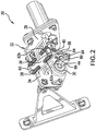
FIG. 2 is an isometric view of a weight-on-wheels sensing system according to an embodiment; -
FIG. 3 is a top view of weight-on-wheels sensing system according to an embodiment; -
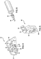
FIG. 4 is an isometric view of a mounting bracket of a weight-on-wheels sensing system according to an embodiment; -
FIG. 5 is an isometric view of a lever of a weight-on-wheels sensing system according to an embodiment; -
FIG. 6 is an isometric view of a rotary variable differential transformer of a weight-on-wheels sensing system according to an embodiment; -
FIG. 7 is an isometric view of a weight-on-wheels sensing system mounted to an airframe according to an embodiment; -
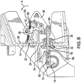
FIG. 8 is a cross-sectional view of a weight-on-wheels sensing system mounted to an airframe during normal operation according to an embodiment; -
FIG. 9 is a cross-sectional view of a weight-on-wheels sensing system mounted to an airframe during a failure according to an embodiment; and -
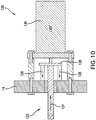
FIG. 10 is a schematic diagram of a weight-on-wheels sensing system according to another embodiment. -
FIG. 1 schematically illustrates a rotary-wing aircraft 10 having a main rotor system 12. Theaircraft 10 includes anairframe 14 having an extending tail 16 which mounts atail rotor system 18, such as an anti-torque system, a translational thrust system, a pusher propeller, or a rotor propulsion system for example. Power is transferred from one or more engines E to a power transmission gearbox, to drive the main rotor system 12 about a respective axis of rotation A. Although a particular rotary wing aircraft configuration is illustrated and described in the disclosed embodiment, other configurations and/or machines, such as a high speed compound rotary wing aircraft with supplemental translational thrust systems, a dual contra-rotating, coaxial rotor system aircraft, and a turbo-prop, tilt-rotor or tilt-wing aircraft for example, will also benefit from the present invention. - With reference now to
FIGS. 2-9 , a weight on wheels (WOW)sensing system 20 is provided for use with theaircraft 10, and more particularly, for use with a landing gear of theaircraft 10. Although a singleWOW sensing system 20 is illustrated, it should be understood that anaircraft 10 may include a plurality ofWOW sensing systems 20, each being associated with a corresponding landing gear. TheWOW sensing system 20 includes amounting bracket 22 positionable in contact with theairframe 14. In an embodiment, theWOW sensing system 20 is adapted for placement at the same location as conventional WOW systems, such as within the stub wings of theaircraft 10 for example. As shown, afirst surface 24 of thebracket 22 is arranged in direct contact with acorresponding surface 26 of theairframe 14. Accordingly thefirst surface 24 of thebracket 22 and thesurface 26 of theairframe 14 have generally complementary contours. In the illustrated, non-limiting embodiment, thesurfaces bracket 22 andairframe 14 are generally planar. However, other contours are also contemplated herein. - When the
bracket 22 is mounted to theairframe 14, such as via a plurality offasteners 28 for example, anopening 30 formed in thebracket 22 is substantially aligned with an opening 32 (seeFIGS. 8 and9 ) formed in theairframe 14. Protruding from asecond surface 34 of thebracket 22, opposite thefirst surface 24 of thebracket 22, is asupport 36. In an embodiment, thesupport 36 is vertically aligned with the opening 30. Thesupport 36 may be connected to thesecond surface 34 of thebracket 22, or may be integrally formed therewith. As shown, thesupport 36 is generally triangular in shape; however, asupport 36 having any shape is within the scope of the disclosure. In addition, thesupport 36 may be solid, or alternatively, may have a generally hollow interior to reduce the overall weight of thebracket 22. In an embodiment, thebracket 22 has a generally angled configuration. In such embodiments, thesupport 36 may be connected to both thesecond surface 34 and anadjacent surface 38 defined by the angle to increase the structural rigidity thereof. Although thebracket 22 is illustrated as having a right angle, other suitable angles are also within the scope. - A lever or
indicator 40 is pivotally coupled to the support extending from thebracket 22. In the illustrated, non-limiting embodiment, thesupport 36 defines ahollow cavity 42 within which thelever 40 is received. However, in other embodiments, thelever 40 may be positioned adjacent either side of thesupport 36. Afirst shaft 44 extends through a centrally located throughhole 46 formed in thelever 40 and anadjacent opening 48 formed in thesupport 36 to couple thelever 40 to thesupport 36 to define an axis of rotation R of thelever 40. - A
first end 50 of thelever 40 extends generally beyond anupper surface 52 of thesupport 36. Thefirst end 50 of thelever 40 additionally includes a throughhole 54 for receiving asecond shaft 56 therein. In an embodiment, a horizontally orientedpin 58 is arranged at anupper surface 60 of thebracket 22, generally adjacent thesecond surface 34. Thesecond shaft 56 may be coupled to thepin 58 via at least one biasing mechanism 62. Alternatively, thesecond shaft 56 may be coupled to theairframe 14 via at least one biasing mechanism 62. In the illustrated, non-limiting embodiment, afirst biasing mechanism 62a is coupled to a first portion of thepin 58 and a portion of thesecond shaft 56 adjacent afirst side 64 of thelever 40 and asecond biasing mechanism 62b is coupled to a second portion of thepin 58 and a portion of thesecond shaft 56 adjacent a second,opposite side 66 of thelever 40. The biasing force of the at least one biasing mechanism 62 is configured to bias thelever 40 about the rotational axis R defined by the first shaft in the direction indicated by arrow A (seeFIG. 8 ). - A linkage assembly 70 (best shown in
FIGS. 8 and9 ) associated with the landing gear of theaircraft 10 is operably coupled to thelever 40. In the illustrated, non-limiting embodiment, thelinkage assembly 70 includes a dragbeam lever arm 72 having afirst end 74 configured to connect to the drag beam of the landing gear and asecond end 76 coupled to apush rod 78. Afirst end 80 of thepush rod 78 may be directly connected to thesecond end 76, or alternatively, anintermediate link 82 may couple theend 80 of thepush rod 78 and the dragbeam lever arm 72. As shown, thepush rod 78 extends through the alignedopenings airframe 14 andbracket 22, such that asecond end 84 of thepush rod 78 is located near thesupport 36 andlever 40. - The
second end 84 of thepush rod 78 is connected to asecond end 68 of thelever 40, either directly, or via one or more links. In the illustrated, non-limiting embodiment, thesecond end 84 of the push rod is offset from the second end of thelever 40, such that afirst connector 86 and asecond connector 88 extend there between. Thefirst connector 86 may include a through hole within which thesecond end 84 of thepush rod 78 is received and anut 90 may be used to restrict movement of thefirst connector 86 from thesecond end 84. As shown, thefirst connector 86 is oriented generally perpendicular to the axis defined by thepush rod 78, and thesecond connector 88 is oriented generally parallel to the axis defined by thepush rod 78. However, other configurations of alinkage assembly 70 are also contemplated herein. - The connection between the
linkage assembly 70 and the second end of thelever 40 drives rotation of thelever 40 about the axis of rotation R, in response to a position of the landing gear. As the landing gear transitions between various configurations, such as a fully extended strut, a partially extended strut, and a fully compressed strut, the drag beam moves causing thepush rod 78 connected thereto to translate relative to theairframe 14 andbracket 22. This translation applies a force to thesecond end 68 of thelever 40, causing thelever 40 to rotate about the axis R. Accordingly, the position of thelever 40 relative to the axis indicates a current state of the landing gear. - In an embodiment,
positioning sensing mechanism 90, such as a rotary variable differential transformer (VDT), position sensor, or potentiometer for example, is mounted to thefirst shaft 44 at a position between thelever 40 and thesurface 38 of thebracket 22. However, it should be understood that in other embodiments, thesystem 20 described herein may be adapted for use with a linearpositioning sensing mechanism 90. In an embodiment, thefirst shaft 44 is operably coupled to thesecond surface 34 to support the VDT in an optimum position. Therotary VDT 90 is operable to sense rotation of thefirst shaft 44, and therefore thelever 40 about axis R, to determine a status of the landing gear. Therotary VDT 90 may communicate with a flight control system of the aircraft to communicate the status of a corresponding landing gear. - During normal operation of the
WOW sensor system 20, the connection between thelinkage assembly 70 and thesecond end 68 of thelever 40 opposes the biasing force of the biasing mechanism 62 acting on thefirst end 50 of thelever 40. In the event of a failure of thelinkage assembly 70, such as a breakage thereof for example, thepush rod 78 will not apply a force to thelever 40. As a result, the biasing force of the biasing mechanism 62 causes the lever to rotate in the direction indicated by arrow A, to a position beyond a normal operating range associated with movement of the drag beam. In an embodiment, in the event of a failure of thelinkage assembly 70, thelever 40 will rotate as far about the axis R in the direction of arrow A as possible. - In another embodiment shown in
FIG. 10 , an alternativeWOW sensing system 120 includes alinkage assembly 122 similar to thelinkage assembly 70 of the previous embodiments. As previously described, thelinkage assembly 122 may include a drag beam lever arm (not shown) having a first end connected to the drag beam of the landing gear and a second end coupled to apush rod 124. One ormore biasing mechanisms 126 extend from a surface of theairframe 14, or alternatively, from a mounting bracket such asbracket 22 for example, and connect to afree end 128 of thepush rod 124. Thefree end 128 of thepush rod 124 may include a flange or have a diameter greater than the remainder of thepush rod 124 to provide an area for attaching the at least onebiasing mechanism 126. In an embodiment, aposition sensing mechanism 130, such as a linear VDT for example, is mounted to theairframe 14 and/or mounting bracket at a position offset from thepushrod 128. The VDT is operable to sense translation of thepushrod 124 along an axis to determine a status of the landing gear and may communicate the status of a corresponding landing gear to a flight control system of the aircraft. - During normal operation of the
WOW sensor system 120, the force applied to thelinkage assembly 122 in response to the landing gear opposes the biasing force of the at least onebiasing mechanism 126 acting on thefree end 128 of thepush rod 124. In the event of a failure of thelinkage assembly 70, such as a breakage thereof for example, the biasing force of thebiasing mechanism 126 will cause thepush rod 128 to translate about an axis to a position beyond a normal operating range associated with movement of the drag beam. - Because the
VDT first shaft 44 andlever 40 or thepush rod 124, the VDT will detect movement of the component to a position indicative of a failure. The flight control system will process that the component is in the "failure position" and will determine that theWOW sensing system sensor system - While the present disclosure is described with reference to exemplary embodiments, it will be understood by those skilled in the art that various changes may be made and equivalents may be substituted without departing from the spirit and scope of the present disclosure. In addition, various modifications may be applied to adapt the teachings of the present disclosure to particular situations, applications, and/or materials, without departing from the essential scope thereof. The present disclosure is thus not limited to the particular examples disclosed herein, but includes all embodiments falling within the scope of the appended claims.
Claims (15)
- A weight-on-wheel sensing system comprising:a movable linkage assembly;
an indicator associated with the linkage assembly;at least one biasing mechanism operably coupled to the indicator such that a biasing force of the biasing mechanism is applied to the indicator; and
a position sensing mechanism coupled to the indicator to determine a position of the indicator. - The weight-on-wheel sensing system of claim 1, wherein during normal operation, movement of the linkage assembly causes the indicator to translate about an axis within a normal range of motion.
- The weight-on-wheel sensing system of claim 1 or 2, wherein during normal operation, the linkage assembly overcomes the biasing force of the at least one biasing mechanism.
- The weight-on-wheel sensing system of one of claims 1 - 3, wherein during a failure of the weight-on-wheel sensing system, the biasing force of the at least one biasing mechanism causes the indicator to transition to a failure position.
- The weight-on-wheel sensing system of one of claims 1 - 4, wherein the position sensing mechanism is operably coupled to a control system to communicate a position of the indicator to the control system, particularly wherein the control system is configured to determine an operational status of the weight-on-wheel sensing system in response to the position of the indicator.
- The weight-on-wheel sensing system of one of claims 1 - 5, wherein the linkage assembly is connected to a landing assembly of an aircraft.
- The weight-on-wheel sensing system of one of claims 1 - 6, wherein the linkage assembly includes a push rod, particularly wherein the indicator is a free end of the push rod and the position sensing mechanism is one of a linear variable differential transformer, potentiometer, and position sensor, coupled to the free end of the push rod.
- The weight-on-wheel sensing system of one of claims 1 - 7, further comprising:a bracket;wherein the indicator includes a lever mounted to the bracket via a shaft, the lever being rotatable about an axis of rotation, particularly wherein the at least one biasing mechanism is connected to a first end of the lever, optionally wherein the linkage assembly is connected to a second end of the lever, wherein the linkage assembly is configured to translate along an axis.
- An aircraft comprising:an airframe;a landing gear operably coupled to the airframe;a weight-on-wheels sensing system associated with the landing gear, the weight-on-wheels sensing system including:an indicator movable in response to a position of the at least one landing gear; anda position sensing mechanism coupled to the indicator, wherein if the weight-on-wheels sensing system fails, the indicator is automatically biased to a failure position.
- The aircraft of claim 9, wherein during normal operation of the weight-on-wheel sensing system, the indicator is movable relative to an axis within a normal range of motion.
- The aircraft of claim 9 or 10, further comprising a flight control system, the position sensing mechanism being arranged in communication with the flight control system to communicate a position of at least one of the indicator and the landing gear.
- The aircraft of one of claims 9 - 11, wherein the position sensing mechanism is operably coupled to a control system to communicate a position of the indicator to the control system.
- The aircraft of one of claims 9 - 12, further comprising:at least one biasing mechanism operably coupled to the indicator; anda linkage assembly associated with the indicator, particularly wherein during normal operation of the weight-on-wheel sensing system, movement of the at least one landing gear overcomes a biasing force of the at least one biasing mechanism acting on the indicator.
- The aircraft of one of claims 9 - 13, wherein the weight-on-wheels sensing system is mounted to at least one of the airframe and the landing gear.
- The aircraft of one of claims 9 - 14, wherein the weight-on-wheels sensing system is mounted within a stub wing of the aircraft.
Applications Claiming Priority (1)
| Application Number | Priority Date | Filing Date | Title |
|---|---|---|---|
| US15/648,078 US10466093B2 (en) | 2017-07-12 | 2017-07-12 | Failsafe electromechanical weight on wheels detection |
Publications (2)
| Publication Number | Publication Date |
|---|---|
| EP3428071A1 true EP3428071A1 (en) | 2019-01-16 |
| EP3428071B1 EP3428071B1 (en) | 2021-03-31 |
Family
ID=62909458
Family Applications (1)
| Application Number | Title | Priority Date | Filing Date |
|---|---|---|---|
| EP18182715.5A Active EP3428071B1 (en) | 2017-07-12 | 2018-07-10 | Failsafe electromechanical weight on wheels detection |
Country Status (2)
| Country | Link |
|---|---|
| US (1) | US10466093B2 (en) |
| EP (1) | EP3428071B1 (en) |
Citations (3)
| Publication number | Priority date | Publication date | Assignee | Title |
|---|---|---|---|---|
| US20080099602A1 (en) * | 2006-09-29 | 2008-05-01 | Zyss Michael J | System and method for detecting ground contact status of an air vehicle |
| US7609056B2 (en) * | 2006-09-11 | 2009-10-27 | Fisher Controls International Llc | Apparatus to determine the position of an actuator |
| EP3100950A1 (en) * | 2015-06-02 | 2016-12-07 | Messier-Dowty Ltd | Aircraft landing gear assembly |
Family Cites Families (14)
| Publication number | Priority date | Publication date | Assignee | Title |
|---|---|---|---|---|
| US2587628A (en) * | 1949-01-24 | 1952-03-04 | Harold B King | Load stroke indicator |
| US3109505A (en) * | 1960-09-09 | 1963-11-05 | D & W Truck Load Indicator Ltd | Load measuring apparatus for vehicles |
| US3167142A (en) * | 1963-08-23 | 1965-01-26 | Pacific Coast Res & Dev Ltd | Self-compensating load indicator apparatus |
| US3488997A (en) * | 1966-08-22 | 1970-01-13 | Pneumo Dynamics Corp | Weight and center of gravity indication system |
| US3480095A (en) * | 1967-11-29 | 1969-11-25 | Railway Express Agency Inc | Axle loading indicator |
| US3499500A (en) * | 1968-02-29 | 1970-03-10 | Boeing Co | Strain-gauge weighing apparatus for vehicle support structure |
| US3517550A (en) * | 1968-05-08 | 1970-06-30 | Us Navy | Load and rate of change of load detection system |
| US3581836A (en) * | 1969-12-02 | 1971-06-01 | Fairchild Camera Instr Co | Method for reducing frictional errors in determining the weight of an object supported by a pneumatic or hydraulic device |
| US3955636A (en) * | 1973-06-01 | 1976-05-11 | Malcolm Anthony Askew | Weighing apparatus for truck and vehicle loads |
| US4312042A (en) * | 1979-12-12 | 1982-01-19 | Sundstrand Data Control, Inc. | Weight, balance, and tire pressure detection systems |
| US4756374A (en) * | 1987-03-31 | 1988-07-12 | Bailey John D | Vehicle load sensing device |
| US6575405B2 (en) | 1999-03-30 | 2003-06-10 | The Boeing Company | Control system and method for a semi-levered landing gear for an aircraft |
| US10732023B2 (en) * | 2016-03-24 | 2020-08-04 | Sikorsky Aircraft Corporation | Measurement system for aircraft, aircraft having the same, and method of measuring weight for aircraft |
| FR3068004B1 (en) * | 2017-06-26 | 2019-07-19 | Airbus Helicopters | LANDING TRAIN WITH AN ON-LINE LOAD MEASURING DEVICE FOR AN AIRCRAFT AND AIRCRAFT |
-
2017
- 2017-07-12 US US15/648,078 patent/US10466093B2/en active Active
-
2018
- 2018-07-10 EP EP18182715.5A patent/EP3428071B1/en active Active
Patent Citations (3)
| Publication number | Priority date | Publication date | Assignee | Title |
|---|---|---|---|---|
| US7609056B2 (en) * | 2006-09-11 | 2009-10-27 | Fisher Controls International Llc | Apparatus to determine the position of an actuator |
| US20080099602A1 (en) * | 2006-09-29 | 2008-05-01 | Zyss Michael J | System and method for detecting ground contact status of an air vehicle |
| EP3100950A1 (en) * | 2015-06-02 | 2016-12-07 | Messier-Dowty Ltd | Aircraft landing gear assembly |
Also Published As
| Publication number | Publication date |
|---|---|
| US20190017862A1 (en) | 2019-01-17 |
| EP3428071B1 (en) | 2021-03-31 |
| US10466093B2 (en) | 2019-11-05 |
Similar Documents
| Publication | Publication Date | Title |
|---|---|---|
| US9169735B2 (en) | Blade-pitch control system with feedback swashplate | |
| US10676182B2 (en) | Tilting coaxial rotor for a rotary wing aircraft | |
| US9476312B2 (en) | Swashplateless active blade pitch control with a mechanical delta-3 restraint having an instantaneous blade pitch-flap coupling response | |
| US20190276144A1 (en) | Redundant helicopter pitch change shaft system | |
| EP3196119B1 (en) | Rotorcraft and associated rotor blade position monitoring system and method | |
| WO2017175195A1 (en) | Rotor for a hover-capable aircraft and method for detecting the attitude of a blade with respect to a hub of such a rotor | |
| US10676184B2 (en) | Pitch control system for an aircraft | |
| US11952111B2 (en) | Electronic control of blade pitch on a tiltrotor | |
| EP1966043B1 (en) | Airfoil for an aircraft and aircraft | |
| US10466093B2 (en) | Failsafe electromechanical weight on wheels detection | |
| EP3653496B1 (en) | Sensor for monitoring rotors | |
| EP4200542B1 (en) | Multiple load path actuator with fault detection | |
| US11015652B2 (en) | Hybrid elastomeric self-lubricated bearing | |
| EP4049931B1 (en) | Downstop load sensing system | |
| EP3842342B1 (en) | Fail-safe tail rotor system | |
| US11964754B2 (en) | Bearing assembly | |
| US11427315B2 (en) | Rotor blade control system | |
| EP2487108B1 (en) | Modular integrated device for rotor blade control | |
| WO2016053410A2 (en) | System for shimming blade fold angle about an axis of rotation | |
| US20240400189A1 (en) | A fixed-wing control mechanism | |
| US11433996B2 (en) | Lightweight low drag rotor pitch beam |
Legal Events
| Date | Code | Title | Description |
|---|---|---|---|
| PUAI | Public reference made under article 153(3) epc to a published international application that has entered the european phase |
Free format text: ORIGINAL CODE: 0009012 |
|
| STAA | Information on the status of an ep patent application or granted ep patent |
Free format text: STATUS: THE APPLICATION HAS BEEN PUBLISHED |
|
| AK | Designated contracting states |
Kind code of ref document: A1 Designated state(s): AL AT BE BG CH CY CZ DE DK EE ES FI FR GB GR HR HU IE IS IT LI LT LU LV MC MK MT NL NO PL PT RO RS SE SI SK SM TR |
|
| AX | Request for extension of the european patent |
Extension state: BA ME |
|
| STAA | Information on the status of an ep patent application or granted ep patent |
Free format text: STATUS: REQUEST FOR EXAMINATION WAS MADE |
|
| 17P | Request for examination filed |
Effective date: 20190716 |
|
| RBV | Designated contracting states (corrected) |
Designated state(s): AL AT BE BG CH CY CZ DE DK EE ES FI FR GB GR HR HU IE IS IT LI LT LU LV MC MK MT NL NO PL PT RO RS SE SI SK SM TR |
|
| GRAP | Despatch of communication of intention to grant a patent |
Free format text: ORIGINAL CODE: EPIDOSNIGR1 |
|
| STAA | Information on the status of an ep patent application or granted ep patent |
Free format text: STATUS: GRANT OF PATENT IS INTENDED |
|
| RIC1 | Information provided on ipc code assigned before grant |
Ipc: G01G 19/07 20060101ALI20201207BHEP Ipc: G01B 7/30 20060101ALI20201207BHEP Ipc: B64D 45/00 20060101AFI20201207BHEP |
|
| INTG | Intention to grant announced |
Effective date: 20201222 |
|
| GRAS | Grant fee paid |
Free format text: ORIGINAL CODE: EPIDOSNIGR3 |
|
| GRAA | (expected) grant |
Free format text: ORIGINAL CODE: 0009210 |
|
| STAA | Information on the status of an ep patent application or granted ep patent |
Free format text: STATUS: THE PATENT HAS BEEN GRANTED |
|
| AK | Designated contracting states |
Kind code of ref document: B1 Designated state(s): AL AT BE BG CH CY CZ DE DK EE ES FI FR GB GR HR HU IE IS IT LI LT LU LV MC MK MT NL NO PL PT RO RS SE SI SK SM TR |
|
| REG | Reference to a national code |
Ref country code: GB Ref legal event code: FG4D Ref country code: CH Ref legal event code: EP |
|
| REG | Reference to a national code |
Ref country code: AT Ref legal event code: REF Ref document number: 1376679 Country of ref document: AT Kind code of ref document: T Effective date: 20210415 |
|
| REG | Reference to a national code |
Ref country code: DE Ref legal event code: R096 Ref document number: 602018014616 Country of ref document: DE |
|
| REG | Reference to a national code |
Ref country code: IE Ref legal event code: FG4D |
|
| REG | Reference to a national code |
Ref country code: LT Ref legal event code: MG9D |
|
| PG25 | Lapsed in a contracting state [announced via postgrant information from national office to epo] |
Ref country code: NO Free format text: LAPSE BECAUSE OF FAILURE TO SUBMIT A TRANSLATION OF THE DESCRIPTION OR TO PAY THE FEE WITHIN THE PRESCRIBED TIME-LIMIT Effective date: 20210630 Ref country code: BG Free format text: LAPSE BECAUSE OF FAILURE TO SUBMIT A TRANSLATION OF THE DESCRIPTION OR TO PAY THE FEE WITHIN THE PRESCRIBED TIME-LIMIT Effective date: 20210630 Ref country code: FI Free format text: LAPSE BECAUSE OF FAILURE TO SUBMIT A TRANSLATION OF THE DESCRIPTION OR TO PAY THE FEE WITHIN THE PRESCRIBED TIME-LIMIT Effective date: 20210331 Ref country code: HR Free format text: LAPSE BECAUSE OF FAILURE TO SUBMIT A TRANSLATION OF THE DESCRIPTION OR TO PAY THE FEE WITHIN THE PRESCRIBED TIME-LIMIT Effective date: 20210331 |
|
| PG25 | Lapsed in a contracting state [announced via postgrant information from national office to epo] |
Ref country code: SE Free format text: LAPSE BECAUSE OF FAILURE TO SUBMIT A TRANSLATION OF THE DESCRIPTION OR TO PAY THE FEE WITHIN THE PRESCRIBED TIME-LIMIT Effective date: 20210331 Ref country code: LV Free format text: LAPSE BECAUSE OF FAILURE TO SUBMIT A TRANSLATION OF THE DESCRIPTION OR TO PAY THE FEE WITHIN THE PRESCRIBED TIME-LIMIT Effective date: 20210331 Ref country code: RS Free format text: LAPSE BECAUSE OF FAILURE TO SUBMIT A TRANSLATION OF THE DESCRIPTION OR TO PAY THE FEE WITHIN THE PRESCRIBED TIME-LIMIT Effective date: 20210331 |
|
| REG | Reference to a national code |
Ref country code: NL Ref legal event code: MP Effective date: 20210331 |
|
| REG | Reference to a national code |
Ref country code: AT Ref legal event code: MK05 Ref document number: 1376679 Country of ref document: AT Kind code of ref document: T Effective date: 20210331 |
|
| PG25 | Lapsed in a contracting state [announced via postgrant information from national office to epo] |
Ref country code: AT Free format text: LAPSE BECAUSE OF FAILURE TO SUBMIT A TRANSLATION OF THE DESCRIPTION OR TO PAY THE FEE WITHIN THE PRESCRIBED TIME-LIMIT Effective date: 20210331 Ref country code: NL Free format text: LAPSE BECAUSE OF FAILURE TO SUBMIT A TRANSLATION OF THE DESCRIPTION OR TO PAY THE FEE WITHIN THE PRESCRIBED TIME-LIMIT Effective date: 20210331 Ref country code: SM Free format text: LAPSE BECAUSE OF FAILURE TO SUBMIT A TRANSLATION OF THE DESCRIPTION OR TO PAY THE FEE WITHIN THE PRESCRIBED TIME-LIMIT Effective date: 20210331 Ref country code: CZ Free format text: LAPSE BECAUSE OF FAILURE TO SUBMIT A TRANSLATION OF THE DESCRIPTION OR TO PAY THE FEE WITHIN THE PRESCRIBED TIME-LIMIT Effective date: 20210331 Ref country code: EE Free format text: LAPSE BECAUSE OF FAILURE TO SUBMIT A TRANSLATION OF THE DESCRIPTION OR TO PAY THE FEE WITHIN THE PRESCRIBED TIME-LIMIT Effective date: 20210331 Ref country code: LT Free format text: LAPSE BECAUSE OF FAILURE TO SUBMIT A TRANSLATION OF THE DESCRIPTION OR TO PAY THE FEE WITHIN THE PRESCRIBED TIME-LIMIT Effective date: 20210331 |
|
| PG25 | Lapsed in a contracting state [announced via postgrant information from national office to epo] |
Ref country code: IS Free format text: LAPSE BECAUSE OF FAILURE TO SUBMIT A TRANSLATION OF THE DESCRIPTION OR TO PAY THE FEE WITHIN THE PRESCRIBED TIME-LIMIT Effective date: 20210731 Ref country code: PL Free format text: LAPSE BECAUSE OF FAILURE TO SUBMIT A TRANSLATION OF THE DESCRIPTION OR TO PAY THE FEE WITHIN THE PRESCRIBED TIME-LIMIT Effective date: 20210331 Ref country code: PT Free format text: LAPSE BECAUSE OF FAILURE TO SUBMIT A TRANSLATION OF THE DESCRIPTION OR TO PAY THE FEE WITHIN THE PRESCRIBED TIME-LIMIT Effective date: 20210802 Ref country code: RO Free format text: LAPSE BECAUSE OF FAILURE TO SUBMIT A TRANSLATION OF THE DESCRIPTION OR TO PAY THE FEE WITHIN THE PRESCRIBED TIME-LIMIT Effective date: 20210331 Ref country code: SK Free format text: LAPSE BECAUSE OF FAILURE TO SUBMIT A TRANSLATION OF THE DESCRIPTION OR TO PAY THE FEE WITHIN THE PRESCRIBED TIME-LIMIT Effective date: 20210331 |
|
| REG | Reference to a national code |
Ref country code: DE Ref legal event code: R097 Ref document number: 602018014616 Country of ref document: DE |
|
| PG25 | Lapsed in a contracting state [announced via postgrant information from national office to epo] |
Ref country code: DK Free format text: LAPSE BECAUSE OF FAILURE TO SUBMIT A TRANSLATION OF THE DESCRIPTION OR TO PAY THE FEE WITHIN THE PRESCRIBED TIME-LIMIT Effective date: 20210331 Ref country code: AL Free format text: LAPSE BECAUSE OF FAILURE TO SUBMIT A TRANSLATION OF THE DESCRIPTION OR TO PAY THE FEE WITHIN THE PRESCRIBED TIME-LIMIT Effective date: 20210331 Ref country code: ES Free format text: LAPSE BECAUSE OF FAILURE TO SUBMIT A TRANSLATION OF THE DESCRIPTION OR TO PAY THE FEE WITHIN THE PRESCRIBED TIME-LIMIT Effective date: 20210331 |
|
| PLBE | No opposition filed within time limit |
Free format text: ORIGINAL CODE: 0009261 |
|
| STAA | Information on the status of an ep patent application or granted ep patent |
Free format text: STATUS: NO OPPOSITION FILED WITHIN TIME LIMIT |
|
| REG | Reference to a national code |
Ref country code: CH Ref legal event code: PL |
|
| 26N | No opposition filed |
Effective date: 20220104 |
|
| PG25 | Lapsed in a contracting state [announced via postgrant information from national office to epo] |
Ref country code: MC Free format text: LAPSE BECAUSE OF FAILURE TO SUBMIT A TRANSLATION OF THE DESCRIPTION OR TO PAY THE FEE WITHIN THE PRESCRIBED TIME-LIMIT Effective date: 20210331 |
|
| REG | Reference to a national code |
Ref country code: BE Ref legal event code: MM Effective date: 20210731 |
|
| PG25 | Lapsed in a contracting state [announced via postgrant information from national office to epo] |
Ref country code: LI Free format text: LAPSE BECAUSE OF NON-PAYMENT OF DUE FEES Effective date: 20210731 Ref country code: CH Free format text: LAPSE BECAUSE OF NON-PAYMENT OF DUE FEES Effective date: 20210731 |
|
| PG25 | Lapsed in a contracting state [announced via postgrant information from national office to epo] |
Ref country code: IS Free format text: LAPSE BECAUSE OF FAILURE TO SUBMIT A TRANSLATION OF THE DESCRIPTION OR TO PAY THE FEE WITHIN THE PRESCRIBED TIME-LIMIT Effective date: 20210731 Ref country code: LU Free format text: LAPSE BECAUSE OF NON-PAYMENT OF DUE FEES Effective date: 20210710 |
|
| PG25 | Lapsed in a contracting state [announced via postgrant information from national office to epo] |
Ref country code: IE Free format text: LAPSE BECAUSE OF NON-PAYMENT OF DUE FEES Effective date: 20210710 Ref country code: BE Free format text: LAPSE BECAUSE OF NON-PAYMENT OF DUE FEES Effective date: 20210731 |
|
| P01 | Opt-out of the competence of the unified patent court (upc) registered |
Effective date: 20230518 |
|
| PG25 | Lapsed in a contracting state [announced via postgrant information from national office to epo] |
Ref country code: CY Free format text: LAPSE BECAUSE OF FAILURE TO SUBMIT A TRANSLATION OF THE DESCRIPTION OR TO PAY THE FEE WITHIN THE PRESCRIBED TIME-LIMIT Effective date: 20210331 |
|
| PG25 | Lapsed in a contracting state [announced via postgrant information from national office to epo] |
Ref country code: HU Free format text: LAPSE BECAUSE OF FAILURE TO SUBMIT A TRANSLATION OF THE DESCRIPTION OR TO PAY THE FEE WITHIN THE PRESCRIBED TIME-LIMIT; INVALID AB INITIO Effective date: 20180710 Ref country code: GR Free format text: LAPSE BECAUSE OF FAILURE TO SUBMIT A TRANSLATION OF THE DESCRIPTION OR TO PAY THE FEE WITHIN THE PRESCRIBED TIME-LIMIT Effective date: 20210331 |
|
| PG25 | Lapsed in a contracting state [announced via postgrant information from national office to epo] |
Ref country code: MK Free format text: LAPSE BECAUSE OF FAILURE TO SUBMIT A TRANSLATION OF THE DESCRIPTION OR TO PAY THE FEE WITHIN THE PRESCRIBED TIME-LIMIT Effective date: 20210331 |
|
| PG25 | Lapsed in a contracting state [announced via postgrant information from national office to epo] |
Ref country code: MT Free format text: LAPSE BECAUSE OF FAILURE TO SUBMIT A TRANSLATION OF THE DESCRIPTION OR TO PAY THE FEE WITHIN THE PRESCRIBED TIME-LIMIT Effective date: 20210331 |
|
| PGFP | Annual fee paid to national office [announced via postgrant information from national office to epo] |
Ref country code: DE Payment date: 20250729 Year of fee payment: 8 |
|
| PGFP | Annual fee paid to national office [announced via postgrant information from national office to epo] |
Ref country code: IT Payment date: 20250721 Year of fee payment: 8 |
|
| PGFP | Annual fee paid to national office [announced via postgrant information from national office to epo] |
Ref country code: GB Payment date: 20250728 Year of fee payment: 8 |
|
| PGFP | Annual fee paid to national office [announced via postgrant information from national office to epo] |
Ref country code: FR Payment date: 20250725 Year of fee payment: 8 |
|
| PG25 | Lapsed in a contracting state [announced via postgrant information from national office to epo] |
Ref country code: TR Free format text: LAPSE BECAUSE OF FAILURE TO SUBMIT A TRANSLATION OF THE DESCRIPTION OR TO PAY THE FEE WITHIN THE PRESCRIBED TIME-LIMIT Effective date: 20210331 |