EP3428069A1 - Cabin air compressor motor cooling flow enhancement cowl - Google Patents
Cabin air compressor motor cooling flow enhancement cowl Download PDFInfo
- Publication number
- EP3428069A1 EP3428069A1 EP18182893.0A EP18182893A EP3428069A1 EP 3428069 A1 EP3428069 A1 EP 3428069A1 EP 18182893 A EP18182893 A EP 18182893A EP 3428069 A1 EP3428069 A1 EP 3428069A1
- Authority
- EP
- European Patent Office
- Prior art keywords
- motor cooling
- cac
- cac motor
- cowl
- cooling duct
- Prior art date
- Legal status (The legal status is an assumption and is not a legal conclusion. Google has not performed a legal analysis and makes no representation as to the accuracy of the status listed.)
- Granted
Links
Images




Classifications
-
- B—PERFORMING OPERATIONS; TRANSPORTING
- B64—AIRCRAFT; AVIATION; COSMONAUTICS
- B64D—EQUIPMENT FOR FITTING IN OR TO AIRCRAFT; FLIGHT SUITS; PARACHUTES; ARRANGEMENT OR MOUNTING OF POWER PLANTS OR PROPULSION TRANSMISSIONS IN AIRCRAFT
- B64D13/00—Arrangements or adaptations of air-treatment apparatus for aircraft crew or passengers, or freight space
- B64D13/06—Arrangements or adaptations of air-treatment apparatus for aircraft crew or passengers, or freight space the air being conditioned
- B64D13/08—Arrangements or adaptations of air-treatment apparatus for aircraft crew or passengers, or freight space the air being conditioned the air being heated or cooled
-
- B—PERFORMING OPERATIONS; TRANSPORTING
- B64—AIRCRAFT; AVIATION; COSMONAUTICS
- B64D—EQUIPMENT FOR FITTING IN OR TO AIRCRAFT; FLIGHT SUITS; PARACHUTES; ARRANGEMENT OR MOUNTING OF POWER PLANTS OR PROPULSION TRANSMISSIONS IN AIRCRAFT
- B64D13/00—Arrangements or adaptations of air-treatment apparatus for aircraft crew or passengers, or freight space
- B64D13/06—Arrangements or adaptations of air-treatment apparatus for aircraft crew or passengers, or freight space the air being conditioned
-
- B—PERFORMING OPERATIONS; TRANSPORTING
- B64—AIRCRAFT; AVIATION; COSMONAUTICS
- B64D—EQUIPMENT FOR FITTING IN OR TO AIRCRAFT; FLIGHT SUITS; PARACHUTES; ARRANGEMENT OR MOUNTING OF POWER PLANTS OR PROPULSION TRANSMISSIONS IN AIRCRAFT
- B64D13/00—Arrangements or adaptations of air-treatment apparatus for aircraft crew or passengers, or freight space
- B64D13/02—Arrangements or adaptations of air-treatment apparatus for aircraft crew or passengers, or freight space the air being pressurised
-
- B—PERFORMING OPERATIONS; TRANSPORTING
- B64—AIRCRAFT; AVIATION; COSMONAUTICS
- B64D—EQUIPMENT FOR FITTING IN OR TO AIRCRAFT; FLIGHT SUITS; PARACHUTES; ARRANGEMENT OR MOUNTING OF POWER PLANTS OR PROPULSION TRANSMISSIONS IN AIRCRAFT
- B64D13/00—Arrangements or adaptations of air-treatment apparatus for aircraft crew or passengers, or freight space
- B64D13/06—Arrangements or adaptations of air-treatment apparatus for aircraft crew or passengers, or freight space the air being conditioned
- B64D2013/0603—Environmental Control Systems
- B64D2013/0618—Environmental Control Systems with arrangements for reducing or managing bleed air, using another air source, e.g. ram air
-
- B—PERFORMING OPERATIONS; TRANSPORTING
- B64—AIRCRAFT; AVIATION; COSMONAUTICS
- B64D—EQUIPMENT FOR FITTING IN OR TO AIRCRAFT; FLIGHT SUITS; PARACHUTES; ARRANGEMENT OR MOUNTING OF POWER PLANTS OR PROPULSION TRANSMISSIONS IN AIRCRAFT
- B64D13/00—Arrangements or adaptations of air-treatment apparatus for aircraft crew or passengers, or freight space
- B64D13/06—Arrangements or adaptations of air-treatment apparatus for aircraft crew or passengers, or freight space the air being conditioned
- B64D2013/0603—Environmental Control Systems
- B64D2013/0644—Environmental Control Systems including electric motors or generators
-
- B—PERFORMING OPERATIONS; TRANSPORTING
- B64—AIRCRAFT; AVIATION; COSMONAUTICS
- B64D—EQUIPMENT FOR FITTING IN OR TO AIRCRAFT; FLIGHT SUITS; PARACHUTES; ARRANGEMENT OR MOUNTING OF POWER PLANTS OR PROPULSION TRANSMISSIONS IN AIRCRAFT
- B64D33/00—Arrangement in aircraft of power plant parts or auxiliaries not otherwise provided for
- B64D33/02—Arrangement in aircraft of power plant parts or auxiliaries not otherwise provided for of combustion air intakes
- B64D2033/024—Arrangement in aircraft of power plant parts or auxiliaries not otherwise provided for of combustion air intakes comprising cooling means
-
- Y—GENERAL TAGGING OF NEW TECHNOLOGICAL DEVELOPMENTS; GENERAL TAGGING OF CROSS-SECTIONAL TECHNOLOGIES SPANNING OVER SEVERAL SECTIONS OF THE IPC; TECHNICAL SUBJECTS COVERED BY FORMER USPC CROSS-REFERENCE ART COLLECTIONS [XRACs] AND DIGESTS
- Y02—TECHNOLOGIES OR APPLICATIONS FOR MITIGATION OR ADAPTATION AGAINST CLIMATE CHANGE
- Y02T—CLIMATE CHANGE MITIGATION TECHNOLOGIES RELATED TO TRANSPORTATION
- Y02T50/00—Aeronautics or air transport
- Y02T50/50—On board measures aiming to increase energy efficiency
Definitions
- This disclosure relates to aircraft environmental control systems, and more particularly, a cabin air compressor motor cooling flow enhancement cowl for a ram air outlet header of an aircraft environmental control system.
- ram air flow may be utilized to remove heat from various aircraft lubrication and electrical systems and/or used to condition aircraft cabin air.
- a fan is typically utilized to increase air flow to the cooling systems. Cooling flow is drawn at a ram air inlet through a ram inlet header and heat exchangers to a ram air outlet header, the fan, and a ram air outlet.
- the cooling flow can also directly supply cooling air for various components, such as fan and compressor bearings.
- a ram air system can receive discharge air from heated components such as motor windings. Pressure differentials between components of a ram air system can limit the effectiveness of cooling flows supported by the ram air system
- a cabin air compressor (CAC) motor cooling flow enhancement cowl includes a cowl body and a coupling interface.
- the cowl body is contoured to extend from a CAC motor cooling duct discharge of a ram air outlet header.
- the cowl body includes a backward facing step to form an air dam in a ram air flow path to divert ram system air away from the CAC motor cooling duct discharge.
- the coupling interface is formed at an upstream end of the cowl body to engage with a transition edge of the CAC motor cooling duct discharge.
- cowl body forms a CAC motor cooling duct extension channel with respect to a bell mouth of the ram air outlet header upstream from a ram air fan inlet interface of the ram air outlet header.
- further embodiments may include where the CAC motor cooling duct extension channel is sized to partially extend into the bell mouth when the coupling interface is engaged with the transition edge of the CAC motor cooling duct discharge.
- further embodiments may include where the CAC motor cooling duct extension channel is sized to extend in the bell mouth beyond the ram air fan inlet interface when the coupling interface is engaged with the transition edge of the CAC motor cooling duct discharge.
- further embodiments may include where a channel height of the CAC motor cooling duct extension channel is less than a channel height at the CAC motor cooling duct discharge.
- further embodiments may include where a channel height of the CAC motor cooling duct extension channel is greater than a channel height at the CAC motor cooling duct discharge.
- further embodiments may include where the coupling interface is contoured to at least partially wrap around an interior surface of a CAC motor cooling duct of the ram air outlet header and an interior surface of the bell mouth.
- a ram air outlet header includes a header body and a CAC motor cooling flow enhancement cowl.
- the header body includes a CAC motor cooling duct that intersects a ram air fan flow path at a CAC motor cooling duct discharge in a bell mouth upstream from a ram air fan inlet interface.
- the CAC motor cooling flow enhancement cowl includes a cowl body that extends from the CAC motor cooling duct discharge with a backward facing step that forms an air dam in the ram air flow path to divert ram system air away from CAC motor cooling duct discharge.
- a method of installing a CAC motor cooling flow enhancement cowl in a ram air outlet header includes positioning a cowl body comprising a backward facing step of the CAC motor cooling flow enhancement cowl to form an air dam in a ram air flow path of the ram air outlet header to divert ram system air away from a CAC motor cooling duct discharge in a bell mouth upstream from a ram air fan inlet interface of the ram air outlet header.
- a coupling interface of the CAC motor cooling flow enhancement cowl is fastened to a transition edge of the CAC motor cooling duct discharge.
- a technical effect of embodiments is achieved by a CAC motor cooling flow enhancement cowl that forms an air dam in a ram air flow path to divert ram system air away from a CAC motor cooling duct discharge of a ram air outlet header as described herein.
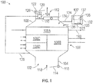
- FIG. 1 shown in FIG. 1 is a schematic view of a ram air cooling system 100 for an aircraft environmental control system (ECS).
- the ram air cooling system 100 includes a ram air inlet 102, a ram inlet header 104, a heat exchanger assembly 106, a ram air outlet header 108, a ram air fan 110, and a ram air outlet 112.
- a ram air inlet door 114 controlled by a ram air inlet door actuator 116 allows ram air 118 to enter the ram inlet header 104, pass through the heat exchanger assembly 106 to the ram air outlet header 108 and exits through the ram air outlet 112.
- a ram air outlet door 120 is controlled by a ram air outlet door actuator 122 at the ram air outlet 112.
- the ram air fan 110 can be used to increase a flow rate of the ram air 118 through the ram air cooling system 100.
- the ram air 118 may be bypassed around the ram air fan 110 through a ram air fan housing 138 as depicted in FIG. 2 .
- An electric motor 124 drives the ram air fan 110 and may be controlled using a speed sensor 126.
- the electric motor 124 can receive a ram fan bearing cooling flow 128 drawn from the ram inlet header 104.
- the ram air cooling system 100 may also include a check valve 130 to control for over-pressure conditions.
- the heat exchanger assembly 106 includes a primary heat exchanger 106A, a secondary heat exchanger 106B, a tertiary heat exchanger 106C, and a quaternary heat exchanger 106D.
- a cooled flow 148 from the primary heat exchanger 106A may be used to cool various heat loads.
- a water collector overflow drain 136 is also routed to the ram air outlet header 108.
- a cabin air compressor (CAC) 132 draws in air from the atmosphere through a compressor impeller 133 at a CAC compressor inlet 131 and provides a CAC motor cooling return 134 to the ram air outlet header 108.
- the compressor impeller 133 can be driven by a CAC motor 135.
- a pressure differential between the CAC compressor inlet 131 and the CAC motor cooling return 134 drives a cooling flow to motor windings 137 of the CAC motor 135.
- a higher pressure differential increases a cooling mass flow rate through the CAC motor 135.
- effectiveness of the cooling can impact the reliability of the CAC motor 135, particularly in high temperature environments.
- the pressure at the CAC compressor inlet 131 is uncontrolled in the ram air cooling system 100 and is a function of atmospheric pressure.
- embodiments reduce the discharge pressure of the CAC motor cooling return 134.
- FIG. 2 is a perspective view of an embodiment of the ram air cooling system 100 of FIG. 1 .
- the heat exchanger assembly 106 is coupled to the ram inlet header 104 and the ram air outlet header 108.
- the ram air outlet header 108 receives heated ram air that passes through the heat exchanger assembly 106.
- the ram air outlet header 108 also receives a heated bearing cooling supply return from the CAC motor cooling return 134.
- the ram air outlet header 108 can also receive water at the water collector overflow drain 136.
- a ram air fan housing 138 is coupled to the ram air outlet header 108 via a clamp 144 and can receive a combination of heated ram air, heated bearing cooling supply return air, and water.
- the ram air fan housing 138 contains the ram air fan 110, electric motor 124, and speed sensor 126 of FIG. 1 .
- the ram air outlet header 108 also includes a mounting bracket 140 for a pack control unit 142.
- the pack control unit 142 may include electronics to control electric components of the ram air cooling system 100, such as the ram air inlet door actuator 116, the ram air outlet door actuator 122, and/or the electric motor 124 of FIG. 1 .
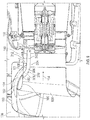
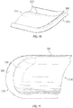
- FIG. 3 depicts a cross section of the ram air outlet header 108 of FIGS. 1 and 2 having a header body 150 with a CAC motor cooling flow enhancement cowl 202 coupled thereto. Further details of the CAC motor cooling flow enhancement cowl 202 are described with respect to FIGS. 4 , 5 , 6 , 7, and 8 .
- the header body 150 includes a CAC motor cooling duct 152 that intersects a ram air fan flow path 154 at a CAC motor cooling duct discharge 156 in a bell mouth 158 upstream from a ram air fan inlet interface 160.
- the CAC motor cooling flow enhancement cowl 202 includes a cowl body 204 that extends from the CAC motor cooling duct discharge 156 with a backward facing step 206 that forms an air dam in the ram air flow path 154 to divert ram system air away from CAC motor cooling duct discharge 156.
- a coupling interface 208 is formed at an upstream end 210 of the cowl body 204 to engage with a transition edge 162 of the CAC motor cooling duct discharge 156.
- the coupling interface 208 can be contoured to at least partially wrap around an interior surface 164 of the CAC motor cooling duct 152 and an interior surface 166 of the bell mouth 158.
- the cowl body 204 forms a CAC motor cooling duct extension channel 212 with respect to the bell mouth 158.
- the CAC motor cooling duct extension channel 212 can be sized to partially extend into the bell mouth 158 when the coupling interface 208 is engaged with the transition edge 162 of the CAC motor cooling duct discharge 156.
- a channel height H2 of the CAC motor cooling duct extension channel 212 is less than a channel height H1 at the CAC motor cooling duct discharge 156.
- the channel height H2 of the CAC motor cooling duct extension channel 212 can be greater than or equal to the channel height H1 at the CAC motor cooling duct discharge 156.
- the CAC motor cooling return 134 of FIG. 1 is routed through the CAC motor cooling duct 152 and the CAC motor cooling duct extension channel 212 to merge with the ram air fan flow path 154 at a downstream end 214 of the CAC motor cooling flow enhancement cowl 202.
- the backward facing step 206 creates a lower pressure zone in the ram air fan flow path 154 allowing the CAC motor cooling return 134 to discharge into the ram air fan flow path 154 at a lower static pressure.
- the reduced static pressure can increase a pressure differential with respect to the CAC motor 135 of FIG. 1 to drive an increased cooling flow through the CAC motor 135, which reduces the temperature of the CAC motor 135 to increase motor reliability.
- a number of sizing variations of the CAC motor cooling flow enhancement cowl 202 are contemplated as depicted in the examples of FIGS. 9-20 .
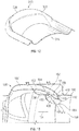
- CAC motor cooling flow enhancement cowl 302 has a cowl body 304 that forms a CAC motor cooling duct extension channel 312 with respect to the bell mouth 158.
- the CAC motor cooling duct extension channel 312 is sized to extend in the bell mouth 158 beyond the ram air fan inlet interface 160 when coupling interface 308 is engaged with the transition edge 162 of the CAC motor cooling duct discharge 156.
- the backward facing step 306 can be substantially similar to the backward facing step 206 of FIG. 4 . Also, similar to CAC motor cooling duct extension channel 212 of FIG.
- the CAC motor cooling duct extension channel 312 can have a channel height H2 that is less than channel height H1 at the CAC motor cooling duct discharge 156.
- the extended length of the cowl body 304 between the upstream end 310 and the downstream end 314 as compared to the cowl body 204 of FIG. 4 results in CAC motor cooling return 134 exiting the CAC motor cooling duct extension channel 312 in closer proximity to fan blades 111 of the ram air fan 110.
- a greater pressure differential may be achieved by the CAC motor cooling flow enhancement cowl 302 as compared to the CAC motor cooling flow enhancement cowl 202 of FIG. 2 which may further enhance cooling of the CAC motor 135 of FIG. 1 .
- the CAC motor cooling flow enhancement cowl 302 may place non-uniform flow distribution loading on the fan blades 111 as compared to the shorter length of the CAC motor cooling flow enhancement cowl 202 which mixes into the ram air fan flow path 154 further upstream.
- a non-uniform flow distribution can result in non-uniform blade loading on the fan blades 111, which can cause the fan blades 111 to load and unload upon passing the CAC motor cooling flow enhancement cowl 302. This loading and unloading (once per revolution) can possibly cause the fan blades 111 to fatigue, leading to a potential failure if the loading and unloading cycles occur at too large of an amplitude.
- Using a shorter cowl allows room for the flow non-uniform distribution to mix out before loading differences impact the fan blades 111.
- CAC motor cooling flow enhancement cowl 402 has a cowl body 404 that forms a CAC motor cooling duct extension channel 412 with respect to the bell mouth 158.
- the CAC motor cooling duct extension channel 412 is sized to partially extend into the bell mouth 158 when coupling interface 408 is engaged with the transition edge 162 of the CAC motor cooling duct discharge 156.
- the backward facing step 406 can be contoured with a different profile than the backward facing step 206 of FIG. 4 to make a deeper CAC motor cooling duct extension channel 412 with a channel height H3 that is greater than channel height H2 of FIG. 4 .
- the cowl body 404 between the upstream end 410 and the downstream end 414 can be similar in length to the cowl body 204 of FIG. 4 .
- a greater pressure differential may be achieved by the CAC motor cooling flow enhancement cowl 402 as compared to the CAC motor cooling flow enhancement cowl 202 of FIG. 2 which may further enhance cooling of the CAC motor 135 of FIG. 1 due to the increased size of channel height H3.
- CAC motor cooling flow enhancement cowl 502 has a cowl body 504 that forms a CAC motor cooling duct extension channel 512 with respect to the bell mouth 158.
- the CAC motor cooling duct extension channel 512 is sized to extend in the bell mouth 158 beyond the ram air fan inlet interface 160 when coupling interface 508 is engaged with the transition edge 162 of the CAC motor cooling duct discharge 156.
- the backward facing step 506 can differ from the backward facing step 206 of FIG. 4 but can be similar, for instance, to the backward facing step 406 of FIG. 13 . Also, similar to CAC motor cooling duct extension channel 412 of FIG.
- the CAC motor cooling duct extension channel 512 can have a channel height H3 that is greater than channel height H2 of FIG. 4 .
- the extended length of the cowl body 504 between the upstream end 510 and the downstream end 514 as compared to the cowl body 204 of FIG. 4 results in CAC motor cooling return 134 exiting the CAC motor cooling duct extension channel 512 in closer proximity to fan blades 111 of the ram air fan 110.
- a greater pressure differential may be achieved by the CAC motor cooling flow enhancement cowl 502 as compared to the CAC motor cooling flow enhancement cowl 202 of FIG. 2 which may further enhance cooling of the CAC motor 135 of FIG. 1 .
- the CAC motor cooling flow enhancement cowl 502 may place a non-uniform loading distribution on the fan blades 111 as compared to the shorter length of the CAC motor cooling flow enhancement cowl 202 which mixes into the ram air fan flow path 154 further upstream.
- adjusting various sizing parameters of a CAC motor cooling flow enhancement cowl can balance cooling effects on the CAC motor 135 and loading on fan blades 111.
- a method 600 of installing a CAC motor cooling flow enhancement cowl 202, 302, 402, 502 in a ram air outlet header 108 is described in reference to FIGS. 1-21 .
- a cowl body 204, 304, 404, 504 including a backward facing step 206, 306, 406, 506 of the CAC motor cooling flow enhancement cowl 202, 302, 402, 502 is positioned to form an air dam in a ram air flow path 154 of the ram air outlet header 108 to divert ram system air away from a CAC motor cooling duct discharge 156 in a bell mouth 158 upstream from a ram air fan inlet interface 160 of the ram air outlet header 108.
- a coupling interface 208, 308, 408, 508 of the CAC motor cooling flow enhancement cowl 202, 302, 402, 502 is fastened (e.g., glued, clamped, bolted, welded, etc.) to a transition edge 162 of the CAC motor cooling duct discharge 156.
- the coupling interface 208, 308, 408, 508 can be contoured to at least partially wrap around an interior surface 164 of a CAC motor cooling duct 152 of the ram air outlet header 108 and an interior surface 166 of the bell mouth 158.
- the cowl body 204, 304, 404, 504 can form a CAC motor cooling duct extension channel 212, 312, 412, 512 with respect to the bell mouth 158.
- the CAC motor cooling duct extension channel 212, 312, 412, 512 can extend partially in the bell mouth 158 or beyond the ram air fan inlet interface 160.
- a channel height H2, H3 of the CAC motor cooling duct extension channel 212, 312, 412, 512 can be greater than, less than, or have substantially the same channel height H1 at the CAC motor cooling duct discharge 156.
Landscapes
- Health & Medical Sciences (AREA)
- General Health & Medical Sciences (AREA)
- Pulmonology (AREA)
- Engineering & Computer Science (AREA)
- Aviation & Aerospace Engineering (AREA)
- Structures Of Non-Positive Displacement Pumps (AREA)
Abstract
Description
- This disclosure relates to aircraft environmental control systems, and more particularly, a cabin air compressor motor cooling flow enhancement cowl for a ram air outlet header of an aircraft environmental control system.
- Many types of aircraft use ram air flow for various purposes, such as in cooling systems for an aircraft. For example, ram air flow may be utilized to remove heat from various aircraft lubrication and electrical systems and/or used to condition aircraft cabin air. When the aircraft is in flight, the movement of the aircraft creates a sufficient source of ram air flow which can be used for the purposes described above. When the aircraft is on the ground or is operating at low speeds, a fan is typically utilized to increase air flow to the cooling systems. Cooling flow is drawn at a ram air inlet through a ram inlet header and heat exchangers to a ram air outlet header, the fan, and a ram air outlet. The cooling flow can also directly supply cooling air for various components, such as fan and compressor bearings. A ram air system can receive discharge air from heated components such as motor windings. Pressure differentials between components of a ram air system can limit the effectiveness of cooling flows supported by the ram air system
- In an embodiment, a cabin air compressor (CAC) motor cooling flow enhancement cowl includes a cowl body and a coupling interface. The cowl body is contoured to extend from a CAC motor cooling duct discharge of a ram air outlet header. The cowl body includes a backward facing step to form an air dam in a ram air flow path to divert ram system air away from the CAC motor cooling duct discharge. The coupling interface is formed at an upstream end of the cowl body to engage with a transition edge of the CAC motor cooling duct discharge.
- In addition to one or more of the features described above, or as an alternative to any of the foregoing embodiments, further embodiments may include where the cowl body forms a CAC motor cooling duct extension channel with respect to a bell mouth of the ram air outlet header upstream from a ram air fan inlet interface of the ram air outlet header.
- In addition to one or more of the features described above, or as an alternative to any of the foregoing embodiments, further embodiments may include where the CAC motor cooling duct extension channel is sized to partially extend into the bell mouth when the coupling interface is engaged with the transition edge of the CAC motor cooling duct discharge.
- In addition to one or more of the features described above, or as an alternative to any of the foregoing embodiments, further embodiments may include where the CAC motor cooling duct extension channel is sized to extend in the bell mouth beyond the ram air fan inlet interface when the coupling interface is engaged with the transition edge of the CAC motor cooling duct discharge.
- In addition to one or more of the features described above, or as an alternative to any of the foregoing embodiments, further embodiments may include where a channel height of the CAC motor cooling duct extension channel is less than a channel height at the CAC motor cooling duct discharge.
- In addition to one or more of the features described above, or as an alternative to any of the foregoing embodiments, further embodiments may include where a channel height of the CAC motor cooling duct extension channel is greater than a channel height at the CAC motor cooling duct discharge.
- In addition to one or more of the features described above, or as an alternative to any of the foregoing embodiments, further embodiments may include where the coupling interface is contoured to at least partially wrap around an interior surface of a CAC motor cooling duct of the ram air outlet header and an interior surface of the bell mouth.
- In an embodiment, a ram air outlet header includes a header body and a CAC motor cooling flow enhancement cowl. The header body includes a CAC motor cooling duct that intersects a ram air fan flow path at a CAC motor cooling duct discharge in a bell mouth upstream from a ram air fan inlet interface. The CAC motor cooling flow enhancement cowl includes a cowl body that extends from the CAC motor cooling duct discharge with a backward facing step that forms an air dam in the ram air flow path to divert ram system air away from CAC motor cooling duct discharge.
- In an embodiment, a method of installing a CAC motor cooling flow enhancement cowl in a ram air outlet header is provided. The method includes positioning a cowl body comprising a backward facing step of the CAC motor cooling flow enhancement cowl to form an air dam in a ram air flow path of the ram air outlet header to divert ram system air away from a CAC motor cooling duct discharge in a bell mouth upstream from a ram air fan inlet interface of the ram air outlet header. A coupling interface of the CAC motor cooling flow enhancement cowl is fastened to a transition edge of the CAC motor cooling duct discharge.
- A technical effect of embodiments is achieved by a CAC motor cooling flow enhancement cowl that forms an air dam in a ram air flow path to divert ram system air away from a CAC motor cooling duct discharge of a ram air outlet header as described herein.
- The subject matter which is regarded as the present disclosure is particularly pointed out and distinctly claimed in the claims at the conclusion of the specification. The foregoing and other features, and advantages of the present disclosure are apparent from the following detailed description taken in conjunction with the accompanying drawings in which:
-
FIG. 1 is a schematic view of a ram air cooling system in accordance with an embodiment of the disclosure; -
FIG. 2 is a perspective view of the ram air cooling system ofFIG. 1 in accordance with an embodiment of the disclosure; -
FIG. 3 is a sectional view of a ram air outlet header in accordance with an embodiment of the disclosure; -
FIG. 4 depicts a partial sectional view of a ram air outlet header in accordance with an embodiment of the disclosure; -
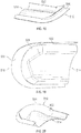
FIGS. 5-8 depict perspective views of a CAC motor cooling flow enhancement cowl in accordance with an embodiment of the disclosure; -
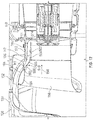
FIG. 9 depicts a partial sectional view of a ram air outlet header and a ram air fan in accordance with an embodiment of the disclosure; -
FIGS. 10-12 depict perspective views of a CAC motor cooling flow enhancement cowl in accordance with an embodiment of the disclosure; -
FIG. 13 depicts a partial sectional view of a ram air outlet header in accordance with an embodiment of the disclosure; -
FIGS. 14-16 depict perspective views of a CAC motor cooling flow enhancement cowl in accordance with an embodiment of the disclosure; -
FIG. 17 depicts a partial sectional view of a ram air outlet header and a ram air fan in accordance with an embodiment of the disclosure; -
FIGS. 18-20 depict perspective views of a CAC motor cooling flow enhancement cowl in accordance with an embodiment of the disclosure; and -
FIG. 21 depicts a process for installing a CAC motor cooling flow enhancement cowl in a ram air outlet header in accordance with an embodiment of the disclosure. - Referring to the drawings, shown in
FIG. 1 is a schematic view of a ramair cooling system 100 for an aircraft environmental control system (ECS). The ramair cooling system 100 includes aram air inlet 102, aram inlet header 104, aheat exchanger assembly 106, a ramair outlet header 108, aram air fan 110, and aram air outlet 112. When opened, a ramair inlet door 114 controlled by a ram airinlet door actuator 116 allowsram air 118 to enter theram inlet header 104, pass through theheat exchanger assembly 106 to the ramair outlet header 108 and exits through theram air outlet 112. A ramair outlet door 120 is controlled by a ram airoutlet door actuator 122 at theram air outlet 112. Theram air fan 110 can be used to increase a flow rate of theram air 118 through the ramair cooling system 100. Alternatively, theram air 118 may be bypassed around theram air fan 110 through a ramair fan housing 138 as depicted inFIG. 2 . Anelectric motor 124 drives theram air fan 110 and may be controlled using aspeed sensor 126. Theelectric motor 124 can receive a ram fan bearingcooling flow 128 drawn from theram inlet header 104. The ramair cooling system 100 may also include acheck valve 130 to control for over-pressure conditions. In an embodiment, theheat exchanger assembly 106 includes aprimary heat exchanger 106A, asecondary heat exchanger 106B, atertiary heat exchanger 106C, and aquaternary heat exchanger 106D. A cooledflow 148 from theprimary heat exchanger 106A may be used to cool various heat loads. A watercollector overflow drain 136 is also routed to the ramair outlet header 108. - Also depicted in
FIG. 1 , a cabin air compressor (CAC) 132 draws in air from the atmosphere through acompressor impeller 133 at aCAC compressor inlet 131 and provides a CACmotor cooling return 134 to the ramair outlet header 108. Thecompressor impeller 133 can be driven by aCAC motor 135. A pressure differential between theCAC compressor inlet 131 and the CACmotor cooling return 134 drives a cooling flow tomotor windings 137 of theCAC motor 135. A higher pressure differential increases a cooling mass flow rate through theCAC motor 135. In embodiments, effectiveness of the cooling can impact the reliability of theCAC motor 135, particularly in high temperature environments. The pressure at theCAC compressor inlet 131 is uncontrolled in the ramair cooling system 100 and is a function of atmospheric pressure. To increase the pressure differential between theCAC compressor inlet 131 and the CACmotor cooling return 134, embodiments reduce the discharge pressure of the CACmotor cooling return 134. -
FIG. 2 is a perspective view of an embodiment of the ramair cooling system 100 ofFIG. 1 . Theheat exchanger assembly 106 is coupled to theram inlet header 104 and the ramair outlet header 108. The ramair outlet header 108 receives heated ram air that passes through theheat exchanger assembly 106. The ramair outlet header 108 also receives a heated bearing cooling supply return from the CACmotor cooling return 134. The ramair outlet header 108 can also receive water at the watercollector overflow drain 136. A ramair fan housing 138 is coupled to the ramair outlet header 108 via aclamp 144 and can receive a combination of heated ram air, heated bearing cooling supply return air, and water. The ramair fan housing 138 contains theram air fan 110,electric motor 124, andspeed sensor 126 ofFIG. 1 . The ramair outlet header 108 also includes a mountingbracket 140 for apack control unit 142. Thepack control unit 142 may include electronics to control electric components of the ramair cooling system 100, such as the ram airinlet door actuator 116, the ram airoutlet door actuator 122, and/or theelectric motor 124 ofFIG. 1 . -
FIG. 3 depicts a cross section of the ramair outlet header 108 ofFIGS. 1 and2 having aheader body 150 with a CAC motor coolingflow enhancement cowl 202 coupled thereto. Further details of the CAC motor coolingflow enhancement cowl 202 are described with respect toFIGS. 4 ,5 ,6 ,7, and 8 . Theheader body 150 includes a CACmotor cooling duct 152 that intersects a ram airfan flow path 154 at a CAC motor coolingduct discharge 156 in abell mouth 158 upstream from a ram airfan inlet interface 160. The CAC motor coolingflow enhancement cowl 202 includes acowl body 204 that extends from the CAC motor coolingduct discharge 156 with a backward facingstep 206 that forms an air dam in the ramair flow path 154 to divert ram system air away from CAC motor coolingduct discharge 156. Acoupling interface 208 is formed at anupstream end 210 of thecowl body 204 to engage with atransition edge 162 of the CAC motor coolingduct discharge 156. Thecoupling interface 208 can be contoured to at least partially wrap around aninterior surface 164 of the CACmotor cooling duct 152 and aninterior surface 166 of thebell mouth 158. - The
cowl body 204 forms a CAC motor coolingduct extension channel 212 with respect to thebell mouth 158. The CAC motor coolingduct extension channel 212 can be sized to partially extend into thebell mouth 158 when thecoupling interface 208 is engaged with thetransition edge 162 of the CAC motor coolingduct discharge 156. In the example ofFIG. 4 , a channel height H2 of the CAC motor coolingduct extension channel 212 is less than a channel height H1 at the CAC motor coolingduct discharge 156. In other embodiments, the channel height H2 of the CAC motor coolingduct extension channel 212 can be greater than or equal to the channel height H1 at the CAC motor coolingduct discharge 156. - In embodiments, the CAC
motor cooling return 134 ofFIG. 1 is routed through the CACmotor cooling duct 152 and the CAC motor coolingduct extension channel 212 to merge with the ram airfan flow path 154 at adownstream end 214 of the CAC motor coolingflow enhancement cowl 202. The backward facingstep 206 creates a lower pressure zone in the ram airfan flow path 154 allowing the CACmotor cooling return 134 to discharge into the ram airfan flow path 154 at a lower static pressure. The reduced static pressure can increase a pressure differential with respect to theCAC motor 135 ofFIG. 1 to drive an increased cooling flow through theCAC motor 135, which reduces the temperature of theCAC motor 135 to increase motor reliability. A number of sizing variations of the CAC motor coolingflow enhancement cowl 202 are contemplated as depicted in the examples ofFIGS. 9-20 . - In the example of
FIGS. 9-12 , CAC motor coolingflow enhancement cowl 302 has acowl body 304 that forms a CAC motor coolingduct extension channel 312 with respect to thebell mouth 158. The CAC motor coolingduct extension channel 312 is sized to extend in thebell mouth 158 beyond the ram airfan inlet interface 160 when couplinginterface 308 is engaged with thetransition edge 162 of the CAC motor coolingduct discharge 156. The backward facingstep 306 can be substantially similar to the backward facingstep 206 ofFIG. 4 . Also, similar to CAC motor coolingduct extension channel 212 ofFIG. 4 , the CAC motor coolingduct extension channel 312 can have a channel height H2 that is less than channel height H1 at the CAC motor coolingduct discharge 156. The extended length of thecowl body 304 between theupstream end 310 and thedownstream end 314 as compared to thecowl body 204 ofFIG. 4 results in CACmotor cooling return 134 exiting the CAC motor coolingduct extension channel 312 in closer proximity to fanblades 111 of theram air fan 110. A greater pressure differential may be achieved by the CAC motor coolingflow enhancement cowl 302 as compared to the CAC motor coolingflow enhancement cowl 202 ofFIG. 2 which may further enhance cooling of theCAC motor 135 ofFIG. 1 . However, the CAC motor coolingflow enhancement cowl 302 may place non-uniform flow distribution loading on thefan blades 111 as compared to the shorter length of the CAC motor coolingflow enhancement cowl 202 which mixes into the ram airfan flow path 154 further upstream. A non-uniform flow distribution can result in non-uniform blade loading on thefan blades 111, which can cause thefan blades 111 to load and unload upon passing the CAC motor coolingflow enhancement cowl 302. This loading and unloading (once per revolution) can possibly cause thefan blades 111 to fatigue, leading to a potential failure if the loading and unloading cycles occur at too large of an amplitude. Using a shorter cowl allows room for the flow non-uniform distribution to mix out before loading differences impact thefan blades 111. - In the example of
FIGS. 13-16 , CAC motor coolingflow enhancement cowl 402 has acowl body 404 that forms a CAC motor coolingduct extension channel 412 with respect to thebell mouth 158. The CAC motor coolingduct extension channel 412 is sized to partially extend into thebell mouth 158 when couplinginterface 408 is engaged with thetransition edge 162 of the CAC motor coolingduct discharge 156. The backward facingstep 406 can be contoured with a different profile than the backward facingstep 206 ofFIG. 4 to make a deeper CAC motor coolingduct extension channel 412 with a channel height H3 that is greater than channel height H2 ofFIG. 4 . Thecowl body 404 between theupstream end 410 and thedownstream end 414 can be similar in length to thecowl body 204 ofFIG. 4 . A greater pressure differential may be achieved by the CAC motor coolingflow enhancement cowl 402 as compared to the CAC motor coolingflow enhancement cowl 202 ofFIG. 2 which may further enhance cooling of theCAC motor 135 ofFIG. 1 due to the increased size of channel height H3. - In the example of
FIGS. 17-20 , CAC motor coolingflow enhancement cowl 502 has acowl body 504 that forms a CAC motor coolingduct extension channel 512 with respect to thebell mouth 158. The CAC motor coolingduct extension channel 512 is sized to extend in thebell mouth 158 beyond the ram airfan inlet interface 160 when couplinginterface 508 is engaged with thetransition edge 162 of the CAC motor coolingduct discharge 156. The backward facingstep 506 can differ from the backward facingstep 206 ofFIG. 4 but can be similar, for instance, to the backward facingstep 406 ofFIG. 13 . Also, similar to CAC motor coolingduct extension channel 412 ofFIG. 13 , the CAC motor coolingduct extension channel 512 can have a channel height H3 that is greater than channel height H2 ofFIG. 4 . The extended length of thecowl body 504 between theupstream end 510 and thedownstream end 514 as compared to thecowl body 204 ofFIG. 4 results in CACmotor cooling return 134 exiting the CAC motor coolingduct extension channel 512 in closer proximity to fanblades 111 of theram air fan 110. A greater pressure differential may be achieved by the CAC motor coolingflow enhancement cowl 502 as compared to the CAC motor coolingflow enhancement cowl 202 ofFIG. 2 which may further enhance cooling of theCAC motor 135 ofFIG. 1 . However, the CAC motor coolingflow enhancement cowl 502 may place a non-uniform loading distribution on thefan blades 111 as compared to the shorter length of the CAC motor coolingflow enhancement cowl 202 which mixes into the ram airfan flow path 154 further upstream. Thus, as can be seen, adjusting various sizing parameters of a CAC motor cooling flow enhancement cowl can balance cooling effects on theCAC motor 135 and loading onfan blades 111. - A
method 600 of installing a CAC motor coolingflow enhancement cowl air outlet header 108 is described in reference toFIGS. 1-21 . Atblock 610, acowl body step flow enhancement cowl air flow path 154 of the ramair outlet header 108 to divert ram system air away from a CAC motor coolingduct discharge 156 in abell mouth 158 upstream from a ram airfan inlet interface 160 of the ramair outlet header 108. Atblock 620, acoupling interface flow enhancement cowl transition edge 162 of the CAC motor coolingduct discharge 156. Thecoupling interface interior surface 164 of a CACmotor cooling duct 152 of the ramair outlet header 108 and aninterior surface 166 of thebell mouth 158. Thecowl body duct extension channel bell mouth 158. The CAC motor coolingduct extension channel bell mouth 158 or beyond the ram airfan inlet interface 160. A channel height H2, H3 of the CAC motor coolingduct extension channel duct discharge 156. - The term "about" is intended to include the degree of error associated with measurement of the particular quantity based upon the equipment available at the time of filing the application. For example, "about" can include a range of ± 8% or 5%, or 2% of a given value.
- The terminology used herein is for the purpose of describing particular embodiments only and is not intended to be limiting of the present disclosure. As used herein, the singular forms "a", "an" and "the" are intended to include the plural forms as well, unless the context clearly indicates otherwise. It will be further understood that the terms "comprises" and/or "comprising," when used in this specification, specify the presence of stated features, integers, steps, operations, elements, and/or components, but do not preclude the presence or addition of one or more other features, integers, steps, operations, element components, and/or groups thereof.
- While the present disclosure has been described with reference to an exemplary embodiment or embodiments, it will be understood by those skilled in the art that various changes may be made and equivalents may be substituted for elements thereof without departing from the scope of the present invention as defined by the claims. In addition, many modifications may be made to adapt a particular situation or material to the teachings of the present disclosure without departing from the scope of the invention. Therefore, it is intended that the present invention not be limited to the particular embodiment disclosed as the best mode contemplated for carrying out this present invention, but that the present invention will include all embodiments falling within the scope of the claims.
Claims (14)
- A cabin air compressor, CAC, motor cooling flow enhancement cowl, comprising:a cowl body (204) contoured to extend from a CAC motor cooling duct discharge (156) of a ram air outlet header (108), the cowl body comprising a backward facing step (206) to form an air dam in a ram air flow path to divert ram system air away from the CAC motor cooling duct discharge; anda coupling interface (308) formed at an upstream end of the cowl body to engage with a transition edge (162) of the CAC motor cooling duct discharge.
- The CAC motor cooling flow enhancement cowl of claim 1, wherein the cowl body forms a CAC motor cooling duct extension channel (212) with respect to a bell mouth (158) of the ram air outlet header upstream from a ram air fan inlet interface of the ram air outlet header.
- The CAC motor cooling flow enhancement cowl of claim 2, wherein the CAC motor cooling duct extension channel (212) is sized to partially extend into the bell mouth (158) when the coupling interface (308) is engaged with the transition edge (162) of the CAC motor cooling duct discharge.
- The CAC motor cooling flow enhancement cowl of claim 2, wherein the CAC motor cooling duct extension channel (212) is sized to extend in the bell mouth (158) beyond the ram air fan inlet interface when the coupling interface (308) is engaged with the transition edge of the CAC motor cooling duct discharge.
- The CAC motor cooling flow enhancement cowl of claim 2, 3 or 4, wherein a channel height of the CAC motor cooling duct extension channel is less than a channel height at the CAC motor cooling duct discharge.
- The CAC motor cooling flow enhancement cowl of claim 2, 3 or 4, wherein a channel height of the CAC motor cooling duct extension channel is greater than a channel height at the CAC motor cooling duct discharge.
- The CAC motor cooling flow enhancement cowl of any preceding claim, wherein the coupling interface is contoured to at least partially wrap around an interior surface of a CAC motor cooling duct of the ram air outlet header and an interior surface of the bell mouth.
- A ram air outlet header comprising:a header body comprising a CAC motor cooling duct that intersects a ram air fan flow path at a CAC motor cooling duct discharge in a bell mouth upstream from a ram air fan inlet interface; andthe CAC motor cooling flow enhancement cowl of any preceding claim.
- A method for installing a cabin air compressor (CAC) motor cooling flow enhancement cowl in a ram air outlet header, the method comprising:positioning a cowl body comprising a backward facing step of the CAC motor cooling flow enhancement cowl to form an air dam in a ram air flow path of the ram air outlet header to divert ram system air away from a CAC motor cooling duct discharge in a bell mouth upstream from a ram air fan inlet interface of the ram air outlet header; andfastening a coupling interface of the CAC motor cooling flow enhancement cowl to a transition edge of the CAC motor cooling duct discharge.
- The method of claim 9, wherein the cowl body forms a CAC motor cooling duct extension channel with respect to the bell mouth.
- The method of claim 10, wherein the CAC motor cooling duct extension channel extends in the bell mouth beyond the ram air fan inlet interface.
- The method of claim 10, wherein a channel height of the CAC motor cooling duct extension channel is less than a channel height at the CAC motor cooling duct discharge.
- The method of claim 10, wherein a channel height of the CAC motor cooling duct extension channel is greater than a channel height at the CAC motor cooling duct discharge.
- The method of claim 9, wherein the coupling interface is contoured to at least partially wrap around an interior surface of a CAC motor cooling duct of the ram air outlet header and an interior surface of the bell mouth.
Applications Claiming Priority (1)
| Application Number | Priority Date | Filing Date | Title |
|---|---|---|---|
| US15/646,589 US10807722B2 (en) | 2017-07-11 | 2017-07-11 | Cabin air compressor motor cooling flow enhancement cowl |
Publications (2)
| Publication Number | Publication Date |
|---|---|
| EP3428069A1 true EP3428069A1 (en) | 2019-01-16 |
| EP3428069B1 EP3428069B1 (en) | 2021-01-06 |
Family
ID=62916538
Family Applications (1)
| Application Number | Title | Priority Date | Filing Date |
|---|---|---|---|
| EP18182893.0A Active EP3428069B1 (en) | 2017-07-11 | 2018-07-11 | Cabin air compressor motor cooling flow enhancement cowl |
Country Status (2)
| Country | Link |
|---|---|
| US (1) | US10807722B2 (en) |
| EP (1) | EP3428069B1 (en) |
Cited By (2)
| Publication number | Priority date | Publication date | Assignee | Title |
|---|---|---|---|---|
| EP4349713A1 (en) * | 2022-10-07 | 2024-04-10 | Hamilton Sundstrand Corporation | High-power air-coooled compressor motor and low-power cooling booster fan motor powered by single inverter |
| EP4382428A1 (en) * | 2022-12-05 | 2024-06-12 | Hamilton Sundstrand Corporation | Centerbody insertion for improved cac motor cooling |
Families Citing this family (4)
| Publication number | Priority date | Publication date | Assignee | Title |
|---|---|---|---|---|
| US11661954B2 (en) | 2021-09-08 | 2023-05-30 | Hamilton Sundstrand Corporation | Cabin air compressor with bleed scoop and removable bleed duct filter |
| US12129036B2 (en) * | 2022-01-19 | 2024-10-29 | Hamilton Sundstrand Corporation | Component cooling and cooling air flow generation from remote heat exchanger |
| CN114802776B (en) * | 2022-02-24 | 2025-01-03 | 南京航空航天大学 | Embedded air inlet based on swept step to displace the forebody boundary layer |
| US12395044B2 (en) | 2023-02-14 | 2025-08-19 | Hamilton Sundstrand Corporation | CAC motor auxiliary water cooling system |
Citations (5)
| Publication number | Priority date | Publication date | Assignee | Title |
|---|---|---|---|---|
| US20010025506A1 (en) * | 2000-03-29 | 2001-10-04 | Buchholz Uwe Albert | Cooling air arrangement for a heat exchanger of an aircraft air conditioning unit |
| WO2003037715A1 (en) * | 2001-10-29 | 2003-05-08 | Pratt & Whitney Canada Corp. | Passive cooling system for auxiliary power unit installation |
| US20100258655A1 (en) * | 2009-04-09 | 2010-10-14 | Alexander Solntsev | Ram air outlet duct |
| US20140048229A1 (en) * | 2012-08-15 | 2014-02-20 | Hamilton Sundstrand Corporation | Ram outlet header |
| EP2808257A1 (en) * | 2013-05-28 | 2014-12-03 | Hamilton Sundstrand Corporation | Motor cooling blower and containment structure |
Family Cites Families (6)
| Publication number | Priority date | Publication date | Assignee | Title |
|---|---|---|---|---|
| US7188488B2 (en) | 2003-03-12 | 2007-03-13 | Hamilton Sundstrand | Pack and a half condensing cycle pack with combined heat exchangers |
| US9764846B2 (en) * | 2013-04-03 | 2017-09-19 | Hamilton Sundstrand Corporation | Contamination free reverse flow fitting |
| US9685835B2 (en) | 2013-10-11 | 2017-06-20 | Hamilton Sundstrand Corporation | Motor housing having conical shaped ends with various dimensional ratios and slopes for a stator in an avionics cabin air compressor |
| FR3015573B1 (en) * | 2013-12-19 | 2015-12-11 | Snecma | AIRCRAFT TURBOMACHINE COMPRISING A HEAT EXCHANGER OF THE PRE-COOLING TYPE |
| US10526091B2 (en) * | 2014-12-03 | 2020-01-07 | The Boeing Company | Mobile platform thermal management systems and methods |
| US10625868B2 (en) * | 2016-07-12 | 2020-04-21 | Sikorsky Aircraft Corporation | Bleed air heat ejectors |
-
2017
- 2017-07-11 US US15/646,589 patent/US10807722B2/en active Active
-
2018
- 2018-07-11 EP EP18182893.0A patent/EP3428069B1/en active Active
Patent Citations (5)
| Publication number | Priority date | Publication date | Assignee | Title |
|---|---|---|---|---|
| US20010025506A1 (en) * | 2000-03-29 | 2001-10-04 | Buchholz Uwe Albert | Cooling air arrangement for a heat exchanger of an aircraft air conditioning unit |
| WO2003037715A1 (en) * | 2001-10-29 | 2003-05-08 | Pratt & Whitney Canada Corp. | Passive cooling system for auxiliary power unit installation |
| US20100258655A1 (en) * | 2009-04-09 | 2010-10-14 | Alexander Solntsev | Ram air outlet duct |
| US20140048229A1 (en) * | 2012-08-15 | 2014-02-20 | Hamilton Sundstrand Corporation | Ram outlet header |
| EP2808257A1 (en) * | 2013-05-28 | 2014-12-03 | Hamilton Sundstrand Corporation | Motor cooling blower and containment structure |
Cited By (4)
| Publication number | Priority date | Publication date | Assignee | Title |
|---|---|---|---|---|
| EP4349713A1 (en) * | 2022-10-07 | 2024-04-10 | Hamilton Sundstrand Corporation | High-power air-coooled compressor motor and low-power cooling booster fan motor powered by single inverter |
| US12480527B2 (en) | 2022-10-07 | 2025-11-25 | Hamilton Sundstrand Corporation | High-power air-coooled compressor motor and low-power cooling booster fan motor powered by single inverter |
| EP4382428A1 (en) * | 2022-12-05 | 2024-06-12 | Hamilton Sundstrand Corporation | Centerbody insertion for improved cac motor cooling |
| US12135036B2 (en) | 2022-12-05 | 2024-11-05 | Hamilton Sundstrand Corporation | Centerbody insertion for improved CAC motor cooling |
Also Published As
| Publication number | Publication date |
|---|---|
| US10807722B2 (en) | 2020-10-20 |
| EP3428069B1 (en) | 2021-01-06 |
| US20190016465A1 (en) | 2019-01-17 |
Similar Documents
| Publication | Publication Date | Title |
|---|---|---|
| EP3428069B1 (en) | Cabin air compressor motor cooling flow enhancement cowl | |
| US7334422B2 (en) | Cabin air conditioning system with liquid cooling for power electronics | |
| EP2407380B1 (en) | Cabin air compressor motor cooling | |
| EP2711296B1 (en) | Cooling arrangement for a motor assembly and method of cooling a motor assembly | |
| EP3539876B1 (en) | Bearing housing for ram air fan | |
| EP2808257B1 (en) | Motor cooling blower and containment structure | |
| US9546669B2 (en) | Compressor housing for an air cycle machine | |
| US20170175748A1 (en) | Thermal enhancement of cabin air compressor motor cooling | |
| EP4019785B1 (en) | Cabin air compressor with liquid cooled jacket | |
| EP4001663B1 (en) | Improved bearing cooling schemes for aircraft fans | |
| US9057386B2 (en) | Ram air fan inner housing | |
| WO2017221460A1 (en) | Air conditioning apparatus | |
| EP3173336B1 (en) | Supply tube for sensor | |
| EP4261417A1 (en) | Compressor with motor cooling impeller | |
| US11434923B2 (en) | Fan rotor for ram air fan | |
| US6754075B2 (en) | Motor-fan unit particularly for a heating and/or air conditioning apparatus for a motor vehicle | |
| EP3540241A1 (en) | Labyrinth seal for fan assembly | |
| US9347455B2 (en) | Ejector assembly | |
| US10788046B2 (en) | Fan and compressor housing for an air cycle machine | |
| EP4382429A2 (en) | Recirculation air motor driven acm | |
| EP3539877A1 (en) | Housing for a ram air fan motor | |
| US9365296B2 (en) | Transfer tube for a ram air fan (RAF) assembly | |
| KR20060110601A (en) | Air inlet structure for blower motor cooling |
Legal Events
| Date | Code | Title | Description |
|---|---|---|---|
| PUAI | Public reference made under article 153(3) epc to a published international application that has entered the european phase |
Free format text: ORIGINAL CODE: 0009012 |
|
| STAA | Information on the status of an ep patent application or granted ep patent |
Free format text: STATUS: THE APPLICATION HAS BEEN PUBLISHED |
|
| AK | Designated contracting states |
Kind code of ref document: A1 Designated state(s): AL AT BE BG CH CY CZ DE DK EE ES FI FR GB GR HR HU IE IS IT LI LT LU LV MC MK MT NL NO PL PT RO RS SE SI SK SM TR |
|
| AX | Request for extension of the european patent |
Extension state: BA ME |
|
| STAA | Information on the status of an ep patent application or granted ep patent |
Free format text: STATUS: REQUEST FOR EXAMINATION WAS MADE |
|
| 17P | Request for examination filed |
Effective date: 20190716 |
|
| RBV | Designated contracting states (corrected) |
Designated state(s): AL AT BE BG CH CY CZ DE DK EE ES FI FR GB GR HR HU IE IS IT LI LT LU LV MC MK MT NL NO PL PT RO RS SE SI SK SM TR |
|
| GRAP | Despatch of communication of intention to grant a patent |
Free format text: ORIGINAL CODE: EPIDOSNIGR1 |
|
| STAA | Information on the status of an ep patent application or granted ep patent |
Free format text: STATUS: GRANT OF PATENT IS INTENDED |
|
| INTG | Intention to grant announced |
Effective date: 20200722 |
|
| GRAS | Grant fee paid |
Free format text: ORIGINAL CODE: EPIDOSNIGR3 |
|
| GRAA | (expected) grant |
Free format text: ORIGINAL CODE: 0009210 |
|
| STAA | Information on the status of an ep patent application or granted ep patent |
Free format text: STATUS: THE PATENT HAS BEEN GRANTED |
|
| AK | Designated contracting states |
Kind code of ref document: B1 Designated state(s): AL AT BE BG CH CY CZ DE DK EE ES FI FR GB GR HR HU IE IS IT LI LT LU LV MC MK MT NL NO PL PT RO RS SE SI SK SM TR |
|
| REG | Reference to a national code |
Ref country code: GB Ref legal event code: FG4D |
|
| REG | Reference to a national code |
Ref country code: AT Ref legal event code: REF Ref document number: 1352081 Country of ref document: AT Kind code of ref document: T Effective date: 20210115 Ref country code: CH Ref legal event code: EP |
|
| REG | Reference to a national code |
Ref country code: DE Ref legal event code: R096 Ref document number: 602018011504 Country of ref document: DE |
|
| REG | Reference to a national code |
Ref country code: IE Ref legal event code: FG4D |
|
| REG | Reference to a national code |
Ref country code: NL Ref legal event code: MP Effective date: 20210106 |
|
| REG | Reference to a national code |
Ref country code: AT Ref legal event code: MK05 Ref document number: 1352081 Country of ref document: AT Kind code of ref document: T Effective date: 20210106 |
|
| REG | Reference to a national code |
Ref country code: LT Ref legal event code: MG9D |
|
| PG25 | Lapsed in a contracting state [announced via postgrant information from national office to epo] |
Ref country code: BG Free format text: LAPSE BECAUSE OF FAILURE TO SUBMIT A TRANSLATION OF THE DESCRIPTION OR TO PAY THE FEE WITHIN THE PRESCRIBED TIME-LIMIT Effective date: 20210406 Ref country code: HR Free format text: LAPSE BECAUSE OF FAILURE TO SUBMIT A TRANSLATION OF THE DESCRIPTION OR TO PAY THE FEE WITHIN THE PRESCRIBED TIME-LIMIT Effective date: 20210106 Ref country code: FI Free format text: LAPSE BECAUSE OF FAILURE TO SUBMIT A TRANSLATION OF THE DESCRIPTION OR TO PAY THE FEE WITHIN THE PRESCRIBED TIME-LIMIT Effective date: 20210106 Ref country code: GR Free format text: LAPSE BECAUSE OF FAILURE TO SUBMIT A TRANSLATION OF THE DESCRIPTION OR TO PAY THE FEE WITHIN THE PRESCRIBED TIME-LIMIT Effective date: 20210407 Ref country code: LT Free format text: LAPSE BECAUSE OF FAILURE TO SUBMIT A TRANSLATION OF THE DESCRIPTION OR TO PAY THE FEE WITHIN THE PRESCRIBED TIME-LIMIT Effective date: 20210106 Ref country code: PT Free format text: LAPSE BECAUSE OF FAILURE TO SUBMIT A TRANSLATION OF THE DESCRIPTION OR TO PAY THE FEE WITHIN THE PRESCRIBED TIME-LIMIT Effective date: 20210506 Ref country code: NO Free format text: LAPSE BECAUSE OF FAILURE TO SUBMIT A TRANSLATION OF THE DESCRIPTION OR TO PAY THE FEE WITHIN THE PRESCRIBED TIME-LIMIT Effective date: 20210406 |
|
| PG25 | Lapsed in a contracting state [announced via postgrant information from national office to epo] |
Ref country code: AT Free format text: LAPSE BECAUSE OF FAILURE TO SUBMIT A TRANSLATION OF THE DESCRIPTION OR TO PAY THE FEE WITHIN THE PRESCRIBED TIME-LIMIT Effective date: 20210106 Ref country code: LV Free format text: LAPSE BECAUSE OF FAILURE TO SUBMIT A TRANSLATION OF THE DESCRIPTION OR TO PAY THE FEE WITHIN THE PRESCRIBED TIME-LIMIT Effective date: 20210106 Ref country code: PL Free format text: LAPSE BECAUSE OF FAILURE TO SUBMIT A TRANSLATION OF THE DESCRIPTION OR TO PAY THE FEE WITHIN THE PRESCRIBED TIME-LIMIT Effective date: 20210106 Ref country code: RS Free format text: LAPSE BECAUSE OF FAILURE TO SUBMIT A TRANSLATION OF THE DESCRIPTION OR TO PAY THE FEE WITHIN THE PRESCRIBED TIME-LIMIT Effective date: 20210106 Ref country code: SE Free format text: LAPSE BECAUSE OF FAILURE TO SUBMIT A TRANSLATION OF THE DESCRIPTION OR TO PAY THE FEE WITHIN THE PRESCRIBED TIME-LIMIT Effective date: 20210106 |
|
| PG25 | Lapsed in a contracting state [announced via postgrant information from national office to epo] |
Ref country code: IS Free format text: LAPSE BECAUSE OF FAILURE TO SUBMIT A TRANSLATION OF THE DESCRIPTION OR TO PAY THE FEE WITHIN THE PRESCRIBED TIME-LIMIT Effective date: 20210506 |
|
| REG | Reference to a national code |
Ref country code: DE Ref legal event code: R097 Ref document number: 602018011504 Country of ref document: DE |
|
| PG25 | Lapsed in a contracting state [announced via postgrant information from national office to epo] |
Ref country code: CZ Free format text: LAPSE BECAUSE OF FAILURE TO SUBMIT A TRANSLATION OF THE DESCRIPTION OR TO PAY THE FEE WITHIN THE PRESCRIBED TIME-LIMIT Effective date: 20210106 Ref country code: EE Free format text: LAPSE BECAUSE OF FAILURE TO SUBMIT A TRANSLATION OF THE DESCRIPTION OR TO PAY THE FEE WITHIN THE PRESCRIBED TIME-LIMIT Effective date: 20210106 Ref country code: SM Free format text: LAPSE BECAUSE OF FAILURE TO SUBMIT A TRANSLATION OF THE DESCRIPTION OR TO PAY THE FEE WITHIN THE PRESCRIBED TIME-LIMIT Effective date: 20210106 |
|
| PLBE | No opposition filed within time limit |
Free format text: ORIGINAL CODE: 0009261 |
|
| STAA | Information on the status of an ep patent application or granted ep patent |
Free format text: STATUS: NO OPPOSITION FILED WITHIN TIME LIMIT |
|
| PG25 | Lapsed in a contracting state [announced via postgrant information from national office to epo] |
Ref country code: DK Free format text: LAPSE BECAUSE OF FAILURE TO SUBMIT A TRANSLATION OF THE DESCRIPTION OR TO PAY THE FEE WITHIN THE PRESCRIBED TIME-LIMIT Effective date: 20210106 Ref country code: SK Free format text: LAPSE BECAUSE OF FAILURE TO SUBMIT A TRANSLATION OF THE DESCRIPTION OR TO PAY THE FEE WITHIN THE PRESCRIBED TIME-LIMIT Effective date: 20210106 Ref country code: RO Free format text: LAPSE BECAUSE OF FAILURE TO SUBMIT A TRANSLATION OF THE DESCRIPTION OR TO PAY THE FEE WITHIN THE PRESCRIBED TIME-LIMIT Effective date: 20210106 |
|
| 26N | No opposition filed |
Effective date: 20211007 |
|
| PG25 | Lapsed in a contracting state [announced via postgrant information from national office to epo] |
Ref country code: AL Free format text: LAPSE BECAUSE OF FAILURE TO SUBMIT A TRANSLATION OF THE DESCRIPTION OR TO PAY THE FEE WITHIN THE PRESCRIBED TIME-LIMIT Effective date: 20210106 Ref country code: ES Free format text: LAPSE BECAUSE OF FAILURE TO SUBMIT A TRANSLATION OF THE DESCRIPTION OR TO PAY THE FEE WITHIN THE PRESCRIBED TIME-LIMIT Effective date: 20210106 |
|
| REG | Reference to a national code |
Ref country code: DE Ref legal event code: R119 Ref document number: 602018011504 Country of ref document: DE |
|
| PG25 | Lapsed in a contracting state [announced via postgrant information from national office to epo] |
Ref country code: SI Free format text: LAPSE BECAUSE OF FAILURE TO SUBMIT A TRANSLATION OF THE DESCRIPTION OR TO PAY THE FEE WITHIN THE PRESCRIBED TIME-LIMIT Effective date: 20210106 |
|
| REG | Reference to a national code |
Ref country code: CH Ref legal event code: PL |
|
| PG25 | Lapsed in a contracting state [announced via postgrant information from national office to epo] |
Ref country code: MC Free format text: LAPSE BECAUSE OF FAILURE TO SUBMIT A TRANSLATION OF THE DESCRIPTION OR TO PAY THE FEE WITHIN THE PRESCRIBED TIME-LIMIT Effective date: 20210106 |
|
| REG | Reference to a national code |
Ref country code: BE Ref legal event code: MM Effective date: 20210731 |
|
| PG25 | Lapsed in a contracting state [announced via postgrant information from national office to epo] |
Ref country code: LI Free format text: LAPSE BECAUSE OF NON-PAYMENT OF DUE FEES Effective date: 20210731 Ref country code: IT Free format text: LAPSE BECAUSE OF FAILURE TO SUBMIT A TRANSLATION OF THE DESCRIPTION OR TO PAY THE FEE WITHIN THE PRESCRIBED TIME-LIMIT Effective date: 20210106 Ref country code: DE Free format text: LAPSE BECAUSE OF NON-PAYMENT OF DUE FEES Effective date: 20220201 Ref country code: CH Free format text: LAPSE BECAUSE OF NON-PAYMENT OF DUE FEES Effective date: 20210731 |
|
| PG25 | Lapsed in a contracting state [announced via postgrant information from national office to epo] |
Ref country code: IS Free format text: LAPSE BECAUSE OF FAILURE TO SUBMIT A TRANSLATION OF THE DESCRIPTION OR TO PAY THE FEE WITHIN THE PRESCRIBED TIME-LIMIT Effective date: 20210506 Ref country code: LU Free format text: LAPSE BECAUSE OF NON-PAYMENT OF DUE FEES Effective date: 20210711 |
|
| PG25 | Lapsed in a contracting state [announced via postgrant information from national office to epo] |
Ref country code: IE Free format text: LAPSE BECAUSE OF NON-PAYMENT OF DUE FEES Effective date: 20210711 Ref country code: BE Free format text: LAPSE BECAUSE OF NON-PAYMENT OF DUE FEES Effective date: 20210731 |
|
| P01 | Opt-out of the competence of the unified patent court (upc) registered |
Effective date: 20230522 |
|
| PG25 | Lapsed in a contracting state [announced via postgrant information from national office to epo] |
Ref country code: NL Free format text: LAPSE BECAUSE OF NON-PAYMENT OF DUE FEES Effective date: 20210206 Ref country code: CY Free format text: LAPSE BECAUSE OF FAILURE TO SUBMIT A TRANSLATION OF THE DESCRIPTION OR TO PAY THE FEE WITHIN THE PRESCRIBED TIME-LIMIT Effective date: 20210106 |
|
| PG25 | Lapsed in a contracting state [announced via postgrant information from national office to epo] |
Ref country code: HU Free format text: LAPSE BECAUSE OF FAILURE TO SUBMIT A TRANSLATION OF THE DESCRIPTION OR TO PAY THE FEE WITHIN THE PRESCRIBED TIME-LIMIT; INVALID AB INITIO Effective date: 20180711 |
|
| PG25 | Lapsed in a contracting state [announced via postgrant information from national office to epo] |
Ref country code: MK Free format text: LAPSE BECAUSE OF FAILURE TO SUBMIT A TRANSLATION OF THE DESCRIPTION OR TO PAY THE FEE WITHIN THE PRESCRIBED TIME-LIMIT Effective date: 20210106 |
|
| PG25 | Lapsed in a contracting state [announced via postgrant information from national office to epo] |
Ref country code: MT Free format text: LAPSE BECAUSE OF FAILURE TO SUBMIT A TRANSLATION OF THE DESCRIPTION OR TO PAY THE FEE WITHIN THE PRESCRIBED TIME-LIMIT Effective date: 20210106 |
|
| PGFP | Annual fee paid to national office [announced via postgrant information from national office to epo] |
Ref country code: GB Payment date: 20250619 Year of fee payment: 8 |
|
| PGFP | Annual fee paid to national office [announced via postgrant information from national office to epo] |
Ref country code: FR Payment date: 20250619 Year of fee payment: 8 |
|
| PG25 | Lapsed in a contracting state [announced via postgrant information from national office to epo] |
Ref country code: TR Free format text: LAPSE BECAUSE OF FAILURE TO SUBMIT A TRANSLATION OF THE DESCRIPTION OR TO PAY THE FEE WITHIN THE PRESCRIBED TIME-LIMIT Effective date: 20210106 |